raytheon - united states naval academy
TRANSCRIPT
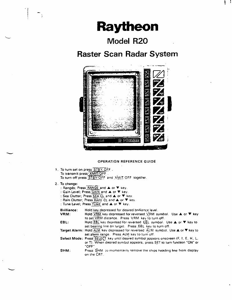
Raytheon Model R20
Raster Scan Radar System
OPERATION REFERENCE GUIDE
1 . To turn set on press CS'fEiY.D~F . To transmit press i XMIT/OFF .. To turn off press l)TBY.1Q£.( and f~_[T OFF together.
2. To change: : Ranges; Press~·GE-and A. or 'Y key. : Gain Level; Press GAIN and A. or 'Y key. : Sea Clutter; Pres; SEA-CL and A or 'Y key. : Rain Clutter; PressRA1"N-CL and A. or 'Y key. : Tune Level; Press-fUNi[ and A. or 'Y key.
Brilliance: VRM:
EBL:
Hold key depressed for desired brilliance level. Hold VRM- key depressed for reversed _\[RM symbol. Use A or 'Y key to set VRM distance. Press VRM key to turn off. Hold EBL key depressd for rev.ersed EAL symbol. Use A. or 'Y key to set bearing line on target. Press EB_L key to turn off.
Target Alarm: Hold.ALM key depressed for reversed ~LM symbol. Use A. or 'Y key to set alarm range. Press_ALM._ key to turn off.
Select Mode: Press'SELECT key until desired symbol appears onscreen (F. I, E. H. L. or T). Whe;desired symbol appears. p'ress S_ET to turn function HONH or "OFFH.
SHM: Press 5-HM to momentarily remove the ships heading line from display on the CRT.

Raytheon Model R20
Raster Scan Radar System ____ ,,,__ .. _ .. , ... - " ...
~------------- ·-----· .. ·--
CONTROLS 1 . POWER ·················Controls power to the radar (OFF. STBY or XMIT). 2 . RANGE········· .. ··· .. ·· Decreases' increases operating range scale of radar display. 3 . TUNE············ .... · ···Adjusts receiver for maximum target reception. 4 . GAIN ·····················Controls setting of receiver gain. 5 . SEA CLUTTER········ Minimizes sea clutter by reducing nearby gain. 6 . RAIN CLUTTER······Reduces effects of rain or snow on display. 7 . VRM······················Controls VRM for accurate distance measurements. 8. EBL··················· ···Controls EBL for accurate bearing measurements. 9 . ALM ······················Enables, and sets target guard zone 10. BRIL···················· .. Adjusts intensity of the screen. 11. SHM······················Turns SHM OFF while depressed I momentary). 12. SELECT ·················Selects 6 functions below.
F ......... Turns fixed markers "ON'" or "OFF". I ·········Eliminates interference from other ship radars. E ·········Expands target echoes for better v1ewab1hty. H ·········"Freezes'" the picture while the "SET"' key 1s held depressed. L ······ .. ·Displays LAT LONG data from Loran T ·········Displays TD data from Loran.
SET ....................... Turns the above functions ON or Oi=F '-----·------- -
I
,......,\;\.JVLV ;\,I
( UV• LI" ''!'LO (.I
•
.~
• ~·1.
(
SECTION 3
OPERATION
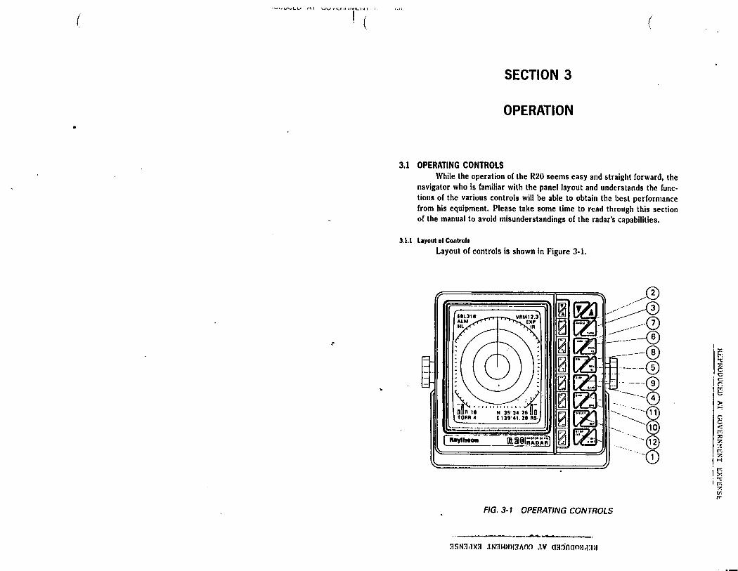
3.1 OPERATING CONTROLS While the operation of the R20 seems easy and straight forward, the
navigator who is familiar with the panel layout and understands the func· lions of the various controls will be able to obtain the best performance from his equipment. Please take some time to read through this section of the manual to avoid misunderstandings of the radar's capabilities.
3.1.l Layout of Control•
Layout of controls is shown in Figure 3-1.
\:' ------ /;;·· ~:1.
n ............. rr n A 1e N 3s· 34. 2s un TORR 4 E 139'41. 28 RS·
-----· --~:~~-=--=·-··-
0 ra ~"- ........ ..-~ l2l k••. . -· _.--0
·- ·--- f6' !;;! f?l- ------\J ~ ~. ----® ~ rzr . ~----® r.2 Fjtl _ . - . fo\ rd ~ -- -----~
0 lZl: -. ~--0 ra rlJ ~---~~ I") ~ --. ·@ ~ ~ ·-.:.·--@
l'l::::=====dl::=.::!J --. -0
FIG. 3-1 OPERATING CONTROLS
------ ....... ~·--------::ISNIJ.JXll .T.N'll~Nmll\0:1 .J.V m1:>nom1d:rn
II:;-:
ti: "C
~ .c 1g I (;
~ ~ < rr. ::e 7. ... r;,
I 7. j i-!
i P. I;;;
7. v. rr
--

3.1.2 The controls
<D POWER I ST-BY/OFFI, IX-MIT/OFF I KEYS
In the "OFF" state no power applied to the Radar system. Upon pressing the I ST-BY/OFF I key, power is supplied to the scanner and Display Unit, and the sign "R20" is displayed in the middle of screen during the warm-up condition. Approximately 90 seconds after the initial switching to ST-BY, the sign "R20" will disappear from the screen and the sign "READY"· will be displayed on the screen. The radar is now ready and available for operation. Pressing the IX-MIT/OFF I key, (with the sign "READY" displayed) puts the radar to transmit and echoes from targets will be received, amplified, and displayed on your screen. By pressing the I ST-BY/OFF I key, the radar returns to "Standby" condition with the transmitter "OFF" and "STANDBY" appears in the CRT center. By pressing the I ST-BY /OFF! and IX-MIT/OFF I keys simultaneously, the radar will turn "OFF" and all Alpha-Numeric information will extinguish.
@ RANGE C....,.I R....,.AN~G-=·1~~ I 'V, !J.) By holding the I RANGE I key depressed until the buzzer sounds, the "R" character or RANGE indication located on the lert bottom corner or display will be displayed as reversed character. [[) By pressing the 'V or 6 key, the desired RANGE scale can be selected. At the initial turn-on, the radar will be on the 2 nm range. Upon pressing the key 6, the range increments by one step, conversly the range decrements by the key 'V. If the 'V or 6 key is held depressed, the range will continue stepping successively in the desired direction. The selected range automatically determines the proper number and distance betwteen the range rings.
TABLE 3-1 RELATION OF RANGE, RINGS AND PULSE LENGTH
Range Rings Distance Between
0.25 nm 2 0.125 nm 0.5 nm 2 0.25 nm l nm 4 0.25 nm 2 nm 4 0.5 nm 4 nm 4 l nm 8 nm 4 2 nm
16 nm 4 4 nm
3 - 2
(
.~
(
@ TUNE CITUNE I 'V, /J.) By holding the fTITiiIBl key depressed until the buzzer sounds, the "T" character of TUNE indication located on the lert bottom corner of display will be displayed as reversed character. II] By pressing the 'V or 6 key, the TUNE control will maximize the target echoes. If land targets are not within the radar's range, adjust the control for maximize sea clutter return. An on-screen bar indicates the "TUNE" position in its range.
© GAIN c[fillli] 'V, !J.) By holding the I GAIN I key depressed until the buzzer sounds, the "G"; character or GAIN indication will be displayed as reversed character. [ill By pressing the 'V or 6 key, the GAIN control is varied and thus controls the strength or echo returns on the radar screen. An onscreen bar indicates the Gain level selected for display.
® SEA CLUTTER Cl SEA CL I 'V, !J.) By holding the I SEA CLUTTER I key depressed until the buzzer sounds, the "S" character or SEA CLUTTER will be displayed as reversed character. [fil By pressing the 'V or 6 key, the SEA CLUTTER level varies the near-by gain on short ranges. The echo returns from sea surface. Clutter can be reduced when the STC Gain is increased. There is an on screen bar indication of the STC level in use.
@ RAIN CLUTTER cl RAIN CL I 'V, !J.) By holding the I RAIN CL I key depressed until the buzzer sounds, the "R" character or RAIN CLUTTER will be displayed as reversed character.[[] By pressing the 'V, or 6 key, the RAIN CLUTTER control can break up the returns from rain or snow thus allowing weaker targets to become visible. As you pu'sh the '6. key, the echoes will become narrow and the returns from rain or snow will be reduced. An onscreen bar indicates the selected rain clutter level.
0 VRM <CTEMJ 'V, /J.) By holding the VRM key depressed until the buzzer sounds, the "VRM" characters will be displayed as reversed character. I VRM I By pressing the 'V or 6 key, the VRM position is changed. U the VRM key is depressed for a short time, the VRM can be turned "OFF". The VRM distance is displayed on the CRT arter the VRM characters in "nautical miles."
3SN3dX3 lN3HNH3AOO lV 033000Ud3H z
i f.1 • "C
Is •o jg '1'1
0
~
8 <: l"1 :;o ?. ::!: l"1 ?. H
I~ I~
(II rr.
'"-' •• ....., V\,... \.J ' ' t '·JI'-" " ~.I " "'"'•<...I " I
(
® EBL cm:IDJ \/. 6 >
By holding the EBL key depressed until the buzzer sounds, the "EBL" characters will be displayed as reversed character. I EBL I Dy pressing the \/ or 6 key, the EBL bearing line is rotated. U the EBL key i.s depressed again, the EBL display turns "OFF". The EBL position in degrees is displayed on the CRT left top side after the "EBL" characters.
® SEAGUARD ALARM (~\/I 6) By holding the I ALM I key depressed until the buzzer sounds, the reversed "ALM" ·Characters are displayed on the CRT. I ALM] By pressing the \/ or 6 key, the ALARM range can be varied. If the ALM key depressed again, the ALARM function turns OFF. While the alarm function is Off, "ALM" range characters are not displayed.
@ BRILLIANCE <rIDillJ \/I 6) By depressing the BRIL key, the brightness of the screen and the panel illumination can be varied in intensity. When holding this key continuously until a buzzer sounds, the brilliance will be at its minfmum level. The next brilliance step returns the intensity to the lowest level for nighttime use.
@ lSHMl While the I SHM l key is depressed, the SHM will not be displayed on the screen. This feature allows a small target under the ships heading mark to be seen. When the key is released, the SHM reappears.
@ I SELECT land~
The I SELECT l key is used to select one of the following functions: ·~ l. Fixed Rings ON or OFF 2. Interference Rejection ON or OFF (on screen indication) 3. Expansion ON or OFF (on screen indication) 4. Hold freezes display while "set" key is
depressed 5. Loran C Latitude/Longitude ON or OFF 6. Time differences ON or OFF As the SELECT key is pressed, the reversed character of "F", "I", "E", "H", "L", or "T" is displayed in the top right when each function is selected by SELECT key, the I SET I key turns the feature ON or OFF alternatively. While "IR" is ON, the "IR" characters are displayed on the screen. While "EXP" or "HOLD" is ON, "EXP" or "HLD" is displayed. When "L" or "1"' is ON the characters appear at display window below the target video.
3 - 4
,( (
3.1.3 A Typical Operation Procedure
1) Press the f STBY /OFF I key. 2) Arter the sign on screen has changed from "RW" to "READY"
(approximately 90 seconds). press the IX-MIT/OFF l key. 3) Set I BIULLIANCE I so as to obtain desired brightness of the screen.
IBRILI 4) Set the~, 1-{AN~G_,.E,..,lto the 4, 8, 16 mile range. Example: I RANGE 16 5) Check the EXP, JR, RAIN CL and SEA CL modes are "off'. 6) Set the l GAIN I to produce a light (noise) background speckle on the
screen. Example: I GAIN I 6 7) Set the Tuning control for maximum echoes on the screen. Example:
I TUNE I. \/ or 6 as necessary. 8) Set the I RANGE lscale you wish to cover. Example: l IMNGE I 9) Set the Rain clutter if necessary; Sea clutter as necessary.
Example: I RAIN CL 16 I SEA CL I \/ 10) U necessary, set IR to On to reduce radar interference. Example:
Press I SELECT!, OJ, press I SET I 11) For range and bearing measurements, set EBL and Vl{M to On. 12) When the radar is no longer required, depress the I STBY/Ol'F I and
IX-MIT/OFF I key together at the same time. The radar will be "OF!-'". If you wish to keep the radar in a state of immediate readiness, press only the I STBYIOFF l key. The screen will indicate
"STANDBY" condition.
3.2 RANGE AND BEARING MEASUREMENT (See Fig. 3·2.) The picture on the screen shows a view of the position of targets
around your vessel. In effect your ship is at the center of the screen and targets arc presented in polar coordinates (or map-like) throughout 360 degrees. Your vessel is alwa_y& ~heading" at "O" degrees. The display is referred to as the PPI (Plan P~si!ion Indicator).
3.2.1 Ranae Measurement-Ranae measurements to tar1ets may be made by estimation or accurally m111urln1 distances with the VRM.
Method I) (Estimation) Note the range scale in use and the distance bet ween rings
Count the number of rings between the center of the screen and the target, and visually estimate the distance bet ween the inner edge of the target and inner edge of the nearest ring.
.. a..::.?. ____ .··--· '.'JSNilrlX3 lNilHNH'.MO:J .J.V O:t:l000llr13M
'1 :-: I': 't:
lg i~ ' !;
)>: ...,
8 < I':
I·~ ~ t-l
I t'1 : >< 1 0-.:
rr. !~
v. t"
-

Method 2) (Accuracy) Press the I VRM I switch to display the variable range ring, and rev~rsed character I VRM I, and press 'V or. ~ switch to move the variable range ring to the inner edge of the target. The actual target distance appears on the right top of the screen in "nautical miles".
3.2.2 Bearln1 M11suremenl-Be1rln1 measurements m1y 1lso be eslmated or me11ured
precisely.
Method l) (Estimation) · Using the bearing scale on the screen, visually estimate the bearing where the radial line of the bearing scale would pass through the center of the target. The bearing you obtain will be the targets relative bearing in degrees.
Method 2) (Accuracy) Press the I EBL I switch to display the electronic bearing line and reversed character I EBL I. Press 'V or ~ switch to move the electronic bearing line to the center of the target. The targets relative bearing appears on the left top of the screen in "degrees".
E8L POSITION
BEARING SCALE
TARGET ALARM ZONE
TUNE.GAIN LEVEL INDICATIONS
RANGE INMI
RANGE RING INTERVAL INMI
VRMPOSITION
INTERFERENCE REJECTION 'ON'
HOLD SELECTED
TARGET
EBL
RAIN, SEA cLUnER LEVEL INDICATIONS
LAT/LONG OR TD DISPLAY IFROM LORN Ct
ALARM SET DISTANCE
FIG. 3-2 RANGE AND BEARING MEASUREMENTS
3 - 6
. !
1
3.3 USING THE CONTROLS
3.3.1 TUNE Control
Radar magnetrons, during their aging process, may take several mi· nutes to completely stabilize on frequency. So, after switching to On and tuning initially, the tuning should be rechecked after the first 10 minutes:
Symptom that the equipment may be out of tune are a lack of distant echoes or, sometimes, the appearance of double echoes (one echo behind another). Normally it is possible to "fine-tune" the radar by selecting a comparatively weak echo and then set the TUNE key level where the strongest echoes are displayed.
3.3.2 GAIN Control The correct setting of the GAIN control is for light background
speckle to be just visible on the screen. The equipment is then in its most sensitive condition. Objects will be detected at the greatest possible range. With too little gain, weak targets may be missed and not displayed with a decrease in detection range. With excessive gain the diner· ence between echoes and background noise will be substantially reduced, making target observation more diHicult.
In areas around strong targets (buildings, hills, towers, etc.), the gain might be temporarily reduced to clarify the picture. This should be done with care so important targets will not be missed. With the gain at its normal setting, clutter from rain or snow may obscure the echo from a ship inside a squall or storm'. A temporary reduction in gain along with the proper RAIN CL/SEA CL settings may usually permit the stronger and more distinct ship's echo to be distinguished .
Detection of targets beyond the storm may, however, require slight· ly higher gain than normal, since the storm may have attenuated, but not completely obscured t~e echoes from the targets. The GAIN control should be always be reset to the optimum level following the range scale changes. In addition, when eri~lronmental conditions change, readjust· ment of the gain may be required.
' 3.3.3 SEA CLUnER Control,
Whereas the GAIN control affects the strength of echo returns at all ranges, the effect of SEA CLUTTER control is greatest on near by re· turns, becoming progressively less as ra.nge increases. The SEA CLUTTER control is effective up to a maximum o( about three miles.
3 - 7
3SN3dX3 lN3HNH3AOn lV 033nOOHd3H (
I ~ c
l. ~ I; >: ...,
~ < rr. ::ic ~ :!'! rr. ~ .-;
~
I~ Ill tr.
-

·•v1.UVLlJ ''I 1..iV\l'Ll\t"IVILhll l 1,>L
(
In particular, the SEA CLUTTER control reduces the strength of the mass of random signals received from waves at short range. The STC level used should be sufficient to reduce the strength of sea clutter while still allowing small near by targets to be distinguished. The level should never be set so high so as to blank out all near-by returns.
The sensitivity· of the SEA CLUTTER control is variable in 32 steps, thus enabling an optimum picture to be obtained under adverse weather conditions.
Maximum reduction in the strength of close-range clutter takes place when the control is set the maximum. When it is set to the minimum there is no reduction in the strength of near-by clutter.
The SEA CLUTTER control may be useful to reduce effects from rain or snow clutter in the immediate vicinity of the vessel. A temporary increase in the setting may permit stronger echoes from ships, and some navigational marks inside storms or squalls, to be distinguished.
At close range in crowded regions the control may be temporarily advanced to clear the picture. This should be done with care, so as to avoid missing important target returns.
The SEA CLUTTER control should be always checked and reset to the minimum required level position after any temporary alteration or when environmental conditions improve.
It is important to remember that both GAIN and SEA CLUTTER levels should be checked and adjusted each time a new range scale is selected. This is important to assure that excessive sea clutter or insurricient gain will not cause important targets to be missed or not displayed.
3.3.4 RAIN CLUTTER Control ·~
During heavy rain or _snow storms the RAIN CLUTTER control may be used to improve the detection between echoes and the storm clutter. When operating the RAIN CLU1TER, you will notice the reduction of background returns from land and large targets. This is normal. The raiq storm should be minimized and allow targets to be seen within the storm.
3.3.5 l@tnterference Rejection When other radars are using the same frequency band as that of
your own radar, interference typically appears arranged in curled spokes as shown in Fig. 3-3. The radar interference is most noticeable on longer range scales.
Activating the [IBJ feature will eliminate this type of interference as well as affecting reduction of the background noise.
3 - 8
In general, the IR should be set to "ON" for normal operation to allow maximum target presentations on the radar display.
3.3.6 EXPANSION MODE
', •',.: .... :.-- .... l .... - - ....
' , , ;
...
The IR feature Is activated by the (SELECT! and (g!) key1.
FIG. 3-3 RADAR INTERFERENCE
From time to time, targets may appear too small in size on the display. In this situation, activating the "expansion" mode will allow the displayed targets to be enlarged on the display, providing greater visibility to the operator.
The expansion mode is activated by the I SELECT land I SET I keys.
'
3-9
3SN3rIX3 .1.NllHNll31\0:l .tv o::i:>nom1,rn»
r; "t ~ c t c (', tr t
I~ ..., C". c < rr. ::<: 7. 3 rr. 7. ..-;
!:J ';: l"l ';'. er. I"'
-
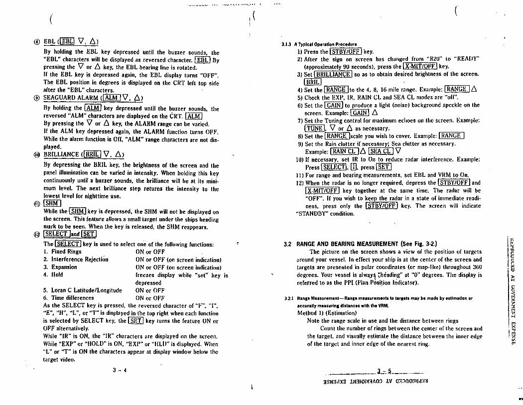
3.4 NAVIGATION WITH THE RADAR
3.4.1 Ob11lnln11 Poalllon fix
The Model R20 Radar is an accurate and reliable navigational aid for determining your ship's position. Figure 3-4 shows examples of alternative methods of using radar sitings from prominent navigational points which can be identified on a chart. A position fix based on two or more navigational points will furnish an accurate fix, especially when the points approach 90 degrees are separated by more than 90° from each other relative to your ship.
3.4.2 Avold1nce Ttchnlquea Colllalon
The moment a new target appears on the screen, its range and relative bearing should be noted. This is best done by putting the target information directly onto plotting sheet or chart.
As in visual observation,. "a constant bearing indicates a collision course."
As soon as a series of plots taken at intervals of 3 minutes indicates a closing range with no significant change in successive bearings, positive course change action should be considered and "The Regulations for Preventing Collisions at Sea" should be observed.
(
. '1\c A IMlllll llAJtGI AACI
"on10 OH CMAIH
t I~ llALlllMI P\01UD ON CMAfllf
• °"' ••frtOI ••c •'-O °"" llAlll .. 0 PlOUlO Ott CH•••
0 •ADA" IUllN 'MltlOH
FIG. 3·4 POSITION FIX METHODS
3 - 10
-..• .._, • •- t " ~· ¥•L-I ~ I '-''' .._ ..... l .
l
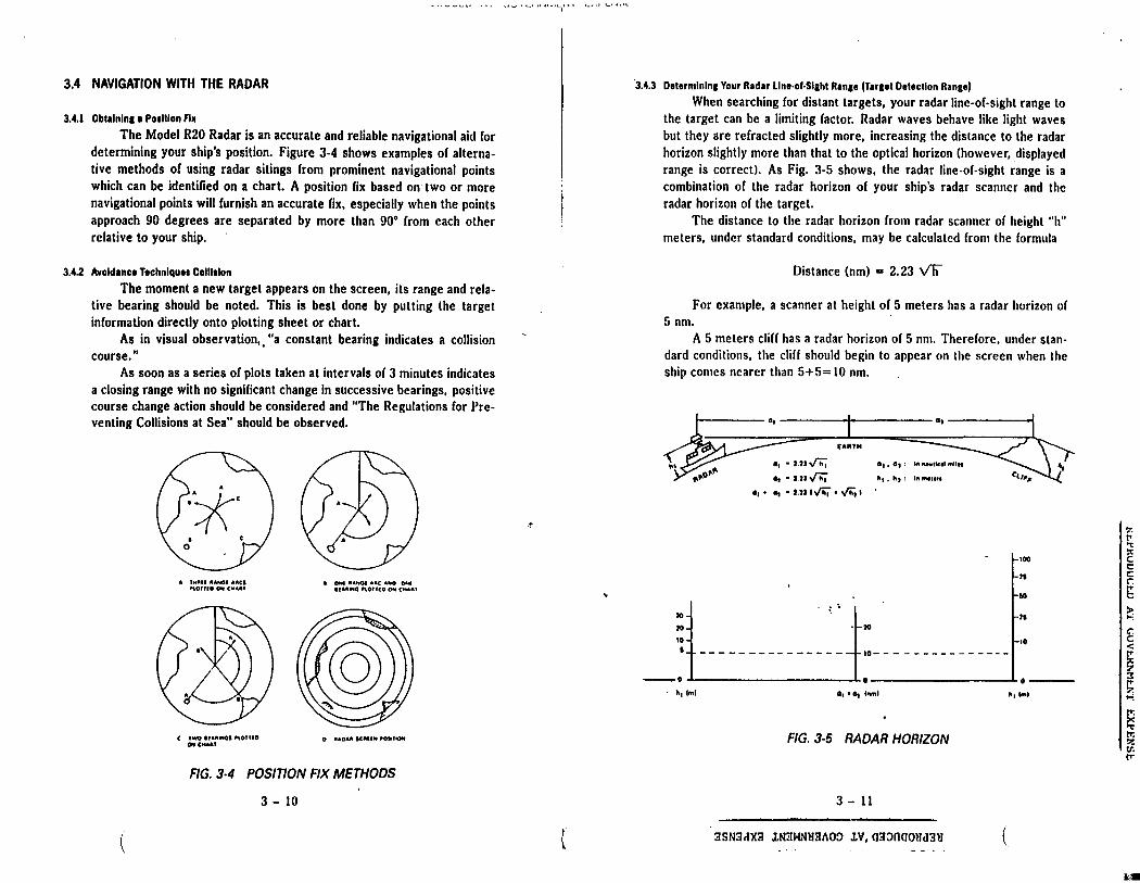
·3.4.3 Delermlnlna Your Rad1r Llne·of·Slahl Ranae (T1r1et Delectlon Ranae)
When searching for distant targets, your radar line-of-sight range to the target can be a limiting factor. Radar waves behave like light waves but they are refracted slightly more, increasing the distance to the radar horizon slightly more than that to the optical horizon (however, displayed range is correct). As Fig. 3-5 shows, the radar line-of-sight range is a combination of the radar horizon of your ship's radar scanner and the radar horizon of the target.
The distance to the radar horizon from radar scanner of height "h" meters, under standard conditions, may be calculated from the formula
Distance (nm) = 2. 23 v'h
For example, a scanner at height of 5 meters has a radar horizon of 5 nm. ·
A 5 meters cliff has a radar horizon of 5 nm. Therefore, under standard conditions, the cliff should begin to appear on the screen when the ship comes nearer than 5+5= 10 nm.
•• EAATH
a,• UJ~ a,, a,,
a, • UJ ,f'h; •1 • •1 '
a, • a, • UJ 1"'4 • y,;; I
100
II
IO
~t--- ----------~ ~t-- h ----- ----- - ~:_ -~.o
IS
• tr. 1 tml .......... "1lml
FIG. 3-5 RADAR HORIZON
3 - 11
3SN3dX3 lN3WNH3AOO lV,03~000Hd3H (
f; "t ~ c t: c:
~ > ....;
t < !'".
~ ~ I"'. ?. ...;
s Ir. :>! v. rr
.,,.
(
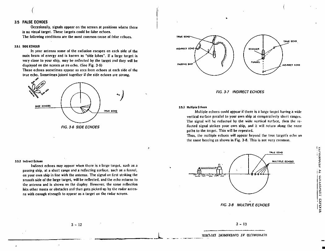
3.5 FALSE ECHOES Occasionally, signals appear on the screen at positions where there
is no visual target. These targets could be raise echoes. The following conditions are the most common cause or false echoes.
3.5.1 SIDE ECHOES
In your antenna some or the radiation escapes on each side or the main beam of energy and is known as "side lobes". Ha large target is very close to your ship, may be renected by the target and they will be displayed on the screen as an echo. (See Fig. 3-6) These echoes sometimes appear as arcs form echoes al each side or the true echo. Sometimes joined together ir the side echoes are strong.
~.if'
;,:,, .
op.,. .,.,.. ~··)
SIDI ICHDES
TRUE ECHO
FIG. 3-6 SIDE ECHOES
3.5.2 Indirect Echoes
Indirect echoes may appear when there is a large target, such as a passing ship, at a short range and a renecting surface, such as a runnel, on your own ship in line with the antenna. The signal on first striking the smooth side or the large target, will be renected, and the echo returns to the antenna and is shown on the display. However, the same renection hits other masts or obstacles and then gets picked up by the radar antenna with enough strength to appear as a target on the radar screen.
3 - 12
r ..
TRUE (CHO
_ _l_ - --··-
SCANNER
INDIRECT ECHO
FIG. 3-7 INDIRECT ECHOES
3.5.3 Multiple Echoes
Multiple echoes could appear ir there is a large target having a wide vertical surface parallel to your own ship at comparatively short ranges. The signal will be reflected by the wide vertical surface, then the renected signal strikes your own ship, and it will return along the same paths to the target. This will be repeated. Thus, the multiple echoes will appear beyond the true target's echo on the same bearing as shown in Fig. 3-8. This is not very common.
TRUE ECHO
MULT.,L( ECHOES
lU ~ .,..,. __ .:;;,,,_ __ _ --- ---
FIG. 3·8 MULTIPLE ECHOES
3 - 13
-~~~~~~
:.ISN::lclX3 lNaWNll3fl0!> J.V O!l:lOOOMct:lll
I:;: : r.: :2
t: c r IT t:
j )> . ..., i C" ,~
Is I.~
0-:
tr. I:>-:
I.;;,
?.: v. (T'
-
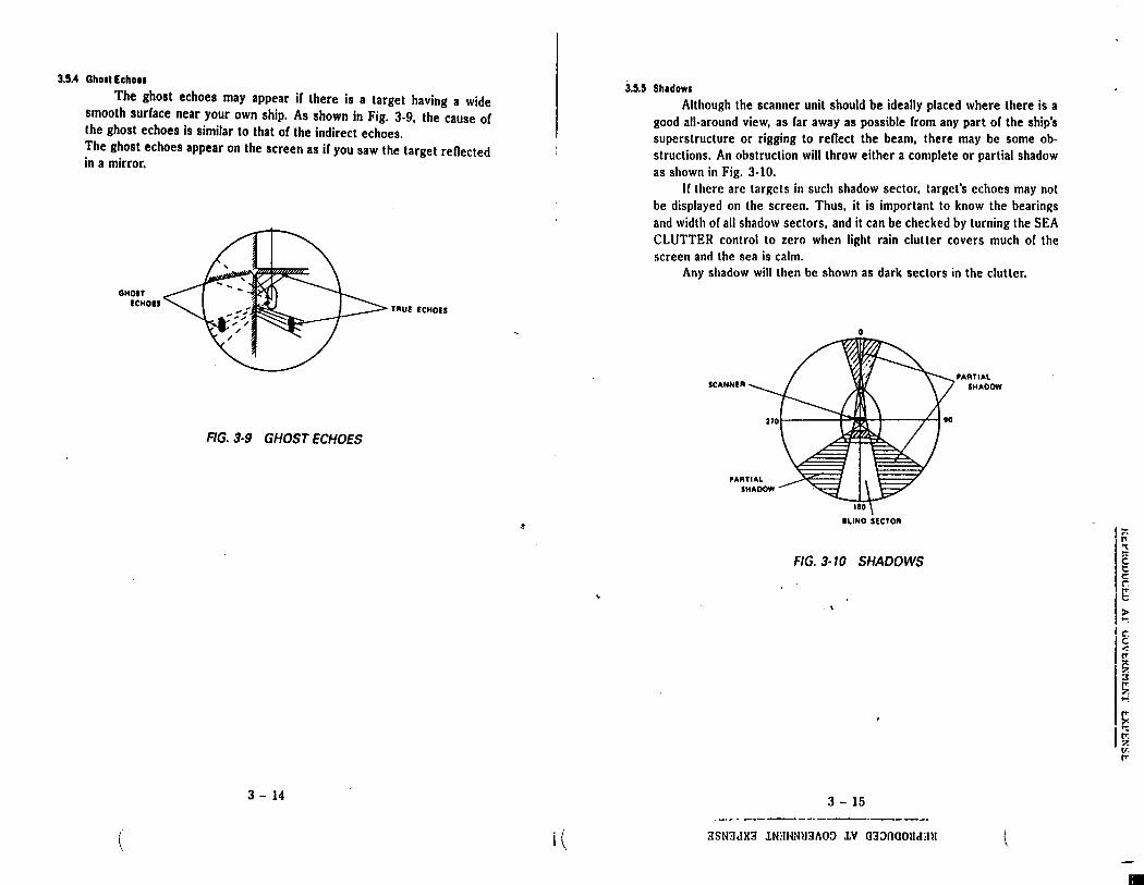
3.!1.4 Ghoat Echo11
The ghost echoes may appear if there is a target having a wide smooth surface near your own ship. As shown in Fig. 3-9, the cause of the ghost echoes is similar to that of the indirect echoes. The ghost echoes appear on the screen as if you saw the target reflected in a mirror.
GHOST ICHOH
(
TAUi ECHOES
FIG. 3·9 GHOST ECHOES
3 - 14
·'
i (
3.!l.!I Sh1dow1
Although the scanner unit should be ideally placed where there is a good all-around view, as far away as possible from any part of the ship's superstructure or rigging to reflect the beam, there may be some obstructions. An obstruction will throw either a complete or partial shadow as shown in Fig. 3-10.
If there are targets in such shadow sector, target's echoes may not be displayed on the screen. Thus, it is important to know the bearings and width of all shadow sectors, and it can be checked by turning the SEA CLUTTER control to zero when light rain clutter covers much of the screen and the sea is calm.
Any shadow will then be shown as dark sectors in the clutter.
0
SC ANNI A
ILINO SlCTOA
FIG. 3·10 SHADOWS
3 - 15
3SN3clX3 lN:IHNH3/\0:> lV 03:l000lld3ll
PAATIAL SHAOOW
(
r.· '"t
~ c
I~ IC':
I~ :7. 3
~ ...,
~
I ~ ?. v. fr
•

(
" .,,
·!
SECTION 4
MAINTENANCE
4.1 USER PREVENTIVE MAINTENANCE Continuous satisfactory operation or the radar can depend on how
well you take care or your equipment. These simple maintenance tips can save you time and money, and help you avoid premature equipment failure.
1) Always keep the equipment as clean as possible. Remove dirt, dust, or water-spray during the boat clean up.
2) Ouring routine ships maintenance, make a thorough inspection or the radar system including the following points: a. Check all hardware for lightness. b. Check for evidence or any corrosion on the scanner unit, display
unit, or its cable and connectors. Clean as required. c. Check the cable connections and terminal strip connections for
cleanliness and tightness. Make sure the wiring is free from charing or abrasions.
. \ '
-------A.-l.. ::tSN'1,tx::i J.m1w~H131\0!> J.V m1:>nam1,rnu
I ti; 'C
~ t:: c: r. tr. t::
1~ .....,
G": c < !Tl ::0 z :t !Tl 7. >-!
Q "O !Tl ::-. Ill !Tl
4.2 SCANNER UNIT Set the safety switch (SlOl) of the Scanner Unit to OFF before
working on the radar Scanner.
CAUTION: The safety switch of this radar only stops antenna rotation. The transmitter will operate when the radar is turned to ON. Avoid allowing the array to point towards anyones' eye level during ser· vice work.
4.2.1 R1dome
Wipe the surface of the Radome with a clean, soft cloth. Remove any paint, dirt, or caked salts. Heavy deposits of dirt or caked salt on the surface of the Radome can cause a considerable drop in the radar's performance. Avoid using chemical cleaners of solvents. Alcohol is preferred or light detergents as a cleaning agent.
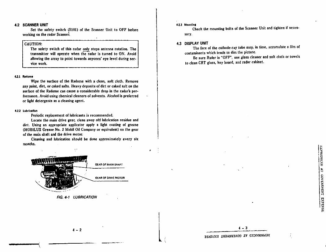
4.2.2 Lubrlc1tlon
Periodic replacement of lubricants is recommended. Locate the main drive gear, clean away old lubrication residue and
dirt. Using an appropriate applicator apply a light coating of grease (MOBILUX Grease No. 2 Mobil Oil Company or equivalent) on the gear of the main shaft and the drive motor.
Cleaning and lubrication should be done approximately every six months.
GEAR OF MAIN SHAFT
GEAR OF DRIVE MOTOR
FIG. 4· 1 LUBRICATION
4 - 2
\
.t
l (
4.2.3 Mountln1 Check the mounting bolts of the Scanner Unit and tighten if neccs·
sary.
4.3 DISPLAY UNIT The face of the cathode-ray tube may, in time, accumulate a film of
contaminants which tends to dim the picture. Be sure Radar is "OFF", use glass cleaner and soft cloth or towels
to clean CRT glass, key board, and radar cabinet.
4 - 3 -----------------3SN31IX3 J.N3HNll3i\O~ J.V 03:.lfl00l1"3ll (
I~ I': ~
1C 't;:; lg I~
~ Cl c < fr, :io z :?: J'T1 '7.
""' ~ .,, t'1 7. Ill rn
-

-~
(
SECTION 5
ADJUSTMENT AND FAULT FINDING
5.1 ADJUSTMENT
5.1.1 Adjustment for Replacln1 Components
Although the radar is delivered adjusted for optimum performance, it may be necessary to make adjustments after a major component has been replaced or if a fault is suspected during operation.
NOTE
trnPLACEMENT ITEM ADJUSTMENT REQUIRED See Sect. #
Magnetron VI Tuning 5.3
MIC Frontend E301 Tuning 5.3
Cathode-ray tube V501 Adjusting centering magnet Display PCB Adjusting intensity 5.3
Adjusting focus
SHM Unit S102 Bearing Alignment
... \
-----···-5..::_.L __ 3SN3cJX:.f J.N:IHNM3AO~ J.V 03:lnom1.1:ni
~ "t
~ t:: c: r. ~ > ...;
~ < fr. ~ z :t ~ ?. ....;
~ :><
;,~
:<'!: v . ...,
-

l502 RV504
FIG. 5-1 DISPLAY PCB
5 - 2
(
RV505 (FOCUSJ
-~
i
l(
1) Intensity adjustment (See Fig. 5-1) a. Remove the cover from Display Unit. b. Set BRILLIANCE for maximum level. c. Adjust RV504 on Display PCB, so that PPI is of suitable bright
ness. 2) Focus adjustment (See Fig. 5-1)
a. Remove the cover from Display Unit. b. Adjust RV505 on Display PCB so that the sweep line, rings, and
targets on the screen are as small and clear as possible. 3) H. HOLD
Adjust RV503 on Display PCB so that horizontal screen is kept in sync.
4) H. SIZE and V. SIZE Adjust L502 and RV501 on Display PCB so that the rings are found. Note: With a ruler, adjust for equal diameters N/S E/W.
5) V-LINEAR Adjust RV502 on Display PCB so that the rings are found.
6) Main Board PCB Adjustment (See Fig. 5-2) a. Remove the hole cover for adjustment. b. Proceed with adjustment as required on the Main PCB (PCl and
PC2) as follows. 6.1) Interlace adjustment (PCl)
Adjust RVl so that the TV horizontal lines are finely interlaced. 6.2) Relative Bearing Alignment (PCl)
Adjust RV2 (BRC) and RV3 (BRF). (See Section 2.4.3) 6.3) GAIN adjustment (Comparator set: PC2) a. Set GAIN control at the maximum, turn IR "ON". b. Adjust RVl until some back ground speckle is present on the
screen. 6.4) 0 nm Adjust1f!ent (PC2)
Adjust RV2. (See Section 2.4.4) 6. 5) Tuning Adjustment (Pt2) a. Set the Tune control at the center. b. Adjust RV3 until the strongest echoes are displayed. 6. 6) Alarm (PC2) a. Set the RANGE to 0.25 nm b. Press ALARM key and set alarm zone within 0.25 nm. c. Set GAIN control until the ec~oes are displayed in the alarm
zone. d. Adjust RV4 until to obtain desired loudness.
5 - 3 -~~~~~-
3SN3dX3 lN3HNM3A09 lV aa~naOHd3U (
:r. l''. ~
E t c r: ~ >: ...., C". c < tr. :it z :? tr. z ...;
. !:'. i;;, 1 :>:
tll fr,
( I ( (
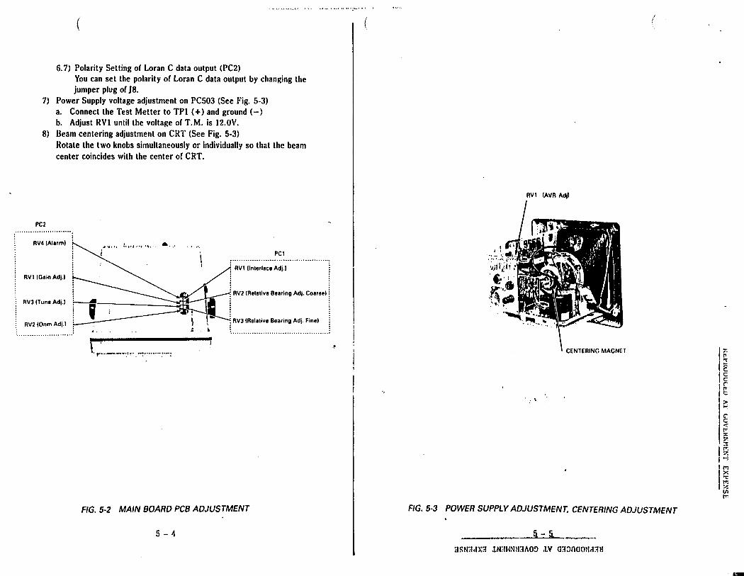
6. 7) Polarity Setting of Loran C data output (PC2) You can set the polarity of Loran C data output by changing the jumper plug of J8.
7) Power Supply voltage adjustment on PC503 (See Fig. 5-3) a. Connect the Test Metter to TPl ( +) and ground (-) b. Adjust RVl until the voltage of T.M. is 12.0V.
8) Beam centering adjustment on CRT (See Fig. 5-3) Rotate the two knobs simultaneously or individually so that the beam center coincides with the center of CRT.
PC2
RV4 IA1arml ...... PCI
RV1 (lnlerlace Adj.I RV1 !Gain Adj.I
RV2 IRelalive Bearing Adj. Coarse) RVJ ITune Adj.I
RV2 IOnm Adj.) RVJ fRelalive Bearing Adj. Finel :
·························
r ,.-----.. ··-. ~ ......... -:
FIG. 5-2 MAIN BOARD PCB ADJUSTMENT
5 - '1
RV1 (AVR Adjl
CENTERING MAGNET
\
FIG. 5-3 POWER SUPPLY ADJUSTMENT, CENTERING ADJUSTMENT
~ :rnmt.txtl lN'.·IWNM::ti\O!) .t.V O:l::>namt.t::tll
I~ I 't
1€ I~ .r • r-1 t I )>
....
~ < IT'. :x: 7.
I.~ 7. i..;
Is .... :'. VI I"'
-
5.2 TROUBLE·SHOOTING
5.2.1 General
While the R20 Radar is a highly reliable system, early detection of component fatigue can be spotted during regular operational checks.
When a problem is observed, corrective service should be arranged to avoid failure at critical times at sea.
5.2.2 Faull Flndln1
(1) Regular operational checks (preventative maintenance) The electrical performance of the equipment should be evaluated at periodic intervals by qualified Raytheon Technicians and the results recorded. Changes in test results may indicate an aging or failing component. Table 5.1 provides a check list of items. Whenever an abnormal result is obtained from a test, appropriate corrective maintenance should be employed to prevent serious dam· age or failure modes.
CAUTION: In making checks, be alert to the high voltage points existing throughout the equipment.
(2) Fuse
A ruse seldom blowns out without some cause. Even if a fuse is merely replaced and does not blow again, it still may be necessary to make further checks of the circuits associated with the fuse. Table 5.2 shows a table or fuses employed in the equipment.
(3) Fault finding procedure
Often the display on the CRT can help indicate which major circuit is at fault. The next step is study the block diagram (Fig. 104) to obtain an idea as to obtain an idea as to which stages require checking, in what order, and what additional tests such as controladjustments may be necessary. It may be found quicker to check-out the equipment according to the trouble shooting guide (Table 5.3). In general, the causes of troubles frequently encountered include abnormal resistances, intermittent variable resistors, switches, and relays and shorted crystal diodes. In the following fault finding procedure, it is assumed that only a VOM is available; the use or an oscilloscope simplifies the procedure, and may prove necessary in some cases.
5-6
\
.!
Unit
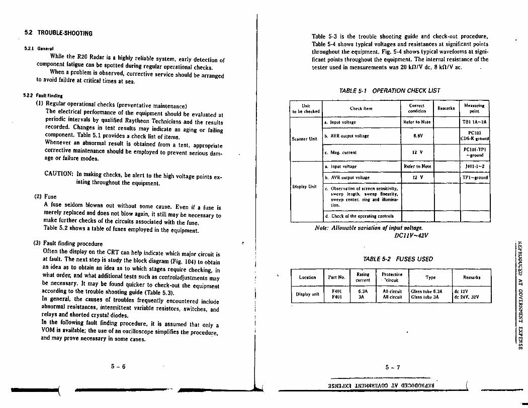
Table 5·3 is the trouble shooting guide and check-out procedure, Table 5·4 shows typical voltages and resistances at significant points throughout the equipment. Fig. 5·4 shows typical waveforms at signi· ficant points throughout the equipment. The internal resistance of the tester used in measurements was 20 Ul/V de, 8 kfi/V ac.
TABLE 5· 1 OPERATION CHECK LIST
Correct MeasurinR to be checked
Check item condition Remarks
point
a. Input voltaRe Reier lo Note TIH IA-2A
b. AYR output voltage 6.8V PCIOI
Scanner Unit CIJ6-K Rround
c. Mag. current 12 v PCtol-1'1'1 -around
a. Input voltage Refer to Note 1401-1-2
b. AVI( output voltage 12 v Tl' I-around
IJisplay Unit c. Observation ol screen sensitivity, sweep length, sweep linearity, sweep center, rina and illumina· lion.
d. Check ol the operating controls
Nole: Allowable variation of input voltage. DCJJV-42V
TABLE 5·2 FUSES USED
Location Part No. Rating l'rolecti\·e
Type Remarks current "circuit
Display unit F401 6.3A All circuit Glass lube 6.JA de 12V F401 3A All circuit Glass tube :IA de 24V, 32V
5 - 7
3SN3clX3 .1.N3WNM:IAO:J lV <1::t:l0<10lld3ll \
I·-;:
I'• "C s t:; c: r. l;j
~ 8 < l"I
"' z :r l"I '?. ...,i
1.§
7. Ill tr!
-

·' •IUUUL.UJ A I uU\/l:.HNMt:.N I I
(
TABLE 5-3 TROUBLE SHOOTING GUIDE
Trouble Remedy
I. Does not start at Check: OPERATE switch o Blown ruse F40l. to STBY. o Check input power circuits.
o Fault or contact on S401. o Fault or power supply circuit on PC503. o Fault or contact on connector or PC503. o Fault or rectifier diodes on PC503.
2. Scanner fails to Check: rotate. o Fault or SIOI. (Safety Switch OFF)
o Fault or contact on terminal boards. ~
o Fault or MIOl (Commutator and brushes.) o Fault or drive mechanism.
3. Scanner rotates Rotation or MlOl or fault or connection but rotation or between MIOl sweep is abnormal Check:
o Fault or motor encoder (DP). o Fault or MlOl. o Fault or main circuit for the Display Unit.
4. No picture on the Fault or CRT display unit or its supply voltages. screen. Check:
o Open heater or CRT or blown ruse F501 on display PCB.
o Fault or contact on CRT socket. -~
o Fault or contact on CRT cap. 0 fault or video circuit
5. Only horizontal There may be fault in vertical sweep line screen. generator, amplifier circuits and deflection coil.
Check: o Fault in vertical sweep generator, amplifier
circuit
6. Incorrect sweep o Adjust MT401 o Start of sweep o Adjust horizontal or vertical hold.
is not centered o Adjust vertical length and linearity. on the screen. o Adjust height as necessary.
o Markers are oval.
5 - 8
J~I.
Trouble Remedy
7. Range rings on Faulty circuit between IF amplifier of the screen but no receiver unit and input circuit or display unit video noise and no amplifier. echoes: Check:
o Fault or GAIN, STC control settings. o Fault or receiver unit. o Fault or contact on terminal boards and
connector. o Fault or GAIN, STC circuit on PC2.
8. Noise and range H no transmission is present, check the rings on the screen modulator and magnetron. but no echoes. Check: H transmission appears to be present as
indicated by the correct MAG. I reading on Tester. PCIOl TPl = 12 voe
o Failure or Local Oscillator tuning.
H transmission appears to be present, carry out the Local Oscillator tuning procedures and check the MIC o Fault or MIC Mixer.
H no transmission is present, o Whether the lead wire to magnetron is
contacted to chassis. o Fault of magnetron.
9. Poor sensitivity. Check: Oim echoes. o Reduction or transmitting output power.
o Fault or magnetron. --. Che'ck or MAG. I reading on PCIOI-TPl.
o Fault or MIC Frontend. o Fault or CRT. o Failure of Local Oscillator tuning. o Failure or FOCUS adjustment. o Failure of INTENSITY ADJ. o Fault of video amplifier circuit on PC2. o Fault or receiver unit.
5-9
:;JSN;},JX:.t J.N3HNlJ3110n lV o:.t:maou.t:.tN
~ ['IJ "ti ~ 0 0 c: n a ~ C") 0 ~ M :<I 7. :< M 7. >-I
~ "ti M ?. 11'1 tr1
-

Trouble Remedy 10. NO VRM or Check:
VRM cannot be o Fault of S401. controlled. o Fault of main circuit.
13. NO EBLor Check: EBL cannot be o Fault of S401. controlled. o Fault of main circuit.
14. No alarm zone Check: marker, cannot o Fault of S401. be controlled or no o Fault of main circuit. alarm sound. o Fault of Buzzer BZI.
Table 5.4 shows typical voltage and resistances at significant points throughout the equipment. Fig. 5-4 shows typical wave forms at significant points throughout the equipment.
TABLE 5.4 TYPICAL VOLTAGES AND RESISTANCES
(A) Inter-unit terminal board
Nott: Rtsistanct mtasurtmtnls shall bt madt u11dtr tht /ollowi11g co111fi. lions:
I POWER I switch-OFF I ~101 l.oN.
Rtsistanct valut shall bt measured btlween measuri11g poi11t a11d ground unless otherwise specified, and negative ltn11i11al of the tester is grounded as a rull.
Tht ltsltr used/or this mtasurt111t11t is 20 kntV de, 8 kOIV ac. Voltage mtasurtment shall bt made rmder tht /ollowi11g co11ditio11s: I POWER l switch-ON, l RAIN CLUITERl-min, I GAIN I-max, I SEA CLUTIER I-min. Ship's pow1r supply is de 12V.
5 - 10
'.,_, • l I" "••LI• I
.!
Measuring Resistance Voltage (V)
Point (0) 0.25 - 2. 4 - 16 Remarks
(nm) (nm)
TBl 1A-2A 4.5xIO 10-112 10-42 DC120 V 1B-2A 6Xl0 9.6 9.5 DC 12 V
BZ llOx 10 5.1 5.1 DC 30 V GS 19X 10 6.0 6.0 DC 12 V 33 7.5xl0 22.2 22.2 DCI20 V
VD-VDR 5.5x 10 -0.135 -0.135 DC0.3 V BP 26Xl0 2.6 2.6 DC 30 V Tl lOXlO 0.03 0.03 DC0.3 V Pl 6.5x 10 13 13 DC 30 V
(B) lfosistances al inter-unit connector without connection of cables.
Note: Refer lo Note give11 i11 item (AJ.
SCANNER UNIT DISPLAY UNIT Measuring Point Resistance (fl) Measuring Point Resistance ({})
TBIOl IA oo x IUK J402 1 oo x lOK 2A oo x lOK 2 oo x lOK lB oo x lOK 3 12 x 10 BZ oo x lOK 4 0 x 10 GSI{ 0 x IO 5 0 x 10 GS 500 x 10 6 5 x 10 33 oo x lOK 7 100 x 10 VD oo x lOK . , 8 oo x IOK VDR 0 x 10 9 oo x lOK BPR 0 x 10 10 100 x 10 BP 24 x 10 11 18 x 10 TIR 0 x 10 12 0 x 10 Tl 30 x 10 13 lK x 10 Pl 40 x 10 . 14 0 x 10
15 00 x IOK 16 6 x 10
5 - 11
3SN3.IX3 J.N3HNll3AO~ J.V mr:maOUd3U
~ "t z e c: r. I~ ~ r:: c < tr. :0 7. 3: l'TI
~
~ 'U l'I ?. t/I I"
rim
•
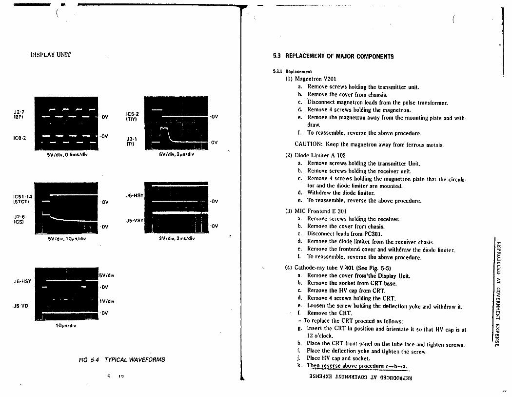
DISPLAY UNIT
J2·7 (BP)
IC8·2
IC61·14 ISTCTI
J2·6 (GS)
J6·HSY
J5·VD
6V /div, 0.6ms/div
6V/div, IOµs/div
·OV
·OV
·OV
·OV
5V/div
·OV
IV/div
iiiiiiiiiii·OV 10µs/div
IC5·2 ITIYl
J2·1 (Tl)
J5·HSY
J6-VSY
6V/div, 2µs/div
2V/div, 2ms/div
FIG. 5-4 TYPICAL WAVEFORMS
c; 1?
-ov I
·OV
·OV
5.3 REPLACEMENT OF MAJOR COMPONENTS
5.3.l Replacement
(1) Magnetron V201 a. b. c. d.
Remove screws holding the transmitter unit. Remove the cover from chassis. ·Disconnect magnetron leads from the pulse transformer. Remove 4 screws holding the magnetron.
(
e. Remove the magnetron away from the mounting plate and withdraw.
r. To reassemble, reverse the above procedure.
CAUTION: Keep the magnetron away from ferrous metals.
(2) Diode Limiter A 102 a. Remove screws holding the transmitter Unit. b. Remove screws holding the receiver unit. c. Remove 4 screws holding the magnetron plate that the circula
tor and the diode limiter are mounted. d. Withdraw the diode limiter. e. To reassemble, reverse the above procedure.
(3) MIC Frontend E 301 a. Remove screws holdi.ng the re~eiver. b. ({emove the cover from chasis. c. Disconnect leads from PC301. d. Remove the diod~ limiter from the receiver chasis. e. lkmove the frontend cover and withdraw the diode limiter. f. To reassemble, reverse the above procedure.
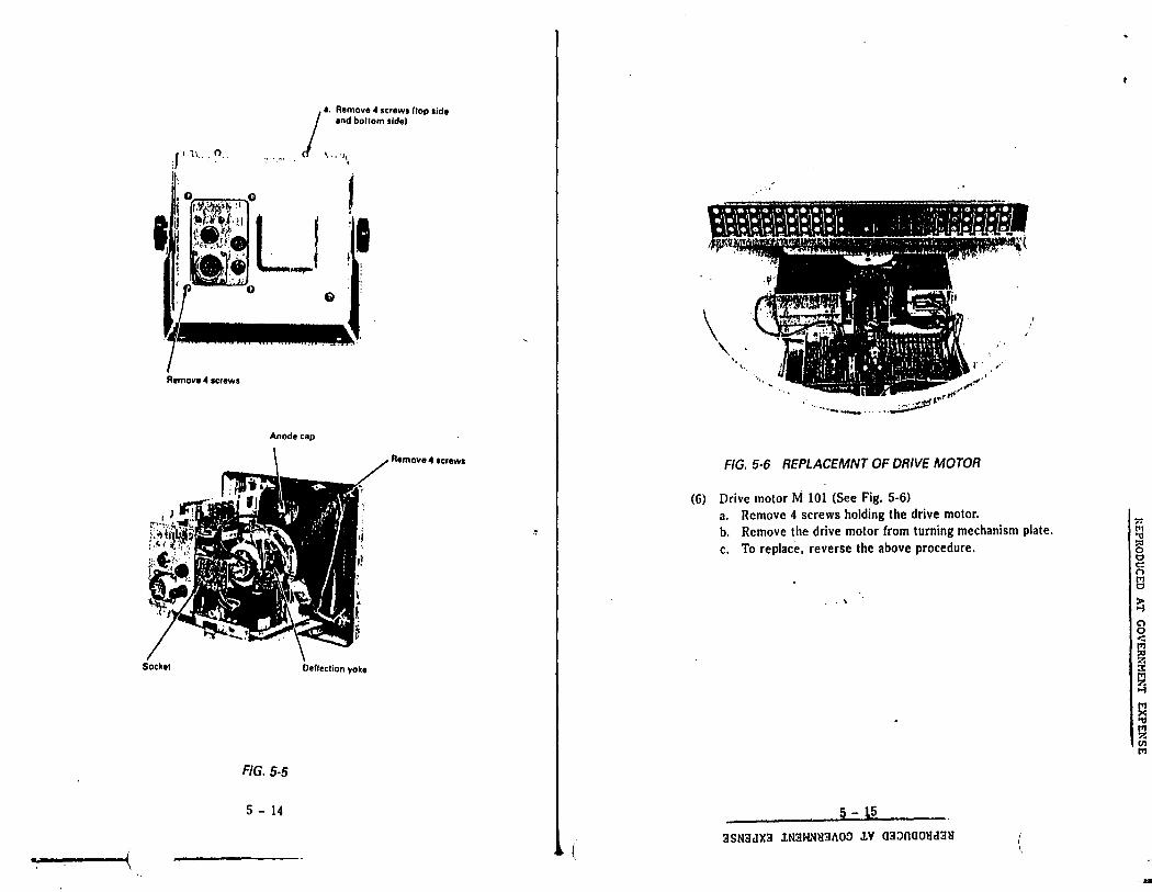
(4) Cathode-ray tube V '401 (See Fig. 5•5) a. Remove the cover trom~he Display Unit. b. ({emove the socket from CRT base. c. Remove the HV cap from CRT. d. Remove 4 screws holding the CRT. e. Loosen the screw holding the deflection yoke and withdraw it. f. Remove the CRT. - To replace the CRT proceed as follows: g. Insert the CRT in position and orientate it so that HV cap is at
12 o'clock. h. Place the CRT front panel on the tube face and tighten screws. i. Place the deflection yoke and tighten the screw. j. Place HV cap and socket. k. Then reverse above procedure c-+b-+a.
3SN3clX3 J.N3WNH3i\O:J J.V 03:JnOOlld3ll
r.: "C :e c c c: r. tl ~ g < !Tl ;o z 3: !Tl 7, >-I
s !Tl '7. (II trl
-
·- (
J' h .. o.
lh
Remove 4 screws
Socket
/
1. Remove 4 screws flop tide and bottom sldal
( ' .. J'
G
' , ·'1 , ..
Anode cap
Remove 4 1crew1
Deflection yoke
FIG. 5-5
5 - 14
\ ' '· '··
·1,, J"
... ··- "' ........ -............ . ........ ~t""r
·-····~
FIG. 5·6 REPLACEMNT OF DRIVE MOTOR
(6) Drive motor M 101 (See Fig. 5-6) a. Remove 4 screws holding the drive motor. b. Remove the drive motor from turning mechanism plate. c. To replace, reverse the above procedure.
. \
5--:.~--3SN3dX3 iN3HNH3hO~ iv 03~naOHd3H (,
f;; .,, ~ ti c: n !j
~ 8 -:: "' :a z :i::
8 a "' z VI tTI
-

• ia:.l:'lWUUC.:J::U AT GOVERNMENT EXPENSE
2.4 INITIAL OPERATION AND CHECKOUT
2.4.1 Inspection After the Installation
After completing the installation and prior to energizing the equipment, it's a good idea to recheck that all the steps of the installation are completed in accordance with the instructions.
In particular, inspect to insure that the cables were not accidently crimped or. damaged and that the ships input voltage is connected correctly; that the mounting bolts of the scanner unit are tight; the cable gland is tightly sealed at the Scanner Unit, that the antenna connections are correct, and the cable shield is connected properly to RF ground.
2.4.2 Operational Checkout .•
Activate the power circuits to the radar and swi;ch the radar into standby (STBY). After approximately 90 seconds the "'READY" will be displayed on the CRT.
If you are unfamiliar with the operating controls of this radar, please take a few moments to familiarize yourself by reviewing the instructions in Chapter 3 Operation.
Press the X-MIT switch to "ON" and observe presence of radar targets on the screen. Check the operation of the Range, selection keys for each range scale. Observe that the sweep is the correct length and has the proper number of range rings. Observe that the range markers are focused properly.
Operate the ... , B.;...R_I_L....,I key. Check for multiple picture intensity level operation.
After approximately 10 minutes of operation, check the TUNE, 'V, or D. keys for maximum target returns occur at the center of the TUNE level range.
If readjustment of the Display Unit is required follow the instructions for alignment in section 5 (pages 1 to 5) adjustment and faultfinding.
POST INSTALLATION SET UP ADJUSTMENTS
2.4.3 Relative Bearing Alignment (RV2 and RV3 on PCl)
This alignment should be carried out for safety once the installation is completed. If the ship is moored, proceed as follows: (1) Identify a suitable target (e.g., ship or buoy, etc.,) preferably be
tween 1 and 2 nm range on the screen.
2 - 11
l I

PC2 :··························: l RV4 (Al1rml ' ! PCI
I ........................................... RVI (lnlerlace Adj.I I RV1 (Gain Adj.I
RV2 (Relalive Bearing Adj. Coarsel
\ RVJ (Tune Adj.I
l RV2 (Onm Adj.I
: ••••••••..••••••••.•••• , •• ! 1 ......................... ---l \. • .. I •· _J
r . ..... -'····4•· ....... -:-::
RVJ (Relalive Bearing Adj. Finel
............................................
FIG. 2· 10 SETUP ADJUSTMENT LOCATIONS
(2). Remove the rubber seal covering the display adjustments (top of dis-play cabinet).
(3) Set the EBL marker on the known target. (4) Set RV3 (BRF) at its mid position (BRF=Bearing, Fine Adj). (5) Press the [SET] key until the buzzer sounds and the on-screen words
"BEARING ADJUST" appear. (6) Rotate the coarse bearing adjustment RV2 (BRC) as necessary until
the EBL marker matches the observed bearing to the target to within ± 10° and the beeper sounds continuously.
(7) Use the fine adjust RV3 to set the bearing to within ± 1° on the radar display.
(8) Upon completion, press the [SET] key until the words "BEARING ADJUST" disappear, to restore the normal display mode.
2 - 12
(
·~
j(
2.4.4 0 nm (Zero nm) Adjustment (see Fla. 2·10.) This is a radar system timing adjustment. Incorrect timing is most
noticeable on the 1/4 NM scale. It can be checked and set in the following manner. (1) Locate a straight dock, seawall or bridge on the radar display at 114
NM scale. (2) Adjust RV2 (0 nm Adj) in the internal adjustment panel so that the
object is straight on the display.
Pushing - Oi1pl1y liming t1rly Pulling - D11pl1v timing 1111 Norm1I
2.4.5 R1d1r Gain Adjustment
The radar gain can be checked to be sure that "full gain" is available for proper display in the following manner: A. Set radar gain to maximum level as indicated by the bar graph. B. Set radar onto maximum range scale. C. Make sure "FTC" and "STC" are at minimum level. D. Turn "ON" the "IR" control. E. Set RVl (gain preset) for background noise speckle on the CRT.
ALARM VOLUME Turn on Alarm with I ALM I key. Hold I ALM I key depressed until
ALM character in upper left of display reverses to block form. Use 6. or 'V key to move ring to contact targets.
Adjust RV4 alarm volume for desired sound level.
2 - 13
3SN3dX3 lN3HNU3AO~ lV 03JOOOUd3U (
f1~ '"C
'E 'C ;c . ("'. . .,, •c
l ): ..., I
18 ; .-:: I tr. ';.:
i~
I'~
...;
d.'.1 ~
'M ''7. v: ..,.,