rapid tooling manufacturability evaluation using fuzzy...
TRANSCRIPT

JUNE 2005
Technical paper submitted to the International Journal of Production Research
Rapid tooling manufacturability evaluation
using Fuzzy-AHP methodology
NAGAHANUMAIAH Scientist, Central Mechanical Engineering Research Institute, Durgapur, India
B. RAVI * Associate Professor, Mechanical Engineering Department,
Indian Institute of Technology, Bombay, India [email protected]
N.P. MUKHERJEE
Scientist, Central Mechanical Engineering Research Institute, Durgapur, India [email protected]
Word count: 5002 *CORREPONDING AUTHOR Prof. B. Ravi Mechanical Engineering Department Indian Institute of Technology Powai, Mumbai - 400 0076 Tel: (+91-22) 2576 7510 Fax: (+91-22) 2572 6875 E-mail: [email protected]
Abstract Rapid tooling (RT) processes driven by rapid prototyping (stereolithography and selective laser sintering) can reduce mold development lead-time by 50% or more, though there are certain limitations in terms of mold materials, accuracy, and surface finish. This paper presents a systematic approach for manufacturability analysis of molds produced by rapid tooling methods, based on three aspects: mold feature manufacturability, secondary elements compatibility, and cost effectiveness. The geometric features of functional elements of the mold (core, cavity, side core, etc.) are

2
evaluated for manufacturability using fuzzy-analytic hierarchy process (Fuzzy-AHP) methodology. The secondary elements of mold (parting surface, ejectors, cooling lines, etc.) are checked for compatibility with RT mold properties (machinability, wear resistance, surface evenness, etc.). Finally, the cost of RT mold is estimated using a cost model based on cost drivers and cost modifiers, and compared with that of a conventional mold. The methodology has been demonstrated with an experimental mold. It is useful not only for RT mold process selection, but also for identifying minor modifications to a mold design to improve its manufacturability and economy. Keywords: Rapid Tooling, Manufacturability Evaluation, Fuzzy-AHP, Injection Molding.
1.Introduction
In the last few years, several rapid tooling methods, based on rapid prototyping technology, have been explored and enabled lead-time reduction of 50% or more in injection mold development. Examples include SLA-AIM based on stereolithography, and DMLS (direct metal laser sintering) based on selective laser sintering process. Rapid tooling processes are mainly being used to manufacture the functional elements: core, cavity and side cores, which impart the desired geometry to the incoming melt (figure 1). The secondary elements of the mold such as the feeding system, ejection system, side core actuators and fasteners, along with a mold base set, are usually procured as standard accessories from vendors.
Figure 1: Construction of a typical injection mold

3
The RT processes are being continuously improved in terms of accuracy, surface finish and mold strength (mold life), leading to a large number of present and emerging choices for mold developers. They need a systematic approach for selecting the most appropriate rapid tooling process, driven by an objective evaluation of mold manufacturability with respect to a given process. Manufacturability evaluation involves measurement of relative ease of manufacturing. Design for manufacturability (DFM) uses documented design guidelines to determine if a part can be manufactured with acceptable manufacturing quality, cost and time. Several researchers have reported their work on material and process selection, and analysis of specific manufacturing processes such as machining (Gupta, et al.,1995), milling (Krishnan, et al.,1997), sheet metal (Wang, et al., 1997; Mukherjee, et al., 1997), powder metallurgy (Dissinger, et al.,1995), and injection molding (Chen, et al., 2003). The manufacturability evaluation can be carried out at two levels (Prashanth, et al., 2003; Zhao and Shah, 2005). A high-level evaluation is mainly aimed at selection of the manufacturing process using parameter matching, case-based reasoning (comparison with past designs using group technology), and rule based expert systems. Detailed manufacturability evaluation is usually performed for a selected process using heuristics, analytical methods, and plan based methods. Manufacturability evaluation of near net shape processes such as plastic injection molding involves manufacturability of tooling (dies/molds) also, in addition to the part. Technical literature related to design for rapid tooling and decision making approaches used in manufacturability evaluation are discussed next. 2. Previous and Related Work The main motivation underlying RP application in mold development is to minimize the lead time (especially for complex shapes), coupled with the advantage of saving expensive mold material, which otherwise has to be removed by machining processes. More than 25 RP-based tooling development processes are available today, though many of them are still maturing and their capabilities are not fully investigated. This may lead to under-utilisation of the capabilities of a selected process, or in extreme cases, to incompatibility between the process capability and mold requirements. Selecting an appropriate process for mold development is therefore critical to meet the desired requirements and derive the maximum benefit from the new processes. A few researchers have even highlighted the need for a ‘rapid intelligent tooling system’ for selection and evaluation of RT process (Kochan, et al., 1999), though very few attempts appear to have been made in this direction. For example, a rule-based approach has been proposed for selecting rapid tooling processes, driven by 180 rules covering four widely-used RP processes (Kaschka, et al., 2002). Some work in design for rapid tooling has been carried out by researchers at Georgia Institute of Technology. They developed geometry based decision templates to formulate the product design requirements using compromise decision support approach for SLA-AIM tooling manufacturability evaluation (Chen, 2001). Harris

4
studied the effect of direct SL resin mold on part quality and shrinkage (Harris, et al., 2003). Coupled thermo mechanical FEM analysis was used to investigate mold expansion and percentage of crystallization, to generate the mold design guidelines for its manufacturability (Harris, et al., 2004). Arni studied the manufacturability of parts in solid freeform fabrication processes, by identifying the optimal build direction to meet the desired flat tolerance (Arni, et al., 2001). In general, manufacturability evaluation has been treated as a multi criteria decision problem, for which Analytic hierarchy process (AHP) and fuzzy multi criteria decision making (FuzzyMCDM) techniques are widely used. Triantuphyllou evaluated five fuzzy multi criteria decision making methods (fuzzy weighted sum model, fuzzy weighted product model, fuzzy AHP, fuzzy ideal AHP, and fuzzy TOPSIS) based on two evaluation criteria: consistency and stability of results (Triantuphyllou, et al., 1996). He found that fuzzy ideal mode (revised) AHP is better than other fuzzy decision making methods, when the problem is complex with a large number of attributes. In a more recent investigation, Jiang developed a fuzzy decision model to integrate multi-level, multi-goal requirements of total product life cycle at early product design stage (Jiang, et al., 2003). He used activity based costing (ABC) for decisions on manufacturing economy. Ong developed fuzzy AHP based computer aided design for manufacturability (DFM) system for rotational parts (Ong, et al., 2003). Here fuzzy representation was used to establish different manufacturability index based on part features, clamping, and support. In this, AHP was used to assign manufacturability index weights for part features. In summary, there is a growing demand for developing, selecting and analyzing rapid prototyping applications for tooling development, hereafter referred to as Rapid Tooling (RT). The selection of the appropriate RT process based on manufacturability evaluation can reduce expensive tooling iterations. Among various decision-making methods, fuzzy AHP has been found to be superior to others, and its application to RT development, especially manufacturability evaluation, appears to be promising. This has however, not been explored so far, and has been taken up in the present investigation. 3.Rapid Tooling Manufacturability Evaluation
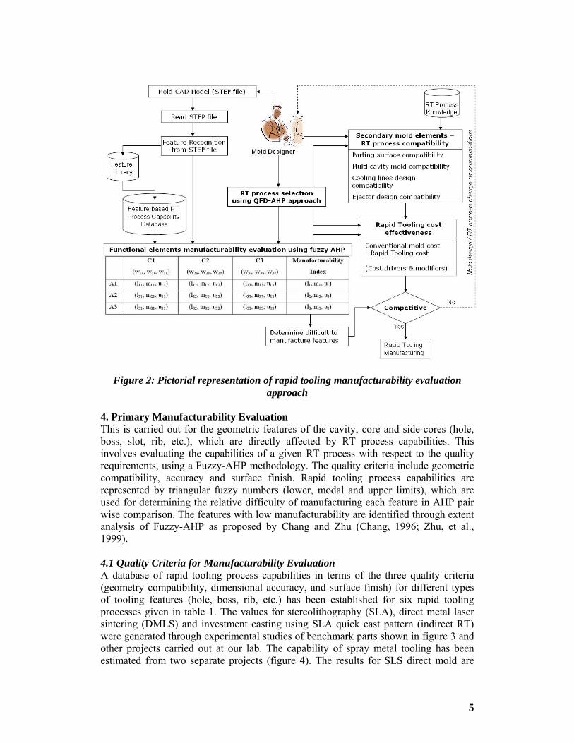
The proposed approach to RT manufacturability evaluation comprises three steps: (1) primary manufacturability evaluation of functional tooling elements: cavity, cores and side cores based on their geometric features, (2) compatibility of secondary elements of tooling (parting surface, ejectors, cooling lines, etc.) with RT mold properties, and (3) cost effectiveness of RT mold (figure 2). The evaluation provides useful information to the mold developers to take decisions regarding process change and/or mold redesign. The three steps are discussed in detail in the following sections.
5
Figure 2: Pictorial representation of rapid tooling manufacturability evaluation approach
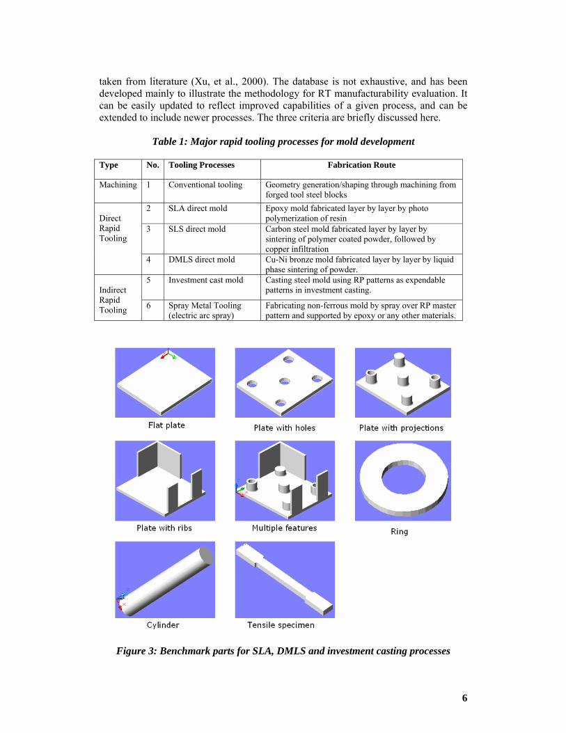
4. Primary Manufacturability Evaluation This is carried out for the geometric features of the cavity, core and side-cores (hole, boss, slot, rib, etc.), which are directly affected by RT process capabilities. This involves evaluating the capabilities of a given RT process with respect to the quality requirements, using a Fuzzy-AHP methodology. The quality criteria include geometric compatibility, accuracy and surface finish. Rapid tooling process capabilities are represented by triangular fuzzy numbers (lower, modal and upper limits), which are used for determining the relative difficulty of manufacturing each feature in AHP pair wise comparison. The features with low manufacturability are identified through extent analysis of Fuzzy-AHP as proposed by Chang and Zhu (Chang, 1996; Zhu, et al., 1999). 4.1 Quality Criteria for Manufacturability Evaluation A database of rapid tooling process capabilities in terms of the three quality criteria (geometry compatibility, dimensional accuracy, and surface finish) for different types of tooling features (hole, boss, rib, etc.) has been established for six rapid tooling processes given in table 1. The values for stereolithography (SLA), direct metal laser sintering (DMLS) and investment casting using SLA quick cast pattern (indirect RT) were generated through experimental studies of benchmark parts shown in figure 3 and other projects carried out at our lab. The capability of spray metal tooling has been estimated from two separate projects (figure 4). The results for SLS direct mold are
6
taken from literature (Xu, et al., 2000). The database is not exhaustive, and has been developed mainly to illustrate the methodology for RT manufacturability evaluation. It can be easily updated to reflect improved capabilities of a given process, and can be extended to include newer processes. The three criteria are briefly discussed here.
Table 1: Major rapid tooling processes for mold development
Type No. Tooling Processes Fabrication Route
Machining 1 Conventional tooling Geometry generation/shaping through machining from forged tool steel blocks
2 SLA direct mold Epoxy mold fabricated layer by layer by photo polymerization of resin
3 SLS direct mold Carbon steel mold fabricated layer by layer by sintering of polymer coated powder, followed by copper infiltration
Direct Rapid Tooling
4 DMLS direct mold Cu-Ni bronze mold fabricated layer by layer by liquid phase sintering of powder.
5 Investment cast mold Casting steel mold using RP patterns as expendable patterns in investment casting.
Indirect Rapid Tooling 6 Spray Metal Tooling
(electric arc spray) Fabricating non-ferrous mold by spray over RP master pattern and supported by epoxy or any other materials.
Figure 3: Benchmark parts for SLA, DMLS and investment casting processes

7
Figure 4: Molds produced by spray metal process
Geometric compatibility refers to pass or fail characterization for manufacturing a specific feature by a particular RT process. For example, the manufacturability of a thin rib by a specific RT process with a given dimensional accuracy is represented by a range of possible wall thickness (lowest, modal or normal, ultimate), given in table 2. The desired accuracy is taken as 0.3 mm in this work to accommodate various RT processes. The dimensional accuracy of RT molds is influenced by more than 30 parameters related to geometry, material properties, RP process, post-processing, and intermediate steps, if any. At present, most RT processes can produce non-metallic or non-tool steel molds with an accuracy of 100-600 microns over a length of 100 mm. The fuzzy representation of mold accuracy for different RT processes is given in table 3. The surface finish of RT molds is affected by stair step effect, surface tension of liquid material (SLA), powder size (in SLS and DMLS), scanning pitch and scanning velocity. The surface finish of powder-based processes is usually rougher compared to liquid based processes. The type of surface has more effect on surface finish than size and type of feature. For example, cylindrical surfaces are rougher than flat surfaces, and

8
inclined and vertical surfaces are rougher than horizontal surfaces. In indirect RT methods like investment casting and spray metal tooling, the surface finish of RP pattern is reflected on the final mold. Here surface unevenness is caused by deflection of RP patterns and differential shrinkage of material. Table 4 shows the achievable surface finishes of different types of surfaces produced by various RT processes.
Table 2: Fuzzy representation of RT process geometric compatibility (in mm)
Features limit Conventional mold
SLA direct mold
SLS direct mold
DMLS direct mold
Investment cast mold
Spray metal tooling
Size l/d Size l/d Size l/d Size l/d Size l/d Size l/d l 0.8 3 0.4 3 1.8 4 1.8 4 3 3 3 2 m 3.0 1.4 20 5 12 4.4 12 4.4 10 3.5 15 2.5
Round Hole
u # # 30 8 20 5 20 5 25 4 20 2.8 l 1.2 1.5 0.4 2 1.6 4 1.5 3 2 3 5 2 m 1.5 3.5 20 4 12 4.5 12 3.2 16 3.5 16 2.5
Round boss
u # # 60 5 60 4.5 60 4 25 4 25 3 l 5 1.5 3 2.5 3 2.5 2 2.2 5 2 10 1 m 20 4 25 2.5 25 3 25 3 25 3 25 2.2
Square Protrusion u # # 50 3.6 60 4 60 3.6 75 3 60 3
l 5 1.5 0.8 1.2 3 3 1.5 3 5 2.5 5 2.5 m 20 4 25 1.5 50 3 30 3.8 30 2.8 30 2.8
Square Cavity u # # 40 2 120 2.5 120 2.5 75 3 75 3
l 1.5 5 0.5 5 1.0 2.5 1.5 5 2.5 6 2.5 6 m 3 12 3 6.5 3.5 6 3.5 6 3.5 8 3.5 8
Thin Walls/Ribs
u 6 16 6 8 6 8 6 8 6 10 6 10 l 2 5 0.4 4 0.8 4 0.8 4 2.5 3 2.5 3 m 5 7 3 6.5 3.5 6 3.5 5 3.5 6 3.5 6
Small Gaps
u 10 12 6 8 6 8 6 6.5 6 6.5 6 6.5 l 30 - 10 - 20 - 10 - 20 - 20 -
m1 70 - 50 - 50 - 50 - 50 - 50 - m1 300 - 120 - 80 - 100 - 120 - 120 -
Overall Mold Size (maximum)
u # 250 - 250 - 250 - 160 - 160 -
Here size refers to the governing size (ex. diameter for hole), and l/d refers to the aspect ratio of the feature.
Table 3: Fuzzy representation of RT process accuracy (in microns)
Features limit Conven-tional mold
SLA direct mold
SLS direct mold
DMLS direct mold
Investment cast mold
Spray metal
tooling l 5 80 100 100 100 300 Round Hole
∆d/100mm length m 20 160 250 180 300 450 l 8 50 100 80 100 200 Round boss
∆d/100mm length m 20 120 160 120 260 450 l 2 60 100 80 120 200 Square
Protrusion ∆l/100mm length m 20 125 200 130 280 450
l 5 80 100 100 120 300 Square Cavity ∆l/100mm length m 25 140 220 160 300 500
l 20 20 80 80 40 100 Thin Walls/ribs ∆t/100mm length m 40 160 120 120 80 160
l 16 16 80 80 40 100 Small gaps ∆t/100mm length m 25 80 120 150 80 160
l 10 100 150 150 180 600 Overall mold ∆l/250mm length m1 50 220 300 300 300 1200

9
Table 4: Fuzzy representation of RT surface finish (Ra in microns)
Features limits Conventional mold
SLA direct mold
SLS direct mold
DMLS direct mold
Investment cast mold
Spray metal
tooling l 0.2 1.0 8 8 0.8 1.4 m 0.8 1.8 16 12 1.6 2.0
Flat horizontal surface u 1.6 3.2 26 26 3.2 6.3
l 0.2 1.6 8 8 0.8 1.4 m 0.8 3.2 18 12 1.6 2.6
Flat vertical surface u 1.6 4.5 26 26 3.2 6.3 Inclined surface
l 0.4 2.0 10 8 1.0 1.6
4.2 Identifying Low Manufacturability Features The relative difficulty of manufacturing each geometric feature is mapped in pair wise comparison using fuzzy scales shown in table 5. It is based on the rapid tooling process capabilities represented by triangular fuzzy numbers (lower, modal and upper limits). The fuzzy numbers are used to rank ‘m’ features (F1, F2, …Fm) against ‘n’ quality criteria (C1, C2, … Cn). The final fuzzy AHP decision matrix representation is shown in Table 6. Here, (l11, m11, u11), (l12, m12, u12), etc. are the normalized fuzzy vectors of features F1, F2, …Fm for the criteria C1, C2…Cn. Similarly (l1, m1, u1), (l2, m2, u2), etc. represent the final priorities of the features. The final priorities are used to determine the non-fuzzy weights using extent analysis method. The weights are used for evaluating the manufacturability of features.
Table 5: Triangular fuzzy scales used in AHP pair wise comparison
Linguistic scale for difficulty
Triangular fuzzy scale
Reciprocal triangular fuzzy scale
Just equal 1, 1, 1 1, 1, 1 Difficult ½, 1, 3/2 2/3, 1, 2 Medium difficult 1, 3/2, 2 ½, 2/3, 1 High difficult 3/2, 2 5/2 2/5, ½, 2/3 Very high difficult 2, 5/2, 3 1/3, 2/5, ½ Absolutely more difficult 5/2, 3, 7/2 2/7, 1/3, 2/5
Table 6: Representation of Fuzzy AHP decision matrix
C1 (w1a, w1b, w1c)
C2 (w2a, w2b, w2c)
C3 (w3a, w3b, w3c)
Manufacturability Index
F1 (l11, m11, u11) (l12, m12, u12) (l13, m13, u13) (l1, m1, u1) F2 (l21, m21, u21) (l22, m22, u22) (l23, m23, u23) (l2, m2, u2) F3 (l31, m31, u31) (l32, m32, u32) (l33, m33, u33) (l3, m3, u3)

10
The principles for calculating the final priorities in Fuzzy-AHP for two fuzzy functions (in this case mold features) F1 and F2 with triangular fuzzy numbers: F1 = ( )111, uml and F2 = ( )222 , uml , are as follows: For addition: ( ) ( )1 2 1 2 1 2 1 2, ,F F l l m m u u+ = + + + ------ (1)
For multiplication: ( ) ( )1 2 1 2 1 2 1 2* , * , *F F l l m m u u= ------ (2)
For reciprocal: 11
1 1 1
1 1 1, ,Fu m l
− ⎛ ⎞= ⎜ ⎟⎝ ⎠
------ (3)
As per extent analysis, the possibility of 1 2F F≥ is given by
2max min( ( ), ( ))
iij m mx ye x yμ μ
≥⎡ ⎤= ⎣ ⎦ for all i, j = (1, 2, 3, ..., m) ------ (4)
( ) ( )1122
21
lmumul
−−−−
= ------ (5)
When a pair (x, y) exists such that yx ≥ and 1)()(21
== yx mm μμ , then we have 1ije = .
The condition 1 2F F≥ will be true if and only if eij = 1 and eji < Q, where, Q is the
sensitivity factor, less than one. A value of 0.8 or 0.9 for Q is considered appropriate (Triantuphyllou, et al., 1996). 5. Secondary Mold Elements Compatibility While functional elements of the mold (core and cavity inserts) are being manufactured by rapid tooling methods, there is a trend toward standardization of secondary elements (mold base, ejectors, slides, etc.) to expedite mold development. The secondary elements must however, be compatible with the accuracy, machinability, strength, and other characteristics of the functional elements produced by RT methods. The compatibility is evaluated in terms of parting surface design, multi-cavity mold, cooling design and ejector design, which are mapped to a 0-1 scale to facilitate overall evaluation. 5.1. Parting surface design The parting surface is the most important decision in mold design, and is driven by factors like undercuts, aesthetic requirements, accuracy, surface finish, cost competitiveness and ease of assembly. Parting surfaces can be straight or complex; the latter includes stepped (multi-level), angular and freeform surfaces. Complex parting surfaces can be more easily produced using rapid tooling methods than conventional machining, but the accuracy and surface finish are poor. It is also difficult to finish machine a complex parting surface of an RT mold insert. For processes like SLA Direct-AIM that produce non metallic molds, finish machining to ensure proper mating between the two mold halves is extremely difficult, reflecting a lower compatibility

11
value with respect to the parting surface criterion. Table 7 gives the compatibility values for the selected RT processes based on mold material, accuracy level and machinability.
Table 7: Parting surface compatibility index
RT Processes Straight Multilevel Angular Freeform Conventional tooling 1.0 0.9 0.6 0.7 SLA-AIM 0.8 0.5 0.4 0.5 SLS direct mold 0.8 0.7 0.5 0.5 DMLS 0.9 0.8 0.5 0.6 Investment casting 1.0 0.8 0.5 0.5 Spray metal tooling 0.6 0.4 0.4 0.3
5.2. Multi cavity mold The number of cavities is decided based on molding machine capacities for injection, clamping and plasticizing, besides production order quantity. A larger number of cavities increases the complexity of RT molds, and leads to size constraints, poor dimensional accuracy and assembly mismatch. A large mold with thickness variations (for example, 2 mm thick ribs and 30 mm mold wall thickness between cavities) will have significant dimensional errors owing to differential shrinkages. The linear error in a DMLS mold of 200 mm length is up to 2 mm, and for a SLA Direct AIM mold it is up to 1.2 mm. This results in mismatch between core and cavity (core shift), which has to be rectified by machining. Unfortunately, many rapid tooling materials have poor machinability compared to conventional die steels. Finish machining of RT molds imposes difficulties related to machining reference, cutting tool, and thermal distortion of RT material (during machining), thereby making RT molds expensive. An alternative approach would be to build separate inserts for each cavity, and house them in the same mold. The runners and gates would be machined on the wall of the housing. This gives more flexibility to toolmakers for making larger multi cavity molds, as well as facilitating their maintenance. These considerations are reflected in the multi cavity mold compatibility indices given in table 8.
Table 8: Multi cavity mold compatibility index
RT Processes Compatibility Index
Conventional tooling 1.0 SLA-AIM 0.4 SLS direct mold 0.7 DMLS 0.9 Investment casting 0.8 Spray metal tooling 0.4
5.3. Cooling design Mold cooling rate influences the grain orientation of plastic parts being produced. An effective cooling rate depends on the temperature gradient, thermal conductivity of the mold, the layout of the cooling lines and the distance between the cooling channel and cavity. Rapid tooling technologies allow a greater flexibility in designing and

12
producing a conformal cooling circuit, which can improve the quality of molded parts. In practice, some difficulties may be encountered. For example, RP models can be used for investment casting of core cavity inserts incorporating conformal cooling holes; however, fettling of the corresponding ceramic cores is very difficult. These aspects are considered while assigning the compatibility indices considering cooling design criteria for different RT processes (table 9).
Table 9: Cooling line design compatibility index RT Processes Compatibility Index Conventional tooling 0.4 SLA-AIM 0.8 SLS direct mold 1.0 DMLS 1.0 Investment casting 0.5 Spray metal tooling 0.3
5.4. Ejector Design The type, size, number and location of ejectors depend on the mold geometry and aesthetic requirements of the molded part. An improper design of ejectors may lead to deformation or deflection of the part, ejector or core. The RP molds require more ejection force because of surface unevenness. Thus the compatibility index for ejectors depends on the machinability, surface finish and surface hardness of RT material (table 10).
Table 10: Ejectors compatibility index Compatibility index RT Processes
Ejector pins Thin blades Ring / sleeve
Plate ejector
Conventional tooling 1.0 0.9 1.0 0.9 SLA-AIM 0.3 0.3 0.3 0.3 SLS direct mold 0.8 0.6 0.7 1.0 DMLS 0.6 0.5 0.5 0.8 Investment casting 0.9 0.7 0.9 0.9 Spray metal tooling 0.5 0.2 0.1 0.5
6. Cost Effectiveness Index Effective utilization of RT methods greatly depends on their cost effectiveness. Since these methods are still expensive for toolmakers, there is a need for exploring cost reduction by process planning as well as product design for the targeted cost. In this work, models for estimating mold cost for both conventional and rapid tooling routes have been developed, and used for rapid tooling process selection and manufacturability analysis.
The cost models are based on the concept of cost drivers and modifiers (Nagahanumaiah, et al., 2005). For conventional tooling, the cost drivers are estimated by activity based costing by mapping the mold features into machining features. The cost of machining features F1, F2, …, Fn is given by the equation (6).

13
( )1
( )n
ff f f
f
LBasic Mold C I M
S=
⎛ ⎞= ⎜ ⎟
⎝ ⎠∑ ------- (6)
where, Lf = Total cutting length of feature (f=1 to n) S = Corresponding feed (mm/min) Mf = Corresponding machine minute rate (hour rate/60) If = Machining complexity factor I n = number of features
For direct rapid tooling methods, the cost drivers are estimated using the rapid prototype build process parameters. The basic mold cost manufactured using direct rapid tooling methods is given by equation (7).
( )1
cosn
fi if f dip sweep RP m comp
f s s t
hX YBasic mold t C I t t M C CV p l=
⎡ ⎤⎧ ⎫⎧ ⎫= + + + +⎢ ⎥⎨ ⎬⎨ ⎬
⎢ ⎥⎩ ⎭⎩ ⎭⎣ ⎦∑ ---- (7)
where, If = RP process complexity factor Xi= maximum dimension of feature i along the scanning direction Yi= maximum dimension of feature i in transverse direction of scanning ps = scanning pitch in mm hf = height of features F1, F2,…Fn. lt = layer thickness in mm tdip = material charging (vat dip) time in seconds tsweep = material coating time in seconds MRP = RP processing cost per minute Cm = Material cost Ccomp = data preparation cost (computation time) Vs = scanning velocity (mm/min), given by (Zhou, et al., 2000) as:
⎟⎟⎠
⎞⎜⎜⎝
⎛−=
P
d
co
Ls D
CEW
PV exp2π
----- (8)
PL = laser power Wo = half of beam width Ec = critical exposure energy Cd = desired cured depth = layer thickness + input over cure Dp = the rated penetration distance of the resin
For indirect RT methods, which are multi stage processes, the basic mold cost is given by the sum of the cost of RP model and cost of generating the mold geometry using RP patterns in other shape conversion processes (for example, forming, casting, sintering a

14
green compact, etc.). The RP model cost is calculated using equation (7) and the shape conversion cost must be established based on previous projects and regression analysis. The cost modifiers accommodate the influence of many factors that have a significant impact on the total cost. These include parting surface complexity, presence of side cores, surface finish/texture, ejector mechanism and die material. The total mold cost is given by the sum of the cost of basic mold (based on cost drivers), cost of modifiers (based mold complexity), standard items, mold assembly and mold design. 7. Implementation and Experimental Validation The methodology for rapid tooling process selection and manufacturability evaluation has been interfaced with a STEP based feature recognition module. The methodology and the results for a mold designed for a benchmark part are described here (figure 5).
Figure 5: Example component and corresponding mold inserts
The feature recognition module extracts the relevant geometric data from the STEP file of the mold, and recognises features using relationships available in the file. The main steps are briefly described here. 1. Extraction and segregation of topological data (relationships between vertices,
edges and faces) from the STEP file, which is saved to a modified B-Rep file. 2. Recognition of closed features (hole, blind hole, protrusion, and pockets) by
searching for inner loops, and recognising the faces and edges of the feature, based on Euler’s equation (V-E+F=2; where V, E and F are the number of vertices, edges and faces, respectively) and standard features library.
3. Recognition of open features (step, slots, blind slot, and corner pocket) based on the concavity between adjacent faces (which depends on the direction of surface normals), and a customized rule base to establish face-to-face relationship matrix.
The STEP file of the cavity insert was given as input to the above program, which recognised the following features: blind holes (3 numbers), circular hollow cavity with central core (2), small cavities for ribs (3). For this example, direct metal laser sintering process (DMLS) process was selected for mold manufacturing. The feature based process capabilities related to this process are retrieved for manufacturability evaluation, as described in the following subsections.

15
7.1 Cavity features manufacturability index The features in the mold cavity identified in a previous step are considered for manufacturability analysis as shown in table 11.
Table 11: Mold features considered for manufacturability evaluation
Feature Type of feature Governing dimensions
F1 Rectangular cavity WxB = 100x85 mm L = 5mm F2 Circular cavity D = 15mm L = 15mm F3 Hollow cavity
(with central core) D = 15mm d = 8mm
L = 15mm l = 10 mm
F4 Ribs t = 3mm L = 50mm F5 Rectangular mold
block LxWxB = 140x120x70
The fuzzy evaluation matrix ( )
mxnijaA = was constructed using triangular fuzzy numbers
through pair wise comparison as discussed in earlier sections. For example, if feature Fi is relatively more difficult to manufacture compared to another feature Fj with respect to a given criteria (like accuracy), the corresponding coefficient of matrix aij is represented by triangular fuzzy numbers (l, m, u), and its reciprocal scale is given by
⎟⎠⎞
⎜⎝⎛=−
lmuaij
1,1,11
Table 12-15 show the AHP pair wise comparison of mold feature manufacturing evaluation. Table 16 gives the final priority vectors.
Table 12: Manufacturability comparison of features considering accuracy
F1 F2 F3 F4 F5 Priority vector F1 1, 1, 1 2/3, 1, 2 1/3, 2/5, ½ 2/7, 1/3, 2/5 1/3, 2/5,1/2 0.351, 0.556, 0.724 F2 ½, 1, 3/2 1, 1, 1 1, 3/2, 2 2/5, ½, 2/3 2/7, 1/3, 2/5 0.564, 0.757, 0.956 F3 2, 5/2, 3 ½, 2/3, 1 1, 1, 1 1, 3/2, 2 2/3, 1, 2 0.921, 1.210, 1.643 F4 5/2, 3, 7/2 3/2, 2, 5/2 ½, 2/3, 1 1, 1, 1 2/3, 1, 2 1.045, 1.319, 1.543 F5 2, 5/2, 3 5/2, 3, 7/2 ½, 1, 3/2 ½, 1, 3/2 1, 1, 1 1.045, 1.496, 1.882
Table 13: Manufacturability comparison of features considering surface finish
F1 F2 F3 F4 F5 Priority vector F1 1, 1, 1 2/5, ½, 2/3 2/7, 1/3, 2/5 ½, 2/3, 1 1, 1, 1 0.620, 0.755, 1.633 F2 3/2, 2 5/2 1, 1, 1 2/3, 1, 2 3/2, 2, 5/2 ½, 1, 3/2 0.943, 1.319, 1.527 F3 5/2, 3, 7/2 ½, 1, 3/2 1, 1, 1 2, 5/2, 3 1, 3/2, 2 1.201, 1.622, 1.882 F4 1, 3/2, 2 2/5, ½, 2/3 1/3, 2/5, ½ 1, 1, 1 1, 1, 1 0.668, 0.786, 0.921 F5 1, 1, 1 2/3, 1, 2 ½, 2/3, 1 1, 1, 1 1, 1, 1 0.802, 0.921, 1.148

16
Table 14: Manufacturability comparison of features considering geometry
F1 F2 F3 F4 F5 Priority vector F1 1, 1, 1 2/3, 1, 2 1/3, 2/5, ½ 2/7, 1/3, 2/5 ½, 1, 3/2 0.532, 0.801, 1.502 F2 ½, 1, 3/2 1, 1, 1 2/5, ½, 2/3 ½, 2/3, 1 ½, 1, 3/2 0.549, 0.802, 1.084 F3 2, 5/2, 3 3/2, 2 5/2 1, 1, 1 ½, 1, 3/2 3/2, 2, 5/2 1.176, 1.584, 1.949 F4 5/2, 3, 7/2 1, 3/2, 2 2/3, 1, 2 1, 1, 1 1, 3/2, 2 1.107, 1.465, 1.947 F5 2/3, 1, 2 2/3, 1, 2 2/5, ½, 2/3 ½, 2/3, 1 1, 1, 1 0.616, 0.802, 1.216
Table 15: AHP pair wise comparison of criteria to assign priorities
C1 C2 C3 Priority vector C1 1, 1, 1 ½, 1, 3/2 1, 1, 1 0.793, 1.000, 1.144 C2 2/3, 1, 2 1, 1, 1 2/3, 1, 2 0.762, 1.000, 1.586 C3 1, 1, 1 ½, 1, 3/2 1, 1, 1 0.793, 1.000, 0.873
Table 16: Final priority vectors for features manufacturability evaluation
C1 0.793, 1.000, 1.144
C2 0.762, 1.000, 1.586
C3 0.793, 1.000, 0.873
Priority vector
F1 0.351, 0.556, 0.724 0.620, 0.755, 1.633 0.532, 0.801, 1.502 1.172, 2.112, 3.772 F2 0.564, 0.757, 0.956 0.943, 1.319, 1.527 0.549, 0.802, 1.084 1.595, 2.878, 4.461 F3 0.921, 1.210, 1.643 1.201, 1.622, 1.882 1.176, 1.584, 1.949 2.578, 4.326, 6.56 F4 1.045, 1.319, 1.543 0.668, 0.786, 0.921 1.107, 1.465, 1.947 2.215, 3.570, 4.925 F5 1.045, 1.496, 1.882 0.802, 0.921, 1.148 0.616, 0.802, 1.216 1.928, 3.219, 5.035
The procedure for ranking fuzzy priority numbers using extent analysis, (discussed in section 4.2) is used to identify the mold features that are difficult to manufacture by the selected rapid tooling process. Figure 6 shows the graphical representation of fuzzy priority numbers calculated from AHP pair wise comparison. Considering sensitivity factor Q=0.9, it is found that: e21= e31 = e41 = e51 = e32 = e42= e52= e43 = e53 = e54= 1 e12 = e13 = e14= e15= e23 = e24= e25 = e34 = e35 = e45 ≤ 0.9. The feature F3 thus emerged as the most difficult one to manufacture, followed by F4. In descending order of manufacturing difficulty, the features are ranked as: F3 > F4 > F5 > F2 > F1.

17
Figure 6: Fuzzy membership functions for features manufacturability
7.2. Compatibility of secondary elements In this example, the parting surface is straight and in a single plane, and hence the compatibility index for parting surface design is 0.9. The higher L/d ratio of rib may cause difficulty in ejection, and a lower value of compatibility index is assigned (0.30). The cooling design and multi cavity mold design are not critical for this study, and normal values are assigned. 7.3. Cost Effectiveness Index In this example, the cost modifiers are nearly the same for both conventional and DMLS tooling routes, except for slight differences in final machining and assembly operations. The cost drivers include two inserts, and the cost of these inserts manufactured from DMLS process is calculated using equation 7. The cost of conventional tooling is calculated using equation 6. The cost of DMLS tooling is found to be 36% lower than conventional tooling. In this example, the manufacturability evaluation of geometric features in functional elements indicates the difficulty in manufacturing a hollow cavity with a central core, followed by ribs. The mold designer can check the process capability of DMLS process for these features (given in table 2) and make suitable changes before mold manufacture. For example, the depth/thickness ratio of ribs must be less than 3.5, and the gap between them must be more than 3 mm, in DMLS process. In the present example, the depth to gap ratio 16.66 (gap is 3 mm and depth is 50 mm) is far beyond the capability of DMLS process. The mold designer must either consider an alternative

18
rapid tooling process, or other solutions such as incorporating a local insert at the outer wall of the main cavity. 8. Conclusion The review of literature highlighted an increasing need for rapid tooling manufacturability evaluation for early prediction and solution of manufacturing related problems such as geometric constraints and process incompatibility. The methodology developed in this work enables manufacturability evaluation of RT molds based on mold feature manufacturability, secondary elements compatibility, and cost effectiveness. The feature based database of quality attributes (geometric compatibility, accuracy and surface finish) developed in this work enables identifying mold geometric features that are difficult to manufacture by a selected RT process. The compatibility evaluation of secondary mold elements enables mold developers to optimize their design with respect to the RT mold material properties. The mold cost models enable evaluating the cost effectiveness of the selected rapid tooling process. The demonstration of the entire methodology using an experimental mold validated the importance and benefits of the work. The methodology can embrace other emerging rapid tooling processes, by extending the quality database. 9. Acknowledgment The authors would like to acknowledge the contribution of co-researchers in CMERI Durgapur and IIT Bombay through discussions and suggestions for improvement. The feature recognition algorithm was implemented by a Masters student Mr. K. Subburaj from M.S. University, Vadodara.
10. References 1. Arni, R.K, Gupta, S.K., 2001, Manufacturability analysis of flatness tolerances.
Journal of Mechanical Design, Vol. 123, No.1, pp148–56 2. Chang, Da-Yong 1996, Theory and Methodology: Applications of the extent
analysis method on fuzzy AHP. European Journal of Operational Research, Vol. 95, pp 649-655
3. Chen, Y.M., Wen, C.C., Ho, C.T., 2003, Extraction of geometric characteristics for manufacturability assessment. Robotics and Computer Integrated Manufacturing, Vol. 19, No.4, pp 371–85
4. Chen Yong, 2001, Computer Aided Product/Process Synthesis for Rapid Tooling. PhD. Thesis, Georgia Institute of Technology, USA, Spring 2001.
5. Dissinger, T.E., Magrab, E.B., 1995, Geometric reasoning for manufacturability evaluation-application to powder metallurgy. Computer Aided Design, Vol.28, No.10, pp 783–94
6. Gupta, S.K., Nau, D.S., 1995, A systematic approach for analyzing the manufacturability of machining parts. Computer Aided Design, Vol. 27, No.5, pp 323-342
7. Harris, R.A., Newlyn, H.A., Hague, R.J.M, Dickens, P.M., 2003, Part shrinkage anomalies from stereolithography injection mold tooling, International Journal of Machine Tools and Manufacture, Vol.43, No.9, pp 879-887

19
8. Harris, R.A., Hague, R.J.M., Dickens, P.M., 2004, The structure of parts produced by stereolithgrapghy injection mould tools and the effect on part shrinkage, International Journal of Machine Tools and Manufacture, Vol.44, No.1, pp 59-64
9. Jiang, Bernard. C., Chi-Hsing, H.S.U., 2003, Development of a fuzzy decision model for manufacturability evaluation. Journal of Integrated Manufacturing, Vol. 14, No.2, pp 169-181
10. Krishnan S, Magrab, E., 1997, An integrated DfM system for milling. Proceedings of DETC’97, DETC97/DFM-4331, Sacramento, CA
11. Kaschka, U., Peter, A., 2002, Selection and evaluation of rapid tooling process chains with protocol. Rapid Prototyping Journal, Vol.6, No.1, pp 60-65
12. Kochan, D., Chua, C.K., Zhaoh, Du., 1999, Rapid prototyping issues in the 21st century. Computers in Industry, Vol.39, No.1, pp 3-10
13. Mukherjee A., Liu, C.R., 1997, Conceptual design, manufacturability evaluation and preliminary process planning using function-form relationships in stamped metal parts. Robotics & Computer-Integrated Manufacturing, Vol. 13, No. 3, pp 253-270
14. Nagahanumaiah, Ravi, B., Mukherjee, N. P., 2005 “An integrated framework for die/mold cost estimation using design features and tooling parameters”, International Journal of Advanced Manufacturing Technology: In Press.
15. Ong, S.K., Sun, M.J., Nee, A.Y.C., 2003, A fuzzy set AHP-based DFM tool for rotational parts. Journal of Materials Processing Technology, Vol.138, pp 223–230.
16. Prashanth Varkey Tharakan, Zuozhi Zhao, Jami Shah, 2003, Manufacturability evaluation shell: a re-configurable environment for technical and economic manufacturability evaluation. Proceedings of ASME Design Engineering Technical Conferences and Computers and Information in Engineering Conference, Chicago, Illinois USA, September 2-6, 2003
17. Triantaphyllou Evanelos, Lin Chi-Tun, 1996, Development and evaluation of the fuzzy multi attribute decision making methods. International journal of Approximate Reasoning, Vol.14, pp 281-310.
18. Wang C.H., Bourne D.A., 1997, Design and manufacturing of sheet-metal parts: using features to aid process planning and resolve manufacturability problems. Robotics and Computer Integrated Manufacturing, Vol. 13, No.3, pp 281–94
19. Xu, F., Wong, Y.S., Loh, H.T., 2000, Toward generic models for comparative evaluation and process selection in rapid prototyping and manufacturing. Journal of manufacturing Systems, Vol.19, No.5, 2000, pp 283-296.
20. Zhao Zuozhi, Shah Jami, 2005, Domain independent shell for DfM and its applications to sheet metal forming and injection molding, Computer Aided Design,Vol.37, No. 9, pp 881-898
21. Zhou. G. Jack, Daniel Hercovici, Calvin, C. Chen, 1996, Parametric process optimization to improve the accuracy of rapid prototyped stereolithography parts”, International Journal of Machine Tools & Manufacture, Vol.2, No.3, pp 4-15.
22. Zhu, Ke-Jun., Jing, Yu. Chang, Da-Yong. 1999, A discussion on extent analysis method and applications of fuzzy AHP. European Journal of Operational Research, Vol.116, pp 450-456