development of cost model for injection moulds and...
TRANSCRIPT

Development of Cost Model for Injection Moulds and PDC Dies
M.Tech. Dissertation
Submitted in the partial fulfillment of the requirements
for the award of the degree of
MASTER OF TECHNOLOGY (Manufacturing Engineering)
by
Suryakant K. Pawar
(05310406)
under the guidance of
Prof. B. Ravi
Prof. K. P. Karunakaran
Department of Mechanical Engineering Indian Institute of Technology, Bombay
July 2007

Dissertation Approval Certificate
This is to certify that Mr. Suryakant K. Pawar (05310406) has satisfactorily completed
his dissertation titled “Development of Cost Model for Injection Moulds and PDC
Dies” as a part of partial fulfillment of the requirements for the award of the degree of
Mater of Technology in Mechanical Engineering with a specialization in
Manufacturing Engineering at Indian Institute of Technology Bombay.
Chairman External Examiner
Internal Examiner Guide Co-Guide
Date:
Mechanical Engineering Dept.,
IIT Bombay, Mumbai

Abstract
Introduction of new products having complex features are driving near net shape
manufacturing processes like injection moulding and die-casting. This needs cost effective
moulds and dies, developed in shorter lead-time. Cost estimation of the dies and moulds
plays a significant role in deciding the cost of parts. As there is a scarcity of cost estimation
experts, there is a need for developing a systematic and automated cost estimation method.
This project aimed at development of a cost model for injection moulds and pressure
die-casting dies which can even be used by less experienced engineers. This is achieved by
dividing the total cost into five elements: Mould base, Basic mould (inserts), Mould inserts
material & treatment, Standard elements, and Design. Mould base cost is derived from its
volume. Decision tables are developed to derive mould base size. The cost of Basic mould,
which accounts for over 50% of the total cost, has been estimated by an equation
developed after regression analysis of existing cost data of 27 projects. The regression
parameters included volume ratio, area ratio, surface area to volume ratio, parting line
factor, no. of cavities, and nominal thickness of part. The mould insert sizes derived from
decision tables are used to estimate raw material and heat-treatment cost. Cost of standard
elements used in mould base is estimated using previous cost data of purchased elements.
Design cost is taken as a percentage of sum of all other four elements.
The inputs required for the cost estimation are taken from CAD data of the parts, and
mould or die specification, which makes it fast and easy-to-use. The cost model has been
validated by comparing the estimated cost with the actual cost of an industrial part.
Key words: Cost estimation, Injection Moulds, Pressure Die-casting Dies.
i
Table of Contents
Abstract i Table of Contents ii List of Figures iv List of Tables v 1 Introduction 1-4 1.1 Mould Construction 1 1.2 Mould Design and Manufacturing 2 1.3 Issues in Cost Estimation 3 1.4 Report Organization 4 2 Literature Survey 5-20 2.1 General Cost Estimation Methods 5 2.1.1 Intuitive method 6 2.1.2 Analogical method 6 2.1.3 Analytical method 6 2.1.4 Geometric feature based method 7 2.1.5 Parametric method 7 2.1.6 Design to Cost 8 2.2 Parameters Influencing Cost 9 2.2.1 Core and cavity features 10 2.2.2 Parting Line 10 2.2.3 Undercuts and Side cores 11 2.2.4 Surface finish and tolerances 11 2.2.5 Die material 12 2.2.6 Special accessories 12 2.3 Cost Models for Injection Moulds and PDC Dies 12 2.4 Summary of Literature Survey 19 3 Problem Definition 21-22 3.1 Motivation 21 3.2 Objectives and Scope 21 3.3 Approach 22
ii
4 Mould Base Cost Estimation 23-33 4.1 Decision table 23 4.2 Development of Decision Tables 24 4.3 Decision Tables for Mould Layout 25 4.4 Moulds with Sidecore and Hot manifold 29 4.5 Cost of Mould Base 30 4.6 Regression Analysis 32 4.7 Result 33 5 Basic Mould Cost Estimation 34-43 5.1 Basic Mould Cost 34 5.2 Difficulties in Basic Mould Cost Estimation 35 5.3 Cost Estimation Approach 35 5.4 Regression analysis 36 5.5 Equation for Basic Mould Cost Estimation 42 5.6 Result 43 6 Other Cost Elements 44-46 6.1 Mould Insert Material and Treatment Cost 44 6.2 Design Cost Estimation 45 6.3 Standard Element Cost Data 45 6.4 Overhead Cost 46 7 Cost Model 47-56 7.1 Structure of Cost Model 47 7.2 Inputs for Cost Estimation 49 7.3 Validation of Cost Model 50 8 Conclusion and Future Work 57-58 8.1 Summary of Work Done 57 8.2 Limitations and Future Scope 58 Appendix 59-76 References 77-78 Acknowledgement 79
iii

List of Figures
Fig. No. Title Page no.
1.1 General mould construction 2 2.1 Flow chart 16 4.1 Component nomenclature 25 4.2 Injection mould layout 26 4.3 Component with undercut 29 4.4 Regression plot for Corrected PR value and Mould Base volume 32 4.5 Residual plot 33 5.1 Residual plot versus order of data 42 7.1 Flow chart of cost model 48 7.2 Component used for validation 50
iv

List of Tables
Table no. Title Page
no. 4.1 Decision table for single cavity mould having gate at centre 27 4.2 Decision table for single or two-cavity mould having gate on side face 28 4.3 Decision table to derive mould base thickness 29 4.4 Mould base sizes and costs 31 5.1 Component details and mould details 37 5.2 Mould insert manufacturing cost data (in Rs.) 39 5.3 Data for regression analysis 41
v

Chapter 1
Introduction
Competitive business environment has forced industry to develop new products in shorter
lead-time. Near net shape manufacturing processes like injection moulding and die-
casting are gaining importance in this, as it involves few steps to obtain the desired shape.
On other side product designs are becoming more and more complex. Product designers
are taking advantages of improvements in process capabilities and engineering materials
by consolidating multiple parts and features in complex parts made by Injection
Moulding and Die-casting. This puts pressure on development of moulds and dies in
terms of lead-time and cost. As per industrial survey conducted by “Tool and Gauge
Manufacturers Association” in India, there are more than 21,500 tool rooms to cater the
need of the tooling development having market size of US$ 6 billion. Out of this, market
size of plastic moulds and die casting dies is US$ 2.5 billion. This indicates importance
of development of injection moulds and pressure die-casting dies.
1.1 Mould Construction
General construction of injection mould and pressure die-casting die is shown in figure
1.1. It is made in two halves namely fixed half and moving half. These two halves are
held together in moulding machine under clamping load while material is injected
through the fixed half. Material gets solidify by applying forced cooling. Two halves are
then opened and article is ejected by ejection mechanism. The main functional elements
of injection mould or PDC are core & cavity blocks, feeding system, ejection system, and
mould base. Core and cavity blocks are replica of an article to be moulded. These may be
in a form of single block or multiple inserts housed together in core or cavity housings.
Cooling holes are drilled in these blocks that carry cooling oil during moulding. Feeding
system includes sprue bush, runners and gate that create passage for material to flow
from machine nozzle to cavity. Ejection system comprises of Ejector pins held in
assembly of Ejector plate and Ejector back plate, which is guided in mould base. It is
used to eject article after solidification. All these elements are housed in mould base,
1

which comprises top plate, base plate, supports and guiding elements. Apart form these
main elements, based on article requirements side cores, hot nozzle etc. are also added.
Figure 1.1: General mould construction
1.2 Mould Design and Manufacturing
Manufacturing of injection moulds and PDC represents a significant area of production
technology, since it influences the feasibility and economics of producing a very large
number of discrete products. Often the intricate geometry with sculptured surfaces and
relatively high material hardness make die and moulds development a most demanding
and difficult task. Moreover each specific NNS operation imposes its own special
requirements on die and mould characteristics. Manufacturing of moulds or die has two
major elements: mould base and mould inserts. Mould base manufacturing includes
operations like drilling, tapping, jig boring, shaping, milling, and grinding.
Manufacturing of mould inserts includes shaping, milling, drilling, tapping, jig boring,
NC path generation & CNC milling, heat treatment, EDM- spark erosion & wire erosion,
grinding and polishing. In case article has aesthetic requirements like matt finish or
2

mirror finish then mould insert follows surface treatments like mirror polishing, coating,
and texturing.
1.3 Issues in Cost Estimation
The tool room under study for development of cost model develops tools for Electrical &
Electronics industries. In Electrical & Electronics industry cost of moulds and dies plays
major role in deciding cost of product due to low volumes and shorter product life. The
die or mould cost is significant factor for evaluation of design alternatives, negotiation
with customers and other decision-making at the product planning stage. Therefore cost
estimations of injection mould and pressure die-casting (PDC) dies are getting more
importance nowadays.
The cost estimation task for injection moulds and PDC dies is to calculate the cost of
making dies and mould. It determines the mould or die making processes based on the
mould or die design specification and calculates costs incurred in each die or mould
making process along with material costs. In this estimation process one need to consider
functional and aesthetic requirements of product, mould or die design, manufacturing
process in mould and die making and its economics etc… As the decisions in various
aspects are interrelated, changing one aspect may have a negative effect on the other
aspect. Therefore this cost estimation process involves a component driven by substantial
practical knowledge. Knowledge and expertise of more than one specific area are
required. Normally experienced person having high standard knowledge or team of
expert’s does mould and die cost estimation work. At the same time, very low order to
quote ratio doesn’t justify time spent by experts in doing this cost estimation. The
availability of expertise for cost estimation is serious concern in most of the tool rooms.
Even this expertise are available, the time they need to spend on cost estimation can not
be justified. Therefore some method needs to be adopted which will give cost estimation
quickly without involving expertise. The aim of this project is to develop such system.
3

1.4 Report Organization
Literature on general cost estimation methods is reviewed in chapter two. It also explains
the parameters affecting mould cost. This chapter ends with literature review on cost
models for Injection mould and Pressure Die-casting dies.
Chapter three describes the problem including motivation, objectives and scope of this
project. The approach adopted in developing new cost model is briefed here.
Chapter four includes mould base cost estimation. This chapter elaborates decision tables
developed to find out mould base and mould insert size. It also elaborates regression
equation for cost of mould base.
Chapter five explains basic mould cost estimation. Difficulties in estimating basic mould
cost and approach adopted is explained here. The regression equation developed using
cost data of mould insert manufacturing for estimating mould insert manufacturing cost is
briefed here.
Chapter six deals with other cost elements of injection moulds & PDC dies. It includes
cost estimation of raw material, treatment of mould inserts, design, standard elements,
and overheads.
In chapter seven, structure of developed cost model is explained along with inputs
required for the same. It also includes calculations for estimating cost of injection mould
which is considered for validation of cost model.
Conclusion is mentioned in chapter eight by summarising work done during this project.
Limitations and future scope is also mentioned here.
4

Chapter 2
Literature Survey
2.1 General Cost Estimation Methods
Cost estimating is the estimation of the cost likely to be occurred in producing a product
before the actual production is started. It differs from cost accounting from the point of
occurrence of the activity. Cost accounting occurs after the product has been made while
cost estimation is a prediction of cost of product before it is made.
Cost estimation is a complex process and requires understanding of product design,
materials, manufacturing processes, inspection methods, quality control, repair and
servicing, product safety and environmental safety along with knowledge of costing.
It has got importance in industry due to following reasons (Creese et al., 1992). : -
1. Used to consider economical viability by manufacturer.
2. Enables to choose most economical alternative of production.
3. Enables to fix a selling price in advance of actual production.
4. Enables manufacturer to take make or buy decisions.
5. Enables to plan tools and raw material procurement.
6. Enables to set standards for production to be achieved in actual practice.
7. Helps to plan equipments, labour and capital requirements.
It is clear form above-mentioned reasons that cost estimation at the design stage is
essential to evaluate various design and manufacturing alternatives. Recent trend of
research indicates following five cost estimation approaches (Duverlie, et. al., 1999 and
Nagahanumaiah, et. al., 2005):
1. Intuitive
2. Analogical
3. Analytical
4. Geometric feature based
5. Parametric
5
2.1.1 Intuitive method
Intuitive method is based on the experience of the estimator. The estimator acquires the
wisdom and intuition concerning cost through long association with the industry
producing similar product. Usually estimations are done along with product designers.
The results always depend on estimator’s experience and his interpretation. The
advantage of this approach is that, even exceptional circumstances can be taken into
consideration. The disadvantage is that it depends on the competence of the individuals
and requires considerable previous experience in cost estimation. It is likely that
estimator may not be in position to identify all the risk factors and to quantify many of
them which leads to wrong estimation. In spite of these disadvantages this method is
widely used in small workshops.
2.1.2 Analogical method
Analogical method is based on basic thinking that similar problems have similar solutions
and reuse of these solutions is more practical than solving problem from scratch. In this
method estimator compares new product with similar existing product manufactured by
the firm to estimate cost. Principles of group technology consisting classifications and
coding of the parts are used to generate data of the existing product. Whenever new
product cost is to be estimated, similar existing case close to new product is retrieved and
it is compared with new product in terms of physical features and functions. As this
method is depending on previous data of the products, it needs proper data management
and retrieval system.
This method is mainly used for technologically similar products. The analogical method
presents advantages such as low effort and ability to produce rapid solutions.
2.1.3 Analytical method
Analytical method involves decomposition of work into elementary tasks. Entire
manufacturing activity is decomposed into elementary tasks and each task is associated
6

with an empirical equation to calculate the manufacturing cost. This method gives an
accurate estimate. But as this method needs lot of efforts and time to make details of
product and production methods, is not used very frequently.
2.1.4 Geometric feature based method
In geometric feature based method geometric features such as cylinder, slot, hole and rib
of the product are used for estimating cost of the product. The relationship between
geometric features of the product and manufacturing process is established to calculate
cost. There are limitations of this method when free form feature are under consideration.
Feature recognition and classification becomes difficult in case of free form features.
These design features are then used as the basis for cost estimation. This method has been
used mainly for machining cost estimation.
2.1.5 Parametric method
Parametric method uses technical, physical or functional parameters as basis for cost
estimation. The parametric model is a set of cost estimation relationships, rules,
assumptions, variables and constants that define a specific situation. There are three types
of parametric method identified (Duverlie et al., 1999) such as a) Method of scales – It
identifies most significant technical parameter of the product, which is used to define
ratio to quantify. It is used for simple products of variable size, b) Statistical model - It is
constructed by using set of statistical relationship of the activities done to make the
product, and c) Cost Estimation Formula - a mathematical relationship is built between
technical parameter of the product and cost. As parametric method allows estimator to
proceed from technical values characterizing the product to economic value it is very
useful in estimating cost at early design stage. But this method functions like black box as
it doesn’t take into account details of the product and hence cannot justify results.
As most of the costs are built in product design stage cost estimation at product design
stage has got lot of importance. Many researchers have put their efforts in developing
7
system to estimate cost at product design stage. Weustink et al. (2000) described generic
framework for cost estimation based on information management system related to order
information, product information and resource information. The cost estimation methods
are broadly classified as variant based and generative cost estimating.
In Variant based cost estimating, the cost record of the previously manufactured products
are used as a template in the cost estimation process of the new products. This method is
useful in small and medium batch manufacturing of relatively standard products.
In Generative cost estimating, required production operations are determined to estimate
the production costs. This method is closely related to process planning and will usually
be applied for new product elements for which no variants exist.
As any product consists of relatively standard elements, which are already manufactured,
and product elements that are completely new, cost estimation is done by using both the
above-mentioned methods.
In construction field three methods are found having wide applications (Gwang et al.,
2004). Cost estimation based on multiple regression analysis, use of Neural Network and
Case-based reasoning method. Multiple regression analysis is based on mathematical
formula and fitting data to suit regression curve. Neural network is computer system that
simulates the learning process of the human brain. Case based reasoning is analogical
method where new problem is solved by adopting solutions of similar old problem in
past. A detailed comparison between these three methods is studied by Gwang et al.
(2004).
2.1.6 Design to Cost
Global trend of cost competitiveness forces many companies to produce low-cost and
high quality products. As 70% of the production costs are built in design, it is important
to control cost at design stage itself. This calls for cost estimation at early design stage so
8

that designer can design product to meet target cost while achieving functional
requirements of the product. Basically this cost estimation at early stage of design enables
product designer to asses various design alternatives to arrive at the most economical one.
The cost estimation method at early stage of design involves use of product features to
determine the process plan, selection of machining processes, their sequence and
machining parameter.
A system developed by Shehab et al., (2001) for such cost estimation is composed of a
solid modelling system, graphical user interface, various knowledge bases, process
optimization, databases, and cost estimation module. The system is integrated with CAD
system and material selection software to facilitate the product representation and the
material selection process.
For estimating cost of casting at the early stage of design, Chougule et al., (2006) have
developed a hybrid model by combining analytical and parametric approaches in
integrated product- process design environment. Part solid model is used for automatic
computation of geometric attributes. A part model along with inputs regarding casting
material, quality attributes and production requirements drives process design. The output
of process design program along with geometric, material quality and production
attributes of the part are used for casting cost estimation.
2.2 Parameters Influencing Cost Injection moulding and pressure die-casting are methods of near net shape manufacturing
process used to reduce lead-time of product manufacturing. Though it involves fewer
steps to obtain a desired shape, developing these dies is not easy task. Availability of
Injection moulds and Pressure die-casting die is always on a critical path of any product
manufacturing and availability to market.
9

As development of injection mould and PDC die is always critical in terms of cost and
lead-time of product, estimation of cost becomes an important activity. Basically cost of
injection mould and PDC die is directly related to the article produced.
Following parameters influence the cost of injection moulds and PDC dies.
1) Core and Cavity features
2) Parting line
3) Undercuts and Side cores
4) Surface finish and tolerances
5) Die material
6) Special accessories
2.2.1 Core and cavity features
Core & cavity features are replica of an article. It involves machining of feature like slots,
protrusion related to article, holes with tight tolerances and pockets for insert fitments.
Machining of these core and cavity involves drilling, tapping, Jig boring, reaming, CNC
milling, EDM etc. In case of hardened block heat-treatment is also needs to be
considered.
The manufacturing cost of core & cavity is determined by manufacturing process needed
and its duration. Both are influenced by the shape complexities of the mould cavity
features (Chen et al., 1999) derived from article features. In case of deep cavities which
do not have access for CNC milling, EDM operation is done which increase lead time
and cost. Size of core & cavity also influences lead time and cost. Basically amount of
material to be removed from steel block and respective machining process to be adopted
for the same, decides cost and lead-time for core and cavity machining.
2.2.2 Parting line
Parting line selection is important activities in die and mold design. Selection of parting
line is basically guided by the ejection of part from die cavity, ease of manufacturability
10
and aesthetic issues. A complex parting significantly increases the manufacturing cost
due to increase in machining complexity and die assembly time (Nagahanumaiah et al.,
2005 and Chin et al., 1996). A non-planar parting surface makes it difficult to match the
two halves. Parting surface complexity is divided into three levels: straight, stepped and
freeform parting surfaces. Straight parting surface will not impose any additional cost.
However, stepped and freeform parting surfaces increase the mold cost by 10-20%, and
20-40% respectively (Nagahanumaiah et al., 2005).
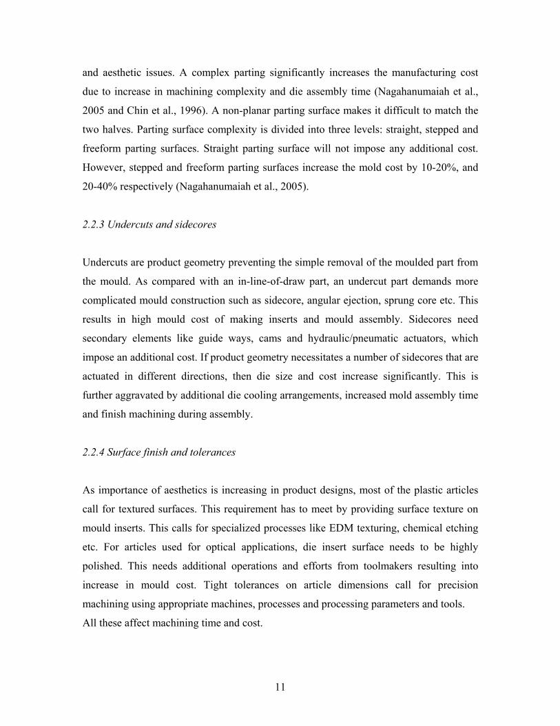
2.2.3 Undercuts and sidecores
Undercuts are product geometry preventing the simple removal of the moulded part from
the mould. As compared with an in-line-of-draw part, an undercut part demands more
complicated mould construction such as sidecore, angular ejection, sprung core etc. This
results in high mould cost of making inserts and mould assembly. Sidecores need
secondary elements like guide ways, cams and hydraulic/pneumatic actuators, which
impose an additional cost. If product geometry necessitates a number of sidecores that are
actuated in different directions, then die size and cost increase significantly. This is
further aggravated by additional die cooling arrangements, increased mold assembly time
and finish machining during assembly.
2.2.4 Surface finish and tolerances
As importance of aesthetics is increasing in product designs, most of the plastic articles
call for textured surfaces. This requirement has to meet by providing surface texture on
mould inserts. This calls for specialized processes like EDM texturing, chemical etching
etc. For articles used for optical applications, die insert surface needs to be highly
polished. This needs additional operations and efforts from toolmakers resulting into
increase in mould cost. Tight tolerances on article dimensions call for precision
machining using appropriate machines, processes and processing parameters and tools.
All these affect machining time and cost.
11

2.2.5 Die material
Most of the injection moulds and PDC dies are made up of hardened tool steels. In few
cases where production quantities are low and material doesn’t contains any abrasive
additives pre-hardened steel is used. Manufacturing process and parameters are directly
dependent on material manufacturability. In case of hardened steel heat-treatment
operation is essential. Hence die material influence mould machining lead time and cost.
2.2.6 Special accessories
To meet special requirements of articles, special accessories are required to be
incorporated in mould. To minimize material wastage in feeding system Hot runners
systems are widely used. For some articles the ejector mechanism needs to be
pneumatically actuated or on injection side. All these needs additional element of work in
moulds and PDC dies which affects the cost.
2.3 Cost Models for Injection Moulds and PDC Dies
Literature available on cost estimation for injection moulds and PDC dies broadly
classifies two basic approaches: Cost similarity and Cost functions. In cost similarity
approach cost of new mould is determined by comparing cost similar existing mould
already manufactured. This calls for proper storage and retrieval system of past data. This
approach is good for the tool room’s handling similar type of moulds. But generally this
is not the case in tooling industry. In Cost function approach dependency between the
cost of mould and its characteristics is expressed in mathematical function. The
characteristics are the independent variables or affecting quantities, which determine the
cost.
Combination of these two approaches is used by Menges et al. (1993) for estimating cost
of injection mould. Cost function approach is used for calculating core & cavity cost
while cost similarity approach is used for mould base and other std. elements cost. The
12

mould cost is divided into four groups namely, i) Cavity ii) Mould Base iii) Basic
functional components, and iv) Special functions.
i. Cavity: Core and cavity cost estimation is done by multiplying estimated machining
time by machine and labour hour rate.
Cc = (tc+ tE). CMW + CM
where,
Cc = Cost for cavity
tc = Time spent on cavity machining
tE = Time spent on EDM
CMW = Average machine and labour cost
CM = Additional material cost (inserts, electrodes etc.)
The time tc is calculated by using parameter as follows
tc = { CM . (CD+CA) CP
. CS+CC}. CT . CDD
. CN
where,
CM = Machining procedure
CD = Cavity depth
CA = Surface area of cavity
CP = Shape of parting line
CS = Surface quality
CC = Number of cores
CT = Tolerance
CDD = Degree of difficulty
CN = Number of cavities
The above-mentioned parameters and factors needs to established and calculated
further with respect to injection mould under estimation.
13

ii. Mould base: Cost of mould base is considered with grades pertaining to production
requirements. As it is available as a standard set in market cost of the mould base is
taken from supplier’s catalogue.
iii. Basic functional components: Basically injection mould consists of three functional
systems such as injection, cooling and ejection. Various costs associated with the
components of these functional systems are calculated separately. For injection
system cost of machining sprue, runners and gate is calculated. Cost of cooling
system depends on no. of holes to be drilled in plate. Cost of Ejection system is
derived from Ejector pin purchase cost and machining in Ejector and ejector back
plate.
iv. Special Functions: It includes costs of some special requirements like unscrewing
mechanism, three-plate mould accessories, slides etc.
Estimated cost of the above-mentioned cost groups are added to get estimated cost of the
injection mould.
Chin et al. (1996) developed an estimation approach, which uses knowledge based
decision tables, to estimate the cost of injection moulds. Typically decision tables provide
a means to handle “If-Then” situations to link the numerous decision factors in decision-
making process. A decision table based system (DTMOLD-1) was developed to
customise the mould cost estimation procedures and processes at the early product design
stage. The decision tables are built by using technical data, knowledge and mould making
rules in die making industry. For each decision table, the rules for the evaluation of a
specific target are included in the same decision table. The injection mould cost is broken
down into several categories according to the basic functional components of an injection
mould, namely, mould base material cost, mould insert material cost, cost of accessories
and processing cost. The first three cost elements are material costs while the processing
cost is basically the labour cost and process overheads. The processing cost is further
14

divided into: i) mould base, ii) mould insert and assembly, and iii) surface finish, and
polishing.
i) The mould base processing cost mainly includes the machining of the mould,
such as slot or pocket openings, ejecting system making, gate and runner
making, etc.
ii) The mould insert making and assembly cost are the costs incurred to make the
cavities and cores which usually require milling, EDM and heat-treatment
processes as well as the mould assembly.
iii) The costs of surface finish and polishing include the electro-plating of nickel,
chromium, etc., texture etching, and polishing processes.
Software called DTMOLD-1 is used to estimate mould cost, which is based on the
knowledge based decision tables. Figure 2.1 shows the flow diagram of the system
(DTMOLD-1) developed by Chin et al. (1996).
15

User Inputs
Determine no. of cavities
Determine mould base plates thickness
Determine standard mould base
Determine mould base material cost
Determine mould complexity code
Determine cost of accessories
Determine mould insert material cost
Determine mould base machining
cost
Determine surface finish
& heat treatment
cost
Determine assembly
cost
Determine mould inserts
machining cost
Calculate total mould cost
Figure 2.1: Flow chart (Chin et al., 1996)
Each cost element is estimated by using decision tables. Decision table for no. of cavities
is based on part size, presence of thread, number of undercuts, part tolerance
requirements and complexity of contour shape. Decision table for cost of mould base
includes factors like unscrewing moulds, slide-core moulds, split moulds and moulds
without undercut. Thickness of mould base is determined by depth of article from parting
line. For calculating processing cost of mould base, decision table based on injection
system, cooling system and ejector system is used.
16

Mould inserts processing and mould assembly cost is calculated by using decision table
to determine two-digit code for degree of complexity. First digit of this code is based on
decision tables, which considers attributes like complexity of the parting line (straight,
stepped or curved), the disposition of the cavity shape between mould halves and the
presence of undercut and types of undercut. The second digit takes into account mould
complexity due to the part size, the number of undercuts and the number of surface with
holes. The costs of accessories are estimated by using decision table, which includes part
size numbers and individual cost of these accessories.
Thus mould cost is estimated by software built on these decision tables. With limited
inputs from user related to article specification, the software calculates estimated cost of
injection mould.
While developing system for cost-effective design for injection moulded articles Chen
and Liu proposed feature-based cost estimation method for injection moulds (Chen et al.,
1999). The system is based on features of an article. The mould cost is linked with the
features of the article they are forming. An article size and shape complexity is
considered as main factors influencing cost of an injection mould. Shape complexity of
an article is determined by its feature structure and their interactions. Feature mapping is
done along with parting line, which determines the impact of feature shape and
interactions on mould insert cost. The surface finish requirement and tolerances on
features are also considered for estimating mould cost. Rather than exact calculation, this
approach is used for comparison and decision making at the design stage of an article.
An integrated framework for die and mould cost estimation is proposed by
Nagahanumaiah et al. (2005). This methodology is based on concept of cost drivers and
cost modifiers. Cost drivers depend on geometry and machining time. Cost modifiers
depend on complexity of the mould. In this approach all geometric features are mapped
to machining features, which are used as cost drivers and their cost is obtained by
17
analytical costing method. Other factors affecting the complexity of the mould are
considered as cost modifiers.
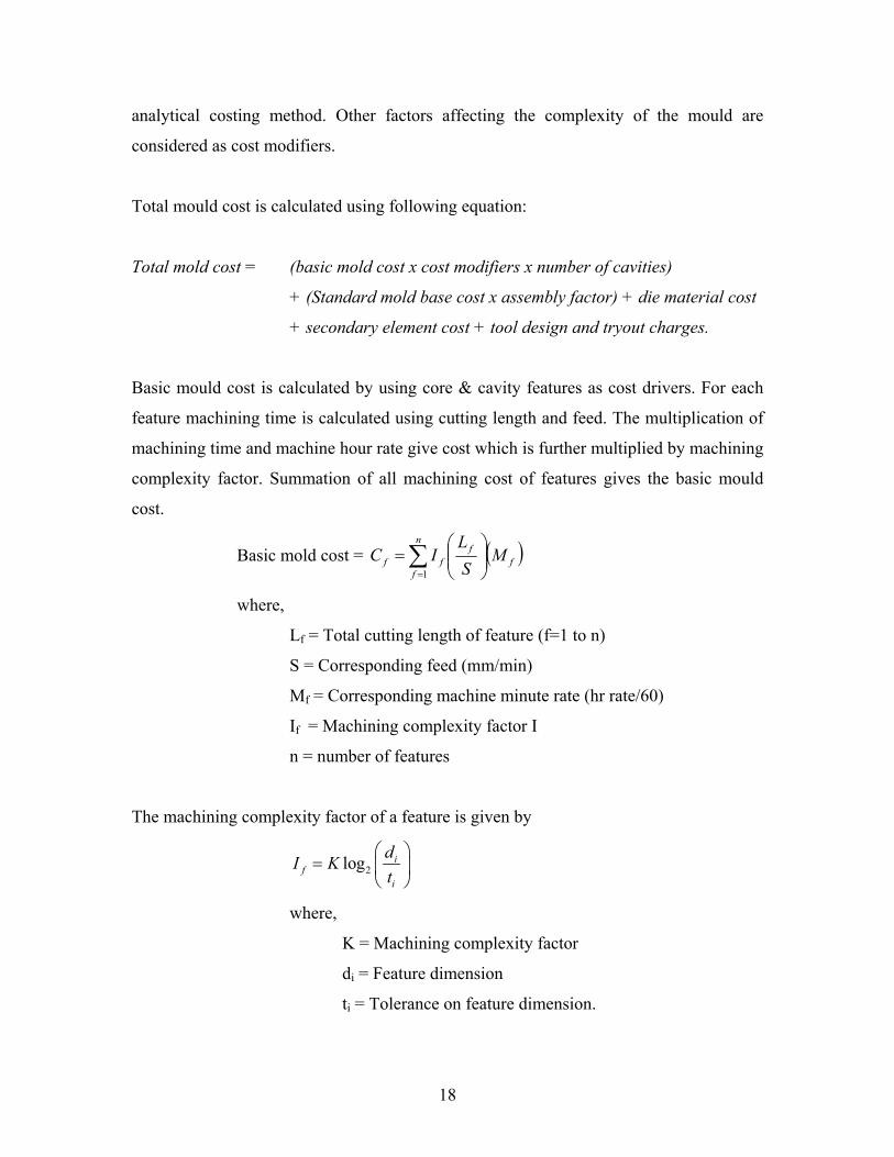
Total mould cost is calculated using following equation:
Total mold cost = (basic mold cost x cost modifiers x number of cavities)
+ (Standard mold base cost x assembly factor) + die material cost
+ secondary element cost + tool design and tryout charges.
Basic mould cost is calculated by using core & cavity features as cost drivers. For each
feature machining time is calculated using cutting length and feed. The multiplication of
machining time and machine hour rate give cost which is further multiplied by machining
complexity factor. Summation of all machining cost of features gives the basic mould
cost.
Basic mold cost = ( )ff
n
fff M
SL
IC ⎟⎟⎠
⎞⎜⎜⎝
⎛= ∑
=1
where,
Lf = Total cutting length of feature (f=1 to n)
S = Corresponding feed (mm/min)
Mf = Corresponding machine minute rate (hr rate/60)
If = Machining complexity factor I
n = number of features
The machining complexity factor of a feature is given by
2log if
i
dI Kt
⎛ ⎞= ⎜ ⎟
⎝ ⎠
where,
K = Machining complexity factor
di = Feature dimension
ti = Tolerance on feature dimension.
18

The cost modifiers are,
i) Die complexity factor: It includes parting surface complexity, presence of side
cores, surface finish/texture, ejector mechanism and die material.
ii) Parting surface complexity: Parting surface complexity is divided into three
categories namely straight, stepped and freeform.
iii) Core complexity: Presence of side cores and operating mechanisms
iv) Surface finish / texture: Polished or textured
v) Ejection mechanism: Ejector pins, cam operated or hydraulic-pneumatic
actuator.
vi) Die/ mould material: Hardened or pre-hardened.
Values of these cost modifiers are decided based on past experience. For individual tool
rooms these values can be established by using Quality Function Deployment (QFD)
approach.
2.4 Summary of Literature Survey
Cost estimation approaches available in literatures are useful in tool rooms involved in
developments of similar types of moulds having family of similar shapes.
The method based on use of knowledge-based decision tables (Chin et al., 1996)
need software to make use of these decision tables. This is difficult for small and
medium scale tool rooms. Also for tool rooms handling different types of tools
this approach will not give satisfactory results.
The feature based approach (Chen et al., 1999) use product CAD model for
calculating cost of core and cavity. The other elements of the mould cost are not
considered here in details. Moreover this approach is used to compare estimated
cost and to get cost-effective solution rather than exact estimation of cost of the
mould.
19

The cost estimation method proposed by Menges et al. (1993) is suitable for all
varieties of job but fail to address finer points of machining core & cavities.
Machining time estimation based on mean depth may mislead. The effect of
machining type (rough or finish), mould base machining, assembly time etc. are
not considered here. Being analytical in nature it involves calculations of many
parameters and hence doesn’t give quick estimation.
The integrated framework proposed by Nagahanumaiah et al. (2005) also
addresses variety of tools handled by tool rooms. The cost modifier values need to
be developed by using QFD technique. This approach needs very systematic
calculation of cost drivers and cost modifiers, which is difficult in small tool
rooms.
20
Chapter 3
Problem Definition
3.1 Motivation
Cost estimation of injection moulds and pressure die-casting dies is important for product
costing and decision making. Higher estimates may lead in loosing orders while lower
estimation will affect profitability. Hence accurate cost estimation needs to be done. At
present it is time consuming and needs expertise in mould making. Availability of such
expertise in tool rooms is becoming difficult. Hence need is felt to develop a method
which can give quick estimation and can be used by less experienced engineer having
basic knowledge of injection moulds and PDC design.
3.2 Objectives and Scope
The aim of this project is to develop cost model for injection mould and pressure die-
casting die which will fulfil following requirements:-
• Cost model should give estimated cost within 90% accuracy.
• Cost estimation should not be time consuming activity.
• Cost estimation can be done by less experienced engineer having basic knowledge
of injection mould and pressure die-casting die design.
• Cost estimation should be done by using common software like Microsoft Excel
or Access. It should not call for new software development.
The cost model will give cost estimation of design and manufacturing of injection moulds
and PDC. It doesn’t include costs incurred due to increase in set up time or WIP carrying
charges and overheads. The project aims at estimating cost of two-plate and three-plate
mould or die construction. It doesn’t include some special mould designs i.e. micro-
moulding or stack-moulding etc.
21

3.3 Approach
The cost estimation of injection moulds and pressure die-casting dies is done by dividing
the total cost into three major cost heads:
1) Basic mould cost
2) Mould base cost
3) Standard elements and accessories cost
1) Basic mould cost: It is the cost of manufacturing and assembly of mould inserts
i.e. core and cavity for injection mould or PDC. This cost is estimated by using
regression analysis for component geometric data and mould construction details.
The CAD model of an article along with mould or PDC design specification sheet
is used by estimator to derive the basic mould cost.
2) Mould base cost: Mould base cost is derived from mould base size. Mould base
size is decided by using knowledge-based decision tables. These decision tables
are developed to determine mould base and mould insert size.
3) Standard elements and accessories cost: Database is generated for costs of Std.
elements and accessories like hot nozzles, latches etc. The information from
accessories manufacturers catalogues is consolidated in common database.
Other cost elements like design cost and overheads are normally considered as percentage
of total mould cost, which is addition of above three major cost heads. Apart from this
mould insert raw material and Heat-treatment costs are derived from mould insert weight
calculated using decision tables.
22

Chapter 4
Mould Base Cost Estimation
Mould base consists of top plate, supports, guiding elements, punch holder, die holder
and ejector plates. Mould inserts forming an article are housed in punch and die holders.
These punch and die holders are located by using guide pillar and bush to maintain
correct location of punch insert and die insert during moulding. The size of the mould
base depends on size of article to be moulded, no. of cavities and presence of sidecore,
hot manifold if any.
Mostly these mould bases are available as standard sets from mould base manufacturers
like DME, HASCO, etc. The tool room under study for this cost model does not use these
standard mould bases. Mould bases are designed along with mould to suit article
requirements. However these mould bases are not manufactured in-house but are
purchased from vendors. These vendors manufacture the mould base as per design
supplied to them.
Therefore to estimate cost of mould base, it is essential to know the size of mould base.
To get this size of mould base decision tables are developed which use component details
for calculating size of mould base.
4.1 Decision Tables
Knowledge-based systems are used in many fields for making decisions or in the support
of decision-making. Basically it has got knowledge about that field of expertise i.e.
procedures, strategies, rules of thumb for problem solving etc. This knowledge is derived
from human experts in the field and then encoded by some tools. A decision table is one
of such tool used to gather such knowledge for making decisions or to support decision-
making (Chin et al., 1996).
23

A decision table is a symbolic way of representing the logical interdependence between
events. It provides a means to handle “If-Then” situations to link the numerous decision
factors in the decision making process. As decision tables present decision alternatives in
a simple tabular form, they are clearly displayed and readily understood by the reader
even for complex decision-making situations. Basically these decision tables have
condition stub and action stub. Condition stub contains all the conditions that must be
considered before selecting a course of action. Action stub contains the entire set of
individual actions governed by the decision table.
The objective of this project is to develop cost model for injection mould and pressure
die-casting dies which gives cost estimation quickly by less experience engineer having
basic knowledge of mould and die designing. Typically experience person having
knowledge of design and manufacturing aspects of mould and die making does the cost
estimation. From component geometry, that person is in position to understand concept of
mould design and difficulties in manufacturing these moulds. It will be difficult to
anticipate these things for person having less experience. Hence there is need to develop
some mechanism which will support less experience person to decide mould design
aspects. The decision tables are considered here as a mechanism to fulfil this need.
4.2 Development of Decision Tables
The decision tables developed here are used to derive size of mould insert and mould
base. Once these sizes are derived, cost of mould insert material and cost of mould base
can be estimated. The rule of thumbs and practices followed in designing mould inserts
and mould base are considered here while formulating these decision tables. The mould
insert sizes are then verified to satisfy maximum bearing stress criterion.
The estimator will have component drawing or model for which an injection mould or
pressure die-casting die is to be made. Using basic knowledge of die designing estimator
will be in position to decide parting line for component. Length, width, depth in punch
side and depth in core side will be derived from this. If the component has undercuts in
24

parting directions then sidecores are required. Number of side cores and respective travel
can be determined from component drawing or model. The gating position will be
decided considering functional and aesthetic requirement of component. Product designer
will validate this position. The filling pattern will be judged and taken into account for
gate position. Gating position can be at centre of the component or on side face. Number
of cavities is decided by customer taking into account annual requirement of the
component. Majority of cases it is singe cavity or two cavities. All these will be input to
the cost estimator to use decision table to decide mould insert size and mould base size.
The inputs mentioned above are used in condition stub in decision tables. From length,
width and thickness in punch and die, the mould insert sizes will be derived. The mould
insert thickness is derived from depth of component in punch side and die side. Mould
insert sizes are then used to determined mould base length and width. The punch holder
and die holder thickness are derived from respective mould insert thickness. Ejection
stroke is derived from component thickness in punch side. This will be used to decide
spacer thickness on moving side. Using all this thickness details the mould base height or
shut height is derived.
4.3 Decision Tables for Mould Layout
The figure mentioned below gives details of nomenclature used as inputs available to cost
estimator for using decision tables.
Figure 4.1: Component nomenclature
25
Where,
L= Component length
W= Component width
H= Component thickness
Hp= Component thickness on punch side
Hd= Component thickness on die side
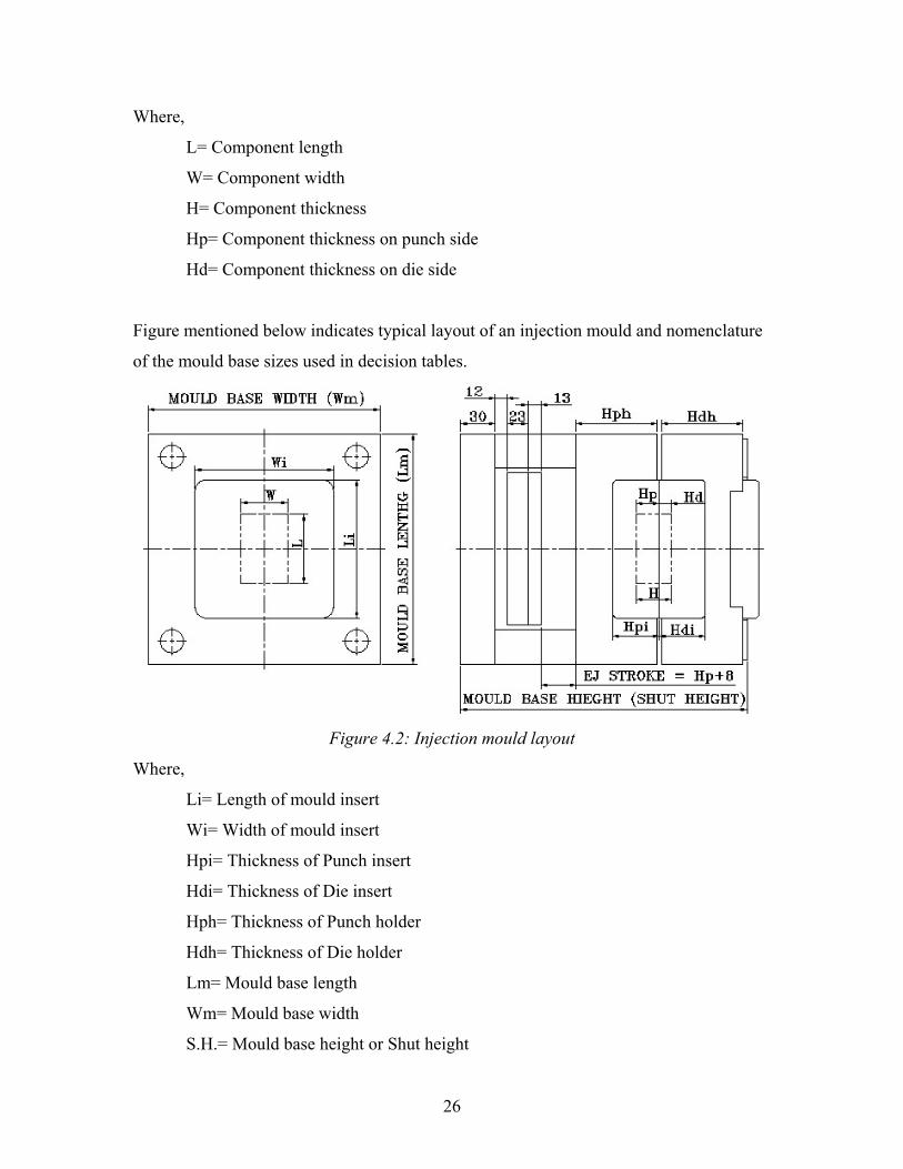
Figure mentioned below indicates typical layout of an injection mould and nomenclature
of the mould base sizes used in decision tables.
Figure 4.2: Injection mould layout
Where,
Li= Length of mould insert
Wi= Width of mould insert
Hpi= Thickness of Punch insert
Hdi= Thickness of Die insert
Hph= Thickness of Punch holder
Hdh= Thickness of Die holder
Lm= Mould base length
Wm= Mould base width
S.H.= Mould base height or Shut height
26

Table 4.1: Decision table for single cavity mould having gate at centre
Component Length (L)
Component Width (W)
Insert Length
(Li)
Insert Width (Wi)
Punch Insert Thickness
(Hpi)
Die Insert Thickness
(Hdi)
Mould base
Length (Lm)
Mould base Width (Wm)
Suitable machine
< 90 < 50
If (L x W) < 4500
L + 2 { Max (25 or 0.6Hp
or 0.6Hd)}
W + 2 { Max (25 or 0.6Hp
or 0.6Hd)}
Hp+30 Hd+25
Li + 2 { Max (50 or Hpi or Hdi)}
Wi + 2 { Max (50 or Hpi or Hdi)}
30 T
< 120 < 100
If (L x W) < 12000
L + 2 { Max (30 or 0.6Hp
or 0.6Hd)}
W + 2 { Max (30 or 0.6Hp
or 0.6Hd)}
Hp+30 Hd+25
Li + 2 { Max (50 or Hpi or Hdi)}
Wi + 2 { Max (50 or Hpi or Hdi)}
80 T
< 180 < 120
If (L x W) < 22500
L + 2 { Max (35 or 0.6Hp
or 0.6Hd)}
W + 2 { Max (35 or 0.6Hp
or 0.6Hd)}
Hp+30 Hd+25
Li + 2 { Max (60 or Hpi or Hdi)}
Wi + 2 { Max (60 or Hpi or Hdi)}
150 T
< 250 < 180
If (L x W) < 45000
L + 2 { Max (40 or 0.6Hp
or 0.6Hd)}
W + 2 { Max (40 or 0.6Hp
or 0.6Hd)}
Hp+30 Hd+25
Li + 2 { Max (60 or Hpi or Hdi)}
Wi + 2 { Max (60 or Hpi or Hdi)}
300 T
27

Table 4.2: Decision table for single or two-cavity mould having gate on side face
Component Length (L)
Component Width (W)
Insert Length
(Li)
Insert Width (Wi)
Punch Insert Thickness
(Hpi)
Die Insert Thickness
(Hdi)
Mould base
Length (Lm)
Mould base Width (Wm)
Suitable machine
30 T if LxW=4500 for Sigle Cavity
< 90 < 50
L + 2 { Max (25 or 0.6Hp or 0.6Hd)}
2 {W+30+ Max (25 or 0.6Hp or 0.6Hd)}
Hp+30 Hd+25
Li + 2 { Max (50 or Hpi or Hdi)}
Wi + 2 { Max (50 or Hpi or Hdi)} 30 T if
LxW=2250 for Two Cavity
80 T if LxW=12000
for Sigle Cavity
< 120 < 100
L + 2 { Max (30 or 0.6Hp
or 0.6Hd)}
2 {W+30+ Max (30 or 0.6Hp
or 0.6Hd)}
Hp+30 Hd+25
Li + 2 { Max (50 or Hpi or Hdi)}
Wi + 2 { Max (50 or Hpi or Hdi)} 80 T if
LxW=6000 for Two Cavity
150 T if LxW=22500
for Sigle Cavity
< 180 < 120
L + 2 { Max (35 or 0.6Hp
or 0.6Hd)}
2 {W+30+ Max (35 or 0.6Hp
or 0.6Hd)}
Hp+30 Hd+25
Li + 2 { Max (60 or Hpi or Hdi)}
Wi + 2 { Max (60 or Hpi or Hdi)} 150 T if
LxW=11250 for Two Cavity
300 T if LxW=45000
for Sigle Cavity
< 250 < 180
L + 2 { Max (40 or 0.6Hp
or 0.6Hd)}
2 {W+30+ Max (40 or 0.6Hp
or 0.6Hd)}
Hp+30 Hd+25
Li + 2 { Max (60 or Hpi or Hdi)}
Wi + 2 { Max (60 or Hpi or Hdi)} 300 T if
LxW=22500 for Two Cavity
28

Table 4.3: Decision table to derive mould base thickness
Component Length (L)
Component Width (W)
Die Holder Thickness
(Hdh)
Punch Holder Thickness
(Hph)
Parallel Thickness
(Hs)
Base Plate Thickness
(Hb)
Mould Base Hieght / Shut Height
< 90 < 50 Hdi+25 Hpi + 40 Hp + 56 30 Hdh + Hph + Hs + 35
< 120 < 100 Hdi+25 Hpi + 40 Hp + 56 30 Hdh + Hph + Hs + 35
< 180 < 120 Hdi+30 Hpi + 50 Hp + 56 30 Hdh + Hph + Hs + 35
< 250 < 180 Hdi+30 Hpi + 50 Hp + 56 30 Hdh + Hph + Hs + 35
4.4 Moulds with Sidecore and Hot manifold
When an article has undercut which needs sidecore mechanism to form the same, the
length and width of mould base increases. This is due to space required to accommodate
slide, angle pin or dogleg cam, and wedge for locking during moudling. Following figure
indicates nomenclature of component needing sidecore mechanism.
Figure 4.3: Component with undercut
Where,
St = Undercut length
29

For the component having undercut on surface along with width W, the mould base
length will be
Lm = Li + 2 (St + 90)
While for component having undercut on surface along with length L, the mould base
width will be
Wm = Wi + 2 (St + 90)
The other values of mould base sizes will be as per decision tables (Table 4.1, 4.2, and
4.3).
When quantity of component produced is higher, the wastage of plastic raw material in
runner and gating systems is substantial. Hence mould is designed to avoid this wastage
by using Hot manifolds in case of multi-cavity mould and Hot Nozzle system for single
cavity mould. To accommodate this Hot manifold plates are added in mould base
between Die holder and Fixed platen of the machine. The typical thicknesses of these
plates are 90mm and 38 mm for Manifold plate and Top plate simultaneously. Hence
when mould is designed for Hot manifolds Mould base height size will increase by 128
mm and when only nozzle is used mould base height will increase by 38 mm. Estimator
need to take into account this while considering mould base size.
4.5 Cost of Mould Base
Cost of mould base is sum of cost of raw material and machining of its elements. The raw
material for plates is C45 steel whereas guiding elements are of High Carbon High
Chromium (HcHcr) steel with hardness up to 58-60 HRC. The machining operation for
these plates includes drilling, boring, milling and grinding. These plates are then
assembled together using guiding elements and screws. As all mould bases have
similarity in construction, manufacturing of these mould bases follows similar machining
operations. The factor, which matters to the change in cost, is size of mould base.
Therefore analysis is done to find correlation between mould base size and its cost. Past
data is collected for purchase of the mould bases of different sizes. Table 4.4 shows data
collected for analysis.
30

Table 4.4: Mould base sizes and costs
SR. NO. TOOL NO. PR VALUE
(in Rs.) PR DATE
NO. OF MONTHS
W.R.T. ANALYSIS
DATE
CORRECTED PR VALUE
(in Rs.) LENGTH (in mm)
WIDTH (in mm)
SHUT HEIGHT (in mm)
MOULD BASE
VOLUME (in cc)
1 DCS53107/1P2 327000 07-Feb-05 23.0 399518 446 446 459 91302.44
2 DCM57853/1P1 64000 12-May-04 32.1 84583 220 280 252 15523.2
3 DCM57854/1P1 61000 29-Apr-04 32.5 80923 296 296 281 24620.09
4 DSS53067/1P2 230000 28-Dec-04 24.4 284366 327 450 510 75046.5
5 DSS53000/1A6 82000 14-Sep-06 3.6 84583 430 300 312 40248
6 DSS50005/1A2 273000 29-Dec-04 24.4 337433 340 500 308 52360
7 DCS53678/1P1 100000 15-Jun-05 18.8 117727 260 365 281 26666.9
8 DCS53676/1P1 109000 15-Jun-06 6.6 115439 300 350 320 33600
9 DSS50006/1A3 249000 14-Mar-05 21.9 301150 325 450 520 76050
10 DCM57856/1P1 109000 17-Oct-05 14.6 123792 280 350 370 36260
11 DCS53697/1P1 370000 17-Oct-05 14.6 420210 450 520 520 121680
12 DCS53719/1P1 436000 11-Dec-05 12.8 487335 455 455 525 108688.13
13 DCS53933/1P1 96000 20-Oct-05 14.5 108933 300 315 390 36855
14 DCS53932/1P1 95000 20-Jun-05 18.6 111678 300 300 275 24750
15 DCM57894/1P1 56000 11-Dec-05 12.8 62594 260 296 215 16546.4
16 DCS53927/1P1 110000 20-Oct-05 14.5 124819 300 420 371 46746
17 DSS53010/1A2 164000 09-Jan-06 11.8 181775 400 500 363 72600
18 DSS53027/1P3 104000 02-Aug-06 5.0 108622 380 300 319 36366
19 DCS53069/1P1 132000 11-Dec-06 0.6 132729 380 300 305 34770
20 DCM56028/1P1 160000 20-Dec-06 0.3 160464 330 270 267 23789.7
21 DSS50285/1A1 170000 09-Oct-05 14.9 193518 270 296 293 23416.56
22 DSS50284/1A1 175000 09-Oct-05 14.9 199210 270 296 293 23416.56
23 DCL50914/1P2 270000 09-Dec-06 0.7 271649 450 500 484 108900
31

4.6 Regression Analysis
Data regarding mould base sizes and its purchase cost is collected. As these purchases are
done from last three years, for analysis purpose the purchase cost is converted to current
purchase value considering 11% inflation rate per annum. From mould base size mould
base volume is calculated. Regression analysis is done to find correlation between
modified purchase cost and volume of mould base.
Figure 4.4: Regression plot for Corrected PR value and Mould Base volume
32

Figure 4.5: Residual plot
From regression analysis, linear relationship is found between mould base volume and its
cost. To check this linear model, the residual plot is drawn. From residual plot it is
observed that the residuals are spread above and below of the fitted line and hence linear
model for this regression analysis holds good (Chatterjee et al., 1991)
4.7 Result
From regression analysis following equation is derived for cost of mould base: -
Estimated cost of mould base (in Rs.) = 34187 + (3.22 X Mould base volume in cc)
….. (4.1)
33

Chapter 5
Basic Mould Cost Estimation
5.1 Basic Mould Cost
Basic mould cost is cost of core and cavity inserts. Core and cavity inserts are replica of
an article. These may be single block or multiple inserts housed together in core or cavity
housings, which are part of mould base. In general 50-60% of mould cost is cost of this
core and cavity inserts. This cost comprises of material cost and manufacturing cost.
Manufacturing cost consists of machining cost and fitting or assembly cost.
Material cost of core and cavity insert can be estimated by using decision tables
mentioned in chapter four. From the article data the mould insert length, width and
thickness can be derived. From this volume and weight of mould inserts can be
calculated. As cost estimator knows rate of mould insert material; raw material cost of
mould inserts can be estimated.
The manufacturing cost of mould inserts depends on size and complexity of these inserts.
Manufacturing of mould inserts includes following operations in general depending on
mould insert profile (Menges, et al., 1993): -
Shaping and milling
Drilling and tapping
Jig boring
NC path generation and CNC milling
Heat treatment
EDM- Spark erosion
EDM- Wire erosion
Grinding
Polishing
Surface treatments like coating or texturing.
34

5.2 Difficulties in Basic Mould Cost Estimation
At the time of mould cost estimation, detail mould design is not made and hence the
exact size and shape of mould insert is not known. The time available for cost estimation
and the low order to estimate ratio doesn’t allow detailed mould insert design for
estimating cost. In absence of design of mould inserts, the cost estimation becomes
challenging task.
The manufacturing processes for mould inserts are dependent on profile of mould insert,
which is replica of an article. As tool rooms are involved in handling variety of jobs,
where there is very less similarity between two jobs; the previous cost data also doesn’t
help much in estimating manufacturing cost. Along with this, facility available in tool
room also plays important role in deciding the process sequence or manufacturing
strategy for mould inserts. As tool room has to handle variety of jobs there is difficulty in
standardizing this sequence. All these factors create difficulties in estimating cost of
mould insets.
5.3 Cost Estimation Approach
The mould inserts is replica of an article for which mould is designed. Though there is
less similarity between mould inserts and there is variation in sequence of machining
operations, the amount of material to be removed from mould insert is equal to volume of
article. Therefore there should be some correlation between manufacturing cost and
volume of an article. Along with this the surface area of an article is same as surface area
of mould inserts excluding cut bearing faces where there is metal-to-metal contact of
mould inserts in two halves. Therefore it is decided to check the correlation between
mould insert machining cost and article volume, surface area.
It is also observed that for the same volume or same surface area manufacturing cost is
related with complexity of an article. For same volume of material removal, mould
inserts having simple geometries can be manufactured by only milling operation but for
complex profile machining, along with milling operation spark erosion has to be
performed on mould inserts. This changes manufacturing cost of mould insert to great
35

extend due to low material removal rate of EDM operations. Hence there is need to check
correlation between complexity of article and mould inserts manufacturing cost.
The mould insert are to be fitted into fixed half and moving half of mould base and has to
insure perfect contact with each other along parting line to ensure flash-free article during
moulding. The matching of these inserts depends on parting line profile. The time and
accuracy of machining required is high for complex parting line than straight parting line.
Along with this if article has an undercut that needs sidecore, extra elements for sidecore
mechanism has to be provided in mould, which increase cost of mould insert
manufacturing and time taken to assemble these sidecores. In case of multi-cavity mould
there is advantage of repeating same manufacturing process for all cavity inserts. Though
machining operation time remains same, the CNC programming time and setting time
reduces drastically. Therefore cost of mould inserts for multi-cavity mould is definitely
lesser than single cavity mould insert of same component. Therefore effect of parting
line, sidecore and multi-cavity mould construction are to be taken into account while
estimating mould insert cost.
5.4 Regression analysis Regression analysis is carried out to find correlation between basic mould cost i.e. cost of
manufacturing of mould insert and different parameters like volume, surface area,
complexity factor, parting line type, no. of sidecores, no. of cavities etc. as discussed in
previous section. For this cost data of the injection moulds and pressure die-casting dies
manufactured in recent past is collected. Required geometric data of an article; which is
formed by these moulds is gathered. Mould construction is checked to find out parting
line type, no. of cavities. Table 5.1 on next page gives data collected regarding details of
component data and mould data. This data collected includes small component of size
36.5 x 10 x 2.5 mm having volume 314 mm3 to a large component of size 554 x 554 x 59
mm having volume 910614 mm3. Being confidential, this table indicates data for only
three moulds. Refer Appendix for details of all the elements. This also indicates 3D view
of these components along with overall sizes, volume, Surface area, and Nominal
thickness.
36
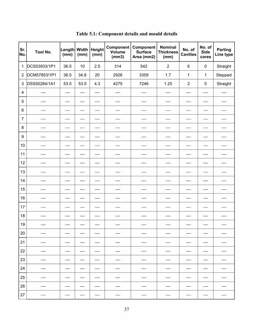
Table 5.1: Component details and mould details
Sr. No. Tool No. Length
(mm) Width (mm)
Height (mm)
Component Volume (mm3)
Component Surface
Area (mm2)
Nominal Thickness
(mm) No. of
Cavities No. of Side
coresParting
Line type
1 DCS53933/1P1 36.5 10 2.5 314 542 2 6 0 Straight
2 DCM57853/1P1 36.5 34.8 20 2928 3359 1.7 1 1 Stepped
3 DSS50284/1A1 53.5 53.5 4.3 4275 7246 1.25 2 0 Straight
4 __ __ __ __ __ __ __ __ __ __
5 __ __ __ __ __ __ __ __ __ __
6 __ __ __ __ __ __ __ __ __ __
7 __ __ __ __ __ __ __ __ __ __
8 __ __ __ __ __ __ __ __ __ __
9 __ __ __ __ __ __ __ __ __ __
10 __ __ __ __ __ __ __ __ __ __
11 __ __ __ __ __ __ __ __ __ __
12 __ __ __ __ __ __ __ __ __ __
13 __ __ __ __ __ __ __ __ __ __
14 __ __ __ __ __ __ __ __ __ __
15 __ __ __ __ __ __ __ __ __ __
16 __ __ __ __ __ __ __ __ __ __
17 __ __ __ __ __ __ __ __ __ __
18 __ __ __ __ __ __ __ __ __ __
19 __ __ __ __ __ __ __ __ __ __
20 __ __ __ __ __ __ __ __ __ __
21 __ __ __ __ __ __ __ __ __ __
22 __ __ __ __ __ __ __ __ __ __
23 __ __ __ __ __ __ __ __ __ __
24 __ __ __ __ __ __ __ __ __ __
25 __ __ __ __ __ __ __ __ __ __
26 __ __ __ __ __ __ __ __ __ __
27 __ __ __ __ __ __ __ __ __ __
37

For the injection moulds and PDC mentioned in Table 5.1 cost data is collected. This cost
data was available with respect to operations performed on mould insert. The cost data is
then divided into following cost heads: -
1) Design cost
2) Pre-machining cost
3) CNC milling cost
4) Heat-treatment cost
5) EDM cost
6) Grinding cost
7) Fitting and Assembly cost
8) Vendor out machining cost
9) Mould base and Std. Element purchase cost
10) Overheads
The manufacturing cost of mould insert is calculated by following equation: -
Mould insert mfg. Cost = Pre-machining cost + CNC milling cost + EDM cost +
Grinding cost + Vendor out machining cost + Fitting and Assembly cost
.... (5.1)
The cost incurred for Heat-treatment of mould insert is excluded from this as it can be
calculated by using size of mould insert derived form decision tables and per kg rate of
Heat-treatment operation. Due to in-house capacity limitations, small mould insert are
machined at vendors. This cost incurred is included in Vendor out machining cost.
As we are interested in analyzing manufacturing cost of mould insert with respect to
component volume, surface area etc. the mould insert manufacturing cost per cavity is
derived using no. of cavities in the mould. The injection moulds and PDC dies used here
for analysis are manufactured in last two years and hence mould insert cost per cavity is
corrected to current mould insert manufacturing cost considering 11 % inflation rate per
annum. Table 5.2 gives all these cost elements discussed above for the moulds & dies
mentioned in Table 5.1 in same sequence. The details of only three moulds are mentioned
in this table. Refer Appendix for cost details of all moulds. All cost mentioned in this
table are in Rs.
38

Table 5.2: Mould insert manufacturing cost data.(in Rs.)
Sr. no.
Pre-machining
cost
CNC milling
cost EDM cost
Grinding cost
Vendor out
machining cost
Fitting & Assembly
cost
Total Mould Insert mfg. cost
No. of Cavities
Mould Insert mfg. Cost per
cavity
Date of mfg.
Corrected M.I.mfg. cost per cavity
1 __ __ __ __ __ __ __ __ __ __ __
2 __ __ __ __ __ __ __ __ __ __ __
3 __ __ __ __ __ __ __ __ __ __ __
4 34157 144071 57383 41726 10260 54501 342098 1 342098 31-Dec-05 391461
5 90129 163229 174977 90732 16019 201347 736433 6 122739 30-Jun-06 133271
6 23075 0 14000 16680 61535 35045 150335 2 75168 28-Feb-06 84555
7 __ __ __ __ __ __ __ __ __ __ __
8 __ __ __ __ __ __ __ __ __ __ __
9 __ __ __ __ __ __ __ __ __ __ __
10 __ __ __ __ __ __ __ __ __ __ __
11 __ __ __ __ __ __ __ __ __ __ __
12 __ __ __ __ __ __ __ __ __ __ __
13 __ __ __ __ __ __ __ __ __ __ __
14 __ __ __ __ __ __ __ __ __ __ __
15 __ __ __ __ __ __ __ __ __ __ __
16 __ __ __ __ __ __ __ __ __ __ __
17 __ __ __ __ __ __ __ __ __ __ __
18 __ __ __ __ __ __ __ __ __ __ __
19 __ __ __ __ __ __ __ __ __ __ __
20 __ __ __ __ __ __ __ __ __ __ __
21 __ __ __ __ __ __ __ __ __ __ __
22 __ __ __ __ __ __ __ __ __ __ __
23 __ __ __ __ __ __ __ __ __ __ __
24 __ __ __ __ __ __ __ __ __ __ __
25 __ __ __ __ __ __ __ __ __ __ __
26 __ __ __ __ __ __ __ __ __ __ __
27 __ __ __ __ __ __ __ __ __ __ __
39

From Table 5.2 we get cost of mould insert manufacturing for respective component. The
component volume is also mentioned in Table 5.1. Therefore we can find out cost of
mould insert manufacturing per volume for each component. This cost of mould insert
manufacturing per volume is used to perform regression analysis. The cost per volume
will change as part become more and more complex. Following factors are considered as
characteristics of component and mould, which will affect cost of mould insert
manufacturing per volume: -
Volume of Bounding Box 1) Volume Ratio = ---------------------------------------
Volume of component
Surface area of component 2) Area Ratio = ----------------------------------------------------
Surface area of cube having equivalent component volume
(Surface area of component)1/2
3) (S.A.)1/2 / (Vol.)1/3 = --------------------------------------- (Volume of component)1/3
4) No. of additional cavities = Total no. of cavities in mould - 1
5) Parting line factor: From literature on mould cost, it is found that straight parting
surface will not impose any additional cost. However, stepped and freeform
parting surfaces increase the mould cost by 10-20%, and 20-40% respectively
(Nagahanumaiah et al., 2005). In statistical tools to indicate relationship between
two parameters factors 1, 3 & 9 are used to indicate low, medium, and strong
relationship respectively. Similarly factors 1, 3 & 9 are used here for straight,
stepped and complex parting line.
6) Nominal thickness of component
Table 5.3 shows the data of all the above-mentioned factors used for regression analysis.
This table indicates values for three moulds. Refer Appendix for details of all the
elements.
40

Table 5.3: Data for regression analysis
Sr. no. Tool no.
No. of additional cavities
Parting line
factor Nominal
Thickness(Volume Ratio)1/3
(Area Ratio)2
(S.A.)1/2 / (Volume)1/3
Corrected M.I. Mfg. cost per cavity (Rs.)
Cost per Volume
(Rs/mm3)
1 __ __ __ __ __ __ __ __ __
2 __ __ __ __ __ __ __ __ __
3 __ __ __ __ __ __ __ __ __
4 __ __ __ __ __ __ __ __ __
5 __ __ __ __ __ __ __ __ __
6 __ __ __ __ __ __ __ __ __
7 DCS53914/1P1 1 3 2.0 1.8036 14.3684 4.7690 298000 43.5800
8 DCS53677/1P1 1 9 1.5 2.0550 23.7785 5.4091 296042 42.1472
9 DSS53027/1P3 3 3 1.5 2.2949 14.0991 4.7465 349904 46.1859
10 __ __ __ __ __ __ __ __ __
11 __ __ __ __ __ __ __ __ __
12 __ __ __ __ __ __ __ __ __
13 __ __ __ __ __ __ __ __ __
14 __ __ __ __ __ __ __ __ __
15 __ __ __ __ __ __ __ __ __
16 __ __ __ __ __ __ __ __ __
17 __ __ __ __ __ __ __ __ __
18 __ __ __ __ __ __ __ __ __
19 __ __ __ __ __ __ __ __ __
20 __ __ __ __ __ __ __ __ __
21 __ __ __ __ __ __ __ __ __
22 __ __ __ __ __ __ __ __ __
23 __ __ __ __ __ __ __ __ __
24 __ __ __ __ __ __ __ __ __
25 __ __ __ __ __ __ __ __ __
26 __ __ __ __ __ __ __ __ __
27 __ __ __ __ __ __ __ __ __
41

5.5 Equation for Basic Mould Cost Estimation
Regression analysis is performed on the cost data mentioned in Table 5.3. It is observed
that correlation coefficient, R-sq is 73.9% which is ok, but observation no. 20 has large
residual. Hence it has been removed form data set and regression anlysis is performed
again. From this analysis we get following equation for cost of mould insert
manufacturing per volume.
Cost per Volume (Rs/mm3) = C0 + C1 (Volume Ratio)1/3 + C2 (Area Ratio)2
- C3 { (S.A.)1/2 / (Volume)1/3 } + C4 Parting line factor
- C5 No. of additional cavities – C6 Nominal Thickness.
…. (5.2)
Being confidential, the values of factors C0 to C6 are mentioned in Appendix. The
correlation coefficient, R-sq value for above equation is 82.1%, which indicates validity
of above equation. Along with this, the graph plotted for residual versus order of data
also indicates that observations doesn’t show any specific trend and residuals are
randomly distributed about origin.
Figure 5.1: Residual plot versus order of data
42
From the above-mentioned equation it is observed that cost of mould insert
manufacturing increases as component becomes more and more complex. As complexity
increases, volume ratio and area ratio increases and hence cost per volume will increase.
The effect of surface area to volume ratio of component has to be considered with area
ratio and volume ratio. As parting line becomes more and more complex the cost of
mould insert manufacturing will increase. The effect of side core needs to be considered
while deciding parting line factor. Increase in no. of additional cavity will reduce cost of
manufacturing of mould insert as it gets advantage of repeating same operations. In case
of multi-cavity mould, the efforts on CNC programming, set up etc. gets divided over
number of cavities. Regression equation shown here clearly indicates this fact. It can be
also observed that there is reduction in cost per volume as nominal thickness of
component increases. This is because as nominal thickness increases, the insert splitting
and machining becomes simpler.
5.6 Result
The basic mould cost or cost of mould insert manufacturing is calculated by using cost
per volume as follows:
Basic mould cost (Rs.) = Cost per Volume (Rs./ mm3) x Volume of component
x No. of cavities ….(5.3)
Where cost per volume is calculated by using equation (5.2).
43

Chapter 6
Other Cost Elements
Mould base cost and cost of mould inserts are major elements in cost of injection mould
and pressure die-casting dies. Apart from these two elements mould cost includes its
design cost, heat-treatment cost, surface treatment cost, raw material cost of mould
inserts, standard elements purchase cost and overheads. This chapter elaborates cost
estimation of these cost elements.
6.1 Mould Insert Material and Treatment Cost
Mould inserts are normally of HCHCR steel having hardness up to 52-54 HRC. From
decision tables mentioned in Chapter Four the size of mould insert can be derived. This
will give volume of mould inserts and hence weight. By knowing per Kg rate of raw
material the mould insert material cost can be estimated. Similarly by knowing per kg
rate of Heat-treatment operation estimator can find out cost of Heat-treatment. The
following equation will give cost of raw material and Heat-treatment.
Mould insert material and Heat-treatment cost = (per kg rate of material + per kg rate of
Heat-treatment operation) X
{[(Li x Wi) (Hpi + Hdi)] x 7.85 x 10⁻⁶} …. (6.1)
Where,
Li= Length of mould insert in mm.
Wi= Width of mould insert in mm.
Hpi= Thickness of Punch insert in mm.
Hdi= Thickness of Die insert in mm.
As mentioned above the values of Li, Wi, Hpi and Hdi will be derived from component
size and mould construction using decision table. Cost estimator need to have an update
on cost of raw material for mould inserts and heat-treatment cost.
44
Most of the time plastic components have aesthetic requirements like matt finish or
mirror finish on external face of component. This call for surface treatment of mould
inserts forming these external surfaces of component. Cost of these surface treatment is
considered in this regards is basically cost of providing matt finish by EDM or chemical
etching, polishing, coating etc. This cost can be estimated by knowing cost of surface
treatment and surface area of component needing this treatment. Following equation
gives this estimated cost:
Surface treatment cost = Surface area of component having aesthetic requirement
x Rate of corresponding surface treatment.
…. (6.2)
6.2 Design Cost Estimation
Design cost of injection mould and PDC is proportional to total cost of the same.
Typically it is estimated as certain percentage of total mould cost depending on design
deliverables. Though this percentages changes with respect to no. of cavities, no. of
sidecores, complexity etc., same will change total cost of mould. For tool room under
study for development of cost model, it is observed form past data of moulds and PDC
that design cost is 20% of total mould cost excluding overheads. Therefore in the cost
model developed design cost is calculated by using following equation:
Design cost = 0.2 x (Mould Base cost + Mould insert raw material & treatment cost +
cost of standard elements + Basic mould cost)
…. (6.3)
6.3 Standard Element Cost Data
In injection moulds and pressure die-casting dies many times accessories are used which
are available in market as Standard elements. Hot Nozzles and Hot manifolds are used to
avoid material wastage in feeding system. Some accessories are used in ejection system
to ensure that ejector pins are retracted back before mould is closed. The standard spring-
loaded latches ensures sequential opening of the mould. Standard locators are used to
maintain precise alignment of core and cavity side. All these accessories need not have to
be manufactured in tool room. These accessories are purchased as standard elements
45

from suppliers. Hence to take care of the cost of the standard element, purchase cost data
of these standard elements is collected. At the time of estimating mould cost, estimator
need to take into account requirement of standard elements and then refer the purchase
data for cost of standard element.
6.4 Overhead Cost
Apart from direct material and direct labour cost, indirect cost in terms of overheads is
associated for manufacturing any sort of product. This overhead includes most of the
Fixed cost elements like plant and machineries, salaries of staff and other common
services used by manufacturing shops. Typically, overheads are assumed as certain
percentage of direct material and direct labour cost. For tool room under study for this
cost model, the overheads include the common services like hardware’s, stores, purchase
section, staff salaries, plant maintenance etc. The overhead percentage will change for
other tool rooms depending upon consideration of common services under overheads.
46
Chapter 7
Cost Model
We have seen estimation of different cost elements of injection moulds and pressure die-
casting dies. In this chapter all these elements are consolidated to get total cost injection
mould or pressure die-casting die.
7.1 Structure of Cost Model
Total cost of injection mould or pressure die-casting die is divided into following five
elements:
1) Mould Base cost: This is derived from volume of mould base. To calculate mould
base volume mould base size is derived. By using decision table, size of mould
base is calculated from component size and mould construction type. Equation
(4.1) gives this cost element.
2) Basic Mould cost: This is cost of manufacturing and assembly of mould inserts.
This cost is derived from regression equation which uses geometric details of
component like volume, surface area etc. and mould construction parameters like
no. of cavities, parting line type etc. Equation (5.2) and (5.3) gives this cost
element.
3) Mould insert material and treatment cost: Raw material and heat-treatment cost is
calculated from per kg rate and weight of mould insert. Mould insert weight is
calculated from mould insert sizes derived from decision tables. Surface treatment
cost is estimated by using surface area of component having aesthetic requirement
and rate of this process. Equation (6.1) and (6.2) gives this cost element.
4) Standard Element cost: This is cost of standard elements purchased from market.
The cost of standard element required for mould or PDC is taken from database of
cost of these purchased elements.
5) Design cost: Design cost of mould or PDC is calculated as percentage of total
mould cost excluding overheads. Equation (6.3) gives this cost element.
47

Following diagram indicates the flow chart of the cost model:
- Component Volume, Surface area, Nominal thickness. - No. of cavities, Parting line type.
-Component Length, Width, Thickness on Punch side, Thickness on Die side. -Type of gate, Sidecore travel.
Decision tables
Determine mould insert
size and weight
Standard elements requirement
Determine cost of standard
element
Determine insert material and
treatment cost
Determine mould base
cost
Determine mould base
size and volume
User Inputs
Determine Basic mould
cost
Design cost
Calculate estimated mould cost
Figure 7.1: Flow chart of cost model
48

7.2 Inputs for Cost Estimation
The cost model developed here needs following inputs from users:
1) Component size: Length, width and thickness of component. The thickness is
further divided into Punch side and Die side. It is expected that cost estimator has
basic knowledge of mould and PDC design from which he can decide overall
parting plane which decides depth of component in Punch side and depth of
component in Die side.
2) Mould details: The cost estimator should decide gate location of the component
to be moulded. The decision is to be taken whether gating would be from side or
at centre. Most of the time functional requirement of component decides this. The
no. of cavities will be decided in consensus with customer based on quantity
requirements. Estimator also needs to decide parting line type. Parting line type is
of three types: straight, stepped and complex. Effect of no. of side cores will be
considered while deciding parting line type. Estimator has to consider internal
cut-bearing faces while deciding parting line type. It is also expected that
estimator will find out need of Standard elements required for mould or PDC for
which cost estimation is done. In case component has got undercuts, which
requires mould with sidecore construction, then sidecore travel has to be
considered.
3) Component geometric data: Apart from length, width and thickness of component
estimator need to find out component surface area, volume and nominal thickness.
Nowadays all products are designed using 3D design software. Therefore
estimator can find out surface area, volume and nominal thickness very quickly
using component 3D model.
All the above mentioned inputs for cost model can be given by estimator having primary
knowledge of injection mould and pressure die-casting die design. It doesn’t call for
diversified experience in tool and die making. Thus the developed cost model fulfils aim
to avoid expertise in die making to do cost estimation.
49

7.3 Validation of Cost Model
Cost model developed here is validated for single cavity Injection Mould made for
component shown in following figure 7.2. This mould is manufactured very recently by
tool room under study for development of cost model.
Figure 7.2: Component used for validation
The component details are as mentioned below:
Length (L) = 139 mm
Width (W) = 239 mm
Height (H) = 88 mm
Nominal thickness (T avg.) = 3 mm
Depth in punch (Hp) = 56
Depth in Die (Hd) = 32
Volume = 1.5080 x 105 mm3
Surface Area = 1.1956 x 105 mm2
50

Details of the mould are as follows:
No. of cavities = 1
Parting line type = Complex
Parting line factor = 9
Gating = Two drop hot runner system
As seen in figure 7.2, the component has many areas where we need to provide metal to
metal cut bearings. Though component doesn’t have any undercuts which requires
sidecore, the internal parting and external parting is complex. For feeding of the
component this mould has two drop hot runner system. Therefore component will be
placed at mould centre. As this mould contains many cut-bearing faces it is advisable to
use conical locators between punch and die to maintain perfect alignment of the same.
Hence hot runner system and conical locator are Standard elements required for this
mould.
The cost estimation of this mould done as per flow chart mentioned in figure 7.1. From
component mould insert and mould base size is derived using decision tables mentioned
in Chapter Four. The calculation of the same are as mentioned below:
Mould insert length,
Li = L + 2 (Max. 40 or 0.6 Hp or 0.6 Hd)
Li = 139 + 2 (40)
Li = 219
Li ≈ 220 mm
Mould insert width,
Wi = W + 2 (Max. 40 or 0.6 Hp or 0.6 Hd)
Wi = 239 + 2 (40)
Wi = 319
Wi ≈ 320 mm
51

Punch insert thickness,
Hpi = Hp + 30
Hpi = 56 + 30
Hpi = 86 mm
Die insert thickness,
Hdi = Hd + 25
Hdi = 32 + 25
Hdi = 57 mm
Hence we get mould insert size as follows:
Punch insert: 220 x 320 x 86 mm
Die insert: 220 x 320 x 57 mm
Mould base length,
Lm = Li + 2 (Max. 60 or Hpi or Hdi)
Lm = 220 + 2 (86)
Lm = 392
Lm ≈ 400 mm
Mould base width,
Wm = Wi + 2 (Max. 60 or Hpi or Hdi)
Wm = 320 + 2 (86)
Wm = 492
Wm ≈ 500 mm
Mould base height,
S.H. = Hdh + Hph + Hs + 35
Where,
Hdh = Hdi + 30
Hdh = 57 +30 = 87 mm
52

Hph = Hpi + 50
Hph = 86 + 50
Hph = 136 mm
Hs = Hp + 56
Hs = 60 + 56
Hs = 116 mm
Therefore S.H. = 87 + 136 + 116 + 35
S.H. = 374 mm
As this mould has got two drop Hot runner system, we need to add manifold thickness of
128 mm in the S.H. calculated above.
Therefore mould base height = 374 + 128
Mould base height = 502 mm
Hence size of mould base = 400 x 500 x 502 mm
Thus we get size of mould base and mould insert from decision table. Now cost of the
mould base and cost of raw material and heat-treatment of mould insert is calculated
using equations (4.1) and (6.1) mentioned in Chapter Four and Chapter Six. As
component doesn’t have any aesthetic requirement the cost of surface treatment is not
considered here.
A] Mould base cost = 34187 + (3.22 x Mould base volume in cc)
= 34187 + [3.22 x (400 x 500 x 502) x 10-3]
Mould base cost = 3, 57,475 Rs.
B] Mould insert material and Heat-treatment cost = (per kg rate of material + per kg rate
of Heat-treatment operation) X
{[(Li x Wi) (Hpi + Hdi)] x 7.85 x 10⁻⁶}
= (580 + 375) x {[(220 x 320) (86 + 57] x 7.85 x 10-6}
= 75471.28 Rs.
≈ 75,470 Rs.
53

C] Cost of Standard elements used = Cost of Hot- runner System + Cost of Conical
locators
= 4, 86,000 + (4 X 700)
Standard element cost = 4, 88,800 Rs.
D] Basic Mould cost:
Basic mould cost is calculated by using equations (5.2) and (5.3) mentioned in Chapter
Five. The calculations are mentioned below.
Cost per Volume (Rs/mm3) = C0 + C1 (Volume Ratio)1/3 + C2 (Area Ratio)2
- C3 { (S.A.)1/2 / (Volume)1/3 } + C4 Parting line factor - C5 No. of additional cavities – C6 Nominal Thickness.
Where,
Volume of Bounding Box Volume Ratio = ---------------------------------------
Volume of component
88 x 139 x 239 Volume Ratio = -------------------------
1.5080 x 10⁵
Volume Ratio = 19.3862
Surface area of component Area Ratio = ----------------------------------------------------
Surface area of cube having equivalent component volume
Surface area of component Area Ratio = -------------------------------------
6 x (component volume) 2/3
1.1956 x 10⁵
Area Ratio = ------------------------------------- 6 x (1.5080 x 105) 2/3
Area ratio = 7.0331
54

Therefore,
Cost per Volume = C0 + C1 (19.3862)1/3 + C2 (7.0331)2
- C3 {(1.1956 x 10⁵)1/2 / (1.5080 x 10⁵)1/3} + (C4 x 9) - (C5 x 0) – (C6 x 3)
Cost per volume = 12.4609 Rs/mm3 (Values of C0 to C6 are as mentioned in Appendix)
Hence,
Basic mould cost (Rs.) = Cost per Volume (Rs. / mm3) x Volume of component
x No. of cavities
= 12.4609 x (1.5080 x 105) x 1
= 1879103.72
Basic mould cost ≈ 18, 79,104 Rs.
E] Design Cost:
Design cost is calculated as percentage of other cost using equation (6.3) mentioned in
Chapter Six. The calculation for design cost is mentioned below.
Design cost = 0.2 x (Mould Base cost + Mould insert raw material & Heat-treatment cost
+ cost of standard elements + Basic mould cost)
= 0.2 x (3, 57,475 + 75,470 + 4, 88,800 + 18, 79,104)
= 560169.8
Design cost ≈ 5, 60,170 Rs.
Therefore estimated cost of mould,
Estimated mould cost = Mould Base cost + Mould insert raw material & treatment cost +
cost of standard elements + Basic mould cost + Design cost
= 3, 57,475 + 75,470 + 4, 88,800 + 18, 79,104 + 5, 60,170
Estimated mould cost = 33,61,019 Rs.
This estimated cost doesn’t include overheads. Overheads are to be added over this
estimated cost as per norms of tools rooms.
55

As this mould is manufactured recently by tool room under study for the development of
cost model data regarding actual cost incurred is collected. The actual cost incurred for
making this mould is Rs. 36,41,744.
Following table shows summary of the results:
Cost Value in Rs. A) Mould base cost 3,57,475 B) Mould insert raw material & treatment cost 75,470 C) Standard elements cost 4,88,800 D) Basic mould cost 18,79,104 E) Design cost 5,60,170 Estimated mould cost (A+B+C+D+E) 33,61,019 Actual mould cost 36,41,744
Therefore we can calculate error in cost estimation as follows: -
Estimated cost – Actual cost Estimation error = ---------------------------------------
Actual cost
33,61,019 – 36,41,744 Estimation error = -----------------------------
36,41,744
Estimation error = - 7.7%
The estimation error is – 7.7%, which is OK. This fulfils one of the objectives of project
to get cost estimation within 10% error.
56

Chapter 8
Conclusion
Cost estimation of injection moulds and pressure die-casting dies is important for product
costing and decision making. Higher estimates may lead in loosing orders while lower
estimation will affect profitability. Hence accurate cost estimation needs to be done. At
present it is time consuming and needs expertise in mould making. Availability of such
experts in tool rooms is becoming difficult. Hence need is felt to develop a method which
can give quick estimation and can be used by less experienced engineer having basic
knowledge of injection moulds and pressure die-casting die design.
8.1 Summary of Work Done
The main objective of this project was to develop cost model which will give accurate
estimated cost of injection moulds and pressure die-casting dies in less time and by user
who has basic knowledge of die design. To achieve this objective mould cost is divided
into five elements and individual element cost is estimated as mentioned below:
• From component size and mould specifications, mould base size is derived using
decision tables. The regression analysis is done to get mould base cost using
mould volume.
• From component size and mould specifications mould insert size and weight is
derived using decision table. By using per kg rates, the cost of mould insert raw
material and heat-treatment is estimated. Cost of required surface treatment is
considered here.
• Cost of standard elements is estimated by using consolidated data of purchased
elements.
• Basic mould cost is estimated by using regression equation which gives cost per
volume. The geometric data of component like volume, Surface area, nominal
thickness along with mould specifications like no. of cavities, parting line type is
used to get cost per volume
57
• Design cost is calculated as percentage of sum of other four cost elements.
The estimated cost is addition of these entire five cost element. The cost model developed
is validated for recently manufactured mould. The inputs required for the cost model are
taken from CAD model and mould or die specification sheet, which doesn’t call for
expertise in mould or die making. It is observed that the cost model developed gives
quick and accurate estimates without involving experts in die making.
8.2 Limitations and Future Scope
The cost model developed here has following limitations:
• This cost model developed is dependent on kind of product tool room is handling.
The regression equation will change if it to be used for other tool room. But any
other tool rooms can use the approach adopted here.
• As this cost model uses data from 3D model, in case of unavailability of same it
will be difficult to get details like volume and surface area of component. Hence
cost estimation for components having only drawing will require additional efforts
of finding out volume and surface area.
Future work can be done in following areas to make estimated cost more accurate and
useful:
• The design cost is considered here as fixed percentage of total cost. This may not
be true for multi-cavity moulds. It is possible to derive equation to find out exact
percentage by using parameters like no. of cavities, no of sidecores etc.
• Cost estimator need to get data about volume, surface area etc. using 3D software
and then use the same for estimation. It may be possible to develop software, which
will read the inputs required for this cost model. With minimum inputs like no. of
cavity, gate position and component orientation the software will be in position to
give estimated cost of injection mould or pressure die-casting die.
58

APPENDIX
This appendix consist the data used for regression analysis to derive basic mould cost. It
consist component 3D views with overall sizes, volume, surface area, nominal thickness
and details of Table 5.1 to Table 5.3 with correlation factors in equation 5.2.
Being confidential, this data is available with Prof. B. Ravi, Mechanical Engineering
Department.
59

References
1. Chatterjee, S. and Price, B., “Simple linear regression: Regression Analysis by
Example”, Second Edition, A Wiley-Interscience Publication, New York, pp. 1-21,
1991.
2. Chen, Y.M. and Liu, J.J., “Cost effective design for injection molding,” Robotics
and Computer Integrated Manufacturing, Vol.15, pp. 1-21, 1999.
3. Chin, K.S. and Wong, T.N., “Developing a knowledge based injection mold cost
estimation system by decision tables,” International Journal of Advanced
Manufacturing Technology, Vol. 11, pp. 353-365, 1996.
4. Chougule, R.G. and Ravi, B., “Casting cost estimation in an integrated product
and process design environment,” International Journal of Computer Integrated
Manufacturing, Vol. 19, No. 7, pp. 676-688, 2006.
5. Creese, R.C., Adinath, M. and Pabla, B.S., “Cost Estimation In: Estimating and
costing for the Metal Manufacturing Industries,” Dekker New York, pp. 11-22,
1992.
6. Duverlie, P. and Castelain, J.M., “Cost Estimation during design step: Parametric
method versus Case Based reasoning method,” International Journal of Advanced
Manufacturing Technology, Vol. 15, pp. 895-906, 1999.
7. Gwang, H.K., Sung, H.A. and Kyung, I.K., “Comparison of construction cost
estimating models based on regression analysis, neural networks, and case-based
reasoning,” Building and Environment, Vol. 39, pp. 1235-1242, 2004.
8. Menges, G. and Mohren, P., “Procedure for Estimation Mold cost In: How to
Make Injection Molds”, Second Edition, Hanser Publishers, New York, pp. 71-87,
1993.
9. Nagahanumaiah, Ravi, B. and Mukherjee, N.P., “An integrated framework for die
and mold cost estimation using design features and tooling parameters,”
International Journal of Advanced Manufacturing Technology, Vol. 26, No. 9-10,
pp. 1138-1149, 2005.
77

10. Shehab, E.M. and Abdalla, H.S., “Manufacturing cost modeling for concurrent
product development,” Robotics and Computer Integrated Manufacturing, Vol.
17, pp. 341-353, 2001.
11. Weustink, I.F., Brink, E., Streppel, A.H. and Kals, H.J.J., “A generic framework
for cost estimation and cost control in product design,” Journal of Materials
Processing Technology, Vol. 103, pp.141-148, 2000.
78

Acknowledgements
I take this opportunity to express my sincere gratitude to my guide, Prof. B. Ravi, who has
been continuous source of inspiration, constant support and valuable guidance. I am
thankful to “Engineered Tooling Solutions, Larsen and Toubro Limited, Mumbai” for
providing necessary information required for this work.
I am also thankful to my lab friends for their timely cooperation and support.
Suryakant K. Pawar
IIT Bombay
July 2007
79