ranking of the nonlinearities of electrodynamic loudspeakers
TRANSCRIPT

HAL Id: hal-00438763https://hal.archives-ouvertes.fr/hal-00438763
Submitted on 4 Dec 2009
HAL is a multi-disciplinary open accessarchive for the deposit and dissemination of sci-entific research documents, whether they are pub-lished or not. The documents may come fromteaching and research institutions in France orabroad, or from public or private research centers.
L’archive ouverte pluridisciplinaire HAL, estdestinée au dépôt et à la diffusion de documentsscientifiques de niveau recherche, publiés ou non,émanant des établissements d’enseignement et derecherche français ou étrangers, des laboratoirespublics ou privés.
Ranking of the nonlinearities of electrodynamicloudspeakers
Romain Ravaud, Guy Lemarquand, T. Roussel, Valérie Lemarquand
To cite this version:Romain Ravaud, Guy Lemarquand, T. Roussel, Valérie Lemarquand. Ranking of the nonlinearities ofelectrodynamic loudspeakers. archives of acoustics, 2010, 35 (1), pp.49-66. hal-00438763

Ranking of the nonlinearities of
electrodynamic loudspeakers
December 3, 2009
R. Ravaud, G. Lemarquand1, T. Roussel and V. Lemarquand1
Abstract2
The aim of this paper is to present a way of ranking the nonlin-3
earities of electrodynamic loudspeakers. For this purpose, we have4
constructed a nonlinear analytic model which takes into account the5
variations of the small signal parameters. The determination of these6
variations is based on a very precise measurement of the electrical7
impedance of the electrodynamic loudspeaker. First, we present the8
experimental method to identify the variations of these parameters,9
then we propose to study theoretically the importance of these nonlin-10
earities according to the input level or the input frequency. We show11
that the parameter which creates the most distortions is not always12
the same and depends mainly on both the input level and the input13
frequency. Such results can be very useful for optimizing electrody-14
namic loudspeakers.15
Keywords: electrodynamic loudspeaker, nonlinearities, small signal pa-16
rameters, nonlinear modeling17
1Corresponding author : [email protected]
The authors are with the Laboratoire d’Acoustique de l’Universite du Maine, UMR CNRS
6613, Avenue Olivier Messiaen, 72085 Le Mans Cedex 9, France
1

1 INTRODUCTION18
The reference model describing the electrodynamic loudspeaker was designed19
by Thiele and Small [1]. Their model was adapted to describe an electro-20
dynamic loudspeaker as a linear system. This model is very useful because21
it is very simple to use and its parameters can be conveniently presented in22
terms of an electric analog circuit [2]. However, a loudspeaker shows non-23
linearities that produce distortions. These nonlinearities have three major24
sources [3][4]: the suspensions, the diaphragm [5]-[7] and the motor [8]-[10].25
They have been largely studied and there are many attempts to model them26
[11]-[16].27
However, most of the papers dealing with the nonlinearities of electrody-28
namic loudspeakers do not take into account the variations of the mechanical29
damping Rms or the equivalent mass Mms. But these parameters are also30
nonlinear and their variations must be taken into account in order to pre-31
cisely characterize the distortions created by electrodynamic loudspeakers.32
It can be noted that alternative loudspeakers structure without iron have33
been proposed and studied [17]-[19] which use ferrofluid suspensions in order34
to delete the classical distortions generated by electrodynamic loudspeakers35
[20]-[22].36
This paper has two objectives. In the first part, we present an experi-37
mental method which allows us to determine precisely the variations of the38
small signal parameters according to the input current. Our experimental39
method is based on a very precise measurement of the electrical impedance of40
2

the electrodynamic loudspeaker. Indeed, the measurement accuracy is about41
10−4 Ohm for both the real and imaginary parts of the electrical impedance.42
However, all our approach does not use the classical definition of an elec-43
trical impedance. An electrical impedance, commonly defined by its ratio UI
44
(in the frequency domain) does not depend on input current. Indeed, this45
electrical impedance is only defined for linear systems.46
However, our experimental measurement shows that this ratio UI
depends47
on I. This can be easily verified experimentally by measuring the experimen-48
tal impedance for different input currents. Such a result is in fact known for49
scientifics involved in the modeling of nonlinear systems: a nonlinear system50
depends generally on the input level. In the case of an electrodynamic loud-51
speaker, the electrical impedance, that is to say, the ratio UI
depends on the52
input level.53
We also show that it exists a bijective relation between the input current54
I and the position of the voice coil X. This result is of great importance55
because it shows that the non linear parameters describing an electrodynamic56
loudspeaker (Bl(x), Rms(x) and Le(x)) can also be described as parameters57
depending on input current (in the time-domain or in the frequency-domain).58
It can be noted that, strictly speaking, the force factor Bl which is commonly59
used in analog circuits represents the mean induction field times the length60
l of the voice coil inside the air gap. Therefore, when the voice coil position61
x(t) is sinusoidal, in complex notations, the force factor should be seen as a62
mean force factor Bl.63
In the second part, we discuss the behaviour of each nonlinearity accord-64
3

ing to both the input level and the input frequency. It is noted that all this65
part is treated theoretically. Indeed, a very good agreement between our an-66
alytical model and experimental measurements has confirmed that our model67
can be used for modelling the distortions created by an electrodynamic loud-68
speaker. We show here that the lumped parameter whose relative variation69
according to input current is the most important is not always the same and70
depends greatly on both the input level and the input frequency.71
Another drawback known in electrodynamic loudspeakers is that it is a72
time-varying system. In fact, the electrical resistance increases with time and73
the mechanical compliance of the outer rims depends also on time. These74
dependence have been studied with a similar approach in previous papers.75
In this paper, some care has been taken in the experimental measurements76
for omitting these temporal effects.77
This paper proposes a way of ranking the nonlinearities of electrody-78
namic loudspeakers. To our knowledge, this way of characterizing these non-79
linearties has never been used for electrodynamic loudspeakers. However,80
many new phenomena can be seen by using such an experimental approach.81
This is why such results are very interesting for many manufacturers involved82
in the design of electrodynamic loudspeakers. We precise here that we use83
for the rest of this paper the small notations x(t) and i(t), the displacement84
of the voice coil and the input current in the voice coil in the time-domain85
and the capital letters (X, I, U ) in the frequency domain. We also precise86
that U is the input voltage.87
4

2 Classical description of a loudspeaker and88
its limits89
2.1 The small signal model using lumped parameters90
A common way of characterizing an electrodynamic loudspeaker is to measure91
its electrical impedance Ze. Its theoretical expression is well known and is92
given by Eq. (1).93
Ze = Re +jLewRµ
jLew + Rµ
+Bl2
Rms + jMmsw + 1jCmsw
(1)
where all the parameters are defined below.94
Bl = electrodynamic driving parameter [T.m]95
Rms = mechanical damping, drag force [N.s.m−1]96
Cms = mechanical compliance of suspension( spider, outer rim)[N−1.m]97
Le = inductance of voice coil [H ]98
Mms = equivalent mass of moving voice coil, cone and air [kg]99
Re = electrical resistance of voice coil [Ω]100
Rµ = eddy current resistance [Ω]101
w = angular frequency [rad.s−1]102
103
These parameters can be represented in terms of an analog circuit in Fig.104
1.105
According to (1), the electrical impedance Ze does not depend on I. How-106
ever, an experimental measurement shows the contrary. Indeed, the real part107
and the imaginary part of this electrical impedance are represented by using108
the Nyquist diagram in Fig 2 and we see that this electrical impedance de-109
5

I
R L
R
Bl
R M Ce e ms ms ms
u
Figure 1: Representation of the lumped parameters in terms of an analogcircuit
Figure 2: Experimental representation in the complex plane of the electricalimpedance of the electrodynamic loudspeaker for four coil current levels (5mA, 50mA, 100mA, 200mA)
pends on the input current. Consequently, this eletrical impedance can be110
seen as a nonlinear electrical impedance. We denote it Z(NL)e (I). In short,111
we can say that the classical electrical impedance Ze characterizing an elec-112
trodynamic loudspeaker is not constant when the input current varies. Con-113
sequently, we use the notation Z(NL)e (I) to describe the electrical impedance.114
However, strictly speaking, the term -electrical impedance- should not be115
used to describe a nonlinear system like an electrodynamic loudspeaker.116
As a consequence, the lumped parameters defined in Eq. (1) depend on117
6

the input current. The main problem is thus to know how to characterize118
their dependence according to the input current. According to the current119
state of art, cited in the introduction of this paper, the dominant nonlinear-120
ities in electrodynamic loudspeakers are Bl(x), Cms(x) and Le(x). However,121
it exists a relation between the voice coil position x and the input current i.122
This relation is shown in next section. Consequently, it can be noted that123
these nonlinearities can depend on x or i: it is in fact equivalent. In this pa-124
per, we choose to work directly with the input current i because Z(NL)e (I) is125
easier to determine experimentally. Consequently, thanks to this very precise126
experimental measurement, the variations of the lumped parameters can be127
determined according to the input current i.128
2.2 Relation between the input current I and the voice129
coil position X according to the Thiele and Small130
model131
This section presents the relation between the input curreent I and the voice132
coil position X with the linear approximation of the Thiele and Small model.133
It is noted here that the aim of this section is merely to show that it exists a134
bijective relation between the input current I and the voice coil position X.135
To find this relation, we use one differential equation describing the electro-136
dynamic loudspeaker and we use complex notations. We find:137
(
Mms(jw)2 + Rms(jw) +1
Cms
)
X = BlI (2)
So, we can write:138
7
X =Bl
(
Mms(jw)2 + Rms(jw) + 1Cms
)I (3)
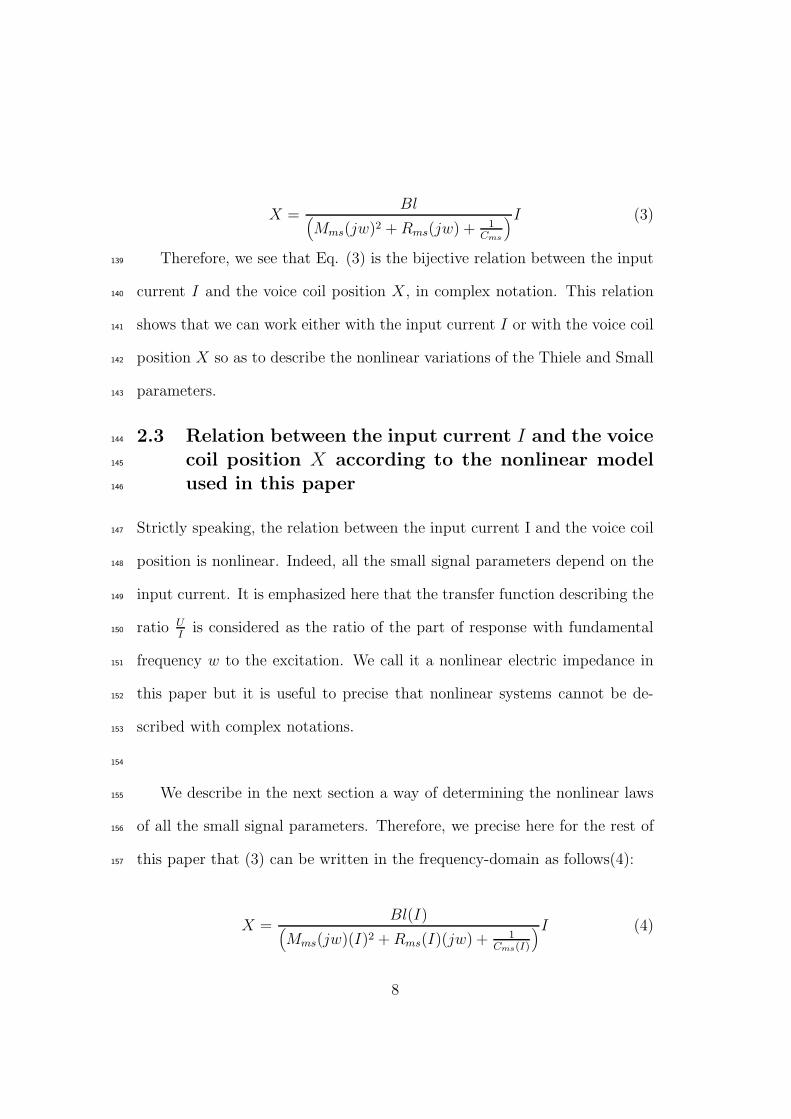
Therefore, we see that Eq. (3) is the bijective relation between the input139
current I and the voice coil position X, in complex notation. This relation140
shows that we can work either with the input current I or with the voice coil141
position X so as to describe the nonlinear variations of the Thiele and Small142
parameters.143
2.3 Relation between the input current I and the voice144
coil position X according to the nonlinear model145
used in this paper146
Strictly speaking, the relation between the input current I and the voice coil147
position is nonlinear. Indeed, all the small signal parameters depend on the148
input current. It is emphasized here that the transfer function describing the149
ratio UI
is considered as the ratio of the part of response with fundamental150
frequency w to the excitation. We call it a nonlinear electric impedance in151
this paper but it is useful to precise that nonlinear systems cannot be de-152
scribed with complex notations.153
154
We describe in the next section a way of determining the nonlinear laws155
of all the small signal parameters. Therefore, we precise here for the rest of156
this paper that (3) can be written in the frequency-domain as follows(4):157
X =Bl(I)
(
Mms(jw)(I)2 + Rms(I)(jw) + 1Cms(I)
)I (4)
8

It is noted that the determination of the small signal parameters can be158
determined in the frequency domain. We explain in next section how to find159
these variations.160
3 Determination of the nonlinear variations161
of the lumped parameters162
3.1 Principle of the measurement163
We have shown in the previous section that the nonlinear variations of the164
lumped parameters describing an electrodynamic loudspeaker depend on the165
input current. We explain now how to find these variations.166
The electrodynamic loudspeaker used is a boomer (mark: Eminence,167
number: beta 15 ). We use the electrical impedance of the electrodynamic168
loudspeaker because its measurement is very precise. Our measurement de-169
vice is a Wayne Kerr bridge which has an excellent precision (10−4Ω). This170
experimental devices is dedicated to the impedance measurement and func-171
tions as a classical impedance bridge.172
In order to measure the electrical impedance of a loudspeaker, it is mounted173
in a normalized plane in an anechoic room [23]. Dalmont [24] has shown that174
the acoustical impedance in these conditions is the same as the one when the175
loudspeaker is mounted in an infinite baffle in an anechoic room. We mea-176
sure the electrical impedance by varying the frequency and the coil current.177
So, we build an experimental impedance layer by using a Runge Kutta al-178
gorithm to determine all the experimental measured points. In other words,179
this measurement algorithm chooses the best measurement point according180
9

to the gradient method. Such a measurement method allows us to detect all181
the subtle effects due to the nonlinearities in electrodynamic loudspeakers.182
This algorithm has been improved in relation to the one used in a previ-183
ous paper. In the previous paper, the algorithm took some experimental184
points by using constant intensities. In other words, our measurement sys-185
tem used the algorithm of gradient only in two dimensions for one intensity186
and then it was repeated for another intensity. For example, an intensity187
was fixed (for example 50 mA), and a two-dimensional algortihm allowed us188
to determine the measurement points, that is to say, our algorithm auto-189
matically settled one intensity and took some experimental points by using190
a method based on the gradient method. In this paper, the algorithm uses191
a Runge Kutta algorithm in three dimensions (Ze,I,f) and we can rapidly192
obtain an impedance layer which is very precise. Consequently, the temporal193
effects can be neglected. A two-dimensional representation of the electrical194
impedance is shown in Fig. 2: the imaginary part is a function of the real195
part ( it is Nyquist diagram for different coil currents). We can say that the196
Wayne Kerr bridge cannot supply currents greater than 0.2A. Consequently,197
the parameter variations are determined in this current interval.198
Figure 3 confirms that the electrical impedance is a function of the input199
current.200
3.2 Determination of the nonlinear electrical impedance201
The next step is thus to determine the dependence of the small signal param-202
eters with the coil current so as to construct the nonlinear transfer function.203
10

Figure 3: Experimental three-dimensional representation of the modulus ofthe electrical impedance of the electrodynamic loudspeaker ( x : coil current0 A 0,2 A)(y : frequency 0 Hz 1000 Hz)(z: impedance 0Ω 30Ω)
For this purpose, we use the Nyquist diagram constructed previously. Five204
parameters (Bl(I), Rms(I), Cms(I), Mms(I), Le(I)) are assumed to vary with205
the coil current. Indeed, the electrical resistance does not depend on input206
current because our experimental measurements have been done with a sta-207
bilized temperature (the electrodynamic loudspeaker has been run in during208
24 hours before the experiment) and the eddy current resistance does not209
seem to vary with the input current I. In a first approximation, we use a210
polynomial writing to represent the dependence of the parameters with the211
coil current. We write:212
Bl(I) = Bl(1 + µBlI + µ2BlI
2 + ... + µnBlI
n) (5)213
Rms(I) = Rms(1 + µRmsI + µ2
RmsI2 + ... + µn
RmsIn) (6)
214
Cms(I) = Cms(1 + µCmsI + µ2
CmsI2 + ... + µn
CmsIn) (7)
215
Mms(I) = Mms(1 + µMmsI + µ2
MmsI2 + ... + µn
MmsIn) (8)
11

Le(i) = Le(1 + µLeI + µ2
LeI2 + ... + µn
LeIn) (9)
So the electrical impedance becomes :216
Ze(I) = Re +
∑ns=0 jLewRµ(µLe
I)s
Rµ +∑n
s=0 jLew(µLeI)s
+(∑n
s=0 Bl(µBlI)s)2
∑ns=0 jMmsw(µMms
I)s +∑n
s=0 Rms(µRmsI)s + 1
∑
n
s=0jwCms(µCms
I)s
(10)
We use a least square method to identify all the parameters; this method is217
based on Symplex algorithm. The Simplex method is a systematic procedure218
which selects the variable that will produce the largest change towards the219
minimum solution. This algorithm selects the best choice at each iteration220
without needing information from previous and future iterations. In our case,221
the principle of this algorithm is to minimize the difference D between the222
experimental and the theoretical Nyquist diagrams. Consequently, the two223
parameters which are minimized are the real part Real(I) and the imaginary224
part Imag(I) of the electrical impedance defined by eq. (11).225
Z(NL)e (I) = Real(I) + jImag(I) (11)
When the algorithm converges, we obtain the values of the parameters of226
the equations (5), (6), (7), (8) and (9).227
4 Experimental results228
When we take into account the variations of the small signal parameters229
with the coil current, the mean difference between the experimental and the230
12

Ranking Parameter Law of variation (100 Hz) D [Ω](100 Hz)1 Rms 1.1(1 + 4.09I − 8.36I2) 1.242 Bl 5.5(1 + 0.33I − 1.02I2) 1.673 Mms 0.009(1 + 0.56I − 0.22I2) 1.744 Cms 0.00013(1 + 2.02I − 9.3I2) 1.865 Le 0.0017(1 − 1.68I + 7.58I2) 1.98
Table 1: Ranking of the parameters according to their sensitivity to the leastsquare algorithm
theoretical values is 0,4Ω whereas the mean difference is 2,0Ω with Thiele and231
Small model with constant parameters. We present in table 1 the laws of232
variations of the five parameters that vary according to the coil current, and233
we give for each parameter the sensitivity to the least square. We propose234
a ranking of these parameters based on the criterion D. To get this ranking,235
we proceed as follows : we write that one parameter ( Le, Rms, Mms, Bl236
or Cms) is a function of the coil current. We input the polynomial in the237
theoretical impedance and we use the least square algorithm to determine at238
the value of the mean difference between the experimental impedance and239
the theoretical impedance. We obtain in this case the ranking shown in table240
1. Moreover, the value of the eddy current resistance is 2,2Ω and the value241
of the electrical resistance is 3,3Ω. The table 2 shows the laws of variations242
of Thiele and Small parameters. The representations of these variations are243
given in Figs 4, 5, 6, 7 and 8.244
13

0 0.05 0.1 0.15 0.2Coil Current @AD
0.92
0.94
0.96
0.98
1
Le
Le0
Figure 4: The ratio LeLe0
is a function of the coil current ( x : coil current 0A0,2A) (f=100Hz); Le0 = 0.0017H
0 0.05 0.1 0.15 0.2Coil Current @AD
11.005
1.011.015
1.021.025
Bl
Bl0
Figure 5: The ratio BlBl0
is a function of the coil current ( x : coil current 0A0,2A)(f=100Hz); Bl0 = 5.5Tm
0 0.05 0.1 0.15 0.2Coil Current @AD
11.021.041.061.08
1.1
Cm
sC
ms0
Figure 6: The ratio Cms/Cms0 is a function of the coil current ( x : coilcurrent 0A 0,2A)(f=100Hz); Cms0 = 0.00013m/N
14

0 0.05 0.1 0.15 0.2Coil Current @AD
1
1.1
1.2
1.3
1.4R
ms
Rm
s0
Figure 7: The ratio Rms
Rms0is a function of the coil current ( x : coil current
0A 0,2A)(f=100Hz); Rms0 = 1.1kg/s
0 0.05 0.1 0.15 0.2Coil Current @AD
11.021.041.061.08
1.1
Mm
sM
ms0
Figure 8: The ratio Mms
Mms0is a function of the coil current ( x : coil current
0A 0,2A)(f=100Hz);Mms0 = 0.009kg
15

4.1 Discussion245
The most sensitive parameter to the variations of the coil current is the246
equivalent damping parameter Rms. The parameter which is the less sensitive247
to the variations of the coil current is the inductance Le of the voice coil.248
However, though this inductance sensitiveness is rather weak, the relative249
variation of the inductance Le is rather important. In other words, even if250
the inductance Le is a parameter that contributes just a little to the variation251
of its electrical impedance, we see that its relative variation is important.252
Another interesting point can be adressed. With the values found in this253
paper, at 200Hz, we see that the eddy current resistance Rµ equals roughly254
wLe. We can conclude that the effects of the eddy currents become important255
from 200Hz for this electrodynamic loudspeaker.256
5 Study of the distortions created by the elec-257
trodynamic loudspeaker258
5.1 Obtaining the nonlinear differential equation259
The nonlinear differential equation describing the electrodynamic loudspeaker260
is given by Eq. (12). We use the parameter k = 1Cms
to solve it.261
a(i)d3x(t)
dt3+ b(i)
d2x(t)
dt2+ c(i)
dx(t)
dt+ d(i)x(t) = u(t) (12)
with262
a(i) =
(
Mms(1 + µMmsi + µ2
Mmsi2)
)
(Le(1 + µLei + µ2Lei
2))
Bl(1 + µBli + µ2Bli
2)(13)
263
b(i) =
(
(Mms(1 + µMmsi + µ2
Mmsi2)Re
)
Bl(1 + µBli + µ2Bli
2)
16

+
(
Rms(1 + µRmsi + µ2
Rmsi2)Re
)
Bl(1 + µBli + µ2Bli)
(14)
264
c(i) =Re
(
Rms(1 + µRmsi + µ2
Rmsi2)
)
+ (Bl(1 + µBli + µ2Bli
2))2
Bl(1 + µBli + µ2Bli
2)
+(Le(1 + µLei + µ2
Lei2))k(1 + µki + µ2
ki2)
Bl(1 + µBli + µ2Bli
2)(15)
265
d(i) =Re (k(1 + µki + µ2
ki2))
Bl(1 + µBli + µ2Bli
2)(16)
5.2 Solving the nonlinear differential equation266
The relation between the coil current i and the position of the voice coil x is267
nonlinear (Eq. (4)). Each small signal parameter is a function of the voice268
coil position and we obtain, for example, for one parameter :269
Rms(x) = Rms(1 + µRmsx + µ2
Rmsx2) (17)
with∣
∣
∣µ2Rms
∣
∣
∣ << |µRms| << 1 .270
If we assume that the input voltage u(t) is sinusoidal, in this case, the solu-271
tion of the nonlinear differential equation is a trigonometric expansion. The272
solution can be developed until the order 2 (µ2).273
x(t) = x0(t) + µx1(t) + µ2x2(t) + ... (18)
where x0(t) is the solution of the nonlinear differential equation of the elec-274
trodynamic loudspeaker when we neglect the terms with orders higher than275
zero, x1(t) is the solution of the nonlinear differential equation when we omit276
the terms with orders higher than one and smaller than one, x2(t) is the solu-277
tion of the nonlinear differential equation of the electrodynamic loudspeaker278
when we neglect the terms with orders smaller than two and higher than two.279
17

It can be noted that some methods like Volterra Series are interesting but280
do not show what parameters are really nonlinear. The way of solving the281
nonlinear differential equation is very important but we think that it is not282
the most important thing for characterizing electrodynamic loudspeakers.283
The real problem is to know what parameters vary and how. Furthermore,284
the ranking of these parameters according to the input current or frequency285
is of great importance. Indeed, we can think that if the structure of an286
electrodynamic loudspeaker must be improved, we must know all the defects287
in the motor or the suspensions.288
Let us consider now Eq. (12). The denominator in Eq. (12) contains289
a nonlinear term. Consequently, it is very difficult to solve this nonlinear290
differential equation with a nonlinear denominator. One possible solution is291
to approximate this denominator as follows :292
1
Bl(x)= Bl0 + Bl1x + Bl2x
2 + ... (19)
The previous relation is used as a simplification for solving numerically the293
nonlinear differential equation. Moreover, we can use a classical trigono-294
metric expansion to solve Eq. (12). In short, the solution of the nonlinear295
differential equation of the electrodynamic loudspeaker is296
x(t) = A cos(wt) + B sin(wt) + C cos(2wt) + D sin(2wt) + ... (20)
All the terms A,B,C,D,... are found numerically but an analytical solution297
is possible if the force factor is approximated. Indeed, the terms A and B298
can be found by inserting A cos(wt)+B sin(wt) in the equation (12) with an299
18

excitation u(t) equals to P sin(wt) where P is an amplitude. The terms C300
and D can be found by taking the terms with orders higher than one into301
account, etc...302
5.3 Theoretical results and position of the small signal303
parameters according to their created distortions304
We present the position of the small signal parameters according to their305
created distortions. For this purpose, we solve the nonlinear differential306
equation by using the serial expansion presented in the previous section but307
we take into account only one variation of a parameter at a time. Figure 9308
shows the created distortions by each Thiele and Small parameter. The level309
of the input voltage is 10V and the frequency of the excitation is 50Hz. We310
can see that for this electrodynamic loudspeaker, the nonlinear parameter311
which creates the most important second-harmonic is the inductance Le of312
the voice coil, and the nonlinear parameter which creates the most important313
third-harmonic is the equivalent damping parameter Rms. However, when314
the frequency of the excitation increases, the nonlinear parameters which315
create more distortions are not the same. Figure 10 presents the created316
distortions by each Thiele and Small parameter when the frequency of the317
excitation is 150 Hz. As shown in the previous figure, the level of the input318
voltage is 10V and the frequency of the excitation is 150 Hz. We see that319
the nonlinear parameter which creates the most important second-harmonic320
is the equivalent mass Mms and the nonlinear parameter which creates the321
more important third-harmonic is the damping parameter Rms. We sum up322
19

Figure 9: Theoretical spectrums of Thiele and Small parameters: the fre-quency of the excitation is 50Hz and the input voltage is 10V
Ranking ( 50 Hz) Parameter(harmonic 2) log[x]1 Le -3.22 Mms -4.93 Rms -6.84 Cms -7.75 Bl -7.8
Table 2: Ranking of the parameters according to their created distortions(the frequency of the excitation is 50 Hz)
all the results in tables 2, 3, 4 and 5.323
5.4 Discussion324
The previous section shows that the nonlinear parameters which create the325
most distortions are not those which are the most nonlinear according to the326
coil current. For example, figure 7 shows that the equivalent damping pa-327
rameter Rms is the most nonlinear parameter ( Rms varies a lot with the coil328
current ) but it is not the parameter which creates the most distortions. On329
the contrary, the inductance Le of the voice coil varies very little with the coil330
20

Figure 10: Theoretical spectrums of Thiele and Small parameters: the fre-quency of the excitation is 150Hz and the input voltage is 10V
Ranking ( 50 Hz) Parameter(harmonic 3) log[x]1 Rms -112 Bl -12.53 Cms -12.64 Le -12.95 Mms -14.6
Table 3: Ranking of the parameters according to their created distortions(the frequency of the excitation is 50 Hz)
Ranking ( 150 Hz) Parameter(harmonic 2) log[x]1 Mms -5.32 Le -6.43 Rms -7.74 Cms -8.25 Bl -8.4
Table 4: Ranking of the parameters according to their created distortions(the frequency of the excitation is 150 Hz)
21

Ranking ( 150 Hz) Parameter(harmonic 3) log[x]1 Rms -11.72 Le -12.63 Cms -14.24 Bl -155 Mms -15.1
Table 5: Ranking of the parameters according to their created distortions(the frequency of the excitation is 150 Hz)
current but at low frequency this parameter creates important distortions.331
Moreover, we see that the mechanical compliance Cms is not an important332
nonlinear parameter since it does not create important distortions. In ad-333
dition, the ranking of these nonlinearities depend also on input frequency.334
Such results are interesting for the design of electrodynamic loudspeakers.335
6 BEHAVIOR OF THE CREATED DISTOR-336
TIONS ACCORDING TO THE VARIA-337
TIONS OF THE INPUT VOLTAGE338
The previous section presents the ranking of the nonlinear Thiele and Small339
parameter according to the variation of the frequency excitation. The aim of340
this section is to show that the distortions created by the nonlinear param-341
eters are more sensitive than the fundamental component according to the342
variation of the input voltage. To show this, we solve the nonlinear differen-343
tial equation of the electrodynamic loudspeaker (12). We solve this equation344
by taking four different amplitudes for the excitation ( 1V, 5V, 10V, 50V )345
and we represent the spectrum in Fig. 11. The frequency of the excitation346
22

Figure 11: Theoretical spectrum : influence of the input voltage on thecreated harmonics
Harmonics 1V 5V 10V 50Vfirst-harmonic -3.8 -3 -2.8 -2.7second-harmonic -5.9 -5.6 -4.2 -3.4third-harmonic -15.8 -13.5 -13 -11.4
Table 6: Ranking of the parameters according to their created distortions(the input frequency is 100Hz)
is 100 Hz.347
7 CONCLUSION348
The aim of this paper was the study of the spectrum of the electrodynamic349
loudspeaker. The experimental method, based on the impedance measure-350
ment of an electrodynamic loudspeaker allows us to find all the variations351
of the Thiele and Small parameters. We can say that this experimental352
method can be used to characterize many transducers which are described353
with their electrical impedance. Indeed, an electrical impedance can be seen354
23

as a nonlinear transfer function which varies with the input current or the355
input voltage [25]. In section 2, we have presented a method to derive the356
coefficients of the nonlinear parameters based on Symplex algorithm. It is357
noted that a simplifying method has been used in a previous paper [10] and358
has been improved in this paper.359
The small signal coefficients, inserted in the differential equation of the360
electrodynamic loudspeaker enable us to find the generated harmonics. Many361
new results are discussed. The equivalent damping parameter is the param-362
eter which is the most nonlinear if we look at its relative variation according363
to the input current. However, it is not the parameter which creates the most364
important distortions. This result is important because it gives information365
about the way of manufacturing an electrodynamic loudspeaker.366
More generally, when we take into account the variations of the small367
signal parameters with the coil current, the mean difference between the368
experimental and the theoretical values is 0,4Ω , whereas the mean difference369
is 2,0Ω with Thiele and Small model with constant parameters.370
Another interesting result is the weak variation of the electrical induc-371
tance with the input current. It is noted that the electrodynamic loudspeaker372
characterized in this paper is a good one and is less nonlinear than a bad373
loudspeaker. However, we see that this weak variation creates important dis-374
tortions. This is why it can be very important to try to build electrodynamic375
loudspeakers with constant inductance.376
Furthermore, we have seen that these generated harmonics become more377
and more important when the input voltage increases. This result is in fact378
24

consistent with all the studies dealing with the modeling of nonlinear systems.379
This paper is a first step to derive and class the defects of electrodynamic380
loudspeakers. The experimental approach taken is certainly the more precise381
for characterizing the variation of a nonlinear transfer function according to382
the input level. We can say that such defects are very important to determine383
because they lower the quality of loudspeakers.384
8 ACKNOWLEDGMENT385
We thank James Blondeau for his help with the experimental manipulations.386
References
[1] A. N. Thiele, “Loudspeakers in vented boxes: Part 1 and 2,” in Loud-
speakers, vol. 1, New York: Audio Eng. Soc., 1978.
[2] W. Klippel, “Dynamic measurement and interpretation of the nonlinear
parameters of electrodynamic loudspeakers,” J. Audio Eng. Soc., vol. 38,
pp. 944–955, 1990.
[3] J. Borwick, Loudspeaker Measurements, in Loudspeaker and Headphone
Handbook. Focal Press, oxford ed., 2001.
[4] W. Klippel, “Loudspeaker nonlinearities - cause, parameters, symp-
toms,” J. Audio Eng. Soc., vol. 54, pp. 907–939, 2006.
[5] H. Suzuki and J. Tichy, “Radiation and diffraction effects by convex and
concave domes,” J. Audio Eng. Soc., vol. 29, pp. 873–881, 1981.
25

[6] N. Quaegebeur, A. Chaigne, and G. Lemarquand, “Transient model
radiation of asymetric sources: application to loudspeakers,” Applied
Acoustics, vol. doi:10.1016/japacoust.2009.10.003, 2009.
[7] G. Lemarquand and M. Bruneau, “Large bandwith loudspeaker emitting
coherent acoustic waves: nonlinear inter-modulation effects,” J. Audio
Eng. Soc., vol. 56, pp. 36–44, January 2007.
[8] A. Dobrucki, “Nontypical effects in an electrodynamic loudspeaker with
a nonhomogeneous magnetic field in the air gap and nonlinear suspen-
sion,” J. Audio Eng. Soc., vol. 42, pp. 565–576, 1994.
[9] J. Wright, “An empirical model for loudspeaker motor impedance,” J.
Audio Eng. Soc., pp. 749–754, October 1990.
[10] R. Ravaud, G. Lemarquand, and T. Roussel, “Time-varying non linear
modeling of electrodynamic loudspeakers,” Applied Acoustics, vol. 70,
pp. 450–458, 2009.
[11] A. J. M. Kaizer, “Modeling of the nonlinear response of an electrody-
namic loudspeaker by a volterra series expansion,” J. Audio Eng. Soc.,
vol. 35, pp. 421–433, June 1987.
[12] M. R. Gander, “Moving-coil loudspeaker topology as an indicator of
linear excursion capability,” J. Audio Eng. Soc., vol. 29, 1981.
[13] M. R. Gander, “Dynamic linearity and power compression in moving-
coil loudspeaker,” J. Audio Eng. Soc., pp. 627–646, September 1986.
26

[14] W. Leach, “Loudspeaker voice-coil inductance losses : Circuit models,
parameter estimation and effect on frequency response,” J. Audio Eng.
Soc., pp. 442–449, 2002.
[15] D. Clark, “Precision measurement of loudspeaker parameters,” J. Audio
Eng. Soc., pp. 129–141, March 1997.
[16] J. Vanderkooy, “A model of loudspeaker driver impedance incorporating
eddy currents in the pole structure,” J. Audio Eng. Soc., vol. 37, pp. 119–
128, 1989.
[17] G. Lemarquand, “Ironless loudspeakers,” IEEE Trans. Magn., vol. 43,
no. 8, pp. 3371–3374, 2007.
[18] B. Merit, G. Lemarquand, and V. Lemarquand, “In pursuit of increas-
ingly linear loudspeaker motors,” IEEE. Trans. Mag., vol. 45, no. 6,
pp. 2867–2870, 2009.
[19] M. Remy, G. Lemarquand, B. Castagnede, and G. Guyader, “Iron-
less and leakage free voice-coil motor made of bonded magnets,” IEEE
Trans. Magn., vol. 44, no. 11, 2008.
[20] R. Ravaud and G. Lemarquand, “Modelling an ironless loudspeaker by
using three-dimensional analytical approaches,” Progress in Electromag-
netics Research, PIER 91, pp. 53–68, 2009.
27

[21] R. Ravaud and G. Lemarquand, “Design of ironless loudspeakers with
ferrofluid seals: analytical study based on the coulombian model,”
Progress in Electromagnetics Research B, vol. 14, pp. 285–309, 2009.
[22] R. Ravaud, G. Lemarquand, and V. Lemarquand, “Magnetic pressure
and shape of ferrofluid seals in cylindrical structures,” J. Appl. Phys.,
vol. 106, no. 3, p. 34911, 2009.
[23] I. E. C, Sound. System. Equipment, Part 5: Loudspeaker. Edition 3.1,
11-09-2007.
[24] J. Dalmont, C. Nederveen, and N. Joly, “Radiation impedance of tubes
with different flanges:numerical and experimental investigations,” J. of
Sound and Vibration, vol. 244, no. 3, pp. 505–534, 2001.
[25] J. C. Gille, P. Decaulne, and M. Pelegrin, Systemes asservis non lin-
eaires. Bordas Editeur, Paris, France, 1981.
28