ramesh ppt2
DESCRIPTION
rtyiTRANSCRIPT

AN ADVANCED CURRENT CONTROL STRATEGY FOR THREE PHASE SHUNT
ACTIVE FILTER
NARASARAOPET ENGINEERING COLLEGE –NARASARAOPET
SUBMITTED BY
G. RAMESH BABU
Under the esteemed guidance of Y.RAJESH BABU M-tech,(PhD),
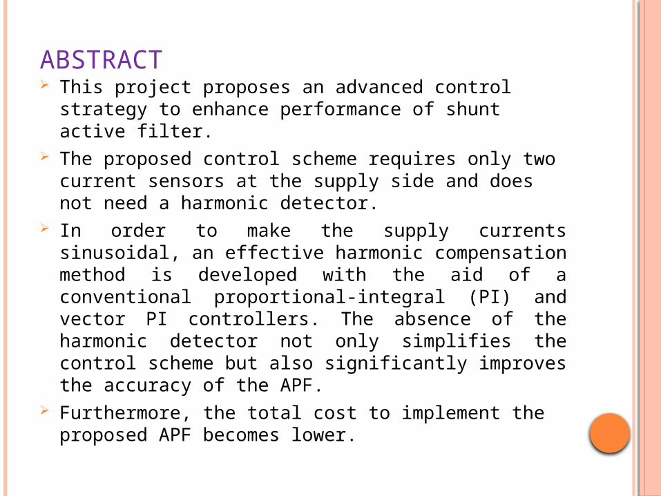
ABSTRACT This project proposes an advanced control strategy to enhance
performance of shunt active filter. The proposed control scheme requires only two current sensors at
the supply side and does not need a harmonic detector. In order to make the supply currents sinusoidal, an effective
harmonic compensation method is developed with the aid of a conventional proportional-integral (PI) and vector PI controllers. The absence of the harmonic detector not only simplifies the control scheme but also significantly improves the accuracy of the APF.
Furthermore, the total cost to implement the proposed APF becomes lower.
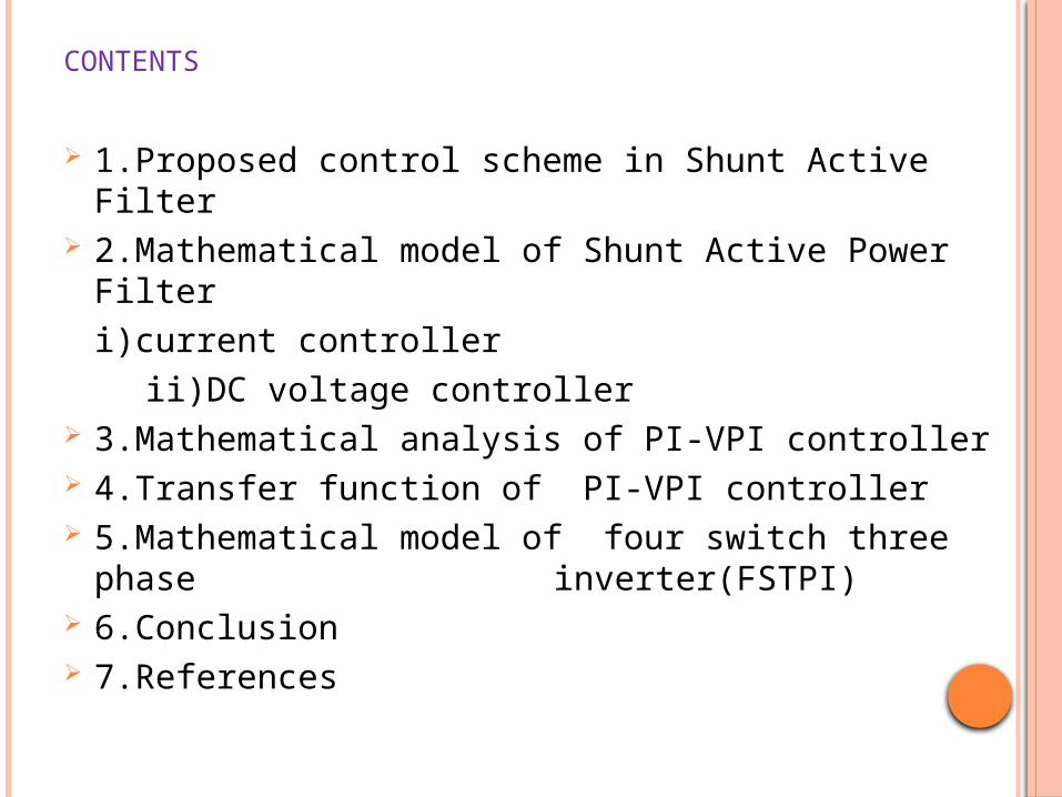
CONTENTS 1.Proposed control scheme in Shunt Active Filter 2.Mathematical model of Shunt Active Power Filter
i)current controller
ii)DC voltage controller 3.Mathematical analysis of PI-VPI controller 4.Transfer function of PI-VPI controller 5.Mathematical model of four switch three phase
inverter(FSTPI) 6.Conclusion 7.References
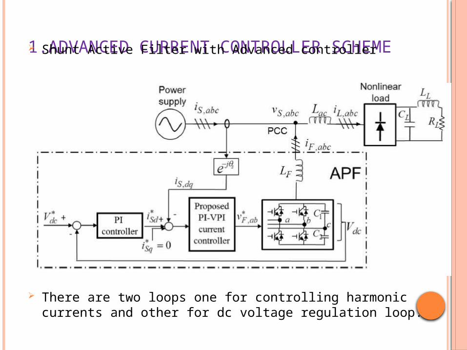
1.ADVANCED CURRENT CONTROLLER SCHEME Shunt Active Filter with Advanced controller
There are two loops one for controlling harmonic currents and other for dc voltage regulation loop.
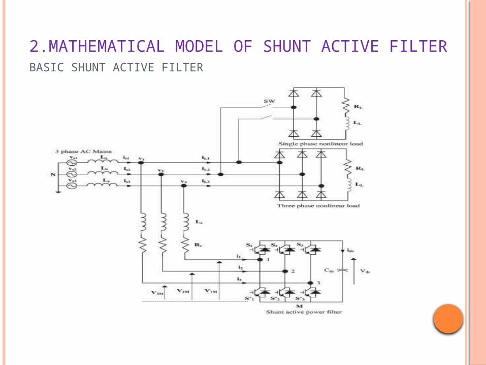
2.MATHEMATICAL MODEL OF SHUNT ACTIVE FILTERBASIC SHUNT ACTIVE FILTER
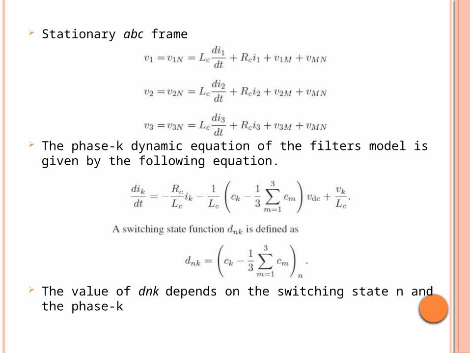
Stationary abc frame
The phase-k dynamic equation of the filters model is given by the following equation.
The value of dnk depends on the switching state n and the phase-k
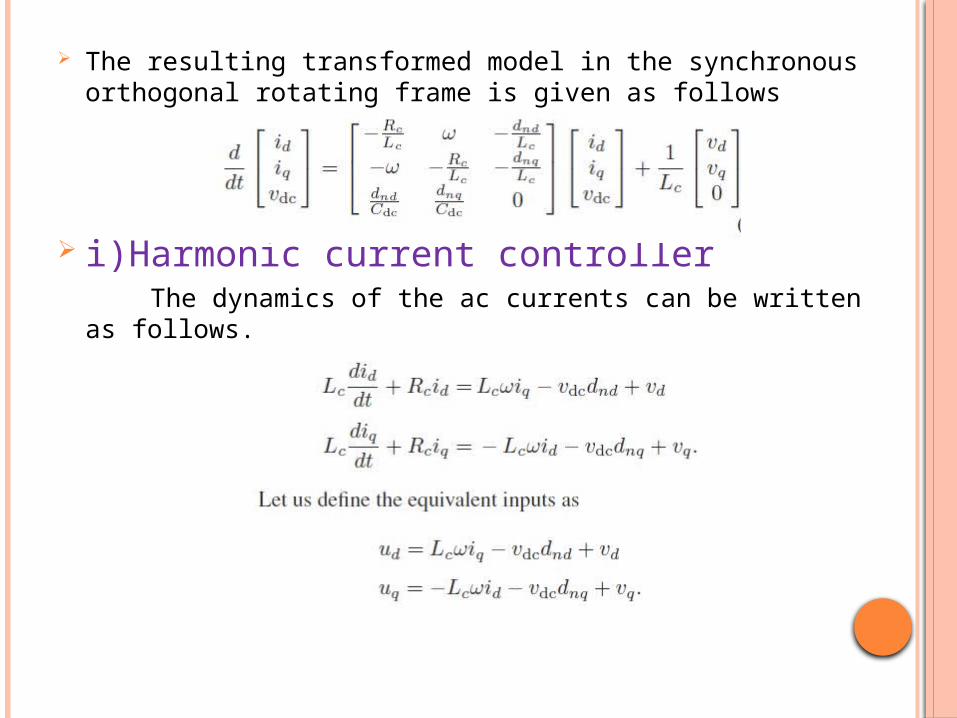
The resulting transformed model in the synchronous orthogonal rotating frame is given as follows
i)Harmonic current controller The dynamics of the ac currents can be written as follows.
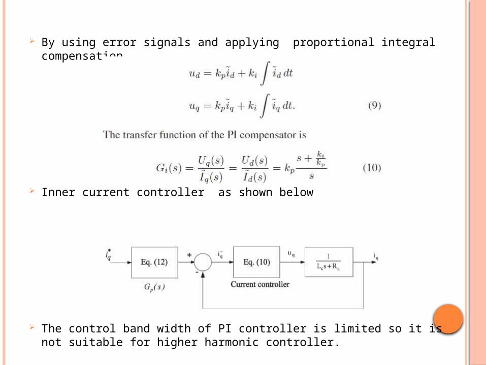
By using error signals and applying proportional integral compensation
Inner current controller as shown below
The control band width of PI controller is limited so it is not suitable for higher harmonic controller.
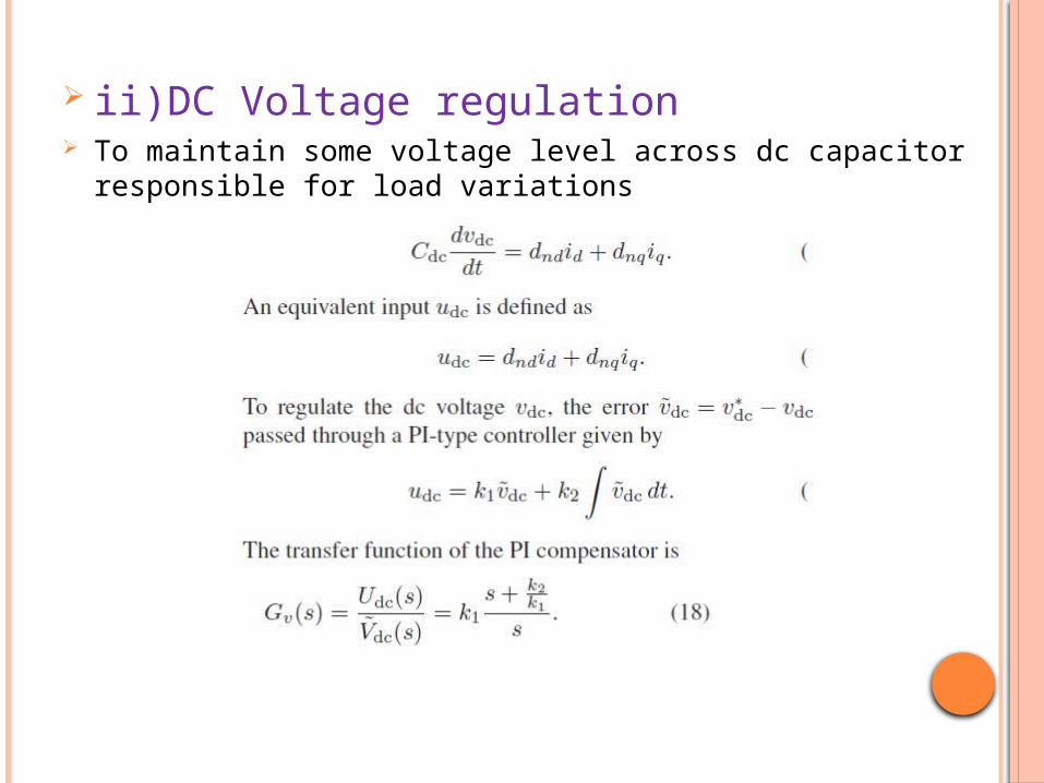
ii)DC Voltage regulation To maintain some voltage level across dc capacitor responsible for load
variations
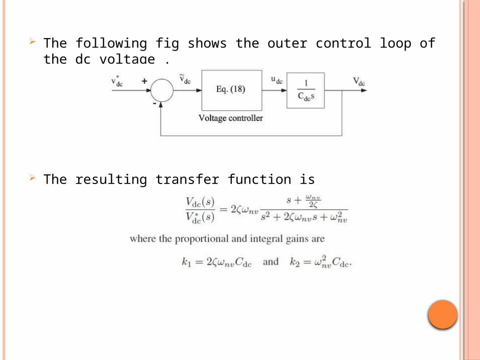
The following fig shows the outer control loop of the dc voltage .
The resulting transfer function is
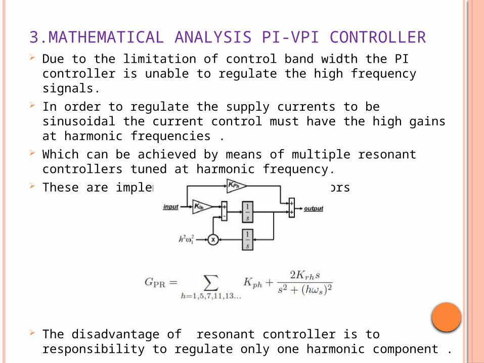
3.MATHEMATICAL ANALYSIS PI-VPI CONTROLLER Due to the limitation of control band width the PI controller is unable to
regulate the high frequency signals. In order to regulate the supply currents to be sinusoidal the current control
must have the high gains at harmonic frequencies . Which can be achieved by means of multiple resonant controllers tuned at
harmonic frequency. These are implemented with two integrators
The disadvantage of resonant controller is to responsibility to regulate only one harmonic component .
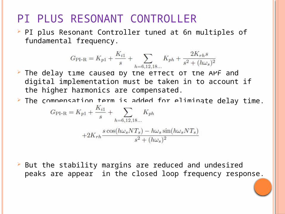
PI PLUS RESONANT CONTROLLER PI plus Resonant Controller tuned at 6n multiples of fundamental
frequency.
The delay time caused by the effect of the APF and digital implementation must be taken in to account if the higher harmonics are compensated.
The compensation term is added for eliminate delay time.
But the stability margins are reduced and undesired peaks are appear in the closed loop frequency response.
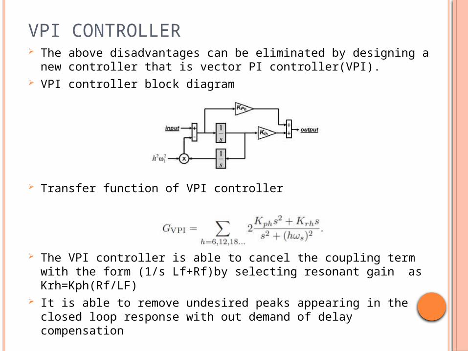
VPI CONTROLLER The above disadvantages can be eliminated by designing a
new controller that is vector PI controller(VPI). VPI controller block diagram
Transfer function of VPI controller
The VPI controller is able to cancel the coupling term with the form (1/s Lf+Rf)by selecting resonant gain as Krh=Kph(Rf/LF)
It is able to remove undesired peaks appearing in the closed loop response with out demand of delay compensation
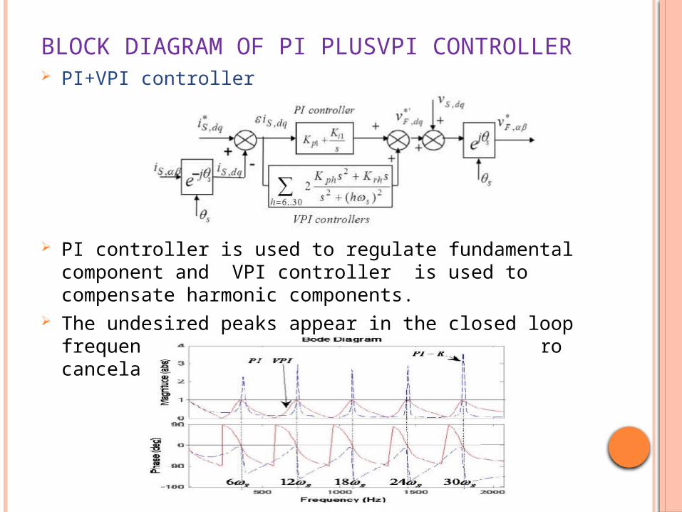
BLOCK DIAGRAM OF PI PLUSVPI CONTROLLER PI+VPI controller
PI controller is used to regulate fundamental component and VPI controller is used to compensate harmonic components.
The undesired peaks appear in the closed loop frequency response preventing with pole zero cancelation capability with inductor Lf
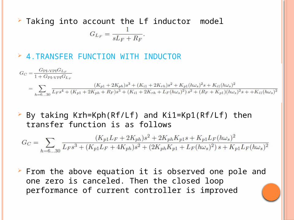
Taking into account the Lf inductor model
4.TRANSFER FUNCTION WITH INDUCTOR
By taking Krh=Kph(Rf/Lf) and Ki1=Kp1(Rf/Lf) then transfer function is as follows
From the above equation it is observed one pole and one zero is canceled. Then the closed loop performance of current controller is improved
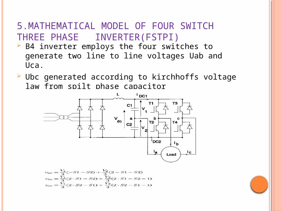
5.MATHEMATICAL MODEL OF FOUR SWITCH THREE PHASE INVERTER(FSTPI) B4 inverter employs the four switches to generate two line to line
voltages Uab and Uca. Ubc generated according to kirchhoffs voltage law from spilt phase
capacitor
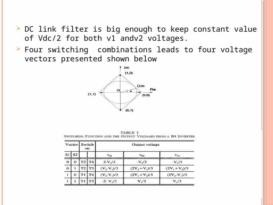
DC link filter is big enough to keep constant value of Vdc/2 for both v1 andv2 voltages.
Four switching combinations leads to four voltage vectors presented shown below
6.CONCLUSION From the above discussion it can be observed that PI controller is
only used for limited range of frequencies(band width).So it is not suitable for higher order harmonic compensation.
PI plus Resonant controller is used for compensating the harmonic currents. But in the closed loop frequency response an undesirable peaks are appeared.
The pole zero cancellation capability can be obtained with the help of PI plus VPI controller then closed loop frequency response and the stability of the system can be improved.
In this two leg three phase inverter can be used to reduce the over all cost of the system.
7.REFERENCES [1] Recommended Practice for Harmonic Control in Electric Power
Systems, IEEE Std. 519-1992, 1992. [2] Limits for Harmonic Current Emission, IEC 61000-3-2, 2001. [3] H. Akagi, “New trends in active filters for power conditioning,” IEEE
Trans. Ind. Appl., vol. 32, no. 2, pp. 1312–1332, Nov./Dec. 1996. [4] F. Z. Peng, “Application issues of active power filters,” IEEE Ind. Appl.
Mag., vol. 4, no. 5, pp. 21–30, Sep./Oct. 1998. [5] H. Akagi, E. H. Watanabe, and M. Aredes, Instantaneous Power
Theory
and Applications to Power Conditioning, M. E. El-Hawari, Ed. New York: Wiley, 2007.
[6] S. Buso, L. Malesani, and P. Mattavelli, “Comparison of current control techniques for active filters applications,” IEEE Trans. Ind. Electron., vol. 45, no. 5, pp. 722–729, Oct. 1998.
[7] L.Malesani, P. Mattavelli, and S. Buso, “Robust dead-beat current control for PWM rectifiers and active filters,” IEEE Trans. Ind. Appl., vol. 35,no. 3, pp. 613–620, May/Jun. 1999.

THANK YOU