rain water harvesting
DESCRIPTION
Wavin Rain Water Harvest Installation guideTRANSCRIPT

FOR RESIDENTIAL,
COMMERCIAL AND
INDUSTRIAL APPLICATIONS
AquaCell® & Garastor® StormwaterManagement Systems
Product andInstallation Guide
Intelligent Solutions for Below Ground Projects
CI/SfB(52.5) (90.51)
September 2004 WM417
Uniclass EPICJR12/JS10 L731/L71121/L2123 J3413 X721

CUSTOMER SERVICES 01249 766611
TECHNICAL ENQUIRIES01249 766655
TECHNICAL FAX 01249 766653
STORMWATER MANAGEMENT SYSTEMSIntroduction to OSMA - from Wavin
2
From WavinOSMA
OSMA, from Wavin Plastics Limited, is
the leading name in plastic systems for
building, construction and utilities. The
OSMA product range is unrivalled in
scope and quality, covering:
Above Ground systems
Plumbing and Heating systems
Below Ground Drainage systems
Water Management systems
Ducting systems
Water and Gas Distribution systems
Quality assured products
OSMA systems are the benchmark for
excellence and product innovation:
precision-manufactured in the UK using
the most advanced injection moulding
and extrusion machines. All products
comply with or exceed relevant British
and European standards to ensure
reliability and long-lasting service.
Intelligent connections
OSMA systems offer integrated solutions.
This enables specifiers and installers to
assemble complete drainage, plumbing
and heating, and pressure pipe systems
from a single source, with complete
confidence in compatibility and
performance.
All systems are backed by comprehensive
technical support and a nationwide
distribution network to ensure availability
when and where required.
Wavin is a leading European manufacturer
of industrial plastic products, and one of
the largest producers of plastic pipe and
fittings in the world.
Wavin is credited with inventing and
pioneering the use of plastic pipe
for water distribution in the mid 1950s.
Constant research and development has
enabled Wavin to maintain its position at
the forefront of plastics technology.
Environmental responsibility
Wavin Plastics Limited has BS EN ISO
9001: 2000 BSI status and was the
first plastic pipe manufacturer to be
accredited to BS EN ISO 14001
Environmental Management Systems.
Wavin Plastics Limited is committed to
environmental responsibility, and is a
leading pioneer of systems to conserve
and control water. In production,
the Company recycles the majority
of waste materials, and sets annual
targets for energy efficiency audited by
the certifying body.
Passion and resourcefulness
All Wavin personnel are committed to
providing a comprehensive, responsive
service – and are passionate about
delivering total Customer satisfaction.
Wavin Plastics Limited maintains an
industry-wide dialogue and rigorous
assessment of all procedures to ensure
that Wavin product development and
product support accurately addresses
the needs of all Customers – today and
into the future.

www.wavin.co.uk
STORMWATER MANAGEMENT SYSTEMSIntroduction to OSMA from Wavin ■ Contents
STORMWATER MANAGEMENT SYSTEMSContents
STORMWATER MANAGEMENT SYSTEMS Product & Installation Guide 2004
General Introduction 4
Introduction to AquaCell 5AquaCell System Overview 6
How it Works 6Key Benefits 6
AquaCell Principal Components 7
Typical Soakaway Installation Method 8
Typical Storage Tank Installation
Method 9
Typical Silt Trap Installation Method
& Air Vent Design 10
Typical Connections to AquaCell 11
Typical Air Vent Connections 12
Typical Manifold Configuration 13
Typical Soakaway Detail: Non-Traffic
Loading 14
Typical Soakaway Detail: Highway 15
Typical On-Line Water Storage Detail 16
Typical Off-Line Storage Detail 17
Hydraulically Designed On-Line Water
Storage System Installed Off-Line 18
Typical Soakaway Detail with Silt Trap 19
Contents
Introduction to Garastor 20Garastor System Overview 21
Garastor Principal Components 22
Typical Garastor Installation Methods 23
Case Studies 24
Notes 25
Technical Advice and Assistance 27
Further information
The following related publications are
available for OSMA Stormwater
Management systems:
Design and Installation Manual
Trade Price List
To obtain copies, please contact:
Literature requests
Tel: 01249 766333
Fax: 01249 766332
3
CUSTOMER SERVICES 01249 766611
TECHNICAL ENQUIRIES01249 766655
TECHNICAL FAX 01249 766653
STORMWATER MANAGEMENT SYSTEMSGeneral introduction
4
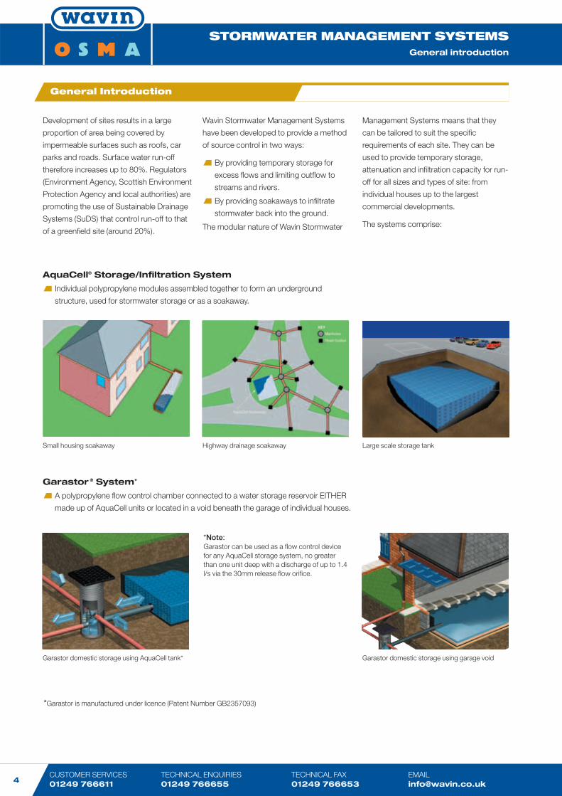
Development of sites results in a large
proportion of area being covered by
impermeable surfaces such as roofs, car
parks and roads. Surface water run-off
therefore increases up to 80%. Regulators
(Environment Agency, Scottish Environment
Protection Agency and local authorities) are
promoting the use of Sustainable Drainage
Systems (SuDS) that control run-off to that
of a greenfield site (around 20%).
Wavin Stormwater Management Systems
have been developed to provide a method
of source control in two ways:
By providing temporary storage for
excess flows and limiting outflow to
streams and rivers.
By providing soakaways to infiltrate
stormwater back into the ground.
The modular nature of Wavin Stormwater
AquaCell® Storage/Infiltration System
Individual polypropylene modules assembled together to form an underground
structure, used for stormwater storage or as a soakaway.
Management Systems means that they
can be tailored to suit the specific
requirements of each site. They can be
used to provide temporary storage,
attenuation and infiltration capacity for run-
off for all sizes and types of site: from
individual houses up to the largest
commercial developments.
The systems comprise:
General Introduction
*Note:Garastor can be used as a flow control devicefor any AquaCell storage system, no greaterthan one unit deep with a discharge of up to 1.4l/s via the 30mm release flow orifice.
Garastor ® System*
A polypropylene flow control chamber connected to a water storage reservoir EITHER
made up of AquaCell units or located in a void beneath the garage of individual houses.
Small housing soakaway Highway drainage soakaway Large scale storage tank
Garastor domestic storage using AquaCell tank* Garastor domestic storage using garage void
*Garastor is manufactured under licence (Patent Number GB2357093)

www.wavin.co.uk
STORMWATER MANAGEMENT SYSTEMSGeneral Introduction ■ Introduction to AquaCell®
STORMWATER MANAGEMENT SYSTEMSIntroduction to AquaCell
5
STORMWATER MANAGEMENT SYSTEMS Product & Installation Guide 2004
OSMA AquaCell StormwaterManagement System
Comprises individual infiltration modules
assembled together to form an
underground structure which can either be
used for stormwater storage or as an
alternative to domestic soakaways.
The AquaCell Stormwater Management
System is fully BBA (British Board of
Agrément) approved, Certificate No.
03/4018, and can meet with the Technical
Requirements of NHBC.
Heavy storms and major cloudbursts are
becoming more frequent, resulting in ever
increasing volumes of stormwater flowing
into conventional drainage systems and
water courses. When the capacities of
these systems are exceeded the
consequences can be dramatic and
damaging.
Stormwater must be controlled; either by
limiting the outflow and providing
temporary storage or where the ground
conditions are suitable, providing
soakaways for the stormwater to infiltrate
back into the surrounding ground.
This has the added benefit of recharging
the local groundwater.
Both options can be achieved using the
OSMA AquaCell Stormwater Management
System.
Introduction to AquaCell
Large scale AquaCell storage tank
Domestic AquaCell soakaway
CUSTOMER SERVICES 01249 766611
TECHNICAL ENQUIRIES01249 766655
TECHNICAL FAX 01249 766653
STORMWATER MANAGEMENT SYSTEMSAquaCell System Overview ■ How it works ■ Key benefits
6
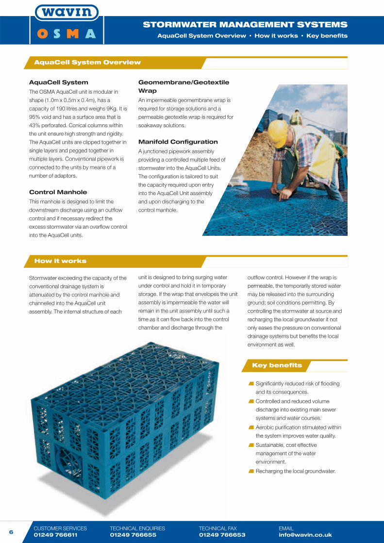
AquaCell System
The OSMA AquaCell unit is modular in
shape (1.0m x 0.5m x 0.4m), has a
capacity of 190 litres and weighs 9Kg. It is
95% void and has a surface area that is
43% perforated. Conical columns within
the unit ensure high strength and rigidity.
The AquaCell units are clipped together in
single layers and pegged together in
multiple layers. Conventional pipework is
connected to the units by means of a
number of adaptors.
Control Manhole
This manhole is designed to limit the
downstream discharge using an outflow
control and if necessary redirect the
excess stormwater via an overflow control
into the AquaCell units.
Stormwater exceeding the capacity of the
conventional drainage system is
attenuated by the control manhole and
channelled into the AquaCell unit
assembly. The internal structure of each
outflow control. However if the wrap is
permeable, the temporarily stored water
may be released into the surrounding
ground; soil conditions permitting. By
controlling the stormwater at source and
recharging the local groundwater it not
only eases the pressure on conventional
drainage systems but benefits the local
environment as well.
Geomembrane/GeotextileWrap
An impermeable geomembrane wrap is
required for storage solutions and a
permeable geotextile wrap is required for
soakaway solutions.
Manifold Configuration
A junctioned pipework assembly
providing a controlled multiple feed of
stormwater into the AquaCell Units.
The configuration is tailored to suit
the capacity required upon entry
into the AquaCell Unit assembly
and upon discharging to the
control manhole.
AquaCell System Overview
How it works
Significantly reduced risk of flooding
and its consequences.
Controlled and reduced volume
discharge into existing main sewer
systems and water courses.
Aerobic purification stimulated within
the system improves water quality.
Sustainable, cost effective
management of the water
environment.
Recharging the local groundwater.
Key benefits
unit is designed to bring surging water
under control and hold it in temporary
storage. If the wrap that envelopes the unit
assembly is impermeable the water will
remain in the unit assembly until such a
time as it can flow back into the control
chamber and discharge through the
www.wavin.co.uk
STORMWATER MANAGEMENT SYSTEMSOverview ■ How it works ■ Key benefits ■ Principal Components
STORMWATER MANAGEMENT SYSTEMSAquaCell Principal Components
7
STORMWATER MANAGEMENT SYSTEMS Product & Installation Guide 2004
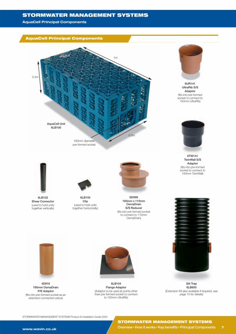
AquaCell Principal Components
6LB104Flange Adaptor
(Adaptor to be used at points otherthan pre-formed socket to connect
to 150mm UltraRib)
4D916160mm OsmaDrain
P/E Adaptor(fits into pre-formed socket as an
extension connection piece)
6LB102Shear Connector(used to hold unitstogether vertically)
6TW141TwinWall S/S
Adaptor(fits into pre-formedsocket to connect to
150mm TwinWall)
6UR141UltraRib S/S
Adaptor(fits into pre-formedsocket to connect to
150mm UltraRib)
6D099160mm x 110mm
OsmaDrainS/S Reducer
(fits into pre-formed socketto connect to 110mm
OsmaDrain)
AquaCell Unit6LB100
0.5m
1m
0.4m
Silt Trap6LB600
(Extension Kit also available if required, seepage 10 for details)
160mm diameterpre-formed socket
6LB105Clip
(used to hold unitstogether horizontally)
CUSTOMER SERVICES 01249 766611
TECHNICAL ENQUIRIES01249 766655
TECHNICAL FAX 01249 766653
STORMWATER MANAGEMENT SYSTEMSTypical Soakaway Installation Method
8
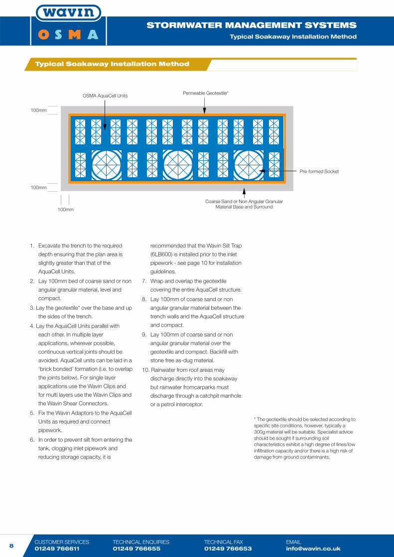
OSMA AquaCell Units Permeable Geotextile*
Coarse Sand or Non Angular Granular Material Base and Surround
100mm
100mm
100mm
Pre-formed Socket
Typical Soakaway Installation Method
1. Excavate the trench to the required
depth ensuring that the plan area is
slightly greater than that of the
AquaCell Units.
2. Lay 100mm bed of coarse sand or non
angular granular material, level and
compact.
3. Lay the geotextile* over the base and up
the sides of the trench.
4. Lay the AquaCell Units parallel with
each other. In multiple layer
applications, wherever possible,
continuous vertical joints should be
avoided. AquaCell units can be laid in a
‘brick bonded’ formation (i.e. to overlap
the joints below). For single layer
applications use the Wavin Clips and
for multi layers use the Wavin Clips and
the Wavin Shear Connectors.
5. Fix the Wavin Adaptors to the AquaCell
Units as required and connect
pipework.
6. In order to prevent silt from entering the
tank, clogging inlet pipework and
reducing storage capacity, it is
recommended that the Wavin Silt Trap
(6LB600) is installed prior to the inlet
pipework - see page 10 for installation
guidelines.
7. Wrap and overlap the geotextile
covering the entire AquaCell structure.
8. Lay 100mm of coarse sand or non
angular granular material between the
trench walls and the AquaCell structure
and compact.
9. Lay 100mm of coarse sand or non
angular granular material over the
geotextile and compact. Backfill with
stone free as-dug material.
10. Rainwater from roof areas may
discharge directly into the soakaway
but rainwater fromcarparks must
discharge through a catchpit manhole
or a petrol interceptor.
* The geotextile should be selected according tospecific site conditions, however, typically a300g material will be suitable. Specialist adviceshould be sought if surrounding soilcharacteristics exhibit a high degree of fines/lowinfiltration capacity and/or there is a high risk ofdamage from ground contaminants.
www.wavin.co.uk
STORMWATER MANAGEMENT SYSTEMSSoakaway Installation ■ Storage Tank Installation
STORMWATER MANAGEMENT SYSTEMSTypical Storage Tank Installation Method
9
STORMWATER MANAGEMENT SYSTEMS Product & Installation Guide 2004
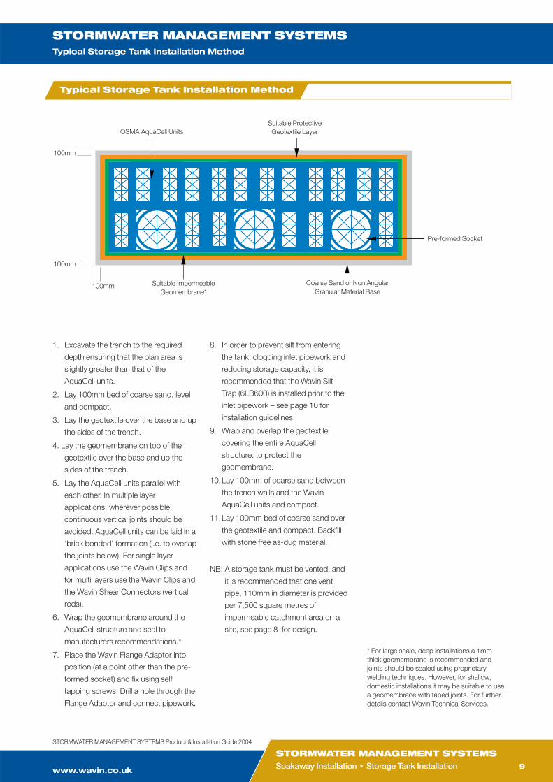
Typical Storage Tank Installation Method
1. Excavate the trench to the required
depth ensuring that the plan area is
slightly greater than that of the
AquaCell units.
2. Lay 100mm bed of coarse sand, level
and compact.
3. Lay the geotextile over the base and up
the sides of the trench.
4. Lay the geomembrane on top of the
geotextile over the base and up the
sides of the trench.
5. Lay the AquaCell units parallel with
each other. In multiple layer
applications, wherever possible,
continuous vertical joints should be
avoided. AquaCell units can be laid in a
‘brick bonded’ formation (i.e. to overlap
the joints below). For single layer
applications use the Wavin Clips and
for multi layers use the Wavin Clips and
the Wavin Shear Connectors (vertical
rods).
6. Wrap the geomembrane around the
AquaCell structure and seal to
manufacturers recommendations.*
7. Place the Wavin Flange Adaptor into
position (at a point other than the pre-
formed socket) and fix using self
tapping screws. Drill a hole through the
Flange Adaptor and connect pipework.
8. In order to prevent silt from entering
the tank, clogging inlet pipework and
reducing storage capacity, it is
recommended that the Wavin Silt
Trap (6LB600) is installed prior to the
inlet pipework – see page 10 for
installation guidelines.
9. Wrap and overlap the geotextile
covering the entire AquaCell
structure, to protect the
geomembrane.
10.Lay 100mm of coarse sand between
the trench walls and the Wavin
AquaCell units and compact.
11.Lay 100mm bed of coarse sand over
the geotextile and compact. Backfill
with stone free as-dug material.
NB: A storage tank must be vented, and
it is recommended that one vent
pipe, 110mm in diameter is provided
per 7,500 square metres of
impermeable catchment area on a
site, see page 8 for design.
OSMA AquaCell UnitsSuitable ProtectiveGeotextile Layer
Coarse Sand or Non Angular Granular Material Base
Suitable ImpermeableGeomembrane*
100mm
100mm
Pre-formed Socket
100mm
* For large scale, deep installations a 1mmthick geomembrane is recommended andjoints should be sealed using proprietarywelding techniques. However, for shallow,domestic installations it may be suitable to usea geomembrane with taped joints. For furtherdetails contact Wavin Technical Services.
CUSTOMER SERVICES 01249 766611
TECHNICAL ENQUIRIES01249 766655
TECHNICAL FAX 01249 766653
STORMWATER MANAGEMENT SYSTEMSTypical Silt Trap Installation Method ■ Typical Air Vent Design
10
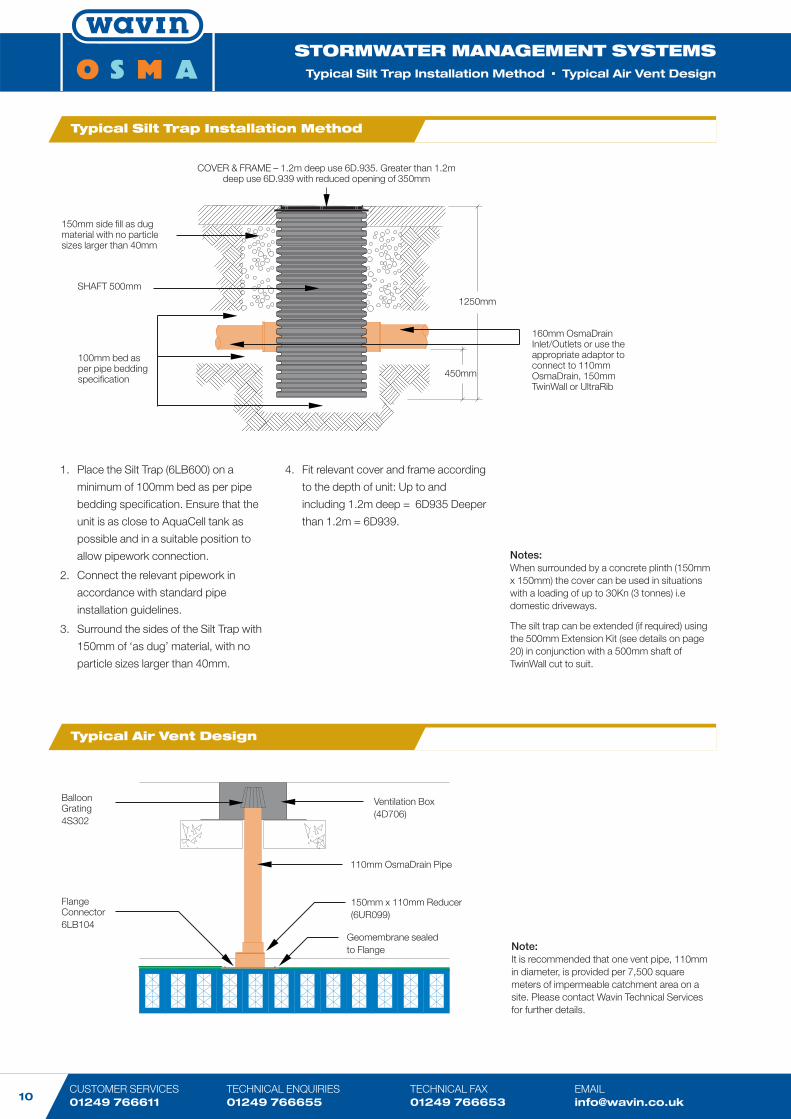
Typical Silt Trap Installation Method
Typical Air Vent Design
1. Place the Silt Trap (6LB600) on a
minimum of 100mm bed as per pipe
bedding specification. Ensure that the
unit is as close to AquaCell tank as
possible and in a suitable position to
allow pipework connection.
2. Connect the relevant pipework in
accordance with standard pipe
installation guidelines.
3. Surround the sides of the Silt Trap with
150mm of ‘as dug’ material, with no
particle sizes larger than 40mm.
4. Fit relevant cover and frame according
to the depth of unit: Up to and
including 1.2m deep = 6D935 Deeper
than 1.2m = 6D939.
COVER & FRAME – 1.2m deep use 6D.935. Greater than 1.2mdeep use 6D.939 with reduced opening of 350mm
160mm OsmaDrainInlet/Outlets or use theappropriate adaptor toconnect to 110mmOsmaDrain, 150mmTwinWall or UltraRib
150mm side fill as dugmaterial with no particlesizes larger than 40mm
SHAFT 500mm
450mm
1250mm
100mm bed asper pipe beddingspecification
BalloonGrating4S302
Ventilation Box(4D706)
FlangeConnector6LB104
110mm OsmaDrain Pipe
150mm x 110mm Reducer(6UR099)
Geomembrane sealed to Flange Note:
It is recommended that one vent pipe, 110mmin diameter, is provided per 7,500 squaremeters of impermeable catchment area on asite. Please contact Wavin Technical Servicesfor further details.
Notes:When surrounded by a concrete plinth (150mmx 150mm) the cover can be used in situationswith a loading of up to 30Kn (3 tonnes) i.edomestic driveways.
The silt trap can be extended (if required) usingthe 500mm Extension Kit (see details on page20) in conjunction with a 500mm shaft ofTwinWall cut to suit.
www.wavin.co.uk
STORMWATER MANAGEMENT SYSTEMSSilt Trap Installation ■ Air Vent Design ■ Connections to AquaCell
STORMWATER MANAGEMENT SYSTEMSTypical Connections to AquaCell
11
STORMWATER MANAGEMENT SYSTEMS Product & Installation Guide 2004
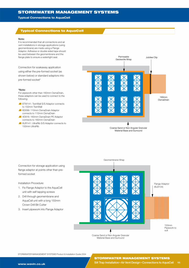
Typical Connections to AquaCell
Note: It is recommended that all connections and airvent installations in storage applications (usinggeomembrane) are made using a FlangeAdaptor. Adhesive or double sided tape shouldbe used between the geomembrane and theflange plate to ensure a watertight seal. Permeable
Geotextile WrapJubilee Clip
160mm OsmaDrain
Coarse Sand or Non Angular Granular Material Base and Surround
Connection for soakaway application
using either the pre-formed socket (as
shown below) or standard adaptors into
pre-formed socket*
*Note:For pipework other than 160mm OsmaDrain,these adaptors can be used to connect to thefollowing:
6TW141: TwinWall S/S Adaptor connects to 150mm TwinWall6D099: 110mm OsmaDrain Adaptor connects to 110mm OsmaDrain4D916: 160mm OsmaDrain PE Adaptorconnects to 160mm OsmaDrain6UR141: UltraRib S/S Adaptor connects to150mm UltraRib
Connection for storage application using
flange adaptor at points other than pre-
formed socket
Installation Procedure:
1. Fix Flange Adaptor to the AquaCell
unit with self tapping screws
2. Drill through geomembrane and
AquaCell unit with a long 150mm
Crown Drill Bit Cutter
3. Insert pipework into Flange Adaptor
Geomembrane Wrap
Flange Adaptor(6LB104)
Coarse Sand or Non Angular Granular Material Base and Surround
150mmPipework tosuit
CUSTOMER SERVICES 01249 766611
TECHNICAL ENQUIRIES01249 766655
TECHNICAL FAX 01249 766653
STORMWATER MANAGEMENT SYSTEMSTypical Air Vent Connections
12
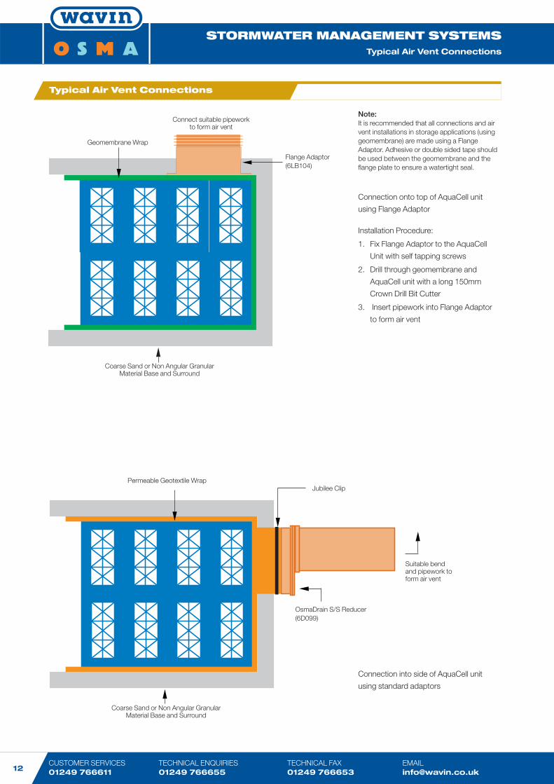
Geomembrane Wrap
Flange Adaptor(6LB104)
Coarse Sand or Non Angular Granular Material Base and Surround
Connect suitable pipework to form air vent
Permeable Geotextile WrapJubilee Clip
Suitable bendand pipework toform air vent
OsmaDrain S/S Reducer(6D099)
Coarse Sand or Non Angular Granular Material Base and Surround
Typical Air Vent Connections
Note: It is recommended that all connections and airvent installations in storage applications (usinggeomembrane) are made using a FlangeAdaptor. Adhesive or double sided tape shouldbe used between the geomembrane and theflange plate to ensure a watertight seal.
Connection onto top of AquaCell unit
using Flange Adaptor
Installation Procedure:
1. Fix Flange Adaptor to the AquaCell
Unit with self tapping screws
2. Drill through geomembrane and
AquaCell unit with a long 150mm
Crown Drill Bit Cutter
3. Insert pipework into Flange Adaptor
to form air vent
Connection into side of AquaCell unit
using standard adaptors
www.wavin.co.uk
STORMWATER MANAGEMENT SYSTEMSTypical Air Vent Connections ■ Typical Manifold Configuration
STORMWATER MANAGEMENT SYSTEMSTypical Manifold Configuration
13
STORMWATER MANAGEMENT SYSTEMS Product & Installation Guide 2004
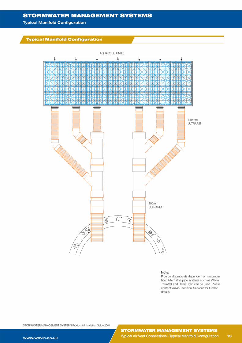
AQUACELL UNITS
150mm ULTRARIB
300mmULTRARIB
Note: Pipe configuration is dependent on maximumflow. Alternative pipe systems such as WavinTwinWall and OsmaDrain can be used. Pleasecontact Wavin Technical Services for furtherdetails.
Typical Manifold Configuration
CUSTOMER SERVICES 01249 766611
TECHNICAL ENQUIRIES01249 766655
TECHNICAL FAX 01249 766653
STORMWATER MANAGEMENT SYSTEMSTypical Soakaway Detail: Non-Traffic Loading
14
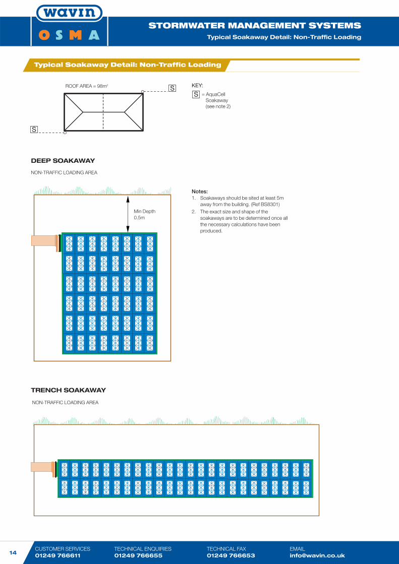
ROOF AREA = 98m2
S
S
TRENCH SOAKAWAY
Notes:1. Soakaways should be sited at least 5m
away from the building. (Ref BS8301)2. The exact size and shape of the
soakaways are to be determined once allthe necessary calculations have been produced.
NON-TRAFFIC LOADING AREA
NON-TRAFFIC LOADING AREA
Min Depth0.5m
KEY:
= AquaCell Soakaway(see note 2)
S
Typical Soakaway Detail: Non-Traffic Loading
DEEP SOAKAWAY
www.wavin.co.uk
STORMWATER MANAGEMENT SYSTEMSSoakaway Details: Non-Traffic Loading ■ Highway
STORMWATER MANAGEMENT SYSTEMSTypical Soakaway Detail - Highway
15
STORMWATER MANAGEMENT SYSTEMS Product & Installation Guide 2004
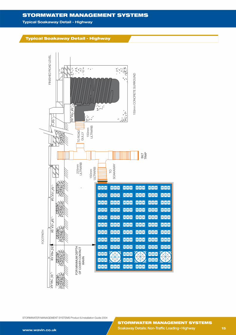
FOO
TPAT
H
150m
mU
LTR
AR
IB
150m
mU
LTR
AR
IB
TOS
OA
KA
WAY
TO R
OA
DG
ULL
Y
225m
mU
LTR
AR
IB
SIL
TTR
AP
FIN
ISH
ED
RO
AD
LE
VE
L
150m
m C
ON
CR
ETE
SU
RR
OU
ND
FOR
MIN
IMU
M D
EP
THO
F C
OV
ER
CO
NTA
CT
WA
VIN
Typical Soakaway Detail - Highway
CUSTOMER SERVICES 01249 766611
TECHNICAL ENQUIRIES01249 766655
TECHNICAL FAX 01249 766653
STORMWATER MANAGEMENT SYSTEMSTypical On-Line Water Storage Detail
16
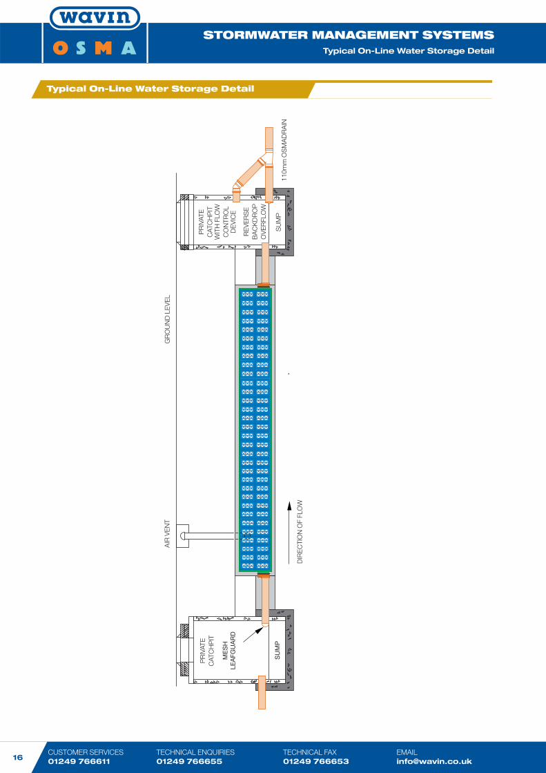
GR
OU
ND
LE
VE
L
PR
IVAT
EC
ATC
HP
IT
ME
SH
LEA
FGU
AR
D
SU
MP
AIR
VE
NT
RE
VE
RS
EB
AC
KD
RO
PO
VE
RFL
OW
PR
IVAT
EC
ATC
HP
ITW
ITH
FLO
WC
ON
TRO
LD
EV
ICE
SU
MP
110m
m O
SM
AD
RA
IN
DIR
EC
TIO
N O
F FL
OW
Typical On-Line Water Storage Detail
www.wavin.co.uk
STORMWATER MANAGEMENT SYSTEMSOn-Line Water Storage Detail ■ Off-Line Water Storage Detail
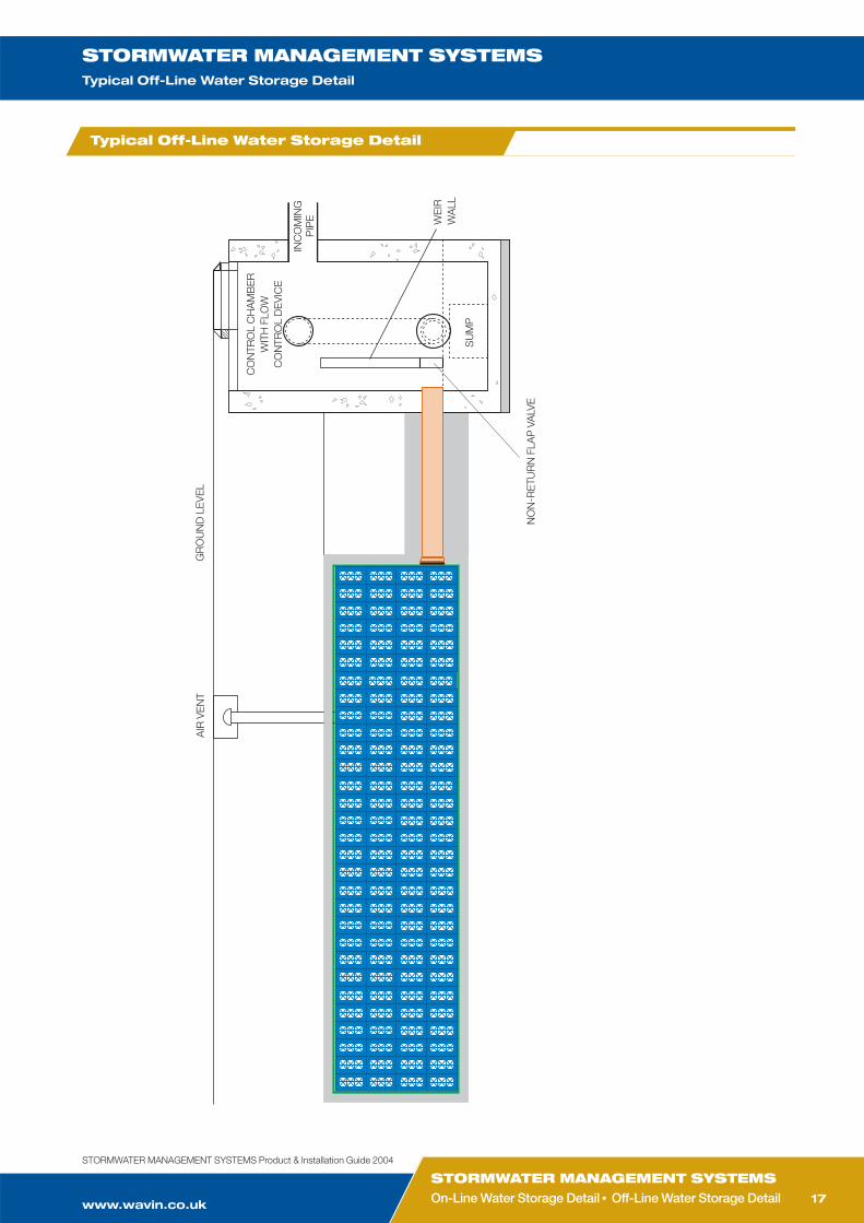
STORMWATER MANAGEMENT SYSTEMSTypical Off-Line Water Storage Detail
17
STORMWATER MANAGEMENT SYSTEMS Product & Installation Guide 2004
AIR
VE
NT
GR
OU
ND
LE
VE
L
CO
NTR
OL
CH
AM
BE
RW
ITH
FLO
WC
ON
TRO
L D
EV
ICE
INC
OM
ING
PIP
E WE
IRW
ALL
SU
MP
NO
N-R
ETU
RN
FLA
P V
ALV
E
Typical Off-Line Water Storage Detail
CUSTOMER SERVICES 01249 766611
TECHNICAL ENQUIRIES01249 766655
TECHNICAL FAX 01249 766653
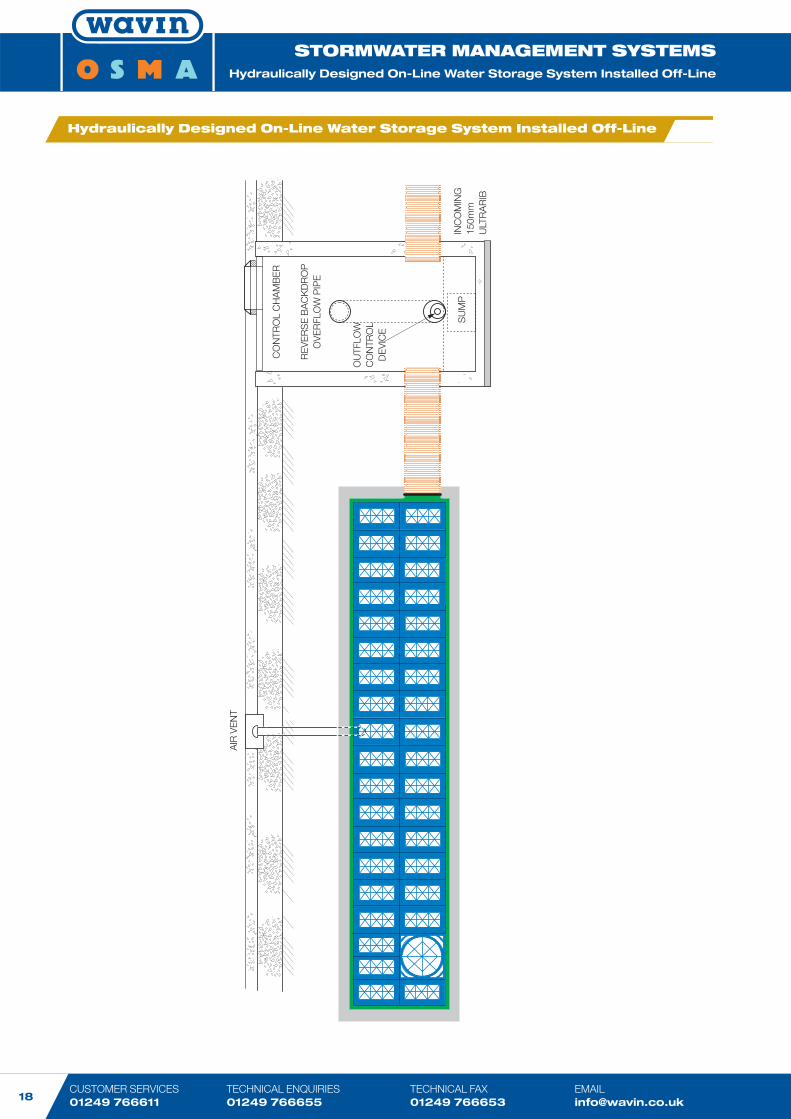
STORMWATER MANAGEMENT SYSTEMSHydraulically Designed On-Line Water Storage System Installed Off-Line
18
�
AIR
VE
NT
CO
NTR
OL
CH
AM
BE
R
RE
VE
RS
E B
AC
KD
RO
PO
VE
RFL
OW
PIP
E
OU
TFLO
WC
ON
TRO
LD
EV
ICE
SU
MP
INC
OM
ING
150m
mU
LTR
AR
IB
Hydraulically Designed On-Line Water Storage System Installed Off-Line
www.wavin.co.uk
STORMWATER MANAGEMENT SYSTEMSHydraulically Designed ■ Soakaway Detail with Silt Trap
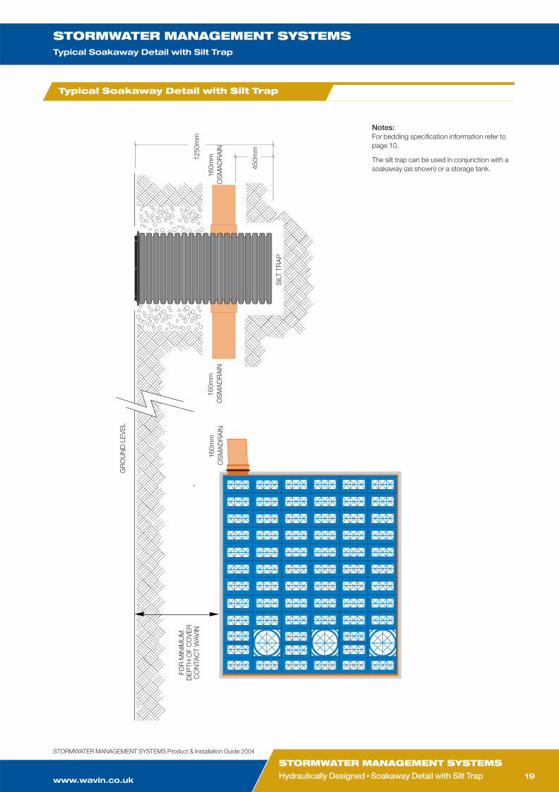
STORMWATER MANAGEMENT SYSTEMSTypical Soakaway Detail with Silt Trap
19
STORMWATER MANAGEMENT SYSTEMS Product & Installation Guide 2004
160m
mO
SM
AD
RA
IN
SIL
T TR
AP
FOR
MIN
IMU
MD
EP
TH O
F C
OV
ER
CO
NTA
CT
WAV
IN
450m
m
160m
mO
SM
AD
RA
IN16
0mm
OS
MA
DR
AIN
1250
mm
GR
OU
ND
LE
VE
LNotes:For bedding specification information refer topage 10.
The silt trap can be used in conjunction with asoakaway (as shown) or a storage tank.
Typical Soakaway Detail with Silt Trap

CUSTOMER SERVICES 01249 766611
TECHNICAL ENQUIRIES01249 766655
TECHNICAL FAX 01249 766653
STORMWATER MANAGEMENT SYSTEMSIntroduction to Garastor
20
Development of sites results in a large
proportion of area being covered by
impermeable surfaces such as roofs, car
parks and roads. Surface water run-off
therefore increases up to 80%. Building
Regulations and guidance now requires a
sustainable approach to development,
which minimises the effects of run-off to
that of a greenfield site (20%).
Developed in collaboration with Bryant
Homes, Garastor (polypropylene control
chamber) represents a house by house,
rather than a development wide
approach, to stormwater management.
Garastor controls the flow of water at
source by temporarily storing water under
a soft landscaped area using the AquaCell
system or in the void space under the
floor slab of a residential garage. It
eliminates the need for costly, space-
hungry, on-site communal water-storage
structures or ponds which enables better
use of developable land.
During high intensity rainfall, water from
the roof or hardstanding areas is diverted
via the Garastor control unit into the
storage void. As the storm subsides the
rainwater can be slowly released back
into the main drainage system.
Note:Garastor can be used as a flow control devicefor any AquaCell storage system, no greaterthan one unit deep with a discharge of up to 1.4l/s via the 30mm release flow orifice.
Introduction to Garastor ®*
Garastor – polypropylene control chamber
Internal view of Garastor
*Garastor is manufactured under licence (Patent Number GB2357093)
www.wavin.co.uk
STORMWATER MANAGEMENT SYSTEMSIntroduction to Garastor ■ Garastor System Overview
STORMWATER MANAGEMENT SYSTEMSGarastor System Overview
21
STORMWATER MANAGEMENT SYSTEMS Product & Installation Guide 2004
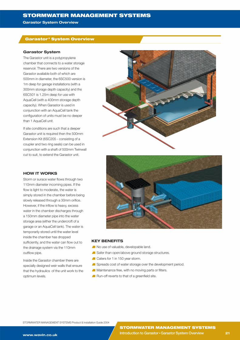
Garastor System
The Garastor unit is a polypropylene
chamber that connects to a water storage
reservoir. There are two versions of the
Garastor available both of which are
500mm in diameter, the 6SC500 version is
1m deep for garage installations (with a
300mm storage depth capacity) and the
6SC501 is 1.25m deep for use with
AquaCell (with a 400mm storage depth
capacity). When Garastor is used in
conjunction with an AquaCell tank the
configuration of units must be no deeper
than 1 AquaCell unit.
If site conditions are such that a deeper
Garastor unit is required then the 500mm
Extension Kit (6SC205 - consisting of a
coupler and two ring seals) can be used in
conjunction with a shaft of 500mm Twinwall
cut to suit, to extend the Garastor unit.
HOW IT WORKS
Storm or surace water flows through two
110mm diameter incoming pipes. If the
flow is light to moderate, the water is
simply stored in the chamber before being
slowly released through a 30mm orifice.
However, if the inflow is heavy, excess
water in the chamber discharges through
a 150mm diameter pipe into the water
storage area (either the undercroft of a
garage or an AquaCell tank). The water is
temporarily stored until the water level
inside the chamber has dropped
sufficiently, and the water can flow out to
the drainage system via the 110mm
outflow pipe.
Inside the Garastor chamber there are
specially designed weir walls that ensure
that the hydraulics of the unit work to the
optimum levels.
KEY BENEFITS
No use of valuable, developable land.
Safer than open/above ground storage structures.
Caters for 1 in 150 year storm.
Spreads cost of water storage over the development period.
Maintenance free, with no moving parts or filters.
Run-off reverts to that of a greenfield site.
Garastor ® System Overview
CUSTOMER SERVICES 01249 766611
TECHNICAL ENQUIRIES01249 766655
TECHNICAL FAX 01249 766653
STORMWATER MANAGEMENT SYSTEMSGarastor Principal Components
22
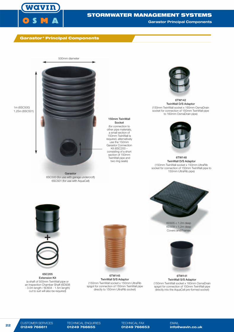
6SC205Extension Kit
(a shaft of 500mm TwinWall pipe oran Inspection Chamber Shaft (6D938- 3.0m length / 6D934 - 1.5m length)
cut to suit will also be required)
6D935 < 1.2m deep6D939 > 1.2m deepCovers and Frames
500mm diameter
1m (6SC500)1.25m (6SC501)
Garastor6SC500 (for use with garage undercroft)
6SC501 (for use with AquaCell)
6TW141TwinWall S/S Adaptor
(150mm TwinWall socket x 160mm OsmaDrainspigot for connection of 150mm TwinWall pipedirectly into the AquaCell pre-formed socket)
150mm TwinWall Socket
(for connection toother pipe materials,
a small section of150mm TwinWall is
required, alternativelyuse the 150mm
Garastor ConnectionKit (6SC200 –
consisting of a shortsection of 150mmTwinWall pipe and
two ring seals)
6TW142TwinWall D/S Adaptor
(150mm TwinWall socket x 160mm OsmaDrainsocket for connection of 150mm TwinWall pipe
to 160mm OsmaDrain pipe)
6TW145TwinWall S/S Adaptor
(150mm TwinWall socket x 150mm UltraRibspigot for connection of 150mm TwinWall pipe
directly to 150mm UltraRib socket)
6TW148TwinWall D/S Adaptor
(150mm TwinWall socket x 150mm UltraRibsocket for connection of 150mm TwinWall pipe to
150mm UltraRib pipe)
+
Garastor ® Principal Components
www.wavin.co.uk
STORMWATER MANAGEMENT SYSTEMSGarastor Principal Components ■ Garastor Installation Methods
STORMWATER MANAGEMENT SYSTEMSTypical Garastor Installation Methods
23
STORMWATER MANAGEMENT SYSTEMS Product & Installation Guide 2004
1. Place the Garastor Unit (6SC500 or
6SC501) on a minimum of 100mm
“as-dug” or granular material. Ensure
that the unit is as close to the garage
undercroft or AquaCell structure as
possible and in a suitable position to
allow pipework connection.
Note: It is important to ensure that the chamber isplaced in a level position and that the invert ofthe 150mm pipe connection is level with thebase of the concrete undercroft or the base ofthe AquaCell units.
2. Connect pipework in accordance with
standard pipe installation guidelines.
3. Surround the Garastor unit with
150mm of similar material to that used
for the bedding.
4. Fit relevant cover and frame according
to depth of unit: Up to and
including1.2m deep 6D935 Deeper
than 1.2m6D939
Note: When surounded by a concrete plinth (150mmx 150mm) the cover can be used in situationswith a loading of upto 30Kn (3 tonnes) i.e.domestic driveways.
5. Adequate ventilation must be
provided:
- to the garage undercroft using
either air bricks or rainwater
downpipes connected directly into
the storage area.
- to the AquaCell structure using an
air vent (NB. One air vent is
required per 7,500 square metres
of impermeable area to be
drained).
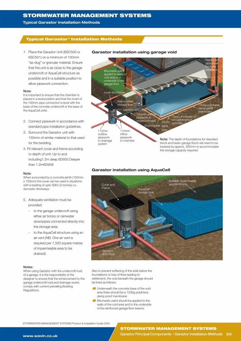
Garastor installation using garage void
Bitumastic paintapplied to walls ofvoid area andunderside of thegarage floor
cover and frame
Wall to retainstorage area
Stored water
75mm thickness ofsmooth finishedconcrete
1200g polythenedamp proofmembrane
50mm sandlayer
Rainwaterpipe (or airbrick) forventilation
Note: The depth of foundations for standardblock and beam garage floors will need to belowered by approx. 300mm to accommodatethe storage capacity required.
150mm outflow pipework toundercroft/void
110mminflowpipeworkto chamber
110mmoutflowpipeworkto drainagesystem
Notes:When using Garastor with the undercroft/voidof a garage, it is the responsibility of thedesigner to ensure that the enhancement to thegarage undercroft/void and drainage workscomply with current prevailing BuildingRegulations.
Also to prevent softening of the soils below thefoundations or loss of fines leading tosettlement, the void beneath the garage shouldbe lined as follows:
Underneath the concrete base of the voidarea there should be a 1200g polythenedamp proof membraneBitumastic paint should be applied to thewalls of the void area and to the undersideof the reinforced garage floor beams.
Garastor installation using AquaCell
Cover andFrame AquaCell
storage tank
Suitable impermeablegeomembrane
Garastor(6SC501)
Garastor (6SC500)
Typical Garastor ® Installation Methods

CUSTOMER SERVICES 01249 766611
TECHNICAL ENQUIRIES01249 766655
TECHNICAL FAX 01249 766653
STORMWATER MANAGEMENT SYSTEMSCase studies
24
Case studies
The sky’s the limit for WavinPlastics
THE CLIENT:
Birmingham Airport
THE PROBLEM:
To prevent flooding on a new long-stay
car park covered with paving, and help
the Airport to comply with its policy of
sustainable development.
THE SOLUTION:
Over 7,000 AquaCell infiltration modules
were installed on the site providing a
robust and long life infiltration base. A
permeable geotextile was the only other
component required to complete the
installations.
THE QUOTE:
“Wavin’s solution to stormwater
management combines practical and
operational benefits over the alternative
methods available to the developer. Its
system proved to be economically and
functionally favourable whilst providing
storage of over 1,300 cubic metres of
surface water run-off.”
AquaCell passes toughesttests during worst stormsfor 50 years
THE CLIENT:
Ilchester Cheese Company
THE PROBLEM:
Controlling flooding/water on a regularly
flooded area.
THE SOLUTION:
In order to control stormwater at the
Ilchester site, a system which comprised
of 1,352 AquaCell units was installed to
limit the outflow and provide temporary
storage.
THE QUOTE:
“What we have seen at the Cheese
Company over the past fortnight is
evidence of a highly successful system.
The surrounding area is completely
waterlogged with the river only half a mile
down the road. Our site is bone dry - any
risk of damaged land has been alleviated”.
Weathering the storm onBrownfield Land
THE CLIENT:
Graham & Brown Wallcovering
THE PROBLEM:
How to manage/control storm or flood
water on a low lying brownfield site,
adjacent to a river with a history of
flooding, and prevent the leaching of
contaminants into the high water table
from the site which used to be a power
station.
THE SOLUTION:
To collect stormwater from the
development in a trench surrounding the
new factory filled with 2,000 Wavin
AquaCell units clipped together,
encapsulated in a robust fully welded
hydrocarbon resistant geomembrane,
which in turn was wrapped in a non-
woven needle-punched geotextile.
THE QUOTE:
“The 95% void capacity of Wavin’s system
was a key factor for us. The original
proposal for the site was based on
installing stone-filled trenches with a
maximum void capacity of 30%.”

www.wavin.co.uk
STORMWATER MANAGEMENT SYSTEMSCase studies ■ Notes
STORMWATER MANAGEMENT SYSTEMSNotes
25
STORMWATER MANAGEMENT SYSTEMS Product & Installation Guide 2004

CUSTOMER SERVICES 01249 766611
TECHNICAL ENQUIRIES01249 766655
TECHNICAL FAX 01249 766653
STORMWATER MANAGEMENT SYSTEMSNotes
26

www.wavin.co.uk
STORMWATER MANAGEMENT SYSTEMSNotes n Technical n Further Information
STORMWATER MANAGEMENT SYSTEMSTechnical Assistance n Further Information
27
Contents
WAVIN ONLINEThe complete OSMA product catalogue, together with design and
installation guidance, is also available online at: www.wavin.co.uk
All literature can be downloaded via the searchable PDF library at
www.wavinpdfs.co.uk
Wavin images can be downloaded at different resolutions from
www.wavinimages.co.uk
OSMA Stormwater Management systems
are backed by Wavin’s comprehensive
technical advisory service. This is available
to provide expert assistance at every stage
of a project, from planning and product
selection to installation and maintenance.
Services include:
Full technical literature, including:
- System Product Guides
- Design and Installation Guides
- Trade Price Lists
Contact Wavin Technical Design
Department for prompt assistance:
TECHNICAL DESIGNTel: 01249 766655Fax: 01249 766653Email: [email protected]
To request a copy of any item(s) of current
literature, please contact:
LITERATURE REQUESTSTel: 01249 766333Fax: 01249 766332Email: [email protected]
Technical Adviceand Assistance Further Information
STORMWATER MANAGEMENT SYSTEMSThe following related publications are available for OSMA
Stormwater Management systems:
Design and Installation Manual
Trade Price List
ASSOCIATED OSMA SYSTEMSOSMA systems are fully integrated to provide a total
solution for above and below ground drainage,
plumbing and heating. Contact Wavin Technical
Design Department for further details regarding:
OSMA Rainwater systems
OSMA Soil & Waste systems
OSMA Flexible Plumbing systems
OSMA Underfloor Heating systems
OSMA Below Ground Drainage
systems
OSMA Water Management
systems
OSMA Ducting systems
OSMA Pressure Pipes for
Water
OSMA Pressure Pipes for
Gas
STORMWATER MANAGEMENT SYSTEMS Product & Installation Guide 2004

Wavin Plastics LimitedParsonage Way Chippenham Wiltshire SN15 5PN
Tel: 01249 766600Fax: 01249 443286
Email: [email protected]
All OSMA systems are backed by fulltechnical literature and project support.See inside back cover for details.
Wavin Plastics Limited operates a programme of continuous product development, and therefore reserves the right to modify or amend the specification of their products without notice. All information in this publication is given ingood faith, and believed to be correct at the time of going to press. However, no responsibility can be accepted forany errors, omissions or incorrect assumptions. Users should satisfy themselves that products are suitable for thepurpose and application intended.
ISO 9001:2000
AquaCell® & Garastor® StormwaterManagement Systems
Product andInstallation Guide
Meeting your needsOSMA Water Management systems, developed by WavinPlastics Limited, form part of a comprehensive range of plasticsystems to provide intelligent solutions for all building, constructionand utilities projects.
These include:
Above Ground ProjectsOSMA Rainwater systems
OSMA Soil & Waste systems
Plumbing & Heating ProjectsOSMA Flexible Plumbing systems
OSMA Underfloor Heating systems
Below Ground ProjectsOSMA Below Ground Drainage systems
OSMA Water Management systems
OSMA Ducting systems
Pressure Pipe ProjectsOSMA Pressure Pipes for Water
OSMA Pressure Pipes for Gas
www.wavin.co.uk
WM
417