railway signalling - novaris · railway signalling is a specialist field containing many types of...
TRANSCRIPT

Railway Signalling
Surge protection for railway systems
Robert Jordan

Novaris Pty Ltd 33 061 301 88 novaris.com.au [email protected]
Page 1 Document No: 0015-D63V1
72 Browns Rd, Kingston TAS, AUSTRALIA 7050
Tel +613 6229 7233 Fax +613 6229 9245
Contents
Introduction ............................................................................................................................................ 2
Safety ...................................................................................................................................................... 2
Surge Protection Components ................................................................................................................ 3
Protection Modes ................................................................................................................................... 4
Earthing and Bonding .............................................................................................................................. 4
Let-through Voltage ................................................................................................................................ 7
Power supply protection ......................................................................................................................... 7
Surge Diverters........................................................................................................................... 8
Surge Filters ............................................................................................................................. 10
Advantages of Surge Filters ..................................................................................................... 11
Effect of shunt-connected leads .............................................................................................. 11
AC power ............................................................................................................................................... 12
DC power............................................................................................................................................... 13
Track Circuit Protection ........................................................................................................................ 13
Signal lighting circuits ........................................................................................................................... 14
Points drive circuits ............................................................................................................................... 15
Points detection circuits ....................................................................................................................... 16
Axle counters ........................................................................................................................................ 17
Miscellaneous input and output circuits .............................................................................................. 18
Line circuits ........................................................................................................................................... 18
Wiring for best performance ................................................................................................................ 19
Basic rules for signalling surge protection ............................................................................................ 20
Other railway applications .................................................................................................................... 20
Bibliography .......................................................................................................................................... 21

Novaris Pty Ltd 33 061 301 88 novaris.com.au [email protected]
Page 2 Document No: 0015-D63V1
72 Browns Rd, Kingston TAS, AUSTRALIA 7050
Tel +613 6229 7233 Fax +613 6229 9245
Introduction
Railway signalling is a specialist field containing many types of electrical circuits, many of which are rated to the highest level of functional safety, SIL-4, “Fail Safe” or “Vital” in the traditional railway signalling parlance. Different manufacturers use different electrical systems for power supplies and signalling circuits as well as many special protocols and communications systems for their specific railway systems. Applying electrical surge protection to these systems can be a challenge and must consider three basic points:
1. Will the surge protection device (SPD) impact the safety rating of the circuit, even under failure conditions of the SPD?
2. Will the SPD provide the desired level of protection to the circuit and its connected elements? 3. What voltages and currents will the SPD be exposed too, including standing and fault voltages
caused by other electrical systems such as traction and power supply systems?
Safety
Signalling circuits of the traditional types are safety circuits, such as:
• AC Power distribution
• DC power
• Track circuits
• Signal lighting circuits
• Points drive circuits
• Point detection circuits
• Axle counters
• Miscellaneous Inputs and Outputs
• Line circuits
Safety is implicit in maintaining correct isolation of the individual circuits from each other and from earth faults. It is common in railway signalling to use floating circuits (IT type) even for AC power supply distribution and the use of Earth Leakage Detectors (ELD) is widespread to ensure any faults to earth are detected. What can cause safety issues to all these types of circuits is what is known as an “Un-revealed Fault to Earth”. As the fault is un-revealed it is probably not detected, the fault can persist for many years, even decades. The safety problems then come if a second fault to earth occurs on the same or even a different circuit, this may also be un-revealed. The two faults to earth together can then provide an electrical path between one circuit and another via the earth, potentially causing the wrong control signals to be displayed, locking released or other unsafe conditions such as a track circuit not detecting a train.

Novaris Pty Ltd 33 061 301 88 novaris.com.au [email protected]
Page 3 Document No: 0015-D63V1
72 Browns Rd, Kingston TAS, AUSTRALIA 7050
Tel +613 6229 7233 Fax +613 6229 9245
The signalling system itself mitigates the effect of these types of unsafe failures by using techniques such as ELD’s, double cutting of external circuits and sequenced release of locking etc. When electrical surge protection is applied to these circuits there will be additional connection paths to earth introduced for passing the surge energy to ground and so these need to be considered carefully as they can impact the safety of the circuit by introducing additional un-revealed earth connections when/if they suffer an internal failure.
Surge Protection Components
There are three families of components that are used to manufacture electrical surge protection devices:
Type 1. Voltage switching devices such as spark gaps and gas discharge tubes (GDT). Type 2. Voltage limiting devices such as metal oxide varistors (MOV) and semiconductor
avalanche devices, often referred to as transzorbs. Type 3. Specialist devices designed to open circuit small loads such as the Iswitch device.
For most signalling applications the type 1 and type 2 devices are used in combination with coordinating impedances to provide effective protection to all equipment including sensitive electronic control equipment such as computer based interlockings. In selecting the components for safety related circuit protection, the failure modes of the components themselves must be understood and considered in relation to avoiding un-revealed earth connection faults discussed in the section above. Type 1 devices generally appear in circuit as an open circuit. They consist of two or three electrodes encased in a ceramic tube that are separated by an insulating medium, air in the case of a spark gap or special ionising gases in the case of a GDT. On application of a voltage above their trigger point all the electrodes within the device short circuit together passing the surge energy to ground. They then become open circuit after the surge current has passed. However, this is not always the case. If the device takes a surge at or above its maximum ratings, it can be left damaged with one of more of the internal electrodes shorted together by actual melting of the metallic electrodes (usually an alloy of copper and other metals). If this internal short is between one line and the earth electrode we have produced and un-revealed earth fault which is highly undesirable. Novaris has developed special techniques to ensure that in the event of this type of fault caused by excessive surge currents the device is safely disconnected from the earth connection and provided with an indicator such that not only is the failure mode prevented it is also revealed. (visual and/or electrical alarm). Novaris is the only surge protection manufacturer that uses such safety devices. Type 2 devices have failure modes that are short circuit even if they do not have their surge ratings exceeded. They are manufactured in such a way that random failure modes will almost always lead to a short circuit failure, at least initially.

Novaris Pty Ltd 33 061 301 88 novaris.com.au [email protected]
Page 4 Document No: 0015-D63V1
72 Browns Rd, Kingston TAS, AUSTRALIA 7050
Tel +613 6229 7233 Fax +613 6229 9245
For this reason, Novaris does not use these devices for safety related surge protectors in any connection paths to earth unless they are protected by a type 1 device in the same path. Type 2 devices are mostly used for protection in the transverse mode (line to line) where a short circuit fault will lead to the loss of the signal in the circuit and probably the rupture of a fuse or circuit breaker leading to a safe and revealed failure. Type 3 devices are highly specialised integrated circuits and specific in application. Novaris does not use any in their range of railway signalling protectors.
Protection Modes
Electrical surges can present themselves at equipment in one of two ways:
• Transverse Mode, when individual conductors in a circuit rise in voltage relative to another. This is commonly seen on paired circuits where one line rises relative to another causing damage to the controlling equipment on one individual circuit - a CBI or PLC input for example.
• Common Mode, when all, or a group, of conductors in a circuit rise in voltage relative to a common point, most often a chassis, ground point or earth connection. This is commonly seen where circuits coming from outdoors all have a common mode voltage that exceeds the break-down or insulation voltage of a piece of connected equipment and a component break down occurs often destroying the whole piece of equipment. Common mode faults cause more than 90% of damage seen to signalling equipment and are the hardest to protect against as the selection of components is limited by the safety concerns detailed above.
Earthing and Bonding
This is an important area particularly when considering protection against common mode surges which cause almost all the damage to signalling equipment. Earthing. Contrary to popular belief and what is written in many specifications the actual resistance of the earth connection or system is completely unimportant to the successful application of electrical surge protection. To explain why the following calculation is considered: Assume we have a very good building earth resistance measured as 1.0 ohm. This is extremely difficult to achieve in practice and more common values seen in railways might be 10-100 ohms. If we take a fairly modest common mode induced surge delivering an 8/20µs short circuit current through a surge protector of 8kA (8000 Amps peak) then using Ohms law, we get:
Earth potential rise = I x R 8000A x 1.0Ω = 8000 volts
This means the location cabinet or signal building will rise to a peak of 8000 volts above earth. If we then take a more realistic earth resistance of 10 Ohms we will get a rise of 8000 x 10 = 80,000 volts.

Novaris Pty Ltd 33 061 301 88 novaris.com.au [email protected]
Page 5 Document No: 0015-D63V1
72 Browns Rd, Kingston TAS, AUSTRALIA 7050
Tel +613 6229 7233 Fax +613 6229 9245
Clearly with either of these voltages if we have equipment in the location or room that has circuits coming from outside where the earth potential is much closer to zero then the weakest piece of equipment in the location will be easily destroyed. Most specialist signalling equipment is only rated for isolation to chassis at 2500 – 3500 volts and commercial equipment much less, typically only 1500 volts. Bonding. To make matters worse we must consider the inductance of all the electrical elements in the earth path and these effects are much greater than the resistive effects as the effective frequency of current surges is very high.
Figure 1. Inductive effects of 1m conductors
Figure 1 shows the results of tests completed in the Novaris laboratory and records the voltage generated across 1.0 metre lengths of various wires and conductors when an 8/20µs current of 9000 amps peak is passed. The red trace is the current through the conductor and the other colours show the voltage recorded end to end of the 1.0 metre lengths of different cross sections. As can be seen, using a typical earth wire of 6mm² (blue trace), we are producing a voltage drop of 1600 volts for every metre of wire. In a typical signalling installation, the earth wire of a surge protection device will be a minimum of 2 metres in length, so we already have 3200 volts being applied to our “protected” equipment even before we add the let through voltage of the SPD itself. Clearly this is already at a voltage level that will break down all commercial equipment and probably some specialised signalling equipment as well.
For 1.0 metre of conductor
1600 volts

Novaris Pty Ltd 33 061 301 88 novaris.com.au [email protected]
Page 6 Document No: 0015-D63V1
72 Browns Rd, Kingston TAS, AUSTRALIA 7050
Tel +613 6229 7233 Fax +613 6229 9245
There is no way to avoid these effects. Even the large busbar conductors are still producing around 1000 volts per metre and this is mostly due to the inductance associated with any conductive object. In fact, the effect of inductance produces about 500 times more voltage than that of resistance and these voltages are added to the let-through voltage of the SPD that is read from the data sheet. This effect is usually ignored or unknown by signalling designers. The only way these effects can be mitigated is by using equipotential bonding and this is the most critical aspect of applying surge protection such that it protects against the damaging common mode effects mentioned. Equipotential bonding is the use of bonding conductors within the equipment itself such that the items of equipment to be protected are maintained at voltages to one and other that are below the levels that will cause damage. To do this means understanding where current will flow when the surge protection device operates, recognising the large voltages that the surge protector will rise to due to inductive effects and then arranging the bonding such that the equipment being protected is bonded to the SPD earth terminal and not to a separate earth bar that is at a different and much lower potential. Doing this means the equipment and the surge protector stay at approximately the same voltage as each other, but the whole bonded assembly will rise to whatever voltage the current and the earth path inductance produces. The key is that voltages within the equipment are kept to safe levels.
Figure 2 Example of termination rack bonding
Wiring and connections to TCP-2.5-40-230
Line/cable/dirty Side
Terminals L1 and L2
Equipment/Tx/Rx/
clean side
Terminals E5 and E6
L1L1L1
L2
E5
E6
Alarm indication
contact terminals 3
and 7
Earthing direct via the
DIN mounting rail Bond the DIN rails together with
earth bus bars to form a matrix,
minimum three, top, middle and
bottom. Make the main earth cable
connection in the center

Novaris Pty Ltd 33 061 301 88 novaris.com.au [email protected]
Page 7 Document No: 0015-D63V1
72 Browns Rd, Kingston TAS, AUSTRALIA 7050
Tel +613 6229 7233 Fax +613 6229 9245
Figure 2 shows the correct method of bonding a wall termination rack containing SPDs so that equipment common mode voltages are kept to a minimum. Bonding all the DIN or G rails together with three bus bars as above provides a low impedance bonded frame and then the earth cables coming from all other racks, cubicles or signalling equipment can be bonded to the centre bar of the array, producing minimum voltage differences between the circuit conductors and the ground or chassis of the equipment to which they run. The main incoming earth cable from the earthing system should ideally be connected to the centre connection of this array using a large bolt and keeping the cable as short and straight as possible. Note: If standards and regulation specify a green and yellow earth wire be fitted, all Novaris SPDs are provided with additional terminals for this, but to ensure best performance the SPDs must be mounted on DIN or G rails and these used as the primary earth connection bonded as recommended above. The surge current flow will always take the path of lowest impedance and this will always be via the mounting rails and their bonding.
Let-through Voltage
One of the key differentiating factors when selecting surge protection devices is their let through voltage or protection level. The Australian Standard on Lightning Protection (AS1768) defines a standard combination waveform consisting of a 1.2/50us 6kV peak combined with an 8/20us 3kA peak. The let through voltage is the residual voltage exposed to the load past the SPD. To get a better understanding of the let through voltages associated with higher energy surges, 1.2/50us 20kV, 8/20us 10kA surges are also used by Novaris. For devices containing GDTs Novaris has a special 10/700µS generator that produces a voltage rise of 1000V/µS. This is used in the evaluation of the firing voltage of different GDTs and Novaris always selects the fastest acting devices that can support the desired surge current. We have found that identically specified GDTs can have real world firing voltages that vary by as much as 300 volts, so selecting the best devices cannot be done without this specialist test equipment. With experience gained over decades that if electrical control circuits can be protected to withstand 8/20µs surges of 8kA or 8000 Amps peak at the surge protector then then they will have a trouble-free life with no damage even in severe lightning areas like Northern Territory, Indonesia and Malaysia. 8kA is chosen because circuit and cable impedances prevent much higher currents than this from flowing in typical small signal cables. Power supply cables can transmit much larger currents and so require higher protection levels.
Power supply protection
In railway signalling, power distribution to remote equipment is usually accomplished with a fully floating supply so that earth leakage detection can be provided. In IEC terms this network is referred to as IT where the equipment is earthed locally and there is no common earth/neutral conductor between the equipment and the point of generation.

Novaris Pty Ltd 33 061 301 88 novaris.com.au [email protected]
Page 8 Document No: 0015-D63V1
72 Browns Rd, Kingston TAS, AUSTRALIA 7050
Tel +613 6229 7233 Fax +613 6229 9245
This has the advantage of reduced conduction of interference from other sources and has always been popular for special applications like railway signalling. These can be single phase or three phase and at various voltages depending on the country and rail authority. Single phase voltages are often higher than normal standards and 650 and 1000 volts are common. In selecting appropriate surge protection for these IT systems, the insulation level and test voltage of the feed and step-down isolation transformers needs to be considered. The surge protection must keep the common mode voltage levels well below the rated breakdown voltage of these transformers. For effective protection of these floating supplies, protection needs to be provided between phases and from phases to ground. Novaris refers to this as “All Mode Protection” and the data sheets will note this where applicable. If the distribution system is a standard 3 phase star connection with a common neutral Novaris also has suitable protection; please refer to the data sheets. Power supply protection can be provided by two main types of equipment:
1. Surge Filter 2. Surge Diverter
The performance of the two devices are very different and to understand this the concept of “let through voltage” is used. This is the voltage that the equipment being protected will be exposed to for a given surge coming from the exposed or line side of the distribution system. Lower let through voltages provide better protection for more sensitive equipment. Some surge protection manufacturers use lower voltage components to achieve a lower voltage let through at the expense of reliability. Novaris uses 275V MOVs for their 240V products to provide adequate headroom for tolerable voltage fluctuations. If lower let through voltages are required Novaris can provide a range of surge filters that offer excellent performance without sacrificing reliability.
Surge Diverters
Surge diverters are connected in parallel. They consist of surge arresting components, usually metal oxide varistors (MOVs) and gas arresters. They work by diverting surge energy to ground. A typical let-through voltage waveform for a surge diverter is shown in Figure 3 below:

Novaris Pty Ltd 33 061 301 88 novaris.com.au [email protected]
Page 9 Document No: 0015-D63V1
72 Browns Rd, Kingston TAS, AUSTRALIA 7050
Tel +613 6229 7233 Fax +613 6229 9245
Figure 3. Typical let-through voltage of a surge diverter (6kV/3kA)
The let-through voltage shown here is just under 700V. Whilst this is low enough to protect most equipment, more sensitive electronic equipment would still be damaged by a surge of this magnitude. Surge diverters that employ other components such as Silicon Avalanche Diodes (SADs) can have lower let-through voltages (as low as 600V). However, this is generally at the expense of the reliability and lifetime of the surge diverter.
Figure 4. Typical let-through of a surge diverter (20kV/9kA)
As can be seen in Figure 4, the scaling for let through voltage is not linear based on the current applied. With a maximum surge current three times larger than the one defined in AS1768, at 9kA the let through voltage rises to just over 800V.

Novaris Pty Ltd 33 061 301 88 novaris.com.au [email protected]
Page 10 Document No: 0015-D63V1
72 Browns Rd, Kingston TAS, AUSTRALIA 7050
Tel +613 6229 7233 Fax +613 6229 9245
Surge Filters
Surge filters are series connected. They employ three-stage protection consisting of surge diverters at the input and output, and a low-pass LC filter in between. The low pass filter not only suppresses surges, but also provides some filtering against harmonic noise. In the event of a surge, the majority of the surge energy is diverted to ground by the stage 1 surge diverter. As a result, the voltage at the input to stage 2 is clamped.
Figure 5. Surge filter configuration
The low-pass filter offers a low impedance at the signal frequency applied. This allows 50-60Hz power to pass through whilst heavily attenuating the high frequency surge and higher harmonics. This leaves only a small surge for the stage 3 surge diverter to deal with. Typical values would be a 900V let-through voltage for stage 1 and a 600V drop across stage 2. This leaves only 300V (900 – 600 = 300) at the output of the filter. Let-through voltages this low will protect even the most sensitive of electronic equipment. A typical let-through voltage waveform for a surge filter is shown in Figure 6 below:
Figure 6.Typical let-through voltage of a surge filter (6kV/3kA)

Novaris Pty Ltd 33 061 301 88 novaris.com.au [email protected]
Page 11 Document No: 0015-D63V1
72 Browns Rd, Kingston TAS, AUSTRALIA 7050
Tel +613 6229 7233 Fax +613 6229 9245
With the 20kV / 9kA waveform in Figure 7 we can again see the non-linear characteristics of the MOVs. With three times the current the let through voltage has only increased by 170V.
Figure 7. Typical let-through voltage of a surge filter (20kV/9kA)
Advantages of Surge Filters
Besides the fact that surge filters have a remarkably lower let-through voltage, they have other advantages over surge diverters as discussed below.
Effect of shunt-connected leads
Because surge diverters are connected in parallel, the let-through voltage experienced by the connected equipment depends not only upon the performance of the surge diverter, but also on the inductance of the connecting leads. Figure 8 illustrates this principle:
Figure 8. Effect of shunt-connected leads
Even if the inductance of the connecting leads is low, the extremely fast rise time of a lightning induced surge will create a very large voltage across them. Figure 9 (below) shows the let-through voltage of a surge diverter measured at its terminals, with 1m of connecting leads and with 2m of connecting leads.

Novaris Pty Ltd 33 061 301 88 novaris.com.au [email protected]
Page 12 Document No: 0015-D63V1
72 Browns Rd, Kingston TAS, AUSTRALIA 7050
Tel +613 6229 7233 Fax +613 6229 9245
The total length of connecting leads includes the length from the main feed, through the disconnector to the line terminal, and from the neutral terminal back to the incoming feed.
Figure 9. Let-through voltage of a surge diverter with and without connecting leads
This shows that in a practical situation, the actual let-through voltage experienced by connected equipment can be much greater than that stated in the technical specifications for the surge diverter. A larger surge current causes a faster rise time which in turn increases the let through voltage due to wire inductance. This problem is not experienced with surge filters because they are connected in series. The manufacturer establishes the length of all shunt-connected leads within the filter.This means:
• The filter can be designed to minimise the lengths of connecting leads, therefore minimising its let-through voltage.
• The performance of the filter is not installation dependant.
• The let-through voltage experienced by connected equipment in practical situations is always the same as that stated in the technical specifications for the filter.
AC power
Surge filters provide superior protection against lightning induced surges on mains power lines. Unlike surge diverters, their performance is not installation dependant. On top of these points, they reduce harmonic content and other noise, have a longer lifespan and are more reliable than surge diverters. Novaris always recommends a surge filter be used at each end of a power distribution cable if it is outdoors and more than 10m long. This will ensure all the connected equipment will have superior protection from all surges and harmonic effects.

Novaris Pty Ltd 33 061 301 88 novaris.com.au [email protected]
Page 13 Document No: 0015-D63V1
72 Browns Rd, Kingston TAS, AUSTRALIA 7050
Tel +613 6229 7233 Fax +613 6229 9245
The table below details products for AC power protection.
Device Type Novaris Part Number Comment
2 pole 63 Amp Surge Filter SF2-63-100-275-M 100kA rated
2 pole 10 Amp Surge Filter SFD2-10-100-130-A 100kA rated
2 pole 10 Amp Surge Filter SFD2-10-100-275-A 100kA rated
2 pole 10 Amp Surge Filter SFD2-10-100-460-A 100kA rated
DC power
DC power is not particularly common in railway signalling for external power distribution, but it is used in some countries. DC power limits the types of protection components that can be used. GDTs cannot be used directly as they will not turn off after the surge and can cause supply fuses to be ruptured by the follow-on DC power current that will continue to flow. This limits the components to type 2 devices, or a combination (hybrid) of the two, and thus surge filters are still the best option for sensitive electronics. Alternatively, if the installation wiring can be engineered correctly to minimise the let through voltage then a diverter can be effective. Novaris manufactures a full range of such devices in many voltage and packaging variants. Novaris makes specific DC PV protectors for large photovoltaic schemes with DC voltages of 1000 and 1500 volts. The table below details products for DC power protection.
Device Type Novaris Part Number Comment
Diverter 12V SDD2-12-14 LV Solar applications
Diverter 24V SDD2-12-30 LV Solar applications
Diverter 48V SDD2-40-50 LV Solar applications
Diverter 110V SDD2-40-130 LV Solar applications
Diverter 1000V SDPV-40-1000 MV Solar applications
Diverter 1500V SDPV-50-1500 MV Solar applications
Track Circuit Protection
There is a variety of track circuits still manufactured to this day. They can be grouped in the following general categories:
1. DC track circuits with insulated rail joints (IRJ) 2. Low frequency AC track circuits with insulated rail joints (IRJ) 3. Low audio frequency track circuits for main line applications, often jointless 4. High audio frequency track circuits for metro applications, usually jointless 5. High voltage impulse track circuits with insulated rail joints (IRJ)

Novaris Pty Ltd 33 061 301 88 novaris.com.au [email protected]
Page 14 Document No: 0015-D63V1
72 Browns Rd, Kingston TAS, AUSTRALIA 7050
Tel +613 6229 7233 Fax +613 6229 9245
6. Complex high audio frequency track circuits with multiple receivers, centre fed and fully jointless applications
Categories 1, 2 and 5 generally work at low impedances with surge protection connected either directly across the rails or at a trackside terminal box. The other categories involve more complicated electronics including microprocessors and work at higher impedances with tuning or matching units to convert the impedance to low levels at the trackside. These systems have surge protection provided at a trackside disconnection box and at the cable entry to signalling rooms or location cabinets where the sensitive electronic modules are housed. Where the safety integrity level of circuits is SIL-4 fail-safe surge protection must be used in all cases. In the selection of suitable surge protection for these circuits the levels of standing or induced voltages also must be considered. In electrified railways devices connected to the rails will be exposed to the traction return current and voltage. Long feed cables for audio frequency track circuits will be exposed to induction. The clamping or trigger voltage of the SPD must be chosen to be just above the maximum level of these induced voltages but not so high as to offer no protection to the track circuit equipment itself. There may also be specification requirements for levels of standing AC and DC voltages that the device must be subjected to whilst conducting a surge to ground. Novaris can test these scenarios at their laboratory. Novaris manufactures a range of SPDs to suit most common track circuits for both high and low risk areas. Novaris can also design and manufacture units to suit specific designs of track circuit. Contact Novaris directly for details. The table below details products for track circuit protection.
Device Type Novaris Part Number Comment
Single Track Side High kA GDT-H1-100-350-RPU For high exposure
Double Track Side High kA GDT-H2-100-350-RPU For high exposure
Replacement GDT GDT-100-350-RPU For high exposure
Single Track High kA Location Cabinet
ECD2-100-230 For high exposure
Single Track High kA Location Cabinet + Equaliser
TCP2-350-XXX For high exposure
Single Track 230V TCP-2.5-40-230 Failsafe with alarm
Single Track 350V TCP-2.5-40-350 Failsafe with alarm
Signal lighting circuits
These circuits are usually AC powered either directly from specific lamp driver cards for modern interlockings or via signalling safety relays for older generations of interlocking.

Novaris Pty Ltd 33 061 301 88 novaris.com.au [email protected]
Page 15 Document No: 0015-D63V1
72 Browns Rd, Kingston TAS, AUSTRALIA 7050
Tel +613 6229 7233 Fax +613 6229 9245
Generally, the signal light is a module containing an electronic power supply driving an array of LEDs contained in a plastic housing. The plastic housing normally provides over 4000 volts of isolation from common mode effects between the driving circuit and the main metallic body of the signal head housing. This is usually adequate to avoid common mode flashover inside the LED module and transverse mode protection is usually provided internally using one or more MOVs mounted on the power supply circuit board. If this proves to be inadequate a specific SPD can be installed in the signal head with the ground connection bonded directly to the metallic signal head itself. At the other end of the circuit where the drive voltages are switched an SPD is required for locations that are exposed or have a high incidence of lightning. It is almost always a common mode effect induced into the trackside cabling that causes the damage so, the installation and bonding of the surge protector is critical. Novaris has a range of fail-safe SPDs for these applications with our range of Module Protection Units (MPU) and our SL2 range of paired protectors. The table below details products for signal lighting circuit protection.
Device Type Novaris Part Number Comment
3 stage 12 Volt protection SLD1-MPU9
3 stage 48 Volt protection SLD1-MPU13
3 stage 110 Volt protection SLD1-MPU19
2 stage 12 Volt protection SLH2-18 With condition monitoring as standard
2 stage 24 Volt protection SLH2-36 With condition monitoring as standard
2 stage 50 Volt protection SLH2-68 With condition monitoring as standard
2 stage 110 Volt protection SLH2-130 With condition monitoring as standard
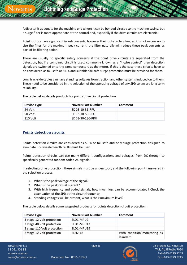
Points drive circuits
These circuits power the drive to the electric motor in a points machine or electric trainstop. In some cases, they are unidirectional but for most point machines the circuits are reversable, either in phase rotation or circuit polarity, such that the points mechanism can be driven in two directions. They can be considered as a power circuit and as with signal lighting circuits protection at both ends of the circuit is required as cables can be hundreds of meters long. Common mode is the dominant effect and can cause breakdown of the points machine motor, control relays or electronics.
Novaris Pty Ltd 33 061 301 88 novaris.com.au [email protected]
Page 16 Document No: 0015-D63V1
72 Browns Rd, Kingston TAS, AUSTRALIA 7050
Tel +613 6229 7233 Fax +613 6229 9245
A diverter is adequate for the machine end where it can be bonded directly to the machine casing, but a surge filter is more appropriate at the control end, especially if the drive circuits are electronic. Point motors have significant inrush currents, however their duty cycle is low, so it is not necessary to size the filter for the maximum peak current; the filter naturally will reduce these peak currents as part of its filtering action. There are usually no specific safety concerns if the point drive circuits are separated from the detection, but if a combined circuit is used, commonly known as a “4-wire control” then detection signals are switched onto the same conductors as the motor. If this is the case these circuits have to be considered as fail-safe or SIL-4 and suitable fail-safe surge protection must be provided for them. Long trackside cables can have standing voltages from traction and other systems induced on to them. These need to be considered in the selection of the operating voltage of any SPD to ensure long term reliability. The table below details products for points drive circuit protection.
Device Type Novaris Part Number Comment
24 Volt SDD3-10-31-RPU
50 Volt SDD3-10-50-RPU
110 Volt SDD3-30-130-RPU
Points detection circuits
Points detection circuits are considered as SIL-4 or fail-safe and only surge protection designed to eliminate un-revealed earth faults must be used. Points detection circuits can use many different configurations and voltages, from DC through to specifically generated random coded AC signals. In selecting surge protection, these signals must be understood, and the following points answered in the selection process:
1. What is the peak voltage of the signal? 2. What is the peak circuit current? 3. With high frequency and coded signals, how much loss can be accommodated? Check the
attenuation of the SPD at the circuit frequency 4. Standing voltages will be present, what is their maximum level?
The table below details some suggested products for points detection circuit protection.
Device Type Novaris Part Number Comment
3 stage 12 Volt protection SLD1-MPU9
3 stage 48 Volt protection SLD1-MPU13
3 stage 110 Volt protection SLD1-MPU19
2 stage 12 Volt protection SLH2-18 With condition monitoring as standard

Novaris Pty Ltd 33 061 301 88 novaris.com.au [email protected]
Page 17 Document No: 0015-D63V1
72 Browns Rd, Kingston TAS, AUSTRALIA 7050
Tel +613 6229 7233 Fax +613 6229 9245
2 stage 24 Volt protection SLH2-36 With condition monitoring as standard
2 stage 50 Volt protection SLH2-68 With condition monitoring as standard
2 stage 110 Volt protection SLH2-130 With condition monitoring as standard
Axle counters
Axle counters are gradually taking over from track circuits for many applications due to their lower cost and less interaction with traction current return systems on electrified railways. They often use manufacturer specific signalling protocols with detailed safety restrictions on what can be attached to the cables. Current manufacturers of axle counters are:
• Frauscher Sensor Technology
• Thales
• Siemens
• Altpro
• Tiffenbach Axle counters generally fall into two categories: wheel flange detectors and wheel detectors. They can be distinguished by the detectors mounted to the running rail. Flange detectors have a single detector mounted on the inside of the rail while wheel detectors have a detector on both sides of the rail. Flange detectors are usually connected directly back to the control electronics via long trackside cables whereas wheel detectors usually have a small “mushroom” at the trackside with some local electronics to process the detector signals into a more complex protocol for transmission back to the control system (evaluator). Most systems will be provided with some SPDs by the manufacturer but often these are proven as not adequate to protect against strong lightning in tropical regions. Novaris manufactures the SPDs for the Siemens ACM100, ACM200 and ACM250 range of axle counters. These are available direct from Siemens under a Siemens part number or direct from Novaris. Novaris can design and test specific SPDs for these systems provided that all the design information and safety restrictions are provided. This is how the ACM protection units were developed in direct collaboration with Siemens AG. The table below details products for Axle counter circuit protection
Device Type Novaris Part Number Comment
ACM 100 Contact Novaris for details Siemens
ACM 200 Contact Novaris for details Siemens
ACM 250 Contact Novaris for details Siemens

Novaris Pty Ltd 33 061 301 88 novaris.com.au [email protected]
Page 18 Document No: 0015-D63V1
72 Browns Rd, Kingston TAS, AUSTRALIA 7050
Tel +613 6229 7233 Fax +613 6229 9245
2 stage 12 Volt protection SLH2-18 With condition monitoring as standard
2 stage 24 Volt protection SLH2-36 With condition monitoring as standard
2 stage 50 Volt protection SLH2-68 With condition monitoring as standard
2 stage 110 Volt protection SLH2-130 With condition monitoring as standard
Miscellaneous input and output circuits
Most signalling installations will have a range of these circuits for detecting external objects, eg drag sensors, bearing sensors, carriage RFID or for driving outputs for level crossing controls, ground frame releases etc. The signalling designer should analyse the safety requirements of the circuit and use a fail-safe type SPD if required. For circuits that are not safety related Novaris manufactures a full range of SPDs for all types of electrical signals and protocols. The Novaris Product Handbook contains a table of signals and protocols along with recommendations on the appropriate Novaris product to protect them. The table below details products for miscellaneous circuit protection.
Device Type Novaris Part Number Comment
3 stage 12 Volt protection SLD1-MPU9
3 stage 48 Volt protection SLD1-MPU13
3 stage 110 Volt protection SLD1-MPU19
2 stage 12 Volt protection SLH2-18 With condition monitoring as standard
2 stage 24 Volt protection SLH2-36 With condition monitoring as standard
2 stage 50 Volt protection SLH2-68 With condition monitoring as standard
2 stage 110 Volt protection SLH2-130 With condition monitoring as standard
Line circuits
These are circuits that pass signalling, usually safety related, controls and indications between one housing and another over long distances, often up to 1000m or more. There are several ways that this is done from basic DC signalling relay circuits to polarity sensitive polar circuits and serial or FDM telemetry for non-vital indications.

Novaris Pty Ltd 33 061 301 88 novaris.com.au [email protected]
Page 19 Document No: 0015-D63V1
72 Browns Rd, Kingston TAS, AUSTRALIA 7050
Tel +613 6229 7233 Fax +613 6229 9245
Different countries and rail authorities use different systems. 24 volt and 50 volt DC are the most common for relay based line circuits. With computer based interlockings becoming the global standard there are higher risks of damage with more vital circuits coming from outdoor equipment directly to electronic inputs/outputs on CBI printed circuit boards. These circuits need to be protected from common and transverse mode disturbances. The table below details products for line and CBI I/O circuit protection.
Device Type Novaris Part Number Comment
3 stage 12 Volt protection SLD1-MPU9
3 stage 48 Volt protection SLD1-MPU13
3 stage 110 Volt protection SLD1-MPU19
2 stage 12 Volt protection SLH2-18 With condition monitoring as standard
2 stage 24 Volt protection SLH2-36 With condition monitoring as standard
2 stage 50 Volt protection SLH2-68 With condition monitoring as standard
2 stage 110 Volt protection SLH2-130 With condition monitoring as standard
3 stage 12 Volt protection SLD1-MPU9
Wiring for best performance
To achieve the best results from Novaris surge protection some basic wiring conventions need to be followed. SPDs need to be installed correctly as per the manufacturer’s instructions. The SPD components are carefully designed and coordinated to provide a reduction in the level of voltage from the line side through to the protected, equipment side. Units are labelled in the following ways:
1. Line Side (L1, L2 etc). This is the side where the surges will come from, often called the dirty side and is where external cables are terminated on a typical termination rack or location frame.
2. Equipment Side (E1, E2 etc). This is the side where the equipment to be protected is
terminated and is often called the load or clean side for power applications.
3. Earth. This should be made primarily with the DIN or G mounting rail as the main earth path with the mounting rails bonded into a matrix as detailed on page 4. Earth cables from other
Novaris Pty Ltd 33 061 301 88 novaris.com.au [email protected]
Page 20 Document No: 0015-D63V1
72 Browns Rd, Kingston TAS, AUSTRALIA 7050
Tel +613 6229 7233 Fax +613 6229 9245
cubicles and racks should be connected towards the centre of this bonded matrix to minimise the voltages developed between items of equipment when the SPD(s) conduct a surge current.
The orientation of the SPDs need to be Line side to Line side to provide proper protection. For example, a long signalling cable running between two location cases will need the SPD at each end to be oriented with the ‘Line’ side terminals connected to the cable. The surges will be coming from the exposed cable and the SPD at each end provides the ‘Point of Entry’ protection for the equipment inside the locations. Cables for bonding mounting rails to the main earth point should be as large as can be physically handled in the room or location. An ideal cable for this would be a Green/Yellow earth wire with a stranding of 360/0.5mm giving 70mm² with good high frequency performance and flexibility.
Basic rules for signalling surge protection
The following basic guidelines should be used in the selection and installation of electrical surge protection equipment for railway signalling and other associated railway systems.
1. Consider the safety level of the circuits and choose appropriate devices 2. Use the mounting rails as the ground connection and bond all rails in a matrix 3. Connect equipment earths to this matrix, not to a separate earth bar or plate 4. Bond the surge protection and equipment earths together at each end of external circuits 5. Apply protection at all points of entry to buildings and locations 6. Consider the maximum standing voltages that may be present on cables 7. Keep wiring as short and straight as possible 8. Mount the surge protection as close to the equipment as possible 9. Test for follow on currents on DC circuits 10. Protect sensitive electronic circuits first
Other railway applications
Novaris has provided surge protection for other railway systems, including the following:
• Platform screen doors
• PA speakers
• PA amplifiers and digital voice annunciation equipment
• Hearing loops
• CCTV
• Emergency help points
• Information call points
• Emergency stop plungers
• LED lights
• Passenger information systems
• On board circuit and antenna protection
• Automatic fare collection machines

Novaris Pty Ltd 33 061 301 88 novaris.com.au [email protected]
Page 21 Document No: 0015-D63V1
72 Browns Rd, Kingston TAS, AUSTRALIA 7050
Tel +613 6229 7233 Fax +613 6229 9245
• Pedestrian gates
• Card readers For these applications please contact Novaris directly to get advice on the most appropriate products.
Other voltage and protocol protection
Novaris manufactures a full range of products for the protection of other voltages and protocols not mentioned in this application note. For the complete range of Novaris products please see our Web site www.novaris.com.au or contact us at [email protected]
Bibliography
Robert Jordan is the Principal Engineer at Novaris. He is a career railway signalling and electrical engineer with over 34 years of experience mostly in Mass Rapid Transit systems and product development. He is a full member of the Institute of Railway Signalling Engineers and in 1998 he won the Institute of Engineers Australia, Railway Engineering Award for pioneering work on the development of failsafe surge protection for computer based interlocking equipment.