rail vehicle impact analysis: the instable propensity of ... · impact loads; second, high shear...
TRANSCRIPT
Original Article
Rail vehicle impact analysis: The instablepropensity of structural responses and thecritical scenarios of structural failure
Xiangdong Xue1, Roderick Smith2, Felix Schmid3 andMark Robinson1
Abstract
In this paper, the authors investigate the characterisation of the structural collapse of steel-bodied rail vehicles and
propose modifications to a cab structure for improved structural crashworthiness. This is a mechanical- and simulation-
based investigation, comprising three parts: after a mechanical description of the impact forces and energy conservation
in collisions between trains, the characteristics of rail vehicle structures are examined to identify structural weaknesses
in the context of impact stability. This is followed by a computer simulation of a cab structure to validate the conclusions
from the theoretical analysis and to demonstrate the effectiveness of the design modifications. Focusing on the correl-
ation between structural characterisation and impact stability, the authors highlight the following three findings: first, rail
vehicles have a propensity to be unstable in the vertical direction due to the asymmetrical geometry and unbalanced
impact loads; second, high shear stresses tend to be generated at the top corners of the rear pillars of the door region,
leading to a localised fracture tendency; and third, impact stability can be enhanced through structural modifications
by adopting symmetric cross sections or enhancing the stiffness in the weak direction for asymmetric structures,
i.e. achieving geometric symmetry or stiffness balance on impact. The findings result in a better understanding of the
mechanisms in structural crushing and advance the research into passive safety of rail vehicles.
Keywords
Impact stability of rail vehicles, crushing characterisation of rail vehicles, design modification of rail vehicles, passive safety
of rail vehicles, computer simulation of structural collisions
Date received: 14 April 2014; accepted: 6 August 2014
Introduction
The geometry and structure of rail vehicles allow themto cope with the characteristics of their operation.Longitudinally coupled by hinged couplers, verticallysuspended on bogies and mechanically driven throughthe tiny patches of the wheel/rail contact, rail vehiclesmove in a flexible arrangement in a coordinatedmanner. In unexpected incidents, e.g. collisions, railvehicles often experience unstable or irregular behav-iours beyond their design scope. The irregularresponses fall into two types, namely, motionsbeyond the bounds of the limitations of the degreesof freedom, as defined by the suspension and couplingsystems between the structural parts, and those cre-ated by plastic deformation within structural parts.The collision responses of rail vehicles can thus beclassified into two categories: first, the dynamicresponse measured by the motion of the vehicle as awhole, experienced as a change in kinetic energy; andsecond, the deformation response to structural col-lapse of the vehicle, observed as a change in potential
energy. Energy conversion between kinetic and poten-tial energies and dissipation through external workthus play fundamental roles in rail vehicle impacts.
In terms of kinetic energy due to structural move-ments, the impact responses of rail vehicles are closelycorrelated with the amount of kinetic energy releasedby the structural movements during the impact.Correspondingly, train impacts are generally classifiedinto two categories: high-energy impacts and low-energy impacts, where the energy level is defined bythe amount of energy dissipated through structuraldeformation. Trains running at low speeds can onlybe involved in low-energy impacts, whereas trains
1School of Mechanical and Systems Engineering, Newcastle University,
UK2Department of Mechanical Engineering, Imperial College, London, UK3School of Civil Engineering, University of Birmingham, Birmingham, UK
Corresponding author:
Xiangdong Xue, School of Mechanical and Systems Engineering,
Newcastle University, Newcastle upon Tyne, NE1 7RW, UK.
Email: [email protected]; [email protected]
Proc IMechE Part F:
J Rail and Rapid Transit
2016, Vol. 230(3) 681–696
! IMechE 2014
Reprints and permissions:
sagepub.co.uk/journalsPermissions.nav
DOI: 10.1177/0954409714555382
pif.sagepub.com
by guest on February 22, 2016pif.sagepub.comDownloaded from

running at high speeds may experience either high- orlow-energy impacts. The high level of kinetic energystored within a fast-moving impacted train may beeither dissipated through structural deformation, i.e.leading to a high-energy impact, or remain high afterthe impact, i.e. resulting in a low-energy impact. Thelatter behaviour occurs where a train collides with acar at a road level crossing. Crashworthiness studiesthus require multiple approaches, including the tworesponses as follows: first, the structural collapse ofrail vehicles, dominant in high-energy impacts; andsecond, the movement stability of trains, dominantin low-energy impacts.
In terms of the potential energy generated by struc-tural deformation, the response of rail vehicles isclosely related to the vehicle’s structure, i.e. thenature of components and the ways in which theyare assembled. Modern rail vehicles are good exam-ples of state-of-the-art structures in being light inweight and in terms of their production techniquesand spatial efficiency. The main bodies of rail vehiclesare thin-walled tubes, built with a steel skin and rein-forced by integrated stiffeners of pressed steels. At theends of the tube, there are either end walls or cabstructures. The vehicle bodies are flexibly connectedwith each other in the longitudinal direction throughcoupling systems and are individually supported onbogies. Auxiliary equipment is suspended beneaththe underframe to enable increased stability throughlowering of the centre of gravity. In collisions, the cabstructure experiences the initial impact at the leadinginterface. This is followed by intermediate impactsbetween vehicles, spreading from the coupling systemsto the vehicle ends. For non-articulated rail vehicles,bogies are usually not directly involved in the struc-tural collapse. However, they play a key role in theimpact stability of the vehicles.
The contribution of individual components, e.g.strengthening tubes, to the crashworthiness of thestructures of rail vehicles is determined by their crush-ing behaviours under laboratory conditions and inrealistic scenarios when the tubes are installed in vehi-cles. Energy absorbers in rail vehicles are devices orcomponents that have a specific role: the energyabsorber is the only component that is specificallydesigned for the purpose of energy absorption with-out being required to perform other duties. A varietyof types of energy absorbers are therefore potentiallyapplicable to rail vehicles. The energy absorber in railvehicles is required to cope with the in-vivo environ-ment of rail vehicles, including coordinating withother components and behaving in a stable mannerduring the collapse of the vehicle structure. Hence,apart from the general characteristics required foran energy absorber, energy absorbers for rail vehiclesmust demonstrate their functionality in different com-plex scenarios. A great deal of work has been done onthe in-vitro behaviours of tube-shaped energy absor-bers, including different shaped cross sections,
e.g. square, circle and tapered tubes, and differentmaterials, e.g. steels, aluminium and composites.1–3
In addition to conventional simple tube devices,work on energy absorbers based on foam-filledtubes4 is also attracting increased interest. In termsof the in-vivo behaviours of tubes, the work focuseson how to retain the in-vitro behaviours of tubes inrealistic structures. In this respect, oblique impacts oftubes5 and dynamic sensitivity of tubes have particu-lar relevance.
The requirements for structural collapse stabilityand energy dissipation efficiency often lead to con-flicts, as the former requires a soft response by thestructure and the latter demands a reasonable levelof stiffness. Structural stiffness also affects thedynamic response of an entire vehicle, e.g. in theway accelerations are managed. A compromisebetween these two is often required for crashworthydesigns. To increase collapse stability, couplers aredesigned with a shear-off or push-back structure,which enables the coupler to be removed from thecollapse zone in the event of a collision.6 To increaseenergy absorption, energy absorbers7 can be installedin the end regions of vehicles for increased structuralstability and force/displacement behaviour. Toincrease the stability of the rear part when a regularcollapse of the front occurs, the forces are designed ina pattern that gradually increases through differentcollapse stages.8 The above measures have led to theformation of a well-accepted crashworthy design prin-ciple, in which rail vehicles are designed to deform in acontrolled pattern progressively from couplers, toenergy absorbers and the end structure, so that thekinetic energy of impact vehicles can be effectivelydissipated outside passenger holding areas.8–10
The structural behaviour of rail vehicles in colli-sions is closely related to occupant responses, as theprimary impact of rail vehicle structures is followedby the secondary impact of occupants with vehicleinteriors. The impacts between structures and occu-pants show a series of sequences from outside toinside, as follows.
1. The structural impact, including the initial impactand any consequential impacts after a derailment,results in structural collapses and accelerations.
2. Occupant impacts follow and are affected by theinterior layout and vehicle accelerations.
3. The biomechanics impact on the occupants’organs is then promoted by body decelerationsgenerated by impacts with interior components.
In the structural impact, the dynamic response ofthe structure is the cause for the accelerations and thestructural deformation is the means for energyabsorption. For the second and third terms of occu-pant impact behaviours, the dynamic response is illu-strated by the whole-body behaviour and studied bydummy dynamics. The deformation responses of
682 Proc IMechE Part F: J Rail and Rapid Transit 230(3)
by guest on February 22, 2016pif.sagepub.comDownloaded from

organs, e.g. crushing of the brain, leakage of bloodvessels and fracture of bones, often lead to more ser-ious consequences than contact damage of externalsurfaces of occupants. In view of the differences onphysics and materials, the above three terms are oftenstudied separately by different research programmes.This paper focuses on structural responses of rail vehi-cles and, specifically, the stability in collisions.
Considerable work has been done in the last threedecades in pursuing efficient energy dissipation in thedesign of rail vehicles. The late-1980s are generallyconsidered as the datum line for the development ofcrashworthy rail vehicles. The following two decades,crashworthiness of rail vehicles had a ‘golden age’.Through intensive research projects carried out bythe European Research Office Question 16511, BritishRail8 and French Railways9, a good understanding ofthe impact responses of rail vehicles was obtained andthe crashworthy design principles were established.Followed by further enhanced research throughextended European projects (i.e. SAFETRAIN,SAFETRAM, TRAINSAFE, SAFEINTERIORS,ALJOIN, etc.) and the extensive US programmes10,crashworthy design and manufacturing have becomean essential requirement within the rail industry.12,13
The destructive nature of structural impacts andthe scattering behaviour of dynamic responses deter-mine that the three major analysis techniques: theor-etical description, computer simulation, andexperimental validation, must be applied in a differentmanner from conventional service-based applications.Due to the resulting destruction, full-scale dynamictests are more suitable as a means of validation forrepresentative scenarios. Because of the high cost ofsuch tests, impact experiments often concentrate oncomponents and, due to the variations in dynamictests, generally start from quasi-static tests. Thebehavioural variations between standalone andinstalled components and between quasi-static anddynamic situations continue to pose challenges inappropriately evaluating experimental results to pre-dict the behaviours of components when installed inrail vehicle systems. Theory-based studies and com-puter simulations are thus expected to play anincreased role in train impact research, in particularfor design prediction of new products and for theadvanced stages of refining designs where experienceand practical results are lacking.
Computer simulation faces different challengesfrom those for impact tests. Although the representa-tiveness of testing is restricted by scenario availability,computer simulation is still required to validate thevirtual prediction result against reality. In this respect,computer simulation and testing are closely linked. Asa virtual approach, the accuracy of computer simula-tions is affected by both the expression of physicalphenomena and the implementation of scenariodetails. Simulation accuracy can be increased if thesetwo factors are treated separately. As a general rule,
the first step must be to achieve an agreement betweenthe simulation and test results to obtain a validatedphysics model. This can then be followed by focusingon the influence of different scenario specifications.A distinct advantage of theoretical analysis andnumerical simulation is their convenience for predic-tion and comparison. As soon as a numerical setting isvalidated and theoretical analysis is rectified withexisting practical cases, they can be easily extendedto investigate a variety of new scenarios, to trace fun-damental issues and to interpret quasi-static experi-ments. The resulting theories and numerical methodsdeveloped can in-turn provide guidance for furtherdesign and enhancement of products.
The work on impact safety of trains has been domi-nated, to date, by studies of the crashworthiness of railvehicles, in the designs that exhibit a controlled regularcrushing behaviour. This approach focuses on stableresponses, from a positive perspective, that is, on howwell rail vehicles perform in collisions and how theyprevent impact fatalities. In view of the wide variationsof dynamic responses and impact scenarios though, itis also necessary to study the impact/crash stability oftrains by focussing on the irregular crushing behav-iours of rail vehicles that arise when impact conditionsand responses go beyond the design scope. The ana-lysis of impact stability covers unstable responses,from a negative viewpoint, i.e. how poorly mightrail vehicles behave in collisions and how couldimpact damage be reduced. Crash-worthiness andcrash-stability analyses thus examine the impactbehaviours of trains from two different angles. A com-bination of the two approaches can create a compre-hensive picture of train collisions and lead to a betterunderstanding of this phenomenon.
The authors of this paper study the impact stabilityof rail vehicles by analysing structural collapse behav-iours, i.e. inside the vehicle. This paper can be con-sidered as a companion to our recent publication14
where the focus was on rail vehicle interactions withoutside environments on the basis of the entire system,including the pitfalls of the rigid-wall model and sym-metric behaviour assumptions. The next section gives amechanical description of the impact forces and energyconservation in train collisions. The structural charac-teristics and impact weaknesses of rail vehicles are thenexamined and discussed in the section ‘Mechanicalanalysis of the impact stability of rail vehicle’, whichis followed, for validation purposes, by computersimulations of cab vehicle impacts in the section‘Computational analysis and structural modification’.
Mechanical and mathematicaldescriptions
Force generation in train collisions
The force is the cause and the energy is the conse-quence of structural responses in train collisions.
Xue et al. 683
by guest on February 22, 2016pif.sagepub.comDownloaded from

The fundamental purpose of adjusting the structuraldeformation response is to establish an effective con-version route between impact forces and structuralenergy, where the prevention of unstable structuralresponses is an important objective in supportingcrashworthiness.
The following three types of forces are the maincontributors in train collisions.
1. Contact forces. Applied on boundary interfaces.As an interaction-based phenomenon, the magni-tude of impact forces on the impact interface isextremely high, which leads the passive supportforces on the wheel/rail interfaces often to be ina chaotic state.
2. Field forces. Applied in solid volumes by gravita-tional effect. In many cases, the gravitational forcemakes a balancing contribution on the vehicles inthe vertical direction, which results in irregularresponses of rail vehicles to be dominant in thetransverse direction.
3. Inertial/dynamic forces. Applied on bodies asso-ciated with accelerations. Under high impactforces, the vehicle structure shows strong dynamicresponses, manifesting themselves as the inertialresponse of the vehicle as a whole and as inter-active responses between vehicle parts.
The above forces determine the following charac-teristics of train collisions.
1. A transient dominant process. Rail vehicle colli-sions last only a short time but result in destructiveconsequences, illustrating features of a dramaticprocess and fast dispersion. With a high aspectratio of length to transverse sizes, wave propaga-tion dominates over structure vibration.
2. Progress from external to internal. Internalresponses of inertial behaviour and deformationare passive consequences of an external impactforce acting on the interfaces. Structural impactthus represents an enforced process from the out-side to the inside. As such, the immediate responseoften comes from the dynamic response of theentire structure. A vehicle’s internal responsesthen happen in expansion stages.
3. Different responses between vertical and lateral dir-ections. The impact forces are likely to scatteralong the vertical direction, however, the irregularresponses often appear in the transverse direction.The initial impact force is mainly on the under-frame that is weak under vertical bending.However, large gravitational loads can easilyoffset small forces. By contrast, there is no con-straint and equilibrium forces in the transverse dir-ection. Irregular transverse responses often lead touncontrolled dynamic developments.
4. Varying damage modes between vertical and lateraldirections. Corresponding to term 3, the damage in
the vertical direction often shows force/deform-ation features and the damage in the transversedirection possesses dynamic movement features,either in translational or rotational modes.
The correlation of forces and vehicle responses canbe expressed as follows
M €uþ Ku ¼ FðtÞ ð1Þ
where M and K are the mass and stiffness matrices ofthe vehicle structure, u is the displacement vector atnodes (structural deformation as relative note dis-placements) and F(t) is the external force vector.F(t) refers to the impact force in the horizontalplane but needs to take into account gravitationalloads and rail support forces if the vertical directionis considered. The first term on the left-hand side ofequation (1) defines the acceleration ( €u) response ofthe vehicle (M) and the second term describes thestiffness response (K) over the notes (u) of thestructure.
Equation (1) shows that a collision results in twoconsequences, the inertial motion of the entire vehicleand the structural deformation of the vehicle. As themass matrix M is relatively constant, the responses ofthe vehicle are mainly determined by the stiffnessmatrix K, i.e. the assembly manner of the vehiclestructure. Hence, from the point of view of theforce, structural crashworthiness denotes a processfor building the vehicle to achieve an appropriate stiff-ness distribution.
The inertial response by the first term on the left-hand side of equation (1) concerns the kinetic energyof the vehicle and the deformation response in thesecond term is related to the potential energy of thevehicle. The correlation between kinetic and potentialenergies is described by the energy conservation law.
Energy conversion in train collisions
The generation of potential energy through structuraldeformation is promoted by the kinetic energy of thetrains. During train collisions, the enormous amountof kinetic energy of the impact train(s) is converted topotential energy or dissipated through external work.The conversion of energy follows energy conservationlaws, a derivation of the Lagrangian principle of theleast action15, expressed as
�ðEþUÞ ¼Wex ð2aÞ
ðEpost þUpostÞ � ðEpre þUpreÞ ¼Wex ð2bÞ
where E and U are the kinetic and potential energies,subscripts pre and post refer to the moments beforeand after an impact, Wex is the work done on thesystem by external forces, which is positive ifthe total amount of energy increases. The terms of
684 Proc IMechE Part F: J Rail and Rapid Transit 230(3)
by guest on February 22, 2016pif.sagepub.comDownloaded from

the kinetic and potential energies on the left-hand sideof equation (2) belong to state variable/functions, i.e.they are path-independent. By contrast, the externalwork Wex on the right-hand side of equation (2) ispath-dependent, requiring accumulations overdisplacements.
The definition of domain boundaries for the pur-pose of counting external and internal work is amatter of choice and is based on calculation conveni-ence. For the regions selected within the domain, theinternal work does not have a contribution to thetotal energy, as based on Newton’s Third Law,which states that all the internal forces appear aspairs and their effects are offset. Hence, when twotrains that are involved in a collision are taken intoan isolated domain system, all the interactionsbetween the vehicles belong to the internal domain,leading to a zero external energy Wex in equation (2),on all the impact interfaces. However, whereas theinternal work does not affect the total energy, itdoes change the energy type between kinetic andpotential forms through structural deformation. Thecontribution of internal work to structural potentialenergy can be expressed as
�U ¼ Upost �Upre ¼Win ð3Þ
where Win denotes the internal work due to structuraldeformation from internal forces, an important termfor structural crashworthiness. Substituting equation(3) into equation (2a), we have
Wex ¼ �Eþ�U ¼ �EþWin ð4Þ
Equation (4) describes the impact interaction whenonly one of the impacting and impacted parts isincluded. Taking the example where the impactedvehicle is stationary, the impact on the interface,which is an external force as one vehicle is selected,leads to two consequences. Based on equation (4), onepart of the interface impact is converted into kineticenergy of the vehicle �E and the other part is con-verted into potential energy by the internal work Win.The more of the potential energy that is convertedinto structural deformation, the less the amount ofkinetic energy generated. The functionality of theinternal work and the external work can thus be con-cluded as follows: the internal work converts kineticenergy to potential energy through structural deform-ation, whereas the external work promotes the changeof the kinetic energy through system interaction withoutside objects or environment. In other words, inter-nal work targets the mechanical behaviour insidevehicles and external work concerns the dynamicbehaviour of vehicles as a whole.
For the convenience of analysis, the potentialenergy previous to the impact is set to zero, i.e.Upre ¼ 0. If the impacting and impacted vehicles aretaken into the single domain system, the work by
impact forces on the interfaces falls into the internaldomain. In this case, the work by external forces, e.g.frictional work, can be ignored. Equation (2b) canthus be simplified to
Epre ¼ Epost þUpost ð5Þ
Equation (5) shows the energy conversation when theimpacting and impacted vehicles are included in asingle system. According to equation (5), the aim toreduce the kinetic energy after the impact can berealised by increasing the potential energy throughstructural deformation. Note that, in this caseUpre ¼ 0. From equation (3), the potential energyafter the impact can be expressed as
Upost ¼Win ¼WinB þWin
S ð6Þ
where the subscripts B and S refer to the sets of beamsand shells of the rail vehicle structure in a cross-sec-tion. Equation (6) shows that the structural internalwork for the potential energy can be divided into twogroups, that generated by beams and that by shells.Expressed by individual members, equation (6)becomes
Upost ¼Xi
WinBi þ
Xj
WinSj
¼Xi
Z Xi
0
FBi dxþXj
Z Xj
0
FSj dxð7Þ
where indexes i and j refer to individual componentsin beam and shell sets, respectively, Xi and Xj are thelengths to which the relevant components are crushed.Equation (7) shows that the ability to absorb energy isconcerned with the number of beams and shells thatare involved in the structural collapses and the extentto which individual components are crushed.Therefore, structural impact stability, i.e. the crushinglengths of Xi and Xj, are crucial for structural crash-worthiness of rail vehicles.
Mechanical analysis of the impactstability of rail vehicles
Weakness characterisation of rail vehicles instructural collisions
Figure 1 shows the structure of the front part of thecab vehicle studied in this paper. Corresponding tothe key issues on structural impact stability discussedon thin-walled tubes in the previous section, the cabvehicle structure shows the following characteristics.
1. Geometry. The cab vehicle possesses a symmetricgeometry in the lateral direction and a non-sym-metric geometry in the vertical direction. As aresult, the cab vehicle experiences structural
Xue et al. 685
by guest on February 22, 2016pif.sagepub.comDownloaded from

instability in the vertical direction. With half aconical cab structure in the vertical direction, theweakness for vertical instability is towards down-wards bending.
2. Stiff distribution. Very stiff, e.g. the bolster, andvery soft, e.g. door regions, sections/parts areembodied in panels. Uncoordinated responsesare likely to be induced when relevant sectionsare involved in crushing actions.
3. Composition. The framework of the cab vehicle iscomposed of reinforced beams with conventionalopen sections, i.e. channels, angles and I-beams.This indicates that, apart from the correspondingrequirement between different panels in simpletubes, rail vehicles should also take into accountthe coordination localised between shells and asso-ciated beams.
4. Structural patterns. The underframe is muchstronger and thicker than the side panels androof. For crashworthiness designs, the underframeshould be treated as a beam-dominated part cov-ered with a thin plate, whereas the side panels androof should be considered as panel-dominatedthin-wall parts reinforced by beams. This differ-ence in structural pattern indicates that the crush-ing manner of the underframe tends to be differentfrom the side panels and roof.
The above characteristics highlight the differencesbetween rail vehicles and simple tubes. These charac-teristics are the common features in modern rail vehi-cles, particularly for steel vehicles. This determinesthat the rail vehicle collapse is a more complex processthan for a tube with flat plates. The purpose of thecomplex pattern of rail vehicle structures is to achieveglobal stiffness, which brings increased challenges forlocalised collapses. Promotion of local collapses orbending is thus the key matter for the structuralimpact stability of rail vehicles.
The construction of the structure of a rail vehiclehas benefitted from using state-of-the-art pressed
thin-walled structures, although this creates two chal-lenges for further development.
1. The optimised structures leave limited space forimplementing extra safety measures without alter-ing the existing structural pattern. Consequently,unless there is a fundamental change, furthermodifications for crashworthiness would necessi-tate a compromise or some sacrifice from otheraspects of the structural performance.
2. Continuous use of conventional standard sectionsof beams leads to crashworthy rail vehicles look-ing like a hybrid product, in which the global pro-file and assembly pattern are constructed based oncrashworthy requirements (in particular, the vehi-cle’s end structures), whereas most of the localisedcomponents are still in conventional forms. Theonly exception is the newly supplemented energyabsorber. This has hindered a systematic crash-worthiness design of rail vehicles from thebottom-up. As a result, defects at the componentlevel tend, frequently, to appear in collisions.
Bending weakness: Downward bending tendency ofrail vehicles at impact ends
This weakness corresponds to the characteristics of thenonsymmetric geometry in the vertical direction andbeam assembly pattern of the underframe. Figure 2depicts the forces and relevant structural details atthe impact end of the cab vehicle. The instability effectsdue to vehicle geometry, structural compositions andimpact forces are summarised as follows.
Instability due to unbalanced structures.
1. End structure of the cab vehicle. The underframe,the strongest part in the vehicle, is connected withcab panels (side panels at the vehicle’s centre) onthe top, but is empty underneath. For any upwardbending moment of the underframe, the top
Figure 1. Structural view of the front part of the cab vehicle (lead vehicle with cab).
686 Proc IMechE Part F: J Rail and Rapid Transit 230(3)
by guest on February 22, 2016pif.sagepub.comDownloaded from
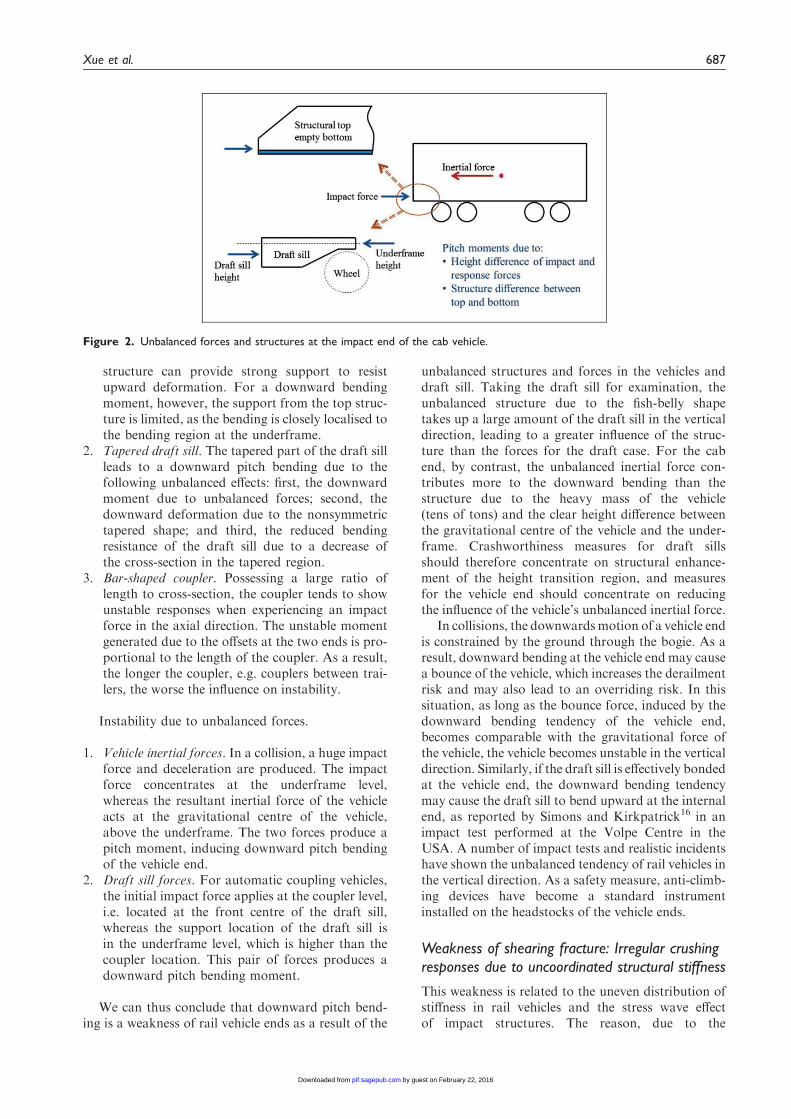
structure can provide strong support to resistupward deformation. For a downward bendingmoment, however, the support from the top struc-ture is limited, as the bending is closely localised tothe bending region at the underframe.
2. Tapered draft sill. The tapered part of the draft sillleads to a downward pitch bending due to thefollowing unbalanced effects: first, the downwardmoment due to unbalanced forces; second, thedownward deformation due to the nonsymmetrictapered shape; and third, the reduced bendingresistance of the draft sill due to a decrease ofthe cross-section in the tapered region.
3. Bar-shaped coupler. Possessing a large ratio oflength to cross-section, the coupler tends to showunstable responses when experiencing an impactforce in the axial direction. The unstable momentgenerated due to the offsets at the two ends is pro-portional to the length of the coupler. As a result,the longer the coupler, e.g. couplers between trai-lers, the worse the influence on instability.
Instability due to unbalanced forces.
1. Vehicle inertial forces. In a collision, a huge impactforce and deceleration are produced. The impactforce concentrates at the underframe level,whereas the resultant inertial force of the vehicleacts at the gravitational centre of the vehicle,above the underframe. The two forces produce apitch moment, inducing downward pitch bendingof the vehicle end.
2. Draft sill forces. For automatic coupling vehicles,the initial impact force applies at the coupler level,i.e. located at the front centre of the draft sill,whereas the support location of the draft sill isin the underframe level, which is higher than thecoupler location. This pair of forces produces adownward pitch bending moment.
We can thus conclude that downward pitch bend-ing is a weakness of rail vehicle ends as a result of the
unbalanced structures and forces in the vehicles anddraft sill. Taking the draft sill for examination, theunbalanced structure due to the fish-belly shapetakes up a large amount of the draft sill in the verticaldirection, leading to a greater influence of the struc-ture than the forces for the draft case. For the cabend, by contrast, the unbalanced inertial force con-tributes more to the downward bending than thestructure due to the heavy mass of the vehicle(tens of tons) and the clear height difference betweenthe gravitational centre of the vehicle and the under-frame. Crashworthiness measures for draft sillsshould therefore concentrate on structural enhance-ment of the height transition region, and measuresfor the vehicle end should concentrate on reducingthe influence of the vehicle’s unbalanced inertial force.
In collisions, the downwardsmotion of a vehicle endis constrained by the ground through the bogie. As aresult, downward bending at the vehicle end may causea bounce of the vehicle, which increases the derailmentrisk and may also lead to an overriding risk. In thissituation, as long as the bounce force, induced by thedownward bending tendency of the vehicle end,becomes comparable with the gravitational force ofthe vehicle, the vehicle becomes unstable in the verticaldirection. Similarly, if the draft sill is effectively bondedat the vehicle end, the downward bending tendencymay cause the draft sill to bend upward at the internalend, as reported by Simons and Kirkpatrick16 in animpact test performed at the Volpe Centre in theUSA. A number of impact tests and realistic incidentshave shown the unbalanced tendency of rail vehicles inthe vertical direction. As a safety measure, anti-climb-ing devices have become a standard instrumentinstalled on the headstocks of the vehicle ends.
Weakness of shearing fracture: Irregular crushingresponses due to uncoordinated structural stiffness
This weakness is related to the uneven distribution ofstiffness in rail vehicles and the stress wave effectof impact structures. The reason, due to the
Figure 2. Unbalanced forces and structures at the impact end of the cab vehicle.
Xue et al. 687
by guest on February 22, 2016pif.sagepub.comDownloaded from

non-coordination of the stiffness on the crushing sec-tion, is discussed in the following using stress wavepropagation concepts. The equation for a stresswave in a uniform long bar (without a need to con-sider deflected waves) can be expressed as17
@2u
@t2¼ c2
@2u
@x2ð8Þ
where
c2 ¼1
�
@�
@"¼
k
�ð9Þ
In equations (8) and (9), u is the particle displacementalong bar axis x, c is the wave propagation velocity,� is the material density, � and " are the stress andstrain of the bar, k ¼ @�=@" is the tangent slope of thestress–strain curve, representing material stiffness. Inthe elastic range k¼E, i.e. the Young’s modulus andfor the plastic range k¼P, i.e. the tangent modulus.Equation (9) shows that the velocity of the stress waveis related to the material stiffness and density. Whenthe stress wave encounters a section with two differentmaterials parallel to the direction of travel, the velo-cities of the wave propagation in the two materialsvary. Based on equation (9), the ratio of the squaredvelocities can be expressed as
c2hardc2soft¼
khardksoft��soft�hard
6¼ 1 ð10Þ
where the subscripts hard and soft refer to hard andsoft materials. Equation (10) shows that the interfacebetween the two materials experiences a shearingstress due to the different propagation speeds of thestress waves in the two materials. In rail vehicles, thisshearing is of particular concern in two specific cases.One is the base metal material adjacent to an openspace, i.e. doors or windows. The other is the ambientmetal material adjacent to a very hard component orsection, e.g. bolster beam or isolated devices.
Fracture or unzipping trend at the rear upper corner of the
front door. In the case of door regions, the soft materialrefers to the opening space and the hard material tothe adjacent edge beams. As ksoft ¼ kair ! 0, fromequation (10), the ratio of the stress waves betweenthe edge beams and the open region tends to be extre-mely high. Reflected in reality, the stress wave on theedges becomes relatively high as no wave is trans-mitted through the open door region. Although theinduced shearing stress on the open interface is not aproblem, it does cause uncoordinated shearing stresson the boundary, i.e. the corners between edge beamsand the rear pillar.
Figure 3 shows the stress wave passing through adoor region. Examining the rear pillar and its connec-tions, the top and bottom beams of the pillar
experience high stresses, whereas the rear pillar itselfsuffers little impact stress being directly transmittedfrom the open region of the door. As a result, at thetop and bottom corners of the rear pillar, the gradientof the shear stress is very high. With different connec-tion strengths at joints, the top corner is the criticalregion in this respect.
When the crushing of the structure reaches thedoor region, the situation becomes critical. In add-ition to the stress concentration at the top corner,there is also the possibility of bending of the topbeam, which without a constraint from the openingspace of the door can become a cantilever. When thetop beam is built with a strong cross-section, such asvehicles with aluminium extrusion, the top corner ofthe door has a tendency to experience unzipping fail-ures, as occurred in an aluminium coach in the acci-dent at Ladbroke Grove in 1999. This conclusion,deduced from the viewpoint of structural compos-ition, is in agreement with the ALJOIN work onmaterials for aluminium joints in rail vehicles per-formed by Kotsikos et al.18 This agreement showsthat crashworthiness design is concerned with bothstructural and material behaviours and can beimproved from either route.
Warping trend when a rigid section is involved in the
crushing. In the case of a very stiff section mergedinto the vehicle structure, the soft material refers tothe vehicle material and the hard material denotes thevery stiff section. Assuming the two materials have thesame mass density, from equation (10), the ratio ofthe stress waves between the very stiff section and thestructural material becomes
crigidcmetal
¼
ffiffiffiffiffiffiffiffiffiffikrigid
pffiffiffiffiffiffiffiffiffiffiffikmetal
p ¼
ffiffiffiffiffiffiffiffiffiffikrigid
pffiffiffiffiffiffiffiffiffiffiffiffiEmetal
p ð11Þ
For a rigid-like part, krigid!1 leads to a differencein wave speeds between the two materials wherecmetal¼ constant, crigid!1. This exerts an immediatetransmission of impact stress through the very hardsection to the region directly behind it and an unco-ordinated deformation is generated, which is analysedbelow.
Figure 4 shows a tube that contains two rigid com-ponents/regions in its side panels. When the tube,
Figure 3. Stress concentration and shearing fracture trend at
the rear corner of the front door.
688 Proc IMechE Part F: J Rail and Rapid Transit 230(3)
by guest on February 22, 2016pif.sagepub.comDownloaded from

subjected to an impact force at one end, is crushedinto a rigid component, the rigid component will dir-ectly transfer the impact force to regions behind it andshear the adjacent regions. The region behind the rigidcomponent is likely to experience plastic stress andform plastic hinges. The regions adjacent to therigid component experience a shear stress. With plas-tic deformations occurring around the rigid-like com-ponent, the motion of the rigid component becomesflexible, as will now be discussed.
1. If the rigid component remains stable during themotion, e.g. no rotation, the impact force on therigid component will be transferred to the materialdirectly behind it, inducing crushing behind andshearing beside. This situation, which tends tohappen for objects with a small cross-section,leads to a penetration of the rigid component.
2. If the rigid component becomes unstable due tothe created degrees of freedom of the plastic hinge,a rotation toward the outside direction of the tubewill be created, inducing a warping deformation.This tends to happen for a large object across thesection, e.g. the bolster beam. Inward rotation ofthe rigid section is unlikely, illustrated as the largeobject in Figure 4, due to the support of the twoplates in the perpendicular direction. However, ifit does happen in an eccentric impact, an overrid-ing may be induced, in which the other three platesare crushed due to a shearing fracture from the topplate.
The above conclusions have general relevance to anyhard section involved in the crushing of a structure.Note that rigidity can be a relative concept, such asbetween a plastic region and stiff section. This showsthat in order to gain a stable structural deformation, atube or a tube-shaped structure would ideally becrushed from the impact end. Otherwise, the lengthysection between the crushing front and collapsed rear
locations can behave flexibly due to the plastic hingecreated by the degrees of freedom at the rear collapselocation. In this case, the tube is likely to become obli-que before a certain progressive deformation is pro-duced. The further the distance of the plastic hingefrom the crushing front, the more unstable the tube.The most crucial situation for tube collapse stability iswhen plastic hinges are formed at the tube’s rear end.
The conclusions for this section can be summarisedas follows.
1. Uncoordinated shearing tends to occur in theregions with a large gradient of stiffness, e.g.rigid-like components or empty spaces, due tonon-harmonious deformations being induced.Unstable consequences in the form of a globalstructural collapse may be promoted.
2. The cross beams in the regions with a large gradi-ent of stiffness should be designed in such a waythat irregular deformations, in particular shearingones, can be entrained within the local region, sothat the effect of the irregular deformation onglobal deformation stability is limited.
3. To reduce the influence range for unbalancedresponses and as the impact force and structuralcrushing are in the longitudinal direction, it issuggested that structures are designed based oncross sections. Taking the example of the fracturetrend at the top corner of a rear pillar, a strongbeam alignment with the cross-section, i.e. inthe transverse direction connecting the pillar andthe roof, will result in a higher stability than astrong cantrail across the whole region of thevehicle.
Computational analysis and structuralmodification
Finite element analysis of the original cab vehicle
Model setup. The computational investigation was tar-geted at the correlations between vehicle structure andcollapse stability. Two scenarios, a single vehicleimpact with a rigid wall and a head-on impact oftwo identical vehicles, were modelled for individualvehicle impacts. The reason for modelling these twoscenarios was to examine the differences in theresponses of rigid and deformable impacts. The stu-died cab vehicle was compiled as a realistic quasi-high-speed train of electric multiple units, running at200 km/h. The vehicle body was built from pressedmetal alloys of thin-walled skins and beams. High-impact velocities were used in the simulations toexpose the crush pattern of the vehicles beyonddefined scopes. The simulation result of a cab vehicle,i.e. lead vehicle with a cab, is briefly reported in termsof the aspects relevant to impact stability. The inter-mediate vehicle shows similar consequences in termsof structural collapse pattern.19
Figure 4. Irregular deformation tendency when rigid sections
are involved in crushing (parts of the side panels are made
invisible for an easy view of the rigid section).
Xue et al. 689
by guest on February 22, 2016pif.sagepub.comDownloaded from

The explicit finite element (FE) code LS-DYNA20
was used in the modelling studies. Based on a singleintegration approach, explicit FEmodelling centralisesthe information of each element at the centroid pointof the element. Correspondingly, structural responsesare represented by the differences among elements,rather than inside elements described by constantfunctions. This formulation leads to a large range ofcrushing deformations being taken into account,although it does result in a sacrifice of local detail,e.g. stress level. As explicit FE does not require equi-librium conditions to be met in the iterations, it issuited to the study of structural impacts where equilib-rium states are difficult to find due to topologicalchanges during the crushing of the structure.
Shell elements with the Belytschko–Tsay formula-tion were used for modelling the thin-walled structureof the cab vehicle in all the considered cases. In view oftheir indirect involvement in the crushing of the struc-ture, the two bogies were approximately modelled bytaking into account their support function. The timestep length was chosen so that the distance travelled bystress waves in any time step, i.e. between two iter-ations of calculations, was smaller than the smallestelement size, and thus all element responses could betaken into account thereby keeping a convergent iter-ation process. For the numerical process, central dif-ferences were used for extrapolation operations for theexplicit advance in the FE in searching new points.
Figures 5 and 6 show the FE models of the cabvehicle for the FE mesh and head-on impact scenario,respectively. Some regions of shells have been madeinvisible to make viewing of the figure easier. Theimpact speeds were determined based on structuralcollapse distances, so that substantial structuraldeformations could be generated. Based on a seriesof trial cases, the impact speed for the scenario ofimpact with a rigid wall was set to 80 km/h and forthe scenario of a head-on impact it was set to 75 km/hfor each vehicle.
Two FE models were created for the simulationtests.
1. For the single vehicle impact scenario, the FEvehicle model was covered with deformable
material elements, so that all characteristics andweaknesses of the collapse of the structure couldbe displayed and the rotational response and stresswave effects could be taken into account.
2. For the scenario of a head-on impact of two cabvehicles, corresponding to the simulation result ofa single vehicle impact, a hybrid FE model wascreated with a front half vehicle modelled withdeformable elements and a rear half with rigidelements.
The full deformable element model used in thesingle vehicle impact scenario can illustrate thedeformation details of the entire structure ofthe vehicle. This provides a good basis for fur-ther investigations focusing on the sensitive regionswhere collapses tend to occur. A hybrid model,using the same dimensions and same mass distribu-tions, can then adopt deformable elements in the frontregions and rigid elements in the rear regions for asimplified representation. As the rear part modelledby rigid elements only requires six degrees of freedomto express, the simulation by the hybrid modelbecomes cost-effective.
Speeds of 80 and 75 km/h were selected for theimpact velocities of the cab vehicle for the scenariosof rigid wall and head-on impacts, respectively. Therepresentation of the impact scenarios to the impactcases at low-velocities depends on whether the cabvehicle can show crashworthy progressive deform-ations. This is because in crashworthiness cases, struc-tures show a unique convergent response over thewhole crushing range, resulting in similar behavioursin impacts at high and low velocities. Using highimpact velocity cases allows results to be obtainedover large ranges and also to offer a conservativedesign for low-velocity cases.
Train impacts involve a process of energy conver-sion, where the kinetic energy of the impacting train istransformed into potential energy by vehicle deform-ation and kinetic energy by vehicle movement. Forimpact cases with a high impact velocity, crashworthi-ness behaviour requires a rigorous response over theentire collapse distance and it lasts longer thanimpacts at low velocities, leading to a conservativedesign. The requirement for identical behaviours atdifferent impact velocities is judged by the following
Figure 5. Meshing FE model of the cab vehicle (lead vehicle
with cab).
Figure 6. FE model of a head-on impact between two
identical cab vehicles.
690 Proc IMechE Part F: J Rail and Rapid Transit 230(3)
by guest on February 22, 2016pif.sagepub.comDownloaded from

two aspects: first, whether the structural responsesfollow the same pattern at different impact velocities;and second, if there is enough time for structures togradually negate the impact forces via structuraldeformation. Whereas the first aspect concerns theconstitutive response of materials, the second aspectrefers to a matter of dynamic transient characteristics.When one of these requirements cannot be met, as isthe case in unstable cases, the kinetic energy increases,leading to scattered responses in dynamic movementsor vibrations.
From the above discussions, the key for an identi-cal response between different impact velocities is toensure crashworthiness behaviour. As the cabvehicle of the modified design shows crashworthyresponses, in this article the result from high-velocity impact is taken to be representative and itsconsequences are extrapolated to low-velocityimpacts.
Simulation of the original cab vehicle. Figure 7 shows foursnapshots of the simulation results for the rigid-wallimpact of the original cab vehicle. Some of the frontpanel is not shown so as to create a clearer view.Globally the structure of the cab vehicle can retainstability during the collapse; however, locally bendingappears in individual components. Two unstableresponses can be observed: first, the structural weak-ness of downward bending, discussed in the section‘Bending weakness: downward bending tendency ofrail vehicles at impact ends’, is encountered at thelate crushing stage; and second, the side sills andside panels lack localised progressive collapses.
The fracture weakness at the top corner of the doorpillar, discussed in the section ‘Weakness of shearingfracture: irregular crushing responses due touncoordinated structural stiffness’, did not appear inthese simulations. One reason for this observation isthat the crushing of the structure does not reach thedoor region. The other reason is that the current steelcab vehicle is built as a thin-walled structure,behaving more flexibly in crushing than aluminiumvehicles with a structure made of thick walls.However, the fracture phenomenon at the topcorner of the door region has been observed in realaccidents such as the rail accident at Ladbroke Grovein 1999 that involved aluminium vehicles.
Unlike simple thin-walled tubes, the progressivedeformations between the underframe and sidepanels do not fully correspond. The underframeshows multiple crushing lobes, whereas the sidepanels show a single bending lobe that correspondsto the entire irregular collapse of the side sills. Thereason for the different deformation details betweenthe underframe and the side panels is that the beam-dominated underframe can deform between individ-ual cross beams, whereas the panel-dominated sidepanels are likely to show a large deformation on thebasis of the entire panel.
The simulation results illustrate the benefit ofstructural stability obtained by using the constraintsbetween the underframe and the side panels and sidesills. The unstable deformation of the side sills andpanels does not cause an unstable response of theentire structure due to the constraint from the under-frame, in particular the strong draft sill, in the lateral
Figure 7. Collision simulation of the original cab vehicle impacting with a rigid wall: (a) non-symmetric deformation, 40 ms;
(b) downward pitch bending, 70 ms; (c) non-symmetric deformation, 100 ms; and (d) downward pitch bending, 140 ms.
Xue et al. 691
by guest on February 22, 2016pif.sagepub.comDownloaded from

direction. The downward bending of the underframeis retarded to a late stage under the constraint fromthe side panels in the vertical direction. However, theabove two localised unstable responses representunstable resources, requiring appropriate measuresto restrain.
Located on the common edges of the underframeand the side panels, the stability of the side sills isdetermined by its structural pattern and interactionsbetween the side panel and underframe. The impactbehaviour of the side sills can thus offer valuableinformation. In the simulation, the side sills appearas a lateral rather than vertical deformation. The rea-sons for this choice are as follows.
1. From the standalone strength of side sills. Buildingwith a channel section opening horizontally, thetwo side sills are weaker when bending in a lateraldirection than in a vertical direction.
2. From the connection strength from cab panel.Positioned vertically and gradually transformedon the top side, the cab panel offers a much stron-ger resistance when bending vertically than lat-erally, which leads to the side sills tending todeform laterally.
3. From the connection strength from underframe. Theside sills are connected with the strong draft sillthrough a thin-floor and some cross beams atintervals. An easy deformation is localised bend-ing from the intervals between cross beams, whichis the bending pattern of the side sills (seeFigure 7).
Modifications to the cab vehicle
Structural modifications and simulations of the modified cab
vehicle. In principle, structural modification concerns aprocess of design optimisation. Depending on the pur-pose and information available, the process may be anexplicit method or a conceptual adjustment. For the
explicit approach, the design optimisation concerns atheoretical process based on a mathematical algorithmwhere variables, objectives and constraint conditionsare required to be functionally expressed. For the con-ceptual adjustment, the design optimisation is oftenbased on a hybrid process where variables, objectivesand constraints are required for the conditions avail-able for adjustments. The modification approach isoften a trial progress based on mechanical predictionand experience judgement. For such a complex systemof rail vehicle collisions, assumptions and simplifica-tions are inevitable for employing mathematicaloptimisation. As the purpose and effectiveness can beconfidently predicted, conceptual optimisation, e.g.modification, is a practical approach.
Structural modification in this paper follows a con-ceptual approach. The modifications concentrate onovercoming irregular structural deformations, e.g.bending, that appear in the original design and sup-plementing energy absorbers for increased energyabsorption ability. The stiffness and structure of thefront part of the cab vehicle were redesigned based onthe requirements of crush zones and driver safety cell.Figure 8 shows the original and modified cab vehicles.The enhancement measures were as follows.
1. Correction of downward bending of the underframe.The bending stiffness in the height transmissionregion of the draft sill is enhanced byimplementing vertical wing plates on the openside of the two back-to-back channel beams inthe rear end.
2. Correction of the bending weakness of the side sillsin the lateral direction. The single channel beam ischanged to a pair of face-to-face channel beams.Each channel beam of the pair possesses the samecross-section as the original but with half of thethickness, resulting in unchanged mass of theside sill.
3. Increase of energy absorption. Two thin-walledrectangular tubes are installed at the two sides of
Figure 8. (a) The original and (b) the modified cab vehicle.
692 Proc IMechE Part F: J Rail and Rapid Transit 230(3)
by guest on February 22, 2016pif.sagepub.comDownloaded from

the draft sill and act as energy absorbers. In add-ition to increasing the ability to absorb energy, theabsorbers also increase the stiffness and structuralintegrity of the underframe, especially in the lat-eral direction.
4. Design of crush zones and driver safety cell: Theregion before the driver location, which is indi-cated by the window, is designed as crush zone1. The region of the driver location is designedto be a safety cell by installing a rigid-frame ringacross the underframe and side panels. The regionbehind the driver and before the strong bolster isdesigned to be crush zone 2. Undergoing a stresswave and designed with appropriate stiffness,crush zone 2 only starts to collapse after the com-pletion of the crushing in zone 1.
The slight increase of the mass due to the modi-fications leads to a large increase in the structuralintegrity of the cab vehicle. The increase of the massfor structural enhancements includes enhancingwing plates added in local regions of the draft silland the beams used to create the safety cell. Theamount of increase in the mass due to these struc-tural enhancements is small. The increase in massfor the function of energy absorption refers to theaddition of the two energy absorbers. The influencesof increasing mass on impact behaviour are dis-cussed as follows.
1. Structural partition effect by the rigid ring. Thedriver safety cell effectively partitions the lengthof the cab into three regions, i.e. the two crushzones and the rigid ring. The decrease in sectiondistances in the longitudinal direction leads to anincreased bending resistance of the structure.
2. Structural evenness in crush zone 1. The two energyabsorbers and the modified cross-section of theside sill increase the evenness of beam distribu-tions in the lateral direction, changing the bending
resistance from the individual behaviours of thebeams to an assembly of three types of beams.
3. Structural tolerance to individual failures. In add-ition to its energy absorption ability, the extraenergy absorbers increase the extent of structuralstability during collapses, as the failure of an indi-vidual component now has a smaller effect on thestability of the entire system due to the increase inthe number of lateral elements.
4. Increased inertial force due to the increased mass.Comparing with the benefits in the above threeterms, the impact damage due to the increase ofthe mass is a trivial matter.
Figure 9 shows the simulations of the modifiedvehicle impacting with a rigid wall. The cab structureshows improved progressive deformation. The weak-ness of downward bending has been overcome. Thebending of the side sills and the side panels is pre-vented. The crush zone 2 collapses after crush zone1. The driver safety cell remains intact during thecrushing of zones 1 and 2. Table 1 shows the energydissipated in the structural collapses of the originaland modified cab vehicles. In all the cases, the passen-ger compartment remains intact. When crushing tothe same distance (2.115m), the energy dissipated bythe improved vehicle increases by 52%.
Simulation of the modified cab vehicle in the head-on impact
scenario. After the simulation of the impact of the cabvehicle with a rigid wall, the head-on impact betweentwo modified cab vehicles was performed. The pur-pose was to examine the difference between a rigid-wall impact and a head-on impact. Here the head-onimpact is referred to as the impact scenario with adeformable and moveable object.
Figure 10 shows the simulated consequences of ahead-on impact between two identical cab vehiclesthat behave well in the rigid-wall impact. The down-wards pitch bending motion again appears.
Figure 9. Collision simulation of the modified cab vehicle impacting with a rigid wall (a) after 40 ms and (b) after 120 ms.
Xue et al. 693
by guest on February 22, 2016pif.sagepub.comDownloaded from

This indicates that downward bending is a majorstructural weakness of the cab vehicle.
The simulation also illustrates the following twophenomena: first, a rigid-wall impact can lead to alarger impact stability than an impact with a deform-able object, as shown by the different responsesbetween Figures 10 and 11; and second, a symmetricimpact can result in asymmetric responses, as shownin Figure 7 where one side sill bends inwards and theother bends outwards. These two phenomena werediscussed in detail in Xue et al.14 where the externalbehaviour, i.e. interactions between vehicles, rather
than internal behaviour of vehicle structures wasinvestigated.
Figure 10(a) shows that the downward bendingmotion is caused by the bending of the draft sill,whereas the side sills retain their vertical locationsduring the impact. After a further enhancement ofthe draft sill at the end part, the reinforced cab vehicleshowed progressive deformation in the head-onimpact, shown in Figure 11. This modificationshows the importance of structural enhancement onthe stiffness in the weak direction of asymmetricstructures.
Figure 11. Head-on impact of two further modified cab vehicles (a) the cabs and (b) the draft sills.
Figure 10. Head-on impact of two cab vehicles that behave in a stable manner during the rigid-wall impact (a) the cabs and
(b) the draft sills.
Table 1. Energy dissipation in improved and original cab vehicles.
Parameter
Structure Structure area
Absorbed
energy (MJ)
Deformation of
end structure (mm)
Deformation of
central structure (mm)
Improved cab car Two zone crushes 8.65 2060 <25
Crushing to 2115 mm 8.91 2115 <25
Original cab car Case 1 crush 5.88 2115 <12
Case 2 crush 8.97 MJ Overall (3226) <45
694 Proc IMechE Part F: J Rail and Rapid Transit 230(3)
by guest on February 22, 2016pif.sagepub.comDownloaded from

Conclusions
The impact behaviour of a structure is strongly corre-lated with its physical nature and its functionalresponse, i.e. its geometry, composition and stabilityof deformation. Targeting these three aspects, thispaper highlights the following conclusions andfindings.
Effect of structural geometry
The effect of structural geometry on impact stabilitycan be summarised as: first, a symmetric structure canincrease the impact deformation stability of the struc-ture although it cannot ensure a symmetric deform-ation of the structure; and second the solidification ofboundary conditions on a structure plays a crucialrole on the impact dynamic stability of the structure.The former aspect targets the structural responseinside rail vehicles and the latter is concerned withthe dynamic response of the entire rail vehicle. Notethat the benefit of a symmetric geometry on stability isdue to an even stiffness between different sides andthus stiffness enhancement by material or structuralmeasures can create the compensation of the instabil-ity due to a nonsymmetric geometry.
Geometrically, rail vehicles are built to be symmet-ric in the lateral direction and asymmetric in the ver-tical direction. For the boundary conditions, railvehicles are flexibly constrained in the lateral directionby wheel/rail contacts, supported solidly in the verti-cal direction by the gravitational effect and coupledlinearly in the longitudinal direction. These character-istics of rail vehicles determine that, in the verticaldirection, rail vehicles have a propensity to irregulardeformations, but those are easily controlled. In thelateral direction, rail vehicles have a tendency torespond in a regular manner, but easily reach uncon-trolled instability as soon as irregular responses aregenerated. In the longitudinal direction, due to alack of boundary constraints, the behaviour of railvehicles is highly dependent on the collapse states ofcouplers and structures.
The instabilities of rail vehicles in the lateral andvertical directions are related to derailment and over-riding risks, respectively. Based on boundary solidifi-cations, for controlling the vertical instability, simplemeasures, e.g. anti-climbing devices, can be effective.For dealing with the lateral instability, however, com-prehensive measures are required and stability behav-iour after derailment needs to be considered. Withregards to the vertical instability, downward pitchbending at the vehicle front is an intrinsic weaknessof rail vehicles. This may promote a ‘bounce’ at theimpact end of the vehicle.
Effect of structural compositions
The structural composition of a rail vehicle has aneffect on the deformation stability due to interaction
and coordination between components on the crosssections being crushed. The behaviour of a very stiffcomponent (e.g. bolster) and a very soft section (dooropening region) are analysed in this paper as theextreme cases of uncoordinated stiffness. A very stiffcomponent directly transfers a load to the regionbehind it without deformation itself, whereas its adja-cent regions collapse from the front. Depending onthe size of the stiff component, warping or penetrationmay be induced. The open regions in doors cannottransfer any load to the rear. As a result, the rearpillar does not experience impact loads, whereas itstwo ends experience high forces in the longitudinaldirection. Fracture or unzipping may occur at thetop corner of the rear pillar.
Another coordination case is for the differentbehaviours of components between standalone andinstalled components. To simplify the process andfocus on key characters, a great deal of impact testingtargets standalone components, energy absorbers inparticular. In many cases, however, the behaviour ofa standalone component is different from its perform-ance when installed in a vehicle. This is because, struc-turally, the interconnections between components invehicles are more flexible and unstable during vehicleimpacts than in the standalone condition and, dynam-ically, impact forces usually do not align with thedirections of components. A similar case is the differ-ence between a structural frame and a frame coveredwith skin shell. In order to concentrate on the keyperformance, crashworthy structures are oftendesigned and tested based on the performance of stan-dalone frames. Although the frame can give informa-tion about the general situation with respect to theconverged crashworthy behaviour, it can only providelimited information about the diverged sensitiveresponses of unstable consequences.
Since many of the traditional pressed sections forbeams used in rail vehicles are not designed for crash-worthy purposes, irregular deformations on smallelements are difficult to prevent. The deformationstability of rail vehicles should thus focus on thecoordination of major components in a global sense.
Importance of deformation stability
Structural crashworthiness concerns structural behav-iour during crushing deformation. As crushing is aconsequence of plastic deformation, the stresses onall the components in crushing fall into similarranges for metals. Therefore, strain or deformation,rather than stress, is the determining factor for struc-tural behaviour in collisions. As collision collapserequires the involvement of all the parts on cross sec-tions, the conventional practice of ‘the stronger thebetter’ setup for retaining an unchanged topology isinappropriate for structural impacts. Consequently,appropriation and cooperation are the key character-istics. The requirement for individual components
Xue et al. 695
by guest on February 22, 2016pif.sagepub.comDownloaded from

should be based on their contributions to the crushingprocess, so that each component can join the destruc-tive process in an adequate manner with little disturb-ance to the crushing behaviour of the surroundings.
From a structural point of view, deformationbehaviour depends on the distributions of structuralstiffness on cross sections and along the crushing dir-ection. From a material point of view, structural col-lapses are the consequence of strain plastic behaviourat local regions. Design and optimisation for thecrashworthiness of vehicle structures should thusplace an emphasis on creating structural stiffness forglobal behaviour and promoting material collapse atlocal regions, so that the global stability of the struc-ture can be retained and progressive collapse at localregions can be generated. The deformation stability ofa structure undergoing a transient dynamic processdue to an impact should be examined in terms of itsprogressive performance to reduce the relevant risksfrom unstable scenarios.
The discussions and conclusions in this papertarget rail vehicles but are also relevant to theimpact behaviours of other thin-walled structures inother applications. The authors hope that this workcan bring an insight into the mechanical fundamentalsof structural impact behaviours and promote appro-priate considerations in the design and research of railvehicles and other means of surface transportation.
Funding
The author(s) received no financial support for the research,authorship and/or publication of this article.
References
1. Jones N. Structural impact. Cambridge, UK: Cambridge
University Press, 1989.2. Reid SR. Plastic deformation mechanisms in axially
compressed metal tubes used as impact energy absorbers.
Int J Mech Sci 1993; 35: 1035–1052.3. Nagel GM and Thambiratnam DP. A numerical study
on the impact response and energy absorption of tapered
thin-walled tubes. Int J Mech Sci 2004; 46: 201–216.4. Hanssen AG, Langseth M and Hopperstad OS. Static
crushing of square aluminium extrusions with aluminium
foam filler. Int J Mech Sci 1999; 41(8): 967–993.5. Ahmad Z, Thambiratnam DP and Tan ACC. Dynamic
energy absorption characteristics of foam-filled conical
tubes under oblique impact loading. Int J ImpactEngng 2010; 37: 475–488.
6. Mayville R, Little AD, Johnson K and Tyrell D. The
development of a rail passenger coach car crush zone.In: The third international symposium on passive safetyof rail vehicles, Berlin, Germany, 21–22 March 2002.
7. Alghamdi AAA. Collapsible impact energy absorbers:an overview. Thin-Walled Struct 2001; 39(2): 189–213.
8. Scholes A and Lewis JH. Development of crashworthi-
ness for railway vehicle structures. Proc IMechE, PartF: J Rail Rapid Transit 1993; 207(1): 1–16.
9. Cleon LM. Resistance passive application au TGV 2N.Rev Gen Chem Fer 1993; 65F: 45–63.
10. Tyrell DC. Rail passenger equipment accidents and theevaluation of crashworthiness strategies. Proc IMechE,Part F: J Rail Rapid Transit 2002; 216(2): 131–147.
11. Sutton A. The development of rail vehicle crashworthi-ness. Proc IMechE, Part F: J Rail Rapid Transit 2002;216(2): 97–108.
12. EN 15227, 2008. Railway applications-crashworthinessrequirements for railway vehicle bodies.
13. Tyrell DC. US rail equipment crashworthiness stand-
ards. Proc IMechE, Part F: J Rail Rapid Transit 2002;216(2): 123–130.
14. Xue X, Robinson M, Schmid F and Smith RA. Railvehicle impact analysis: A critique of the suitability of
the rigid wall model and the assumption of symmetricalbehaviour. Proc IMechE, Part F: J Rail Rapid Transit2013; 229(2): 173–185.
15. Chauvet G.Mathematical nature of the living world – thepower of integration. London, UK: World ScientificPublishing, 2005.
16. Simons JW and Kirkpatrick SW. High-speed passengertrain crashworthiness and occupant survivability. In:The international crashworthiness conference,Dearborn, MI, USA, 9–11 September 1998.
17. Stronge WJ. Impact mechanics. Cambridge, UK:Cambridge University Press, 2000.
18. Kotsikos G, Robinson M, Zangani D and Roberts J.
Investigation of the weld unzipping failure mode duringcollisions of weld aluminium rail vehicles. Proc IMechE,Part F: J Rail Rapid Transit 2008; 222(1): 59–68.
19. Xue X, Schmid F and Smith RA. Analysis of the struc-tural characteristics of an intermediate rail vehicle andtheir effect on vehicle crash performance. Proc IMechE,
Part F: J Rail Rapid Transit 2007; 221(3): 339–352.20. Hallquist JO. LS-DYNA theory manual. Livermore,
CA, USA: Livermore Software TechnologyCorporation, 2006.
696 Proc IMechE Part F: J Rail and Rapid Transit 230(3)
by guest on February 22, 2016pif.sagepub.comDownloaded from