rail mounted i.s. approved rtd slidewire transmitter · programmable burnout introduction the...
TRANSCRIPT
RAIL MOUNTED I.S. APPROVED RTD SLIDEWIRE TRANSMITTER
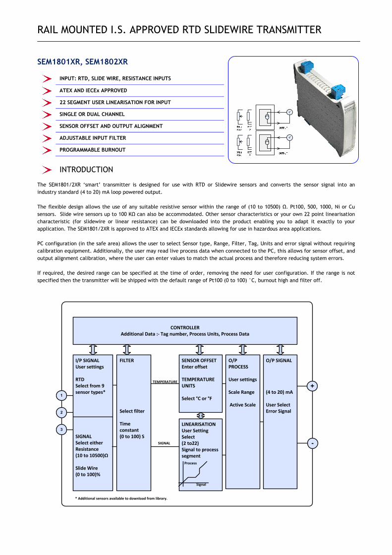
SEM1801XR, SEM1802XR
INPUT: RTD, SLIDE WIRE, RESISTANCE INPUTS
ATEX AND IECEx APPROVED
22 SEGMENT USER LINEARISATION FOR INPUT
SINGLE OR DUAL CHANNEL
SENSOR OFFSET AND OUTPUT ALIGNMENT
ADJUSTABLE INPUT FILTER
PROGRAMMABLE BURNOUT
INTRODUCTION
The SEM1801/2XR ‘smart’ transmitter is designed for use with RTD or Slidewire sensors and converts the sensor signal into an
industry standard (4 to 20) mA loop powered output.
The flexible design allows the use of any suitable resistive sensor within the range of (10 to 10500) Ω. Pt100, 500, 1000, Ni or Cu
sensors. Slide wire sensors up to 100 KΩ can also be accommodated. Other sensor characteristics or your own 22 point linearisation
characteristic (for slidewire or linear resistance) can be downloaded into the product enabling you to adapt it exactly to your
application. The SEM1801/2XR is approved to ATEX and IECEx standards allowing for use in hazardous area applications.
PC configuration (in the safe area) allows the user to select Sensor type, Range, Filter, Tag, Units and error signal without requiring
calibration equipment. Additionally, the user may read live process data when connected to the PC, this allows for sensor offset, and
output alignment calibration, where the user can enter values to match the actual process and therefore reducing system errors.
If required, the desired range can be specified at the time of order, removing the need for user configuration. If the range is not
specified then the transmitter will be shipped with the default range of Pt100 (0 to 100) °C, burnout high and filter off.
1
2
3
FILTER
Select filter
Time
constant
(0 to 100) S
O/P
PROCESS
User settings
Scale Range
Active Scale
+
-
I/P SIGNAL
User settings
RTD
Select from 9
sensor types*
SIGNAL
Select either
Resistance
(10 to 10500)Ω
Slide Wire
(0 to 100)%
CONTROLLER
Additional Data :- Tag number, Process Units, Process Data
LINEARISATION
User Setting
Select
(2 to22)
Signal to process
segment
Signal
Process
* Additional sensors available to download from library.
SENSOR OFFSET
Enter offset
TEMPERATURE
UNITS
Select °C or °F
TEMPERATURE
SIGNAL
O/P SIGNAL
(4 to 20) mA
User Select
Error Signal
RAIL MOUNTED I.S. APPROVED RTD SLIDEWIRE TRANSMITTER
Status Instruments Ltd Tel: +44 (0)1684 296818
Status Business Park Fax: +44 (0)1684 293746
Gannaway Lane, Tewkesbury Email: [email protected]
Gloucestershire, UK Website: www.status.co.uk
GL20 8FD D2559-01-02 SEM1801_2 XR CN5110 Data Sheet
SPECIFICATION @20 °C
RESISTANCE RTD INPUT Standard RTD PT100,PT500,PT1000, Cu100, Cu1000, Ni100, Ni120,
Ni1000, Cu53, library
Slide wire Pot range (1 to 100) KΩ, Signal (0 to 100) %, accuracy 0.1 %
Resistance (10 to 500) Ω ± 0.055 Ω, (500 to 2500) Ω ± 0.5 Ω, (2500 to 10500) Ω ±10.0 Ω.
Thermal Drift (0 to 500) Ω 0.013 Ω/°C, (500 to 2500) Ω 0.063 Ω/°C, (2500 to 10500) Ω 0.27 Ω/°C
Excitation current < 200 uA
Lead effect Max lead resistance 20 Ω per leg, Effect 0.002 °C / Ω
OUTPUT Type Two wire (4 to 20) mA current Loop
Range (4 to 20) mA; Upscale burnout 21.5 mA ; Downscale Burnout 3.8 mA
Accuracy (mA Out/ 2000) or 5 uA which ever is the greater, Drift 1 uA/°C
Loop Effect ± 0.2 uA/ V
Max output load [(Vsupply-10)/20] K Ohms / per channel (Example 700 Ohms @ 24 V)
SUPPLY Loop Supply (10 to 30) VDC per channel
Power < 1W Full Power per channel GENERAL Accuracy 0.2°C + (°0.05% of reading) + (sensor)
Response time Start up 5 seconds, Update 160 mS, Response 500 mS
Warm up 2 minutes.
Connections Screw terminals 2.5 mm Maximum
USER INTERFACE Type USB 2.0
Baud rate 1200 baud
Equipment PC running windows XP or later, USB configurator.
USER INTERFACE FUNCTIONS Scaling User signal to process value scaling, for simplified
setup.
Filter Adjustable time constant (0 to 100) Seconds.
User Linearisation or Profile (2 to 22) segments mV to process.
Process Units 4 Characters (signal input only)
Temperature units °C or °F
Tag Number 20 Characters
Process Output Range in process units
User offset Enter sensor offset (Temperature mode only).
Active scaling Set output process range against active sensor input
ENVIRONMENT Operating Ambient (-40 to 70) °C ; (10 to 90) %RH (non condensing)
Storage Ambient (-50 to 70) °C; (10 to 90) %RH (non condensing)
Configuration Ambient (10 to 30) °C
Installation Enclosure >= IP65.
APPROVALS CE BS EN 61326 MECHANICAL Dimensions 120 mm deep; 107 mm height; 22.5 mm wide
Weight 110 g – SEM1801XR 141 g – SEM1802XR SENSORS RTD Platinum IEC Pt100 (-200 to 850), Pt500 (-200 to 750), Pt1000 (-200 to 600) Platinum IPTS-68 Pt100 (0.00391) + Pt100 (0.00392) (-200 to 630)
Ni100 DIN 0.00618 (-60 to 180)
Ni120 0.00672 (-80 to 260)
Ni 1000 (-60 to 180)
Ni1000 Tk5000 (-50 to 150)
Ni 507.5 (-80 to 360)
Ni 604 (-200 to 200)
Cu 53 (-50 to 180)
Cu100 0.00427 (-80 to 260)
Cu1000 (-80 to 260)
Silicon KTY81-110 -120-121-122-150-210-220-221-222-250 (-55 to 175)
KTY82-110 -120-121-122-150-210-220-221-222-250 (-55 to 175)
KTY81-151,KTY82-151, KTY83-210-220-250-121-122 (-55 to 175)
KTY84-130-150 (-40 to 300)
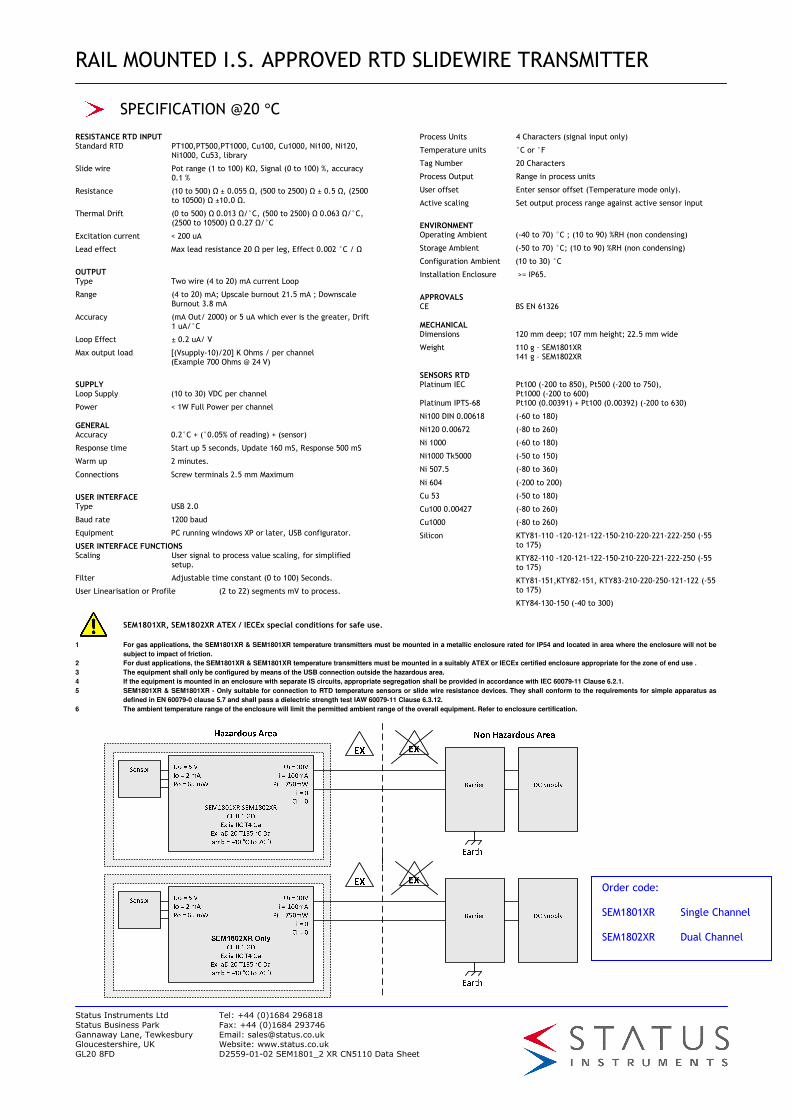
SEM1801XR, SEM1802XR ATEX / IECEx special conditions for safe use.
1 For gas applications, the SEM1801XR & SEM1801XR temperature transmitters must be mounted in a metallic enclosure rated for IP54 and located in area where the enclosure will not be
subject to impact of friction.
2 For dust applications, the SEM1801XR & SEM1801XR temperature transmitters must be mounted in a suitably ATEX or IECEx certified enclosure appropriate for the zone of end use .
3 The equipment shall only be configured by means of the USB connection outside the hazardous area.
4 If the equipment is mounted in an enclosure with separate IS circuits, appropriate segregation shall be provided in accordance with IEC 60079-11 Clause 6.2.1.
5 SEM1801XR & SEM1801XR - Only suitable for connection to RTD temperature sensors or slide wire resistance devices. They shall conform to the requirements for simple apparatus as
defined in EN 60079-0 clause 5.7 and shall pass a dielectric strength test IAW 60079-11 Clause 6.3.12.
6 The ambient temperature range of the enclosure will limit the permitted ambient range of the overall equipment. Refer to enclosure certification.
Order code: SEM1801XR Single Channel SEM1802XR Dual Channel