radiographic quality - med.cmu.ac.th004_radiographic quality... · ray and of factors affecting...
TRANSCRIPT
Radiographic Quality :Radiographic Quality :Radiographic Quality :
31 ตุลาคม 2556 08:30 - 09:30 อาคารเรียนรวม หอง 0410
ผศ. สุพจน เอื้ออภิสิทธิ์วงค หนวยเวชศาสตรนิวเคลยีรภาควชิารังสีวิทยา คณะแพทยศาสตร
มหาวิทยาลัยเชียงใหม[email protected] โทร. 053-94-6194
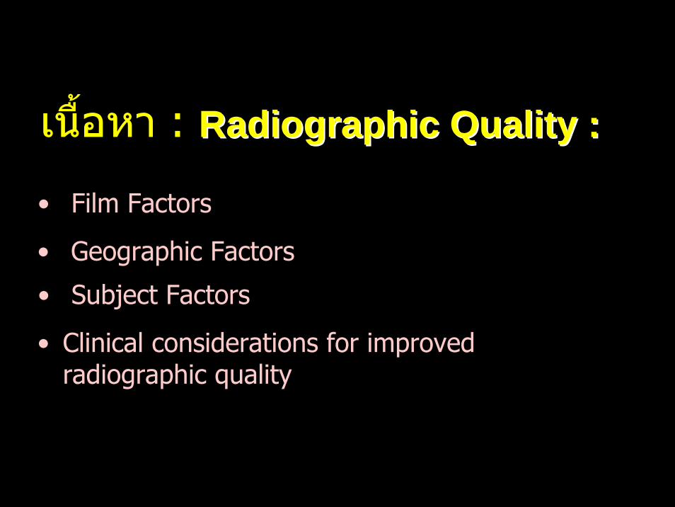
เนือ้หา : Radiographic Quality :Radiographic Quality :
• Film Factors
• Geographic Factors
• Subject Factors
• Clinical considerations for improved radiographic quality
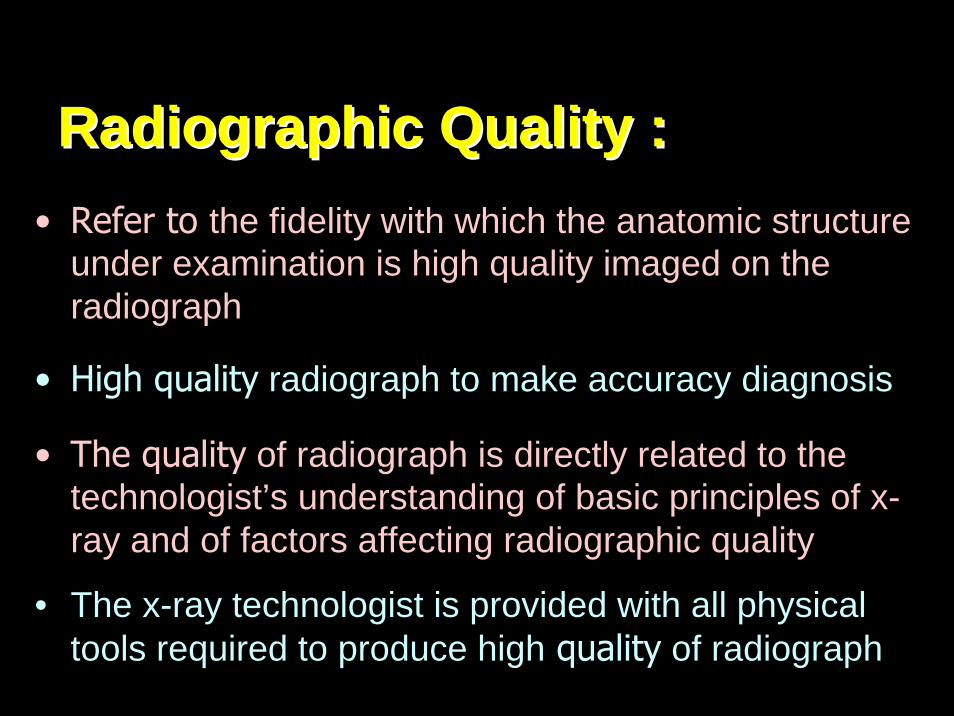
Radiographic Quality :Radiographic Quality :• Refer to the fidelity with which the anatomic structure
under examination is high quality imaged on the radiograph
• High quality radiograph to make accuracy diagnosis
• The quality of radiograph is directly related to the technologist’s understanding of basic principles of x-ray and of factors affecting radiographic quality
• The x-ray technologist is provided with all physical tools required to produce high quality of radiograph
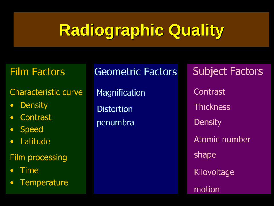
Film Factors
Characteristic curve• Density• Contrast• Speed• Latitude
Film processing• Time• Temperature
Geometric Factors
Distortion
Magnification
penumbra
Subject Factors
Contrast
Thickness
Density
Atomic number
shape
Kilovoltage
motion
Radiographic QualityRadiographic Quality
Film Factors
Characteristic curve• Density• Contrast• Speed• Latitude
Film processing• Time• Temperature
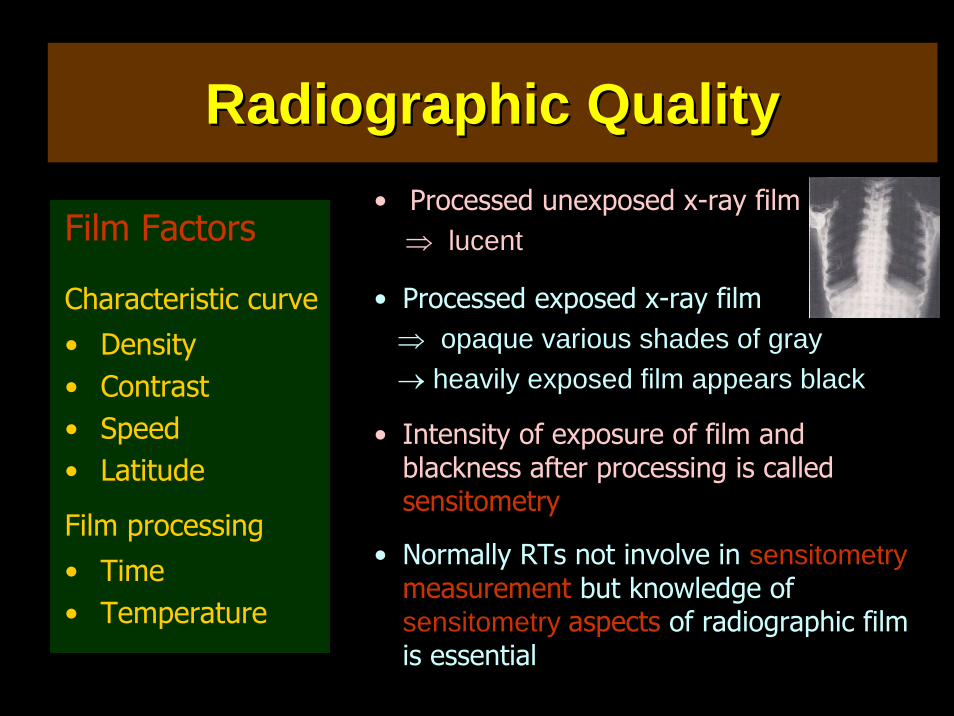
• Processed unexposed x-ray film⇒ lucent
• Processed exposed x-ray film⇒ opaque various shades of gray → heavily exposed film appears black
• Intensity of exposure of film and blackness after processing is called sensitometry
• Normally RTs not involve in sensitometrymeasurement but knowledge of sensitometry aspects of radiographic film is essential
Radiographic QualityRadiographic Quality
Radiographic QualityRadiographic Quality
Film Factors
Characteristic curve• Density• Contrast• Speed• Latitude
Film processing• Time• Temperature
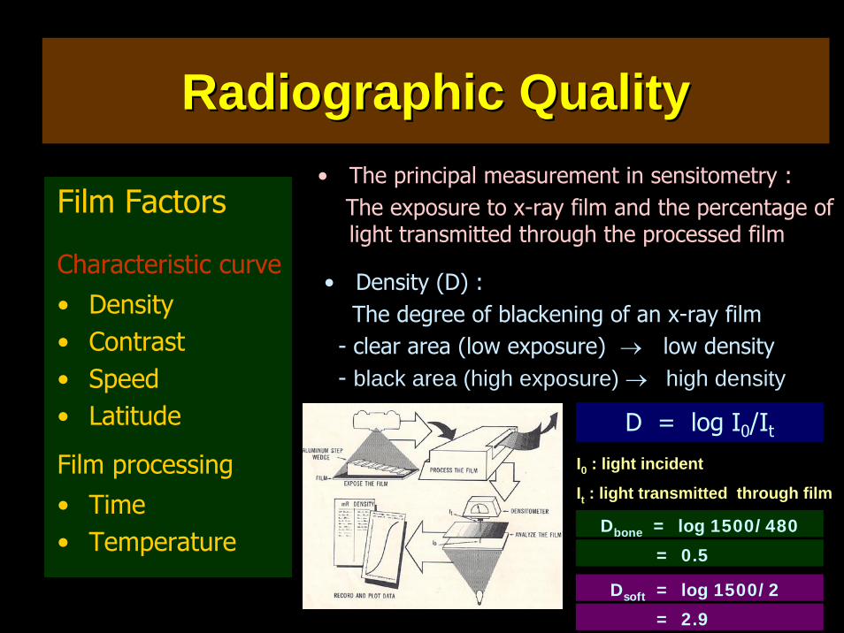
• The principal measurement in sensitometry :The exposure to x-ray film and the percentage of light transmitted through the processed film
D = log I0/It
I0 : light incident
It : light transmitted through film
• Density (D) :The degree of blackening of an x-ray film
- clear area (low exposure) → low density- black area (high exposure) → high density
Dbone = log 1500/480
Dsoft = log 1500/2
= 0.5
= 2.9
Radiographic QualityRadiographic Quality
Film Factors
Characteristic curve• Density• Contrast• Speed• Latitude
Film processing• Time• Temperature
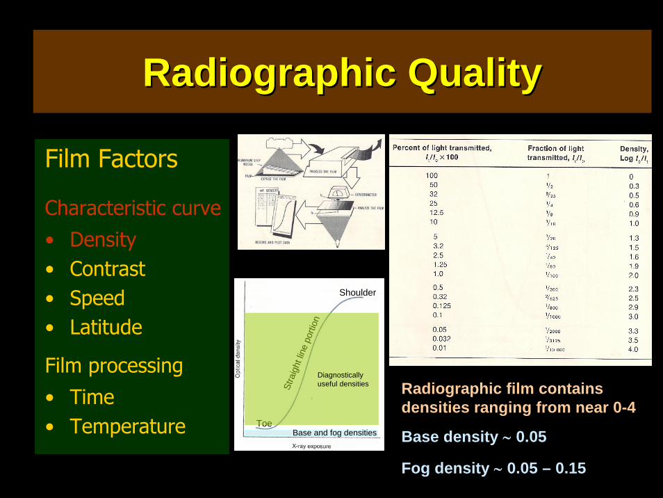
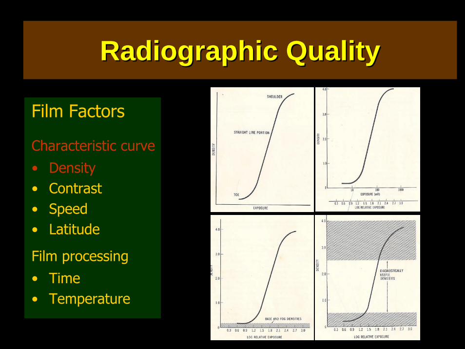
Radiographic film contains densities ranging from near 0-4
Toe
ShoulderSt
raig
ht lin
e po
rtion
Base and fog densities
Diagnostically useful densities
Base density ∼ 0.05
Fog density ∼ 0.05 – 0.15
Radiographic QualityRadiographic Quality
Film Factors
Characteristic curve• Density• Contrast• Speed• Latitude
Film processing• Time• Temperature
• The principal measurement in sensitometry :The exposure to x-ray film and the percentage of light transmitted through the processed film
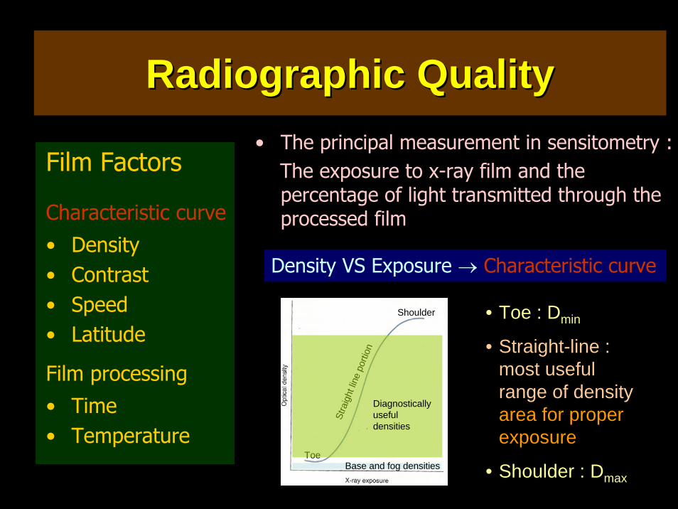
Density VS Exposure → Characteristic curve
• Toe : Dmin
• Straight-line : most useful range of density area for proper exposure
• Shoulder : Dmax
Toe
Shoulder
Stra
ight
line
porti
on
Base and fog densities
Diagnostically useful densities
Radiographic QualityRadiographic Quality
Film Factors
Characteristic curve• Density• Contrast• Speed• Latitude
Film processing• Time• Temperature
Radiographic QualityRadiographic Quality
Film Factors
Characteristic curve• Density• Contrast• Speed• Latitude
Film processing• Time• Temperature
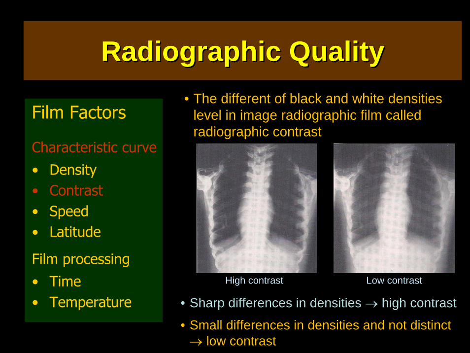
• The different of black and white densities level in image radiographic film called radiographic contrast
• Sharp differences in densities → high contrast
• Small differences in densities and not distinct → low contrast
High contrast Low contrast
Radiographic QualityRadiographic Quality
Film Factors
Characteristic curve• Density• Contrast• Speed• Latitude
Film processing• Time• Temperature
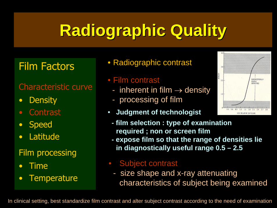
• Radiographic contrast
• Film contrast- inherent in film → density- processing of film
• Judgment of technologist- film selection : type of examination
required ; non or screen film- expose film so that the range of densities lie
in diagnostically useful range 0.5 – 2.5
• Subject contrast- size shape and x-ray attenuating
characteristics of subject being examined
In clinical setting, best standardize film contrast and alter subject contrast according to the need of examination
Radiographic QualityRadiographic Quality
Film Factors
Characteristic curve• Density• Contrast• Speed• Latitude
Film processing• Time• Temperature
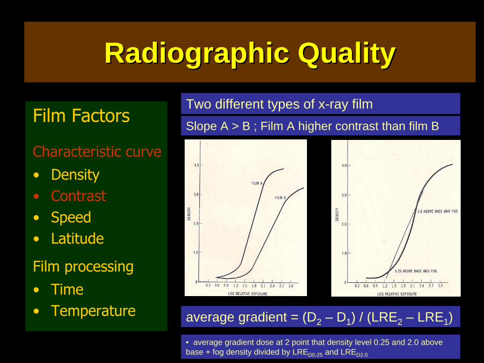
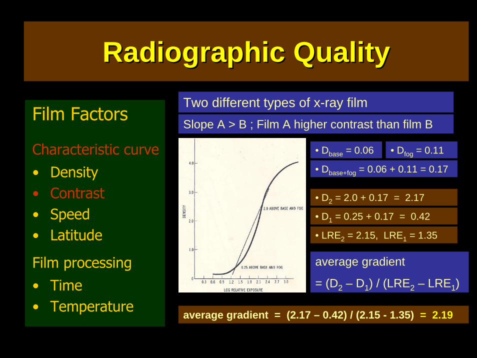
Two different types of x-ray filmSlope A > B ; Film A higher contrast than film B
average gradient = (D2 – D1) / (LRE2 – LRE1)
• average gradient dose at 2 point that density level 0.25 and 2.0 above base + fog density divided by LRED0.25 and LRED2.0
Radiographic QualityRadiographic Quality
Film Factors
Characteristic curve• Density• Contrast• Speed• Latitude
Film processing• Time• Temperature
Two different types of x-ray filmSlope A > B ; Film A higher contrast than film B
average gradient
= (D2 – D1) / (LRE2 – LRE1)
• Dbase = 0.06 • Dfog = 0.11
• Dbase+fog = 0.06 + 0.11 = 0.17
• D2 = 2.0 + 0.17 = 2.17
• D1 = 0.25 + 0.17 = 0.42
• LRE2 = 2.15, LRE1 = 1.35
average gradient = (2.17 – 0.42) / (2.15 - 1.35) = 2.19
Radiographic QualityRadiographic Quality
Film Factors
Characteristic curve• Density• Contrast• Speed• Latitude
Film processing• Time• Temperature
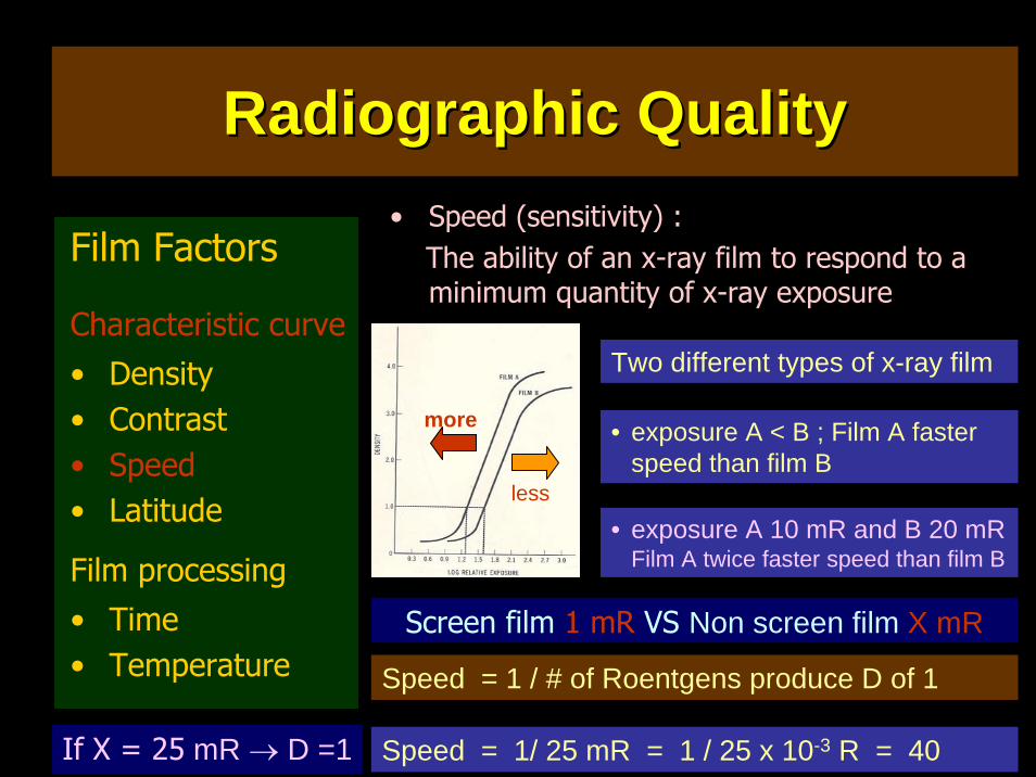
• Speed (sensitivity) :The ability of an x-ray film to respond to a minimum quantity of x-ray exposure
Screen film 1 mR VS Non screen film X mR
Speed = 1 / # of Roentgens produce D of 1
Two different types of x-ray film
• exposure A 10 mR and B 20 mRFilm A twice faster speed than film B
more
less
• exposure A < B ; Film A faster speed than film B
If X = 25 mR → D =1 Speed = 1/ 25 mR = 1 / 25 x 10-3 R = 40
Radiographic QualityRadiographic Quality
Film Factors
Characteristic curve• Density• Contrast• Speed• Latitude
Film processing• Time• Temperature
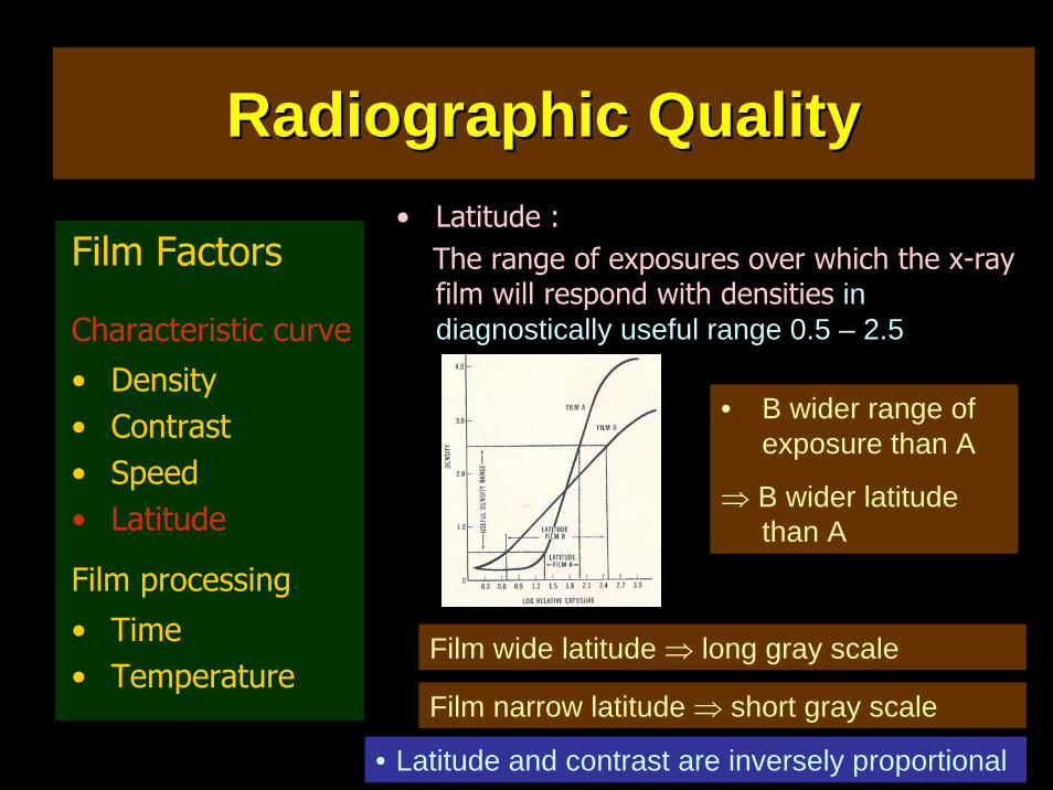
• Latitude :The range of exposures over which the x-ray film will respond with densities in diagnostically useful range 0.5 – 2.5
• B wider range of exposure than A
⇒ B wider latitude than A
Film wide latitude ⇒ long gray scale
Film narrow latitude ⇒ short gray scale
• Latitude and contrast are inversely proportional
Radiographic QualityRadiographic Quality
Film Factors
Characteristic curve• Density• Contrast• Speed• Latitude
Film processing• Time• Temperature
• Film processing :Proper film processing is required for optimum film contrast .
Film agitation during development
Composition of processing chemical
Factor affecting the degree of development
Development temperature
Development time
• Degree of development pronounced effect on the level of film fog and on the density from a giving exposure at a given film speed
Radiographic QualityRadiographic Quality
Film Factors
Characteristic curve• Density• Contrast• Speed• Latitude
Film processing• Time• Temperature
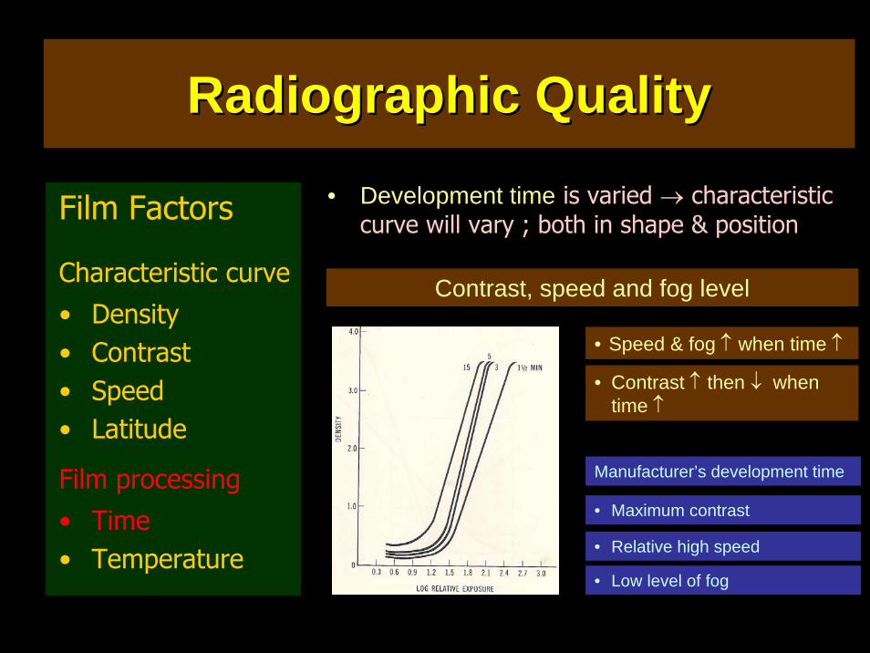
• Development time is varied → characteristic curve will vary ; both in shape & position
Contrast, speed and fog level
• Speed & fog ↑ when time ↑
• Contrast ↑ then ↓ when time ↑
Manufacturer’s development time
• Maximum contrast
• Relative high speed
• Low level of fog
Radiographic QualityRadiographic Quality
Film Factors
Characteristic curve• Density• Contrast• Speed• Latitude
Film processing• Time• Temperature
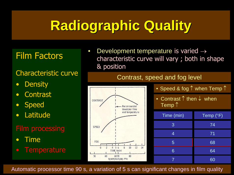
• Development temperature is varied →characteristic curve will vary ; both in shape & position
Contrast, speed and fog level
• Speed & fog ↑ when Temp ↑
• Contrast ↑ then ↓ when Temp ↑
Time (min)
3
4
5
6
7
Temp (°F)
74
71
68
64
60
Automatic processor time 90 s, a variation of 5 s can significant changes in film quality
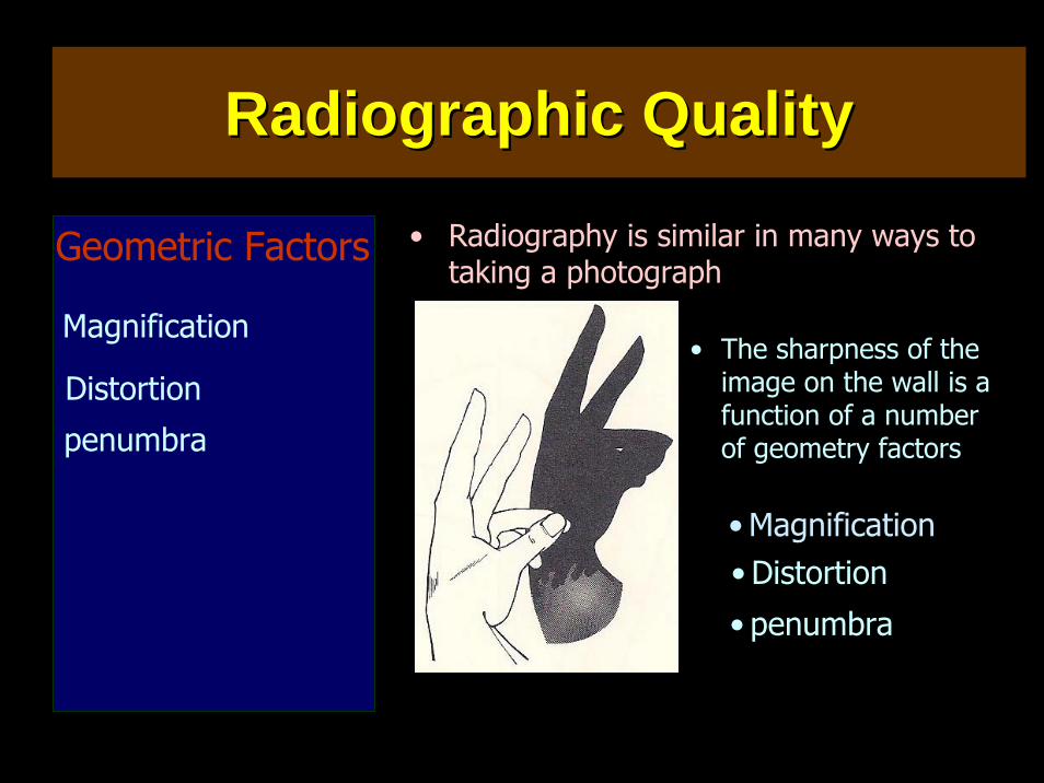
• Radiography is similar in many ways to taking a photograph
• The sharpness of the image on the wall is a function of a number of geometry factors
Geometric Factors
Distortion
Magnification
penumbra
• Distortion• Magnification
• penumbra
Radiographic QualityRadiographic Quality
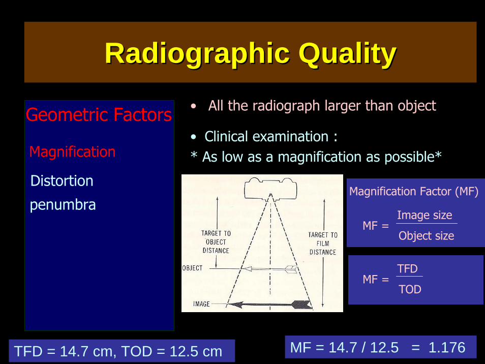
• All the radiograph larger than object
• Clinical examination :* As low as a magnification as possible*
Magnification Factor (MF)
Geometric Factors
Distortion
Magnification
penumbraMF =
Image size
Object size
MF = TFD
TOD
TFD = 14.7 cm, TOD = 12.5 cm MF = 14.7 / 12.5 = 1.176
Radiographic QualityRadiographic Quality
Geometric Factors
Distortion
Magnification
penumbra
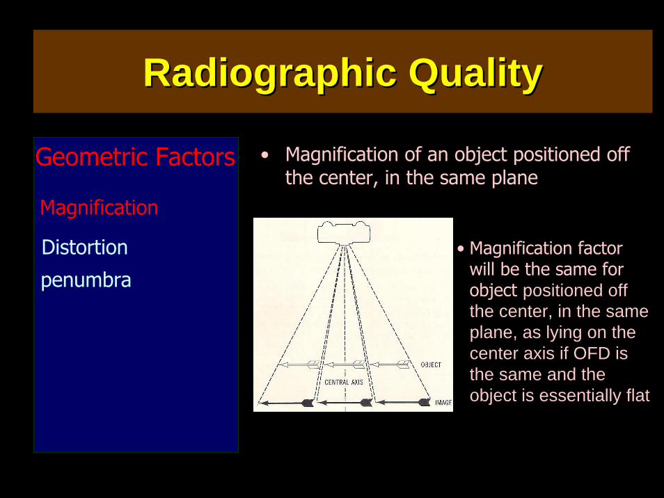
• Magnification of an object positioned off the center, in the same plane
Radiographic QualityRadiographic Quality
• Magnification factor will be the same for object positioned off the center, in the same plane, as lying on the center axis if OFD is the same and the object is essentially flat
Geometric Factors
Distortion
Magnification
penumbra
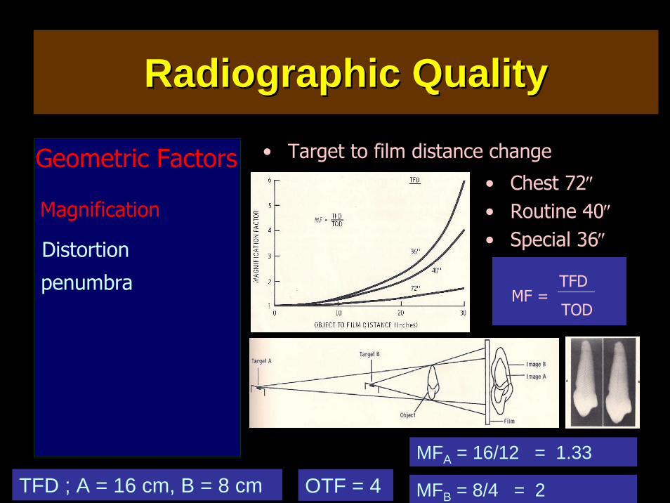
• Target to film distance change
• Chest 72″• Routine 40″• Special 36″
MF = TFD
TOD
TFD ; A = 16 cm, B = 8 cm OTF = 4MFA = 16/12 = 1.33
MFB = 8/4 = 2
Radiographic QualityRadiographic Quality
• Unequal magnification of different portion of the same object
• Distortion can hinder proper interpretation of radiograph
• Factors contribute to image distortion
Geometric Factors
Distortion
Magnification
penumbra
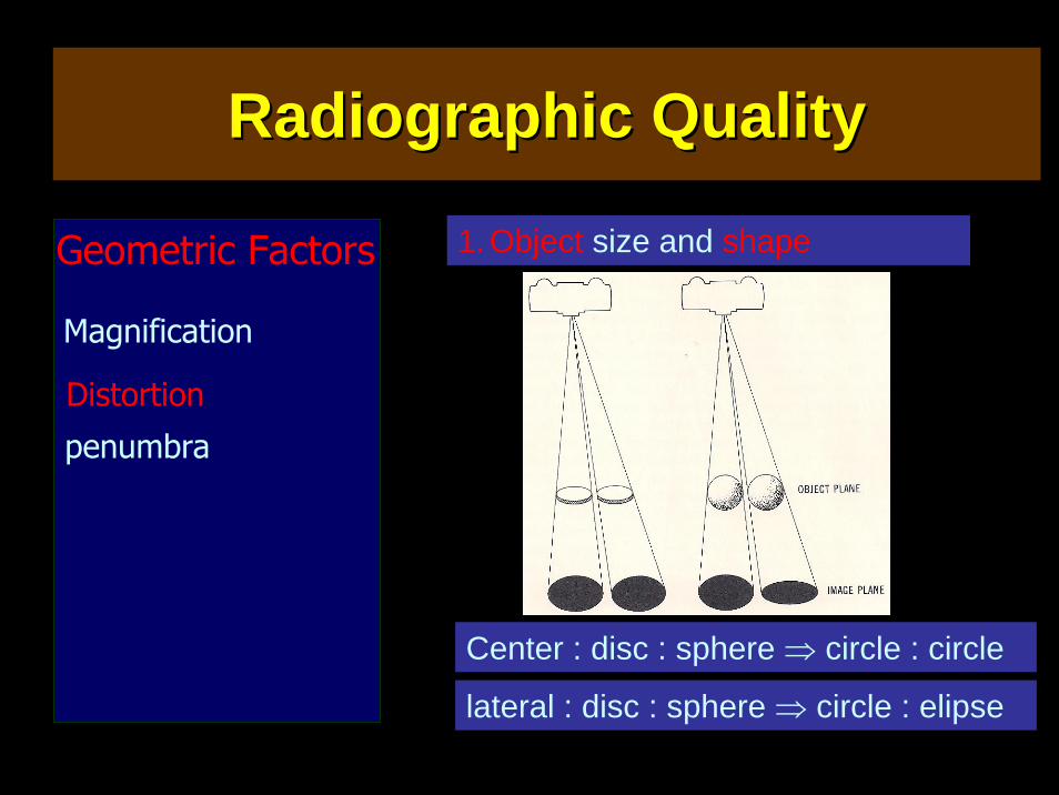
1. The size and shape of the object
2. The position of the object
Radiographic QualityRadiographic Quality
Geometric Factors
Distortion
Magnification
penumbra
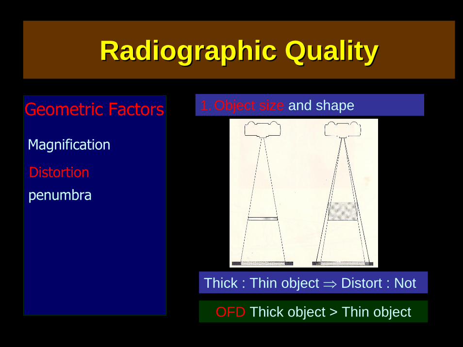
1. Object size and shape
Thick : Thin object ⇒ Distort : Not
OFD Thick object > Thin object
Radiographic QualityRadiographic Quality
Geometric Factors
Distortion
Magnification
penumbra
1. Object size and shape
Center : disc : sphere ⇒ circle : circle
lateral : disc : sphere ⇒ circle : elipse
Radiographic QualityRadiographic Quality
Geometric Factors
Distortion
Magnification
penumbra
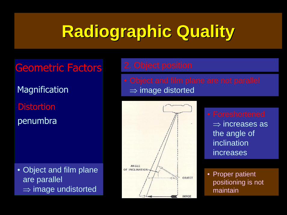
2. Object position
• Object and film plane are parallel ⇒ image undistorted
• Object and film plane are not parallel ⇒ image distorted
• Proper patient positioning is not maintain
• Foreshortened ⇒ increases as the angle of inclination increases
Radiographic QualityRadiographic Quality
Geometric Factors
Distortion
Magnification
penumbra
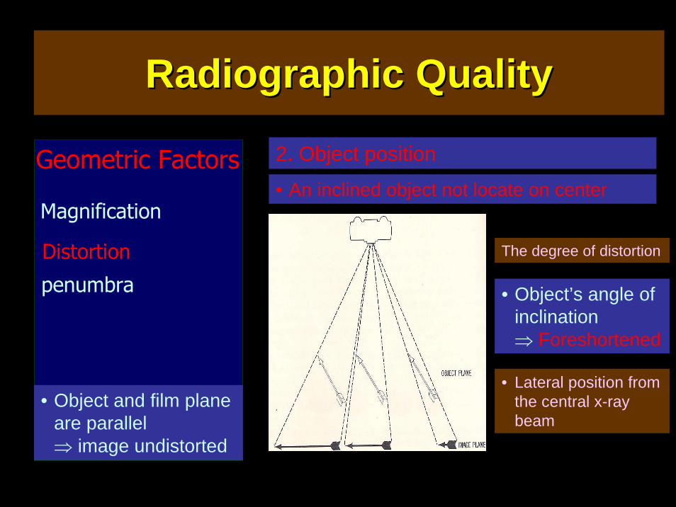
2. Object position
• Object and film plane are parallel ⇒ image undistorted
• An inclined object not locate on center
• Lateral position from the central x-ray beam
• Object’s angle of inclination ⇒ Foreshortened
The degree of distortion
Radiographic QualityRadiographic Quality
Geometric Factors
Distortion
Magnification
penumbra
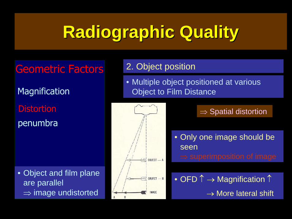
2. Object position
• Object and film plane are parallel ⇒ image undistorted
• Multiple object positioned at various Object to Film Distance
⇒ Spatial distortion
• Only one image should be seen ⇒ superimposition of image
• OFD ↑ → Magnification ↑
→ More lateral shift
Radiographic QualityRadiographic Quality
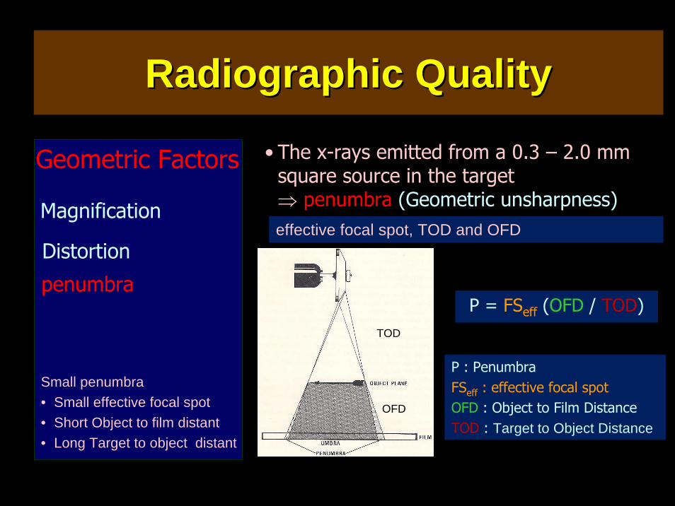
• The x-rays emitted from a 0.3 – 2.0 mm square source in the target ⇒ penumbra (Geometric unsharpness)
Geometric Factors
Distortion
Magnification
penumbra
effective focal spot, TOD and OFD
Small penumbra• Small effective focal spot• Short Object to film distant• Long Target to object distant
P = FSeff (OFD / TOD)
P : PenumbraFSeff : effective focal spotOFD : Object to Film DistanceTOD : Target to Object Distance
TOD
OFD
Radiographic QualityRadiographic Quality
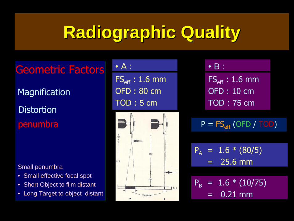
• A : Geometric Factors
Distortion
Magnification
penumbra
Small penumbra• Small effective focal spot• Short Object to film distant• Long Target to object distant
P = FSeff (OFD / TOD)
PA = 1.6 * (80/5)= 25.6 mm
TOD
OFD
FSeff : 1.6 mmOFD : 80 cmTOD : 5 cm
• B : FSeff : 1.6 mmOFD : 10 cmTOD : 75 cm
PB = 1.6 * (10/75)= 0.21 mm
Radiographic QualityRadiographic Quality
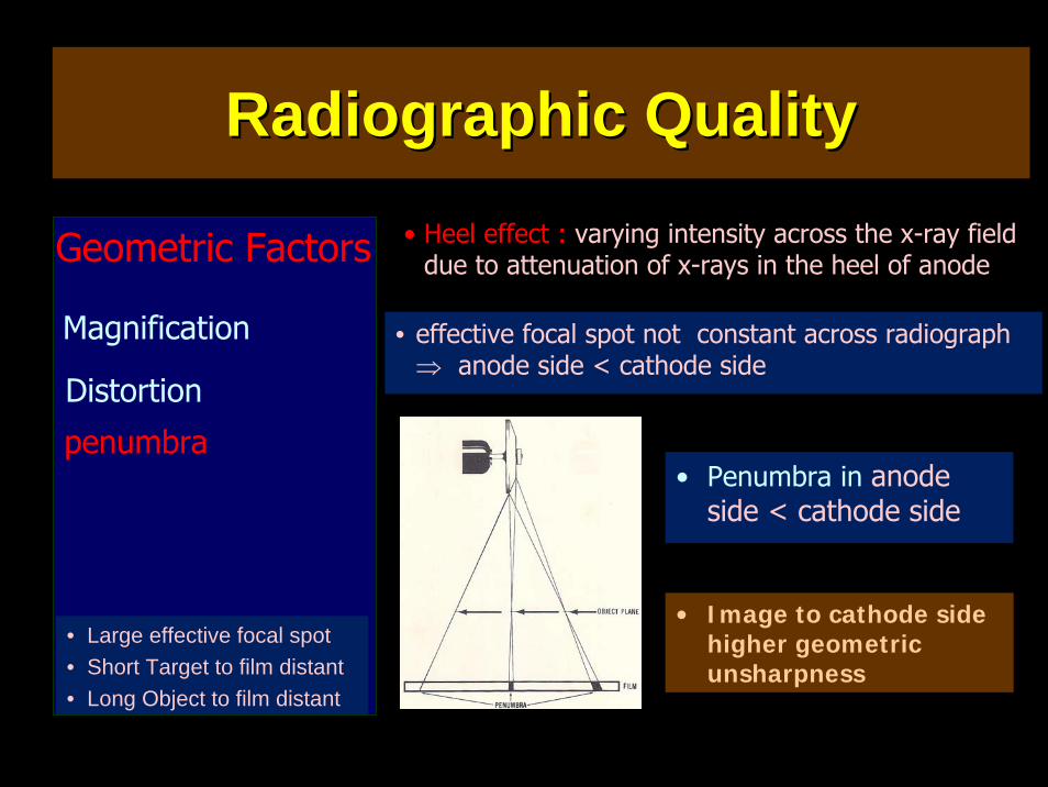
• Heel effect : varying intensity across the x-ray field due to attenuation of x-rays in the heel of anodeGeometric Factors
Distortion
Magnification
penumbra• Penumbra in anode
side < cathode side
• effective focal spot not constant across radiograph ⇒ anode side < cathode side
• Large effective focal spot• Short Target to film distant• Long Object to film distant
• Image to cathode side higher geometric unsharpness
Radiographic QualityRadiographic Quality
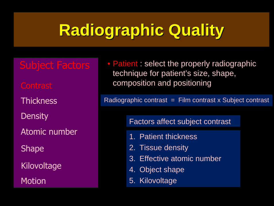
• Patient : select the properly radiographic technique for patient’s size, shape, composition and positioning
Radiographic contrast = Film contrast x Subject contrast
Factors affect subject contrast
1. Patient thickness2. Tissue density3. Effective atomic number4. Object shape5. Kilovoltage
Subject Factors
Contrast
Thickness
Density
Atomic number
Motion
Shape
Kilovoltage
Radiographic QualityRadiographic Quality
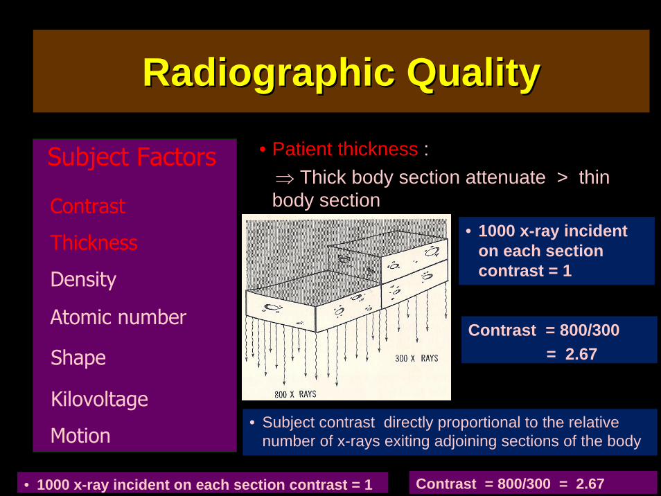
• Patient thickness :⇒ Thick body section attenuate > thin body section
• Subject contrast directly proportional to the relative number of x-rays exiting adjoining sections of the body
Subject Factors
Contrast
Thickness
Density
Atomic number
Motion
Shape
Kilovoltage
• 1000 x-ray incident on each section contrast = 1
Contrast = 800/300= 2.67
• 1000 x-ray incident on each section contrast = 1 Contrast = 800/300 = 2.67
Radiographic QualityRadiographic Quality
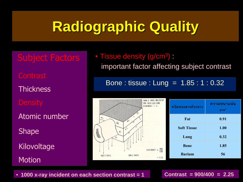
• Tissue density (g/cm3) :important factor affecting subject contrast
Bone : tissue : Lung = 1.85 : 1 : 0.32
Subject Factors
Contrast
Thickness
Density
Atomic number
Motion
Shape
Kilovoltage
ชนิดของสารตัวกลาง ความหนาแนน
g/cm3
Fat 0.91
Soft Tissue 1.00
Lung 0.32
Bone
Barium
1.85
56
• 1000 x-ray incident on each section contrast = 1 Contrast = 900/400 = 2.25
Radiographic QualityRadiographic Quality
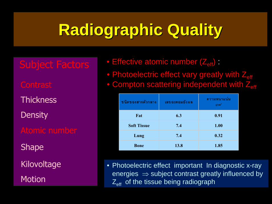
• Effective atomic number (Zeff) :• Photoelectric effect vary greatly with Zeff• Compton scattering independent with Zeff
• Photoelectric effect important In diagnostic x-ray energies ⇒ subject contrast greatly influenced by Zeff of the tissue being radiograph
ชนิดของสารตัวกลาง เลขอะตอมยังผล ความหนาแนน
g/cm3
Fat 6.3 0.91
Soft Tissue 7.4 1.00
Lung 7.4 0.32
Bone 13.8 1.85
Subject Factors
Contrast
Thickness
Density
Atomic number
Motion
Shape
Kilovoltage
Radiographic QualityRadiographic Quality
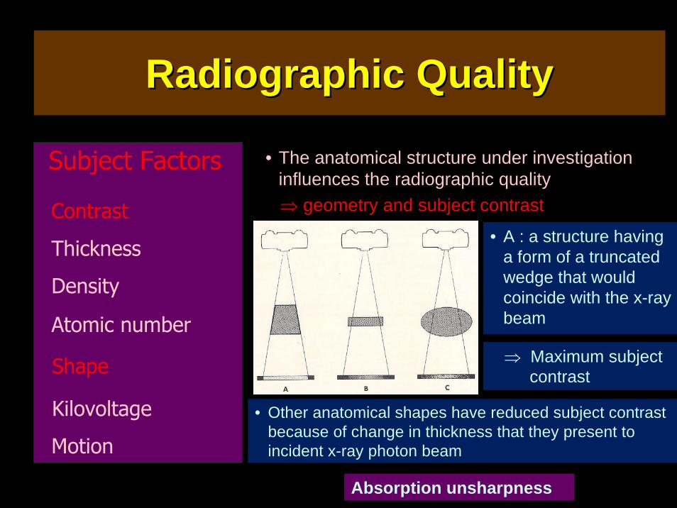
• The anatomical structure under investigation influences the radiographic quality⇒ geometry and subject contrast
• A : a structure having a form of a truncated wedge that would coincide with the x-ray beam
Subject Factors
Contrast
Thickness
Density
Atomic number
Motion
Shape
Kilovoltage
⇒ Maximum subject contrast
• Other anatomical shapes have reduced subject contrast because of change in thickness that they present to incident x-ray photon beam
Absorption unsharpness
Radiographic QualityRadiographic Quality
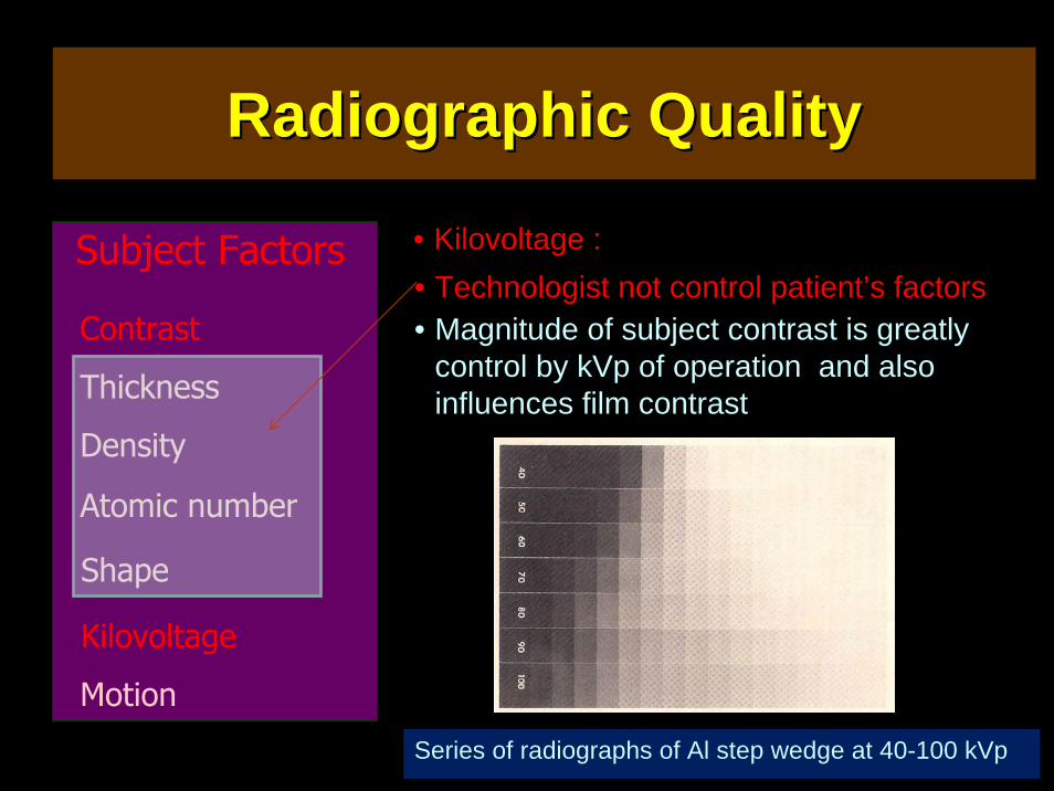
• Kilovoltage :Subject Factors
Contrast
Thickness
Density
Atomic number
Motion
Shape
Kilovoltage
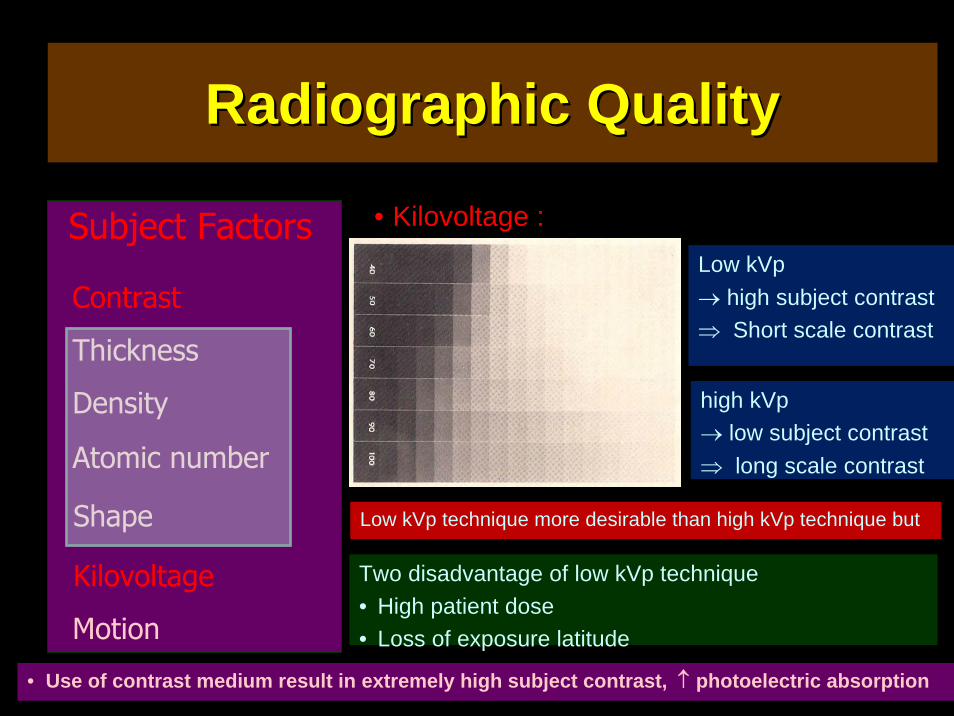
Series of radiographs of Al step wedge at 40-100 kVp
• Technologist not control patient’s factors• Magnitude of subject contrast is greatly
control by kVp of operation and also influences film contrast
Radiographic QualityRadiographic Quality
• Kilovoltage :Subject Factors
Contrast
Thickness
Density
Atomic number
Motion
Shape
Kilovoltage
Low kVp→ high subject contrast ⇒ Short scale contrast
high kVp→ low subject contrast⇒ long scale contrast
Low kVp technique more desirable than high kVp technique but
Two disadvantage of low kVp technique• High patient dose• Loss of exposure latitude
• Use of contrast medium result in extremely high subject contrast, ↑ photoelectric absorption
Radiographic QualityRadiographic Quality
• Movement of either the patient or the x-ray tube during the x-ray exposure result in blurring radiographic image⇒ loss of radiographic quality
Motion unsharpness
• Normally, motion of x-ray tube not a problem : in tomography tube move in precise geometric pattern during exposure to blur the images of structures on either side of the plane of interest
Subject Factors
Contrast
Thickness
Density
Atomic number
Motion
Shape
Kilovoltage
• Reciprocating bucky
• Cause reexamination during procedures
Radiographic QualityRadiographic Quality
• Motion unsharpness can reduce by carefully instruction the patient by x-ray technologist
• Use shortest possible exposure time• Restrict patient motion by instruction or
restraining device• Use a large TFD• Use a small OFD
Subject Factors
Contrast
Thickness
Density
Atomic number
Motion
Shape
Kilovoltage
Geometric unsharpness
• Guideline for reducing Motion unsharpness
Radiographic QualityRadiographic Quality
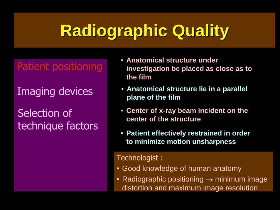
• Anatomical structure under investigation be placed as close as to the film
Patient positioning
Imaging devices
Selection of technique factors
• Anatomical structure lie in a parallel plane of the film
• Center of x-ray beam incident on the center of the structure
• Patient effectively restrained in order to minimize motion unsharpness
Technologist :• Good knowledge of human anatomy• Radiographic positioning → minimum image
distortion and maximum image resolution
Radiographic QualityRadiographic Quality
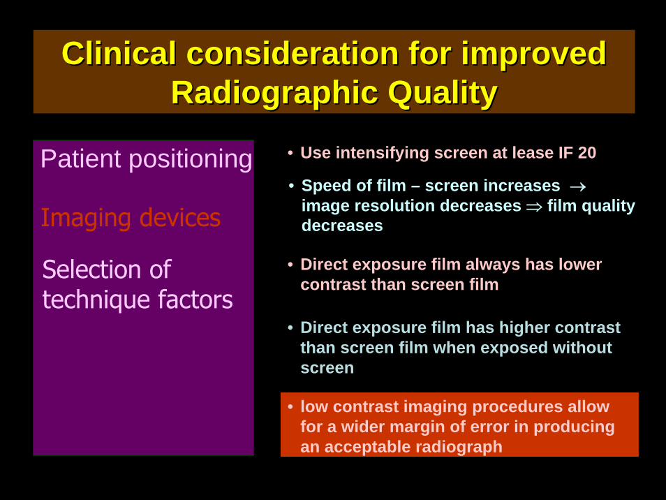
Clinical consideration for improved Clinical consideration for improved Radiographic QualityRadiographic Quality
• Use intensifying screen at lease IF 20Patient positioning
Imaging devices
Selection of technique factors
• Speed of film – screen increases →image resolution decreases ⇒ film quality decreases
• Direct exposure film always has lower contrast than screen film
• low contrast imaging procedures allow for a wider margin of error in producing an acceptable radiograph
• Direct exposure film has higher contrast than screen film when exposed without screen
Clinical consideration for improved Clinical consideration for improved Radiographic QualityRadiographic Quality
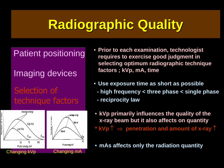
• Prior to each examination, technologist requires to exercise good judgment in selecting optimum radiographic technique factors ; kVp, mA, time
Patient positioning
Imaging devices
Selection of technique factors
• Use exposure time as short as possible- high frequency < three phase < single phase- reciprocity law
• kVp primarily influences the quality of the x-ray beam but it also affects on quantity
* kVp ↑ ⇒ penetration and amount of x-ray ↑
• mAs affects only the radiation quantityChanging mAChanging kVp
Radiographic QualityRadiographic Quality
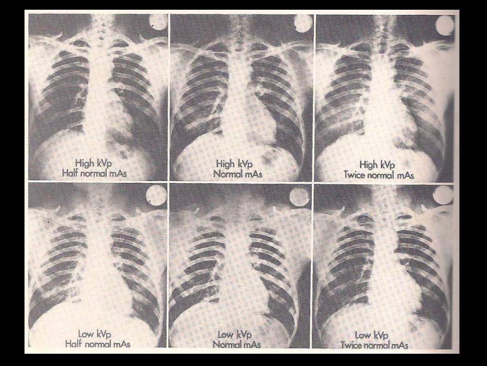
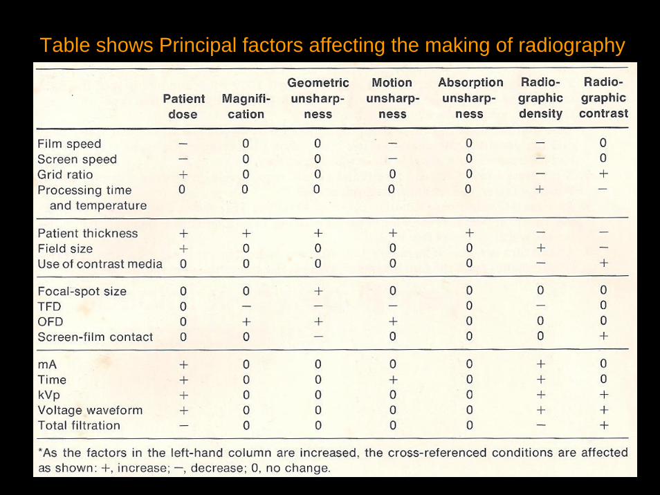
Table shows Principal factors affecting the making of radiography
หนังสอือานประกอบหนังสอือานประกอบ
Techniques of Veterinary Radiography 5th.Ed.1993.Joe P. Morgan
Radiography in Veterinary Technology.1and 2th Ed 1994,1999 Lisa M. Lavin.
Radiographic Photography and Imaging process.1980. David Jenkin
Radiation Image and Exposure. 2th Ed 2004. Terri L. Fauber.
Physics of radiology. 1993. Anthony B. Wolbarst

บันไดนาค พระธาตุดอยสุเทพ เชียงใหม