radio receiver - download.e-bookshelf.de · radio receiver technology principles, architectures and...
TRANSCRIPT


RADIO RECEIVERTECHNOLOGY


RADIO RECEIVERTECHNOLOGYPRINCIPLES, ARCHITECTURESAND APPLICATIONS
Ralf Rudersdorfer
In cooperation with
Ulrich Graf(in I.1, I.2, II.8.1, III.9, IV.5, V.2.3, V.3)
Hans Zahnd(in I.2.3, I.3, III.6.1, III.9.5)
Translated by Gerhard K. Buesching, E. Eng.

This edition first published 2014© 2014 Ralf Rudersdorfer
Authorised Translation in extended and international adapted form from the German language edition publishedby Elektor Verlag © 2010.
Registered officeJohn Wiley & Sons Ltd, The Atrium, Southern Gate, Chichester, West Sussex, PO19 8SQ, United Kingdom
For details of our global editorial offices, for customer services and for information about how to apply forpermission to reuse the copyright material in this book please see our website at www.wiley.com.
The right of the author to be identified as the author of this work has been asserted in accordance with theCopyright, Designs and Patents Act 1988.
All rights reserved. No part of this publication may be reproduced, stored in a retrieval system, or transmitted, inany form or by any means, electronic, mechanical, photocopying, recording or otherwise, except as permitted bythe UK Copyright, Designs and Patents Act 1988, without the prior permission of the publisher.
Wiley also publishes its books in a variety of electronic formats. Some content that appears in print may not beavailable in electronic books.
Designations used by companies to distinguish their products are often claimed as trademarks. All brand namesand product names used in this book are trade names, service marks, trademarks or registered trademarks of theirrespective owners. The publisher is not associated with any product or vendor mentioned in this book. Thispublication is designed to provide accurate and authoritative information in regard to the subject matter covered.It is sold on the understanding that the publisher is not engaged in rendering professional services. If professionaladvice or other expert assistance is required, the services of a competent professional should be sought.
Library of Congress Cataloging-in-Publication Data
Rudersdorfer, Ralf.[Funkempfangerkompendium. English]Radio receiver technology : principles, architectures, and applications / Ralf Rudersdorfer, Ulrich Graf,
Hans Zahnd.pages cm
Translation of: Funkempfangerkompendium.Includes bibliographical references and index.
ISBN 978-1-118-50320-1 (hardback)1. Radio–Receivers and reception. I. Graf, Ulrich, 1948- II. Zahnd, Hans. III. Title.
TK6563.R6813 2013621.3841′8–dc23
2013008682
A catalogue record for this book is available from the British Library.
ISBN: 9781118503201
Set in 10/12 Times by Laserwords Private Limited, Chennai, India
1 2014

Contents
About the Author xi
Preface xiii
Acknowledgements xv
I Functional Principle of Radio Receivers 1
I.1 Some History to Start 1I.1.1 Resonance Receivers, Fritters, Coherers, and Square-Law
Detectors (Detector Receivers) 1I.1.2 Development of the Audion 2
I.2 Present-Day Concepts 4I.2.1 Single-Conversion Superhet 4I.2.2 Multiple-Conversion Superhet 8I.2.3 Direct Mixer 14I.2.4 Digital Receiver 17
I.3 Practical Example of an (All-)Digital Radio Receiver 23I.3.1 Functional Blocks for Digital Signal Processing 25I.3.2 The A/D Converter as a Key Component 26I.3.3 Conversion to Zero Frequency 30I.3.4 Accuracy and Reproducibility 33I.3.5 VFO for Frequency Tuning 34I.3.6 Other Required Hardware 36I.3.7 Receive Frequency Expansion by Subsampling 37
I.4 Practical Example of a Portable Wideband Radio Receiver 39I.4.1 Analog RF Frontend for a Wide Receive Frequency Range 40I.4.2 Subsequent Digital Signal Processing 42I.4.3 Demodulation with Received Signal Level Measurement 43I.4.4 Spectral Resolution of the Frequency Occupancy 45
References 46Further Reading 48

vi Contents
II Fields of Use and Applications of Radio Receivers 49
II.1 Prologue 49II.2 Wireless Telecontrol 50
II.2.1 Radio Ripple Control 52II.3 Non-Public Radio Services 54
II.3.1 Air Traffic Radio 54II.3.2 Maritime Radio 56II.3.3 Land Radio 58II.3.4 Amateur Radio 60II.3.5 Mobile Radio 63
II.4 Radio Intelligence, Radio Surveillance 64II.4.1 Numerous Signal Types 64II.4.2 Searching and Detecting 69II.4.3 Monitoring Emissions 75II.4.4 Classifying and Analyzing Radio Scenarios 78II.4.5 Receiver Versus Spectrum Analyzer 81
II.5 Direction Finding and Radio Localization 83II.5.1 Basic Principles of Radio Direction Finding 83II.5.2 Radio Reconnaissance and Radio Surveillance 94II.5.3 Aeronautical Navigation and Air Traffic Control 98II.5.4 Marine Navigation and Maritime Traffic 100
II.6 Terrestrial Radio Broadcast Reception 101II.7 Time Signal Reception 104II.8 Modern Radio Frequency Usage and Frequency Economy 107
II.8.1 Trunked Radio Networks 107II.8.2 Cognitive Radio 108
References 109Further Reading 112
III Receiver Characteristics and their Measurement 113
III.1 Objectives and Benefits 113III.2 Preparations for Metrological Investigations 114
III.2.1 The Special Case of Correlative Noise Suppression 115III.2.2 The Special Case of Digital Radio Standards 116
III.3 Receiver Input Matching and Input Impedance 118III.3.1 Measuring Impedance and Matching 120III.3.2 Measuring Problems 121
III.4 Sensitivity 121III.4.1 Limitations Set by Physics 122III.4.2 Noise Factor and Noise Figure 123III.4.3 Measuring the Noise Figure 125III.4.4 Equivalent Noise Bandwidth 127III.4.5 Minimum Discernible Signal 129III.4.6 Measuring the Minimum Discernible Signal 130III.4.7 Input Noise Voltage 131

Contents vii
III.4.8 Signal-to-Interference Ratio (SIR) and Operational Sensitivity(S+N)/N, SINAD 132
III.4.9 De-emphasis 136III.4.10 Usable and Suitable Sensitivity 138III.4.11 Maximum Signal-to-Interference Ratio 144III.4.12 Measuring the Operational Sensitivity and Maximum SIR 145III.4.13 Measuring Problems 147
III.5 Spurious Reception 147III.5.1 Origin of Inherent Spurious Response 147III.5.2 Measuring Inherent Spurious Response 148III.5.3 Reception and Suppression of Image Frequencies 149III.5.4 IF Interference and IF Interference Ratio 151III.5.5 Reception of Other Interfering Signals 152III.5.6 Measuring the Spurious Signal Reception 153III.5.7 The Special Case of Linear Crosstalk 153III.5.8 Measuring the Linear Crosstalk Suppression 154III.5.9 Measuring Problems 155
III.6 Near Selectivity 156III.6.1 Receive Bandwidth and Shape Factor 157III.6.2 Measuring the Receive Bandwidth 158III.6.3 Adjacent Channel Suppression 160III.6.4 Measuring the Adjacent Channel Suppression 160III.6.5 Measuring Problems 161
III.7 Reciprocal Mixing 162III.7.1 Single Sideband Noise 162III.7.2 Non-Harmonic (Close to Carrier) Distortions 166III.7.3 Sensitivity Reduction by Reciprocal Mixing 166III.7.4 Measuring Reciprocal Mixing 169III.7.5 Measuring Problems 171
III.8 Blocking 171III.8.1 Compression in the RF Frontend or the IF Section 171III.8.2 AGC Response to Interfering Signals 172III.8.3 Reduction of Signal-to-Interference Ratio by Blocking 172III.8.4 Measuring the Blocking Effect 173III.8.5 Measuring Problems 174
III.9 Intermodulation 174III.9.1 Origin of Intermodulation 174III.9.2 Second-and Third-Order Intermodulation 175III.9.3 Higher Order Intermodulation 181III.9.4 The Special Case of Electromechanical, Ceramic
and Quartz Filters 182III.9.5 The Special Case of A/D Converted and Digitally
Processed Signals 183III.9.6 Intermodulation Immunity 185III.9.7 Maximum Intermodulation-Limited Dynamic Range 185III.9.8 Intercept Point 186

viii Contents
III.9.9 Effective Intercept Point (Receiver Factor or . . .) 187III.9.10 Measuring the Intermodulation Immunity 188III.9.11 Measuring Problems 190III.9.12 In-band Intermodulation and Non-Linear Crosstalk 195III.9.13 Measurement of the In-band Intermodulation 198
III.10 Cross-Modulation 199III.10.1 Generation 199III.10.2 Ionospheric Cross-Modulation 201III.10.3 Measuring the Cross-Modulation Immunity 203III.10.4 Measuring Problems 204
III.11 Quality Factor of Selective RF Preselectors under Operating Conditions 204III.11.1 Increasing the Dynamic Range by High-Quality Preselection 205III.11.2 Measuring the Frequency Response 207
III.12 Large-Signal Behaviour in General 209III.12.1 Concrete Example 209III.12.2 The IP3 Interpretation Fallacy 212
III.13 Audio Reproduction Properties 213III.13.1 AF Frequency Response 213III.13.2 Measuring the AF Frequency Response 214III.13.3 Reproduction Quality and Distortions 214III.13.4 Measuring the Demodulation Harmonic Distortion 217III.13.5 Measuring Problems 218
III.14 Behaviour of the Automatic Gain Control (AGC) 218III.14.1 Static Control Behaviour 218III.14.2 Measuring the Static Control Behaviour 219III.14.3 Time-Dynamic Control Behaviour 219III.14.4 Measuring the Time-Dynamic Control Behaviour 221
III.15 Long-Term Frequency Stability 223III.15.1 Measuring the Long-Term Frequency Stability 224III.15.2 Measuring Problems 225
III.16 Characteristics of the Noise Squelch 226III.16.1 Measuring the Squelch Threshold 227
III.17 Receiver Stray Radiation 227III.17.1 Measuring the Receiver Stray Radiation 229III.17.2 Measuring Problems 230
III.18 (Relative) Receive Signal Strength and S Units 230III.18.1 Definitions and Predetermined Levels of S Units 233III.18.2 Measuring the Accuracy of the Relative Signal Strength Indication 234III.18.3 Measuring Problems 234
III.19 AM Suppression in the F3E Receiving Path 236III.19.1 Measuring the AM Suppression 237
III.20 Scanning Speed in Search Mode 238III.20.1 Measuring the Scanning Speed 239
References 240Further Reading 242

Contents ix
IV Practical Evaluation of Radio Receivers (A Model) 245
IV.1 Factual Situation 245IV.2 Objective Evaluation of Characteristics in Practical Operation 245
IV.2.1 Hardly Equal Conditions 247IV.2.2 No Approximation Possible 247
IV.3 Information Gained in Practical Operation 249IV.3.1 Help of a Reference Unit 252IV.3.2 A Fine Distinction is Hardly Possible or Necessary 253
IV.4 Interpretation (and Contents of the ‘Table of operational PRACTICE ’) 253IV.4.1 The Gain in Information 254
IV.5 Specific Equipment Details 255References 255Further Reading 255
V Concluding Information 257
V.1 Cascade of Noisy Two-Ports (Overall Noise Performance) 257V.2 Cascade of Intermodulating Two-Ports (Overall Intermodulation
Performance) 260V.2.1 Overall Third-Order Intercept Point 261V.2.2 Overall Second-Order Intercept Point 262V.2.3 Computer-Aided Calculations 263
V.3 Mathematical Description of the Intermodulation Formation 264V.3.1 Second-Order Intermodulation 265V.3.2 Third-Order Intermodulation 266V.3.3 Other Terms in the Transfer Characteristic Polynomial 267
V.4 Mixing and Derivation of Spurious Reception 269V.4.1 Mixing = Multiplication 269V.4.2 Ambiguous Mixing Process 271
V.5 Characteristics of Emission Classes According to the ITU RR 272V.6 Geographic Division of the Earth by Region According to ITU RR 272V.7 Conversion of dB. . . Levels 272
V.7.1 Voltage, Current and Power Levels 276V.7.2 Electric and Magnetic Field Strength, (Power) Flux
Density Levels 278References 278Further Reading 279
List of Tables 281
Index 283


About the Author
Ralf Rudersdorfer, born in 1979, began his career at the Institutefor Applied Physics. He then changed to the Institute for Com-munications Engineering and RF-Systems (formerly Institute forCommunications and Information Engineering) of the JohannesKepler University Linz, Austria, where he is head of DomainLabs and Technics. His activities included the setting up of ameasuring station with attenuated reflection properties/antennameasuring lab and furnishing the electronic labs of the Mecha-tronics Department with new basic equipment.
He began publishing technical papers at the age of 21. In August2002 he became a Guest Consultant for laboratory equipment
and RF hardware and conducted practical training courses in ‘Electronic Circuit Engi-neering’ at the reactivated Institute for Electronics Engineering at the Friedrich AlexanderUniversity Erlangen-Nuremberg, Germany. In 2006 he applied for a patent covering theutilization of a specific antenna design for two widely deviating ranges of operating fre-quencies, which was granted within only 14 months without any prior objections. Inthe winter semesters 2008 to 2011 the Johannes Kepler University Linz, Austria, com-missioned him with the execution of the practical training course on ‘Applied ElectricalEngineering’.
Rudersdorfer is the author of numerous practice-oriented publications in the fields ofradio transmitters and radio receivers, high-frequency technology, and general electron-ics. Furthermore, he was responsible for the preparation of more than 55 measuringprotocols regarding the comprehensive testing of transmitting and receiving equipmentof various designs and radio standards issued and published by a trade magazine. Dur-ing this project alone he defined more than 550 intercept points at receivers. He hasrepeatedly been invited to present papers at conferences and specialized trade fairs. Atthe same time he is active in counseling various organizations like external cooperationpartners of the university institute, public authorities, companies, associations, and edi-torial offices on wireless telecommunication, radio technology, antenna technology, andelectronic measuring systems.

xii About the Author
In the do-it-yourself competition at the VHF Convention Weinheim, Germany, in 2003he received the Young Talent Special Award in the radio technology section. At theshort-wave/VHF/UHF conference conducted in 2006 at the Munich University of AppliedSciences, Germany, he took first place in the measuring technology section. The argu-mentation for the present work in its original version received the EEEfCOM InnovationAward 2011 as a special recognition of achievements in Electrical and Electronic Engi-neering for Communication. Already at the age of 17 Ralf Rudersdorfer was active as alicensed radio amateur, which may be regarded as the cornerstone of his present interests.
Owing to his collaboration with industry and typical users of high-end radio receivers andto his work with students, the author is well acquainted with today’s technical problems.His clear and illustrative presentation of the subject of radio receivers reflects his vasthands-on experience.

Preface
The wish to receive electromagnetic waves and recover the inherent message content is asold as radio engineering itself. The progress made in technical developments and circuitintegration with regard to receiver systems enables us today to solve receiver technologyproblems with a high degree of flexibility. The increasing digitization, which shifts theanalog/digital conversion interface ever closer to the receiving antenna, further enhancesthe innovative character. Therefore, the time has come to present a survey of professionaland semi-professional receiver technologies.
The purpose of this book is to provide the users of radio receivers with the required knowl-edge of the basic mechanisms and principles of present-day receiver technology. Part Ipresents realization concepts on the system level (block diagrams) tailored to the needs ofthe different users. Circuit details are outlined only when required for comprehension. Anexception is made for the latest state-of-the-art design, the (fully) digitized radio receiver.It is described in more detail, since today’s literature contains little information about itspractical realization in a compact form.
The subsequent sections of the book deal with radio receivers as basically two-portdevices, showing the fields of application with their typical requirements. Also coveredin detail are the areas of radio receiver usage which are continuously developed and per-fected with great effort but rarely presented in publications. These are (besides modernradio direction finding and the classical radio services) predominantly sovereign radiosurveillance and radio intelligence. At the same time, they represent areas where particu-larly sophisticated radio receivers are used. This is demonstrated by the many examplesof terrestrial applications shown in Part II.
A particular challenge in the preparation of the book was the systematic presentation ofall characteristic details in order to comprehend, understand and evaluate the respectiveequipment properties and behaviour. Parts III and IV, devoted to this task, for the first timelist all receiver parameters in a comprehensive, but easy to grasp form. The descriptionconsistently follows the same sequence: Physical effect or explanation of the respectiveparameter, its acquisition by measuring techniques, and the problems that may occurduring measurement. This is followed by comments about its actual practical importance.The measuring techniques described result from experience gained in extensive laboratorywork and in practical tests. Entirely new territory in the professional literature is entered

xiv Preface
in Part IV with the model for an evaluation of practical operation and the related narrowmargin of interpretation.
The Appendix contains valuable information on the dimensioning of receiving systemsand the mathematical derivation of non-linear effects, as well as on signal mixing andsecondary reception. Furthermore, the Concluding Information provides a useful methodfor converting different level specifications as often encountered in the field of radioreceivers.
Easy comprehension and reproducibility in practice were the main objectives in the prepa-ration of the book. Many pictorial presentations were newly conceived, and the equationsintroduced were supplemented with practical calculations.
In this way the present book was compiled over many years and introduces the readerwith a basic knowledge of telecommunication to the complex matter. All technical termsused in the book are thoroughly explained and synonyms given that may be found inthe relevant literature. Where specific terms reappear in different sections, a reference ismade to the section containing the explanation. Due to the many details outlined in thetext the book is well suited as a reference work, even for the specialist. This is reinforcedby the index, with more than 1,200 entries, freely after the motto:
When the expert (developer) finds the answer to his story,spirits rise in the laboratory,
and so one works right through the nightinstead of only sleeping tight!

Acknowledgements
The professional and technically sound compilation of a specialized text always requiresa broad basis of experience and knowledge and must be approached from various view-points. Comments from specialists with many years of practical work in the relevant fieldwere therefore particularly helpful.
My special thanks go to the electrical engineers Harald Wickenhauser of Rohde&SchwarzMunich, Germany, Hans Zahnd, of the Hans Zahnd engineering consultants in Emmen-matt, Switzerland, and Ulrich Graf, formerly with Thales Electron Devices, Ulm,Germany, for their many contributions, long hours of constructive discussions andreadiness to review those parts of the manuscript that deal with their field of expertise.Furthermore, I wish to thank Dr. Markus Pichler, LCM Linz an der Donau, Austria,for his suggestions regarding mathematical expressions and notations which werecharacterized by his remarkable accuracy and willingness to share his knowledge.Thanks also go to Erwin Schimback, LCM Linz an der Donau, Austria, for unravelingthe mysteries of sophisticated electronic data processing, and to former Court CounsellorHans-Otto Modler, previously a member of the Austrian Federal Police Directorate inVienna, Austria, for proofreading the entire initial German manuscript.
I want to thank the electrical engineer Gerhard K. Busching, MEDI-translat, Neunkirchen,Germany, for his readiness to agree to many changes and his patience in incorporatingthese, his acceptance of the transfer of numerous contextual specifics, enabling an efficientcollaboration in a cooperative translation on the way to the international edition of thisbook. My thanks are also due to Dr. John McMinn, TSCTRANS, Bamberg, Germany,for the critical review of the English manuscript from a linguistic point of view.
My particular gratitude shall be expressed to the mentors of my early beginnings: OfficialCouncellor Eng. Alfred Nimmervoll and Professor Dr. Dr. h.c. Dieter Bauerle, both of theJohannes Kepler University Linz, Austria, as well as to Professor Dr. Eng. Dr. Eng. habil.Robert Weigel of the Friedrich Alexander University Erlangen-Nuremberg, Germany, fortheir continued support and confidence and their guidance, which helped inspire mymotivation and love for (radio) technology.
I wish to especially recognize all those persons in my environment, for whom I could notalways find (enough) time during the compilation of the book.

xvi Acknowledgements
Finally, not forgotten are the various companies, institutes and individuals who providedphotographs to further illustrate the book.
May the users of the book derive the expected benefits and successes in their dedicatedwork. I hope they will make new discoveries and have many ‘aha’ moments while read-ing or consulting the book. I want to thank them in advance for possible suggestions,constructive notes and feedback.
Ralf RudersdorferEnnsdorf, autumn 2013

IFunctional Principle of RadioReceivers
I.1 Some History to Start
Around 1888 the physicist Heinrich Hertz experimentally verified the existence ofelectromagnetic waves and Maxwell’s theory. At the time his transmitting systemconsisted of a spark oscillator serving as a high frequency generator to feed a dipoleof metal plates. Hertz could recognize the energy emitted by the dipole in the form ofsparks across a short spark gap connected to a circular receiving resonator that waslocated at some distance. However, this rather simple receiver system could not be usedcommercially.
I.1.1 Resonance Receivers, Fritters, Coherers, and Square-LawDetectors (Detector Receivers)
The road to commercial applications opened only after the Frenchman Branly was able todetect the received high-frequency signal by means of a coherer, also known as a fritter.His coherer consisted of a tube filled with iron filings and connected to two electrodes. Thetransfer resistance of this setup decreased with incoming high-frequency pulses, producinga crackling sound in the earphones. When this occurred the iron filings were rearrangedin a low-resistance pattern and thus insensitive to further stimulation. To keep them activeand maintain high resistance they needed to be subjected to a shaking movement. Thismechanical shaking could be produced by a device called a Wagner hammer or knocker.A receiving system comprising of a dipole antenna, a coherer as a detector, a Wagnerhammer with direct voltage source and a telephone handset formed the basis for Marconito make radio technology successful world-wide in the 1890s.
The components of this receiver system had to be modified to meet the demands ofwider transmission ranges and higher reliability. An increase in the range was achievedby replacing the simple resonator or dipole by the Marconi antenna. This featured a highvertical radiator as an isolated structure or an expanded fan- or basket-shaped antenna
Radio Receiver Technology: Principles, Architectures and Applications, First Edition. Ralf Rudersdorfer.© 2014 Ralf Rudersdorfer. Published 2014 by John Wiley & Sons, Ltd.

2 Radio Receiver Technology
VRX
fRX VAF
Selection Demodulator
Figure I.1 Functional blocks of the detector receiver. The demodulator circuit shown separatelyrepresents the actual detector. With the usually weak signals received the kink in the characteristiccurve of the demodulator diode is not very pronounced compared to the signal amplitude. Thedetector therefore has a nonlinear characteristic. It is also known as a square-law detector. (Thechoke blocks the remaining RF voltage. In the simplest versions it is omitted entirely.)
of individual wires with a ground connection. The connection to ground as a ‘returnconductor’ had already been used in times of wire-based telegraphy.
The selectivity which, until then, was determined by the resonant length of the antenna,was optimized by oscillating circuits tuned by means of either variable coils or variablecapacitors. At the beginning of the last century a discovery was made regarding therectifying effect that occurs when scanning the surface of certain elements with a metalpin. This kind of detector often used a galena crystal and eventually replaced the coherer.For a long while it became an inherent part of the detector receiver used by our great-grandparents (Fig. I.1).
The rapid growth of wireless data transmission resulted in further development of receiv-ing systems. Especially, the increase in number and in density of transmitting stationsdemanded efficient discriminatory power. This resulted in more sophisticated designswhich determined the selectivity not only by low-attenuation matching of the circuitry tothe antenna but also by including multi-circuit bandpass filters in the circuits which selectthe frequency. High circuit quality was achieved by the use of silk-braided wires woundon honeycomb-shaped bodies of suitable size or of rotary capacitors of suitable shape andadequate dielectric strength. This increased not only the selectivity but also the accuracyin frequency tuning for station selection.
I.1.2 Development of the Audion
Particularly in military use and in air and sea traffic, wireless telegraphy spread rapidly.With the invention of the electron tube and its first applications as a rectifier and RFamplifier came the discovery, in 1913, of the feedback principle, another milestone in thedevelopment of receiver technology. The use of a triode or multi-grid tube, known as theaudion, allowed circuit designs that met all major demands for receiver characteristics.

Functional Principle of Radio Receivers 3
For the first time it was possible to amplify the high-frequency voltage picked up by theantenna several hundred times and to rectify the RF signal simultaneously. The uniquefeature, however, was the additional use of the feedback principle, which allowed partof the amplified high frequency signal from the anode to be returned in the proper phaseto the grid of the same tube. The feedback was made variable and, when adjusted cor-rectly, resulted in a pronounced undamping of the frequency-determining grid circuit.This brought a substantial reduction of the receive bandwidth (Section III.6.1) and with ita considerable improvement of the selectivity. Increasing the feedback until the onset ofoscillation offered the possibility of making the keyed RF voltage audible as a beat note.In 1926, when there were approximately one million receivers Germany, the majority ofdesigns featured the audion principle, while others used simple detector circuits.
The nomenclature for audion circuits used ‘v’, derived from the term ‘valve’ for anelectron tube. Thus, for example, 0-v-0 designates a receiver without RF amplifier andwithout AF amplifier; 1-v-2 is an audion with one RF amplifier and two AF amplifierstages. Improvements in the selective power and in frequency tuning as well as the intro-duction of direct-voltage supply or AC power adapters resulted in a vast number of circuitvariations for industrially produced receiver models. The general interest in this new tech-nology grew continuously and so did the number of amateur radio enthusiasts who builttheir devices themselves. All these various receivers had one characteristic in common:They always amplified, selected and demodulated the desired signal at the same frequency.For this reason they were called tuned radio frequency (TRF) receivers (Fig. I.2).
Due to its simplicity the TRF receiver enabled commercial production at a low price,which resulted in the wide distribution of radio broadcasting as a new medium (prob-ably the best-known German implementation was the ‘Volksempfanger’ (public radioreceiver)). Even self-built receivers were made simple, since the required componentswere readily available at low cost. However, the tuned radio frequency receiver hadinherent technical deficiencies. High input voltages cause distortions with the audion, andcircuits with several cascading RF stages of high amplification tend to self-excitation.For reasons of electrical synchronization, multiple-circuit tuning is very demanding withrespect to mechanical precision and tuning accuracy, and the selectivity achievable withthese circuits depends on the frequency (Fig. I.3). Especially the selectivity issue gaverise to the principle of superheterodyne receivers (superhet in short) from 1920 in the US
VRX
fRXfRX fAF VAF
Selection RFamplifier
Demodulator AFamplifier
Figure I.2 Design of the tuned radio frequency receiver. Preamplification of the RF signal receivedhas resulted in a linearization of the demodulation process. The amplified signal appears to be ratherstrong compared to the voltage threshold of the demodulator diode (compare with Figure I.1).

4 Radio Receiver Technology
1st circuit 2nd circuit
fRXfRXfRXfRX
VRX
fAF VAF
Selection SelectionRFamplifier
RFamplifier
Demodulator AFamplifier
Figure I.3 Multi-tuned radio frequency receiver with synchronized tuning of the RF selectivitycircuits. In the literature this circuit design may also be found under the name dual-circuit tunedradio frequency receiver.
and 10 years later in Europe. The superhet receiver solved the problem in the followingway. The received signal was preselected, amplified and fed to a mixer, where it wascombined with a variable, internally generated oscillator signal (the heterodyne signal).This signal originating from the local oscillator is also known as the LO injection signal.Mixing the two signals (Section V.4.1) produces (by subtraction) the so-called IF signal(intermediate frequency signal). It is a defined constant RF frequency which, at least inthe beginning, for practical and RF-technological reasons was distinctly lower than thereceiving frequency. By using this low frequency it was possible not only to amplify theconverted signal nearly without self-excitation, but also to achieve a narrow bandwidthby using several high quality bandpass filters. After sufficient amplification the intermedi-ate frequency (IF) signal was demodulated. Because of the advantages of the heterodyneprinciple the problem of synchronizing the tuning oscillator and RF circuits was will-ingly accepted. The already vast number of transmitter stations brought about increasingawareness of the problem of widely varying receive field strengths (Section III.18). TheTRF receiver could cope with the differing signal levels only by using a variable antennacoupling or stage coupling, which made its operation more complicated. By contrast,the utilization of automatic gain control (Section III.14) in the superhet design made itcomparatively easy to use.
I.2 Present-Day Concepts
I.2.1 Single-Conversion Superhet
The superheterodyne receiver essentially consists of RF amplifier, mixer stage, inter-mediate frequency amplifier (IF amp), demodulator with AF amplification, and tunableoscillator (Fig. I.4). The high-frequency signal obtained from the receiving antenna isincreased in the preamplifier stage in order to ensure that the achieved signal-to-noise ratiodoes not deteriorate in the subsequent circuitry. In order to process a wide range fromweak to strong received signals it is necessary to find a reasonable compromise betweenthe maximum gain and the optimum signal-to-noise ratio (Section III.4.8). Most modernsystems can do without an RF preamplifier, since they make use of low-loss selection and

Functional Principle of Radio Receivers 5
VRX
fRX fRX fIF
fLO
fIF fIF fAF VAF
Selection RFamplifier
Mixer
Local oscillator
IF filter IFamplifier
AFamplifier
Demodulator
Figure I.4 Functional blocks of the simple superhet. Tuning the receiving frequency is done byvarying the frequency of the LO injection signal. Only the part of the converted signal spectrumthat passes the passband characteristic (Fig. III.42) of the (high-quality) IF filter is available forfurther processing.
mixer stages with low conversion loss. The required preselection is achieved by meansof a tunable preselector or by using switchable bandpass filters. These are designs witheither only a few coils or with a combination of high-pass and low-pass filters.
Previously, the mixer stage (Section V.4) was designed as an additive mixer using atriode tube. This was later replaced by a multiplicative mixer using a multi-grid tubelike a hexode (in order to increase the signal stability some circuit designs made useof beam-reflection tubes as mixers). With the continued progress in the developmentof semiconductors, field-effect transistors were used as additive mixers. These feature adistinct square characteristic and are clearly superior to the earlier semiconductor mixersusing bipolar transistors. Later developments led to the use of mixers with metal oxidefield-effect transistors (FETs). The electric properties of such FETs with two controlelectrodes correspond to those of cascade systems and enable improved multiplicativemixing. High oscillator levels result in acceptable large-signal properties (Section III.12).Symmetrical circuit layouts suppressing the interfering signal at the RF or IF gate are stillused today in both simple- and dual-balanced circuit designs with junction FETs. Onlywith the introduction of Schottky diodes for switches did it become possible to producesimple low-noise mixers with little conversion damping in large quantities as modules withdefined interface impedances. Measures such as increasing the local oscillator power by aseries arrangement of diodes in the respective branch circuit resulted in high-performancemixers with a very wide dynamic range, which are comparatively easy to produce. Today,they are surpassed only by switching mixers using MOSFETs as polarity switches andare controlled either by LO injection signals of very high amplitudes or by signals withextremely steep edges from fast switching drivers [1]. With modern switching mixers itbecomes particularly important to terminate all gates with the correct impedance and toprocess the IF signal at high levels and with low distortion.
The first IF amplifiers used a frequency range between about 300 kHz and 2 MHz. Thisallowed cascading several amplifier stages without a significant risk of self-excitation, sothat the signal voltage suitable for demodulation could be derived even from signals close
6 Radio Receiver Technology
to the sensitivity limit (Section III.4) of the receiver. Initially, the necessary selection wasachieved by means of multi-circuit inductive filters. Later on the application of highlyselective quartz resonators was discovered, which soon replaced the LC filters. The useof several quartz bridges in series allowed a bandwidth adapted to the restrictions of theband allocation and the type of modulation used. Since quartz crystals were costly, severalbridge components with switchable or variable coupling were used instead. This enabledmanual matching of the bandwidth according to the signal density, telegraphy utilizationor radiotelephony. Sometime later, optimum operating comfort was obtained by the use ofseveral quartz filters with bandwidths matched to the type of modulation used. Replacingthe quartz crystals by ceramic resonators provided an inexpensive alternative. The charac-teristics of mechanical resonators were also optimized to suit high performance IF filters.Electro-mechanical transducers, multiple mechanical resonators and so-called reverse con-version coils could be integrated into smaller housings, making them fit for use in radioreceivers. The high number of filter poles produced with utmost precision were expensive,but their filter properties were unsurpassed by any other analog electro-mechanical system.
Continued progress in the development of small-band quartz filters for near selection(Section III.6) allowed extending the range of intermediate frequencies up to about45 MHz. Owing to the crystal characteristics, filters with the steepest edges operatedat around 5 MHz. Lower frequencies required very large quartz wafers, while higherfrequencies affected the slew rate of filters having the same number of poles. Modernreceivers already digitize the RF signal at an intermediate frequency, so that it can beprocessed by means of a high-performance digital signal processor (DSP). The function-ality of the processor depends only on the operating software. It not only performs the‘calculation’ of the selection, but also the demodulation and other helpful tasks like thatof notch-filtering or noise suppression.
The maximum gain, especially of the intermediate frequency amplifier, was adapted to thelevel of the weakest detectable signal. With strong incoming signals, however, the gainwas too high by several orders of magnitude and, without counter measures, resulted inoverloading the system. In order to match the amplifier to the level of the useful signal andto compensate for fading fluctuations, the automatic gain control (AGC) was introduced(Section III.14). By rectifying and filtering the IF signal before its demodulation, a directvoltage proportional to the incoming signal level is generated. This voltage was fed toamplifier stages in order to generate a still undistorted signal at the demodulator even fromthe highest input voltages, causing the lowest overall gain. When the input level decreasedthe AGC voltage also decreased, causing an increase in the gain until the control functionis balanced again. However, the amplifier stages had to be dimensioned so that theirgain is controlled by a direct voltage. Very low input signals produce no control voltage,so that the maximum IF gain is achieved. The first superhets for short-wave receptionwere designed with electron tubes having a noise figure (Section III.4.2) high enoughthat suitable receiver sensitivities could not be achieved without an RF preamplifier. Inorder to protect critical mixer stages from overloading, the RF preamplifier was usuallyintegrated into the AGC circuit.
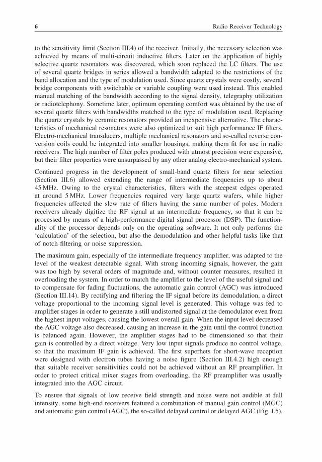
To ensure that signals of low receive field strength and noise were not audible at fullintensity, some high-end receivers featured a combination of manual gain control (MGC)and automatic gain control (AGC), the so-called delayed control or delayed AGC (Fig. I.5).

Functional Principle of Radio Receivers 7
Correctlydimensioned AGC
Delayed AGC
MGC
VRX
VAF
Figure I.5 Functional principle of different RX control methods. In the case of manual control thepreset gain is kept constant, that is, the AF output voltage follows the RF input voltage proportion-ally. The characteristic curve can be shifted in parallel by changing the MGC voltage (the requiredcontrol voltage is supplied from an adjustable constant voltage source). If dimensioned correctly,the automatic gain control (AGC) maintains a constant AF output voltage over a wide range ofinput voltages. The delayed AGC is not effective with weak input signals, but becomes active whenthe signal exceeds a certain preadjusted threshold and automatically maintains a constant AF outputvoltage – it is therefore called the ‘delayed’ gain control.
The automatic control of the gain cuts in only at a certain level, while with lower RFinput signals the gain was kept constant. This means that up to an adjustable thresholdboth the input signal and the output signal increased proportionally. Thus, the audibilityof both weak input signals and noise is attenuated to the same degree [2]. This makesthe receiver sound clearer. In addition, the sometimes annoying response of the AGC tointerfering signals of frequencies close to the receiving frequency (Section III.8.2) thatmay occur with weak useful signals, can be limited.
During the time when radio signals were transmitted in the form of audible telegraphy oramplitude-modulation signals a simple diode detector was entirely suitable as a demod-ulator. This was followed by a variable multi-stage AF amplifier for sound reproductionin headphones or loudspeakers. In order to make simple telegraphy signals audible anoscillator signal was fed to the last IF stage in such a way that a beat was generatedin the demodulator as a result of this signal and the received signal. When the receivedsignal frequency was in the centre of the IF passband (see Figure III.42) and the frequencyof the beat-frequency oscillator deviated by, for example, 1 kHz, a keyed carrier becameaudible as a pulsating 1 kHz tone. This beat frequency oscillator (BFO) is therefore knownas heterodyne oscillator (LO).
With strong input signals the generation of the beat no longer produces satisfactory results.The loose coupling was therefore soon replaced by a separate mixing stage, called theproduct detector since its output signal is generated by multiplicative mixing. With productdetectors it then became possible to demodulate single-side-band (SSB) modulation thatcould not be processed with an AM detector.

8 Radio Receiver Technology
Besides the task of developing a large-signal mixer, a symmetrical quartz filter with steepedges or a satisfactorily functioning AGC (that is well adapted to the modulation typeused), especially the design of a variable local oscillator for the superhet presented anenormous challenge for the receiver developer.
The first heterodyning oscillators oscillated freely. Tuning was either capacitive by arotatable capacitor or inductive after ferrites became available. The first generation ofprofessional equipment used an oscillator resonance circuit that varied synchronouslywith the input circuits of the RF amplifier stages. For this the variable capacitors hadthe same number of plate packages as the number of circuits that needed tuning. In mostamateur radio equipment, however, the input circuits were tuned separately from theoscillator for practical reasons. Any major detuning of the oscillator therefore requiredreadjusting of the preselector. The frequency of the freely oscillating oscillators was lowerthan the received frequency. The higher the tuning frequency the lower was the stabilitywith varying supply voltages and temperatures. Frequency stability could be achievedonly by utmost mechanical precision in oscillator construction, the integration of coldthermostats, and the use of components having defined temperature coefficients. By com-bining these measures an optimum compensation was obtained over a wide temperaturerange. Manufacturing a frequency-stabilized tuning oscillator was difficult, even withindustrial production methods, and required extra efforts of testing and measuring.
In order to prevent frequency fluctuations due to changing supply voltages and/or loads,oscillators are usually supplied with voltages from electronically regulated sources. Loadvariations originating from the mixing stage or subsequent amplifier or keying stagesduring data transmission are counteracted by incorporating at least one additional bufferstage. Its only task is the electrical isolation of the oscillator from the following circuits.
In the beginning, the receive frequency was indicated as an analog value by means ofa dial mounted on the axis of the oscillator tuning element. The dial markings directlyindicated the receive frequencies or wavelengths and, in the case of broadcast receivers,showed the stations that could be received. (A few units had a mechanical digital displayof the frequency. Among them were the NCX-5 transceiver from National and the 51S-1professional receiver from Collins. They allowed a tuning accuracy of 1 kHz.)
An accurate reproduction of the tuned-in frequency was possible only with a digital fre-quency counter used for determining and displaying the operating frequency. The displayelements used were Nixie tubes, later the LED dot-matrix or seven-element displays, andrecently mostly LC displays. To indicate the receive frequency, the frequency counted atthe oscillator must be corrected when resetting the counter either by direct comparison ofthe BFO frequency counted in a similar manner or by preprogramming the complements.
I.2.2 Multiple-Conversion Superhet
The mixer stage of a superheterodyne receiver satisfies the mathematical condition forgenerating an intermediate frequency from the heterodyne signal with two different receivefrequencies (III.5.3). Both the difference between the receive frequency (fRX) and theLO frequency (fLO) and the difference between the LO frequency and a second receivefrequency generate the same intermediate frequency (fIF). The two receive frequencies

Functional Principle of Radio Receivers 9
form a mirror image relative to the frequency of the oscillator, both separated by the IF.The unwanted receive frequency is therefore called the image frequency. The frequencyof any such signal is equal to the IF and directly affects the wanted signal or, in extremecases, covers it altogether. To avoid this, the image frequency must be suppressed. This isusually done by preselection, i.e. by means of the resonance circuits of the RF preamplifieror the preselector. At the beginning of the superhet era the near selection (Section III.6),responsible for the selectivity by filtering the useful signal from the adjacent signals,was possible only with high-quality multi-circuit bandpass filters having a low frequency.From the actual image frequency it is obvious that, for a low IF, it can be suppressed onlywith a considerable amount of filtering. Especially with receivers designed for severalfrequency ranges, the reception of high-frequency signals was strongly affected by aninsufficiently suppressed image frequency (Section III.5.3). It was therefore necessary tofind a compromise between image frequency suppression and selectivity, based on theintermediate frequency.
This problem was solved by twofold heterodyning. To reject the image frequency thefirst IF was made as high as possible; the higher the IF the lower the effort to suppressthe image frequency (see Fig. III.36). A second mixer converted to a second IF so lowthat good near selection was possible at an acceptable cost (Fig. I.6). But the secondmixer again produces both a useful frequency and an image frequency. The second imagefrequency must also be suppressed as far as possible by means of a filter operating onthe first IF. In the era of coil filters this required very careful selection of the frequency.
Selection
VRX
fRX fRX fIF1
fLO1 fLO2
fIF1 fIF1 fIF2
fIF2 fIF2 fAF VAF
RFamplifier
IF filter
IF filter Demodulator AFamplifier
IFamplifier
1st local oscillator 2nd local oscillator
2nd IF stage
1st IF stage
1st mixer 2nd mixer
IFamplifier
Figure I.6 Operating principle of multiple-conversion superheterodyne receivers. The designshown here is called a dual-conversion superhet. The first IF is a high frequency and serves mainlyto prevent receiving image frequencies. The second mixer changes to a lower IF in order to performthe main selection.

10 Radio Receiver Technology
The higher the first IF was chosen in the dual-conversion superhet, the more difficult itbecame to manufacture a variable freely-oscillating first local oscillator with a frequencylow enough to cause sufficient frequency drifts (Section III.15), for example, for stabletelegraphy reception at narrow bandwidths. If the LO frequency was above the receivefrequency in one frequency range and below it in the other, the analog frequency scaleshad to be marked in opposing directions, making operating the equipment cumbersome.Attempts were therefore made to stabilize the first oscillator as well as possible. Initially,this utilized the converter method – the first oscillator remained untuned and was stabi-lized by a quartz element, while tuning was achieved with the second local oscillator.However, this required that the filter of the first IF be as wide as the entire tuning range.This design was used in almost all early equipment generations for semi-professional use(including amateur radio service) like those produced by Heathkit or Collins. In order tominimize overloading due to the high number of receiving stations within one band, thetuning range was limited to only a few hundred kHz. In the Collins unit, featuring electrontubes, the first IF was merely 200 kHz wide. With a tunable second local oscillator at alower frequency the conversion to a lower, narrower second IF was simple and stable.
Nevertheless, the problem of large-signal immunity (Section III.12) remained. By usinga first tunable local oscillator at a high frequency it was attempted to again reduce thebandwidth of the first IF to the strictly necessary maximum bandwidth, depending on thewidest modulation type to be demodulated. At first, the premix system was used. Thisconsisted of a low-frequency tuned oscillator of sufficient frequency stability and a mixerfor converting the signal to the required frequency by means of switchable signals fromthe quartz oscillators. Since the mixing process produced spurious emissions, subsequentfiltering with switchable bandwidths was necessary. This is a complex method, but freeof the deficiencies described above. It established itself with Drake and TenTec in thesemi-professional sector (Fig. I.7). With a tunable first local oscillator it is sufficient forthe second LO to use a simple quartz oscillator with a fixed frequency.
As long as the required frequency bands were restricted to a reasonable number (like theshort-wave broadcasting bands or the classical five bands of amateur radio services) thisprinciple left nothing to be desired. However, the need for receivers covering all frequencyranges from <1 MHz to 30 MHz inevitably increased the number of expensive quartzelements and increased the demands on near selection of the premixer. This changed onlywith the availability of low-cost digital integrated semiconductor circuits, which simplifiedfrequency dividing. When dividing the output frequency of an oscillator to a low frequencyand comparing it with the divided frequency of a reference signal stabilized by quartzelements, the oscillator can be synchronized by means of a voltage-dependent component(like a varactor diode) using a direct voltage derived from the phase difference between thetwo signals for retuning the oscillator. This was the beginning of phase-locked loops (PLL)and voltage-controlled oscillators (VCO) (Fig. I.8). Particularly the PLL circuits gavean enormous boost to the advancement of frequency tuning in receivers. Today, highlyintegrated circuits enable the design of complex and powerful tuned oscillator systemsfor all frequency ranges. Using several control loops they achieve very high resolutionwith very small frequency tuning increments [3], short settling times (Section III.15) evenwith wide frequency variations, and little sideband noise (Section III.7.1). Those circuitsused for generating heterodyne signals are called synthesizers.

Functional Principle of Radio Receivers 11
Band selection
f0 fvar
fLO
VLO
Band-settingoscillator
Low-frequencytuning oscillator
Mixer
Figure I.7 Architecture of a premixer assembly which feeds an LO injection signal of a stablefrequency to the first mixer of a multiple-conversion superhet receiver. The separately depictedcircuit design of switchable quartz elements is of course part of an oscillator in actual equipment.
But it is necessary to use processors to make such circuits more ergonomic and themany functions easier to use. With processors the operating frequency can be tunedalmost continuously by means of an optical encoder or be activated directly by a numberentered via the keyboard. It is possible to store many frequencies in a memory. In thelatest developments the loop for fine-tuning is replaced by direct digital synthesis (DDS)(Fig. I.9). This generates an artificial sinusoidal from the digital input information andthe signal is tunable in increments of �1 Hz. It is controlled by the operating processor,
Voltage-controlledoscillator
fLO
fLO/n fref/N fref
Vdiff
VdiffG ⋅Vdiff
Direct-voltageamplifier
Low-passfilter
n N
1 1j
Divider DividerReferenceoscillator
Phasedetector
Figure I.8 VCO with phase-locked loop. The direct voltage Vdiff for automatic frequency trackingis smoothed in the so-called loop filter to prevent spurious signals and sideband noise. Vdiff is adaptedto the required voltage range of the voltage-controlled oscillator via subsequent amplification bythe factor G. This results in the constant output frequency fLO = n · fref /N.

12 Radio Receiver Technology
Figure I.9 Complete DDS capable of producing output signals up to 400 MHz with a resolutionof 14 bits. Only a reference clock and a low-pass filter must be provided externally. (Companyphotograph of Analog Devices.)
which is required in any case. Depending on the resolution of the D/A converter inthe DDS module the output signal generated has very little phase noise (Fig. III.50)and unwanted spurious components (Fig. III.51). Owing to the rapid progress made inthis technology DDS generators are currently used in almost every radio receiver. Fullyintegrated circuits that can generate output signals up to 500 MHz are available. (Anexample of this technology is AD9912 from Analog Devices, featuring a phase noise aslow as −131 dBc/Hz at 10 kHz separation distance with an output frequency of 150 MHz.The output frequency can be varied by increments as small as 3.6 μHz [4]. The spuriousemissions actually occurring depend to a large extent on the type of programming.)
It was quickly realized that large-signal problems can be eliminated only if the first narrow-band selection takes place in an early stage of the receive path. In multiple-conversionsystems quartz filters with a frequency in the range of about 5 MHz to 130 MHz weretherefore included already in the first IF. The first IF is amplified just enough so thatthe subsequent stages do not noticeably affect the overall noise factor (Section V.1). Inhigh-linearity RF frontends there is no amplification at all upstream of the first mixer.The narrower the bandwidth in the first IF the higher is its relieving effect for the secondmixer. Usually the second mixer stage is much simpler than the first mixer. Nowadays, thelatest high-end radio receivers match the selected bandwidth already in the first IF stage tothe respective transmission method by switching roofing filters (Fig. I.10). (Quartz filtersare used in most cases. The commonly used term ‘roofing’ filter indicates its protectiveeffect on all subsequent stages, just as the roof of a house protects all rooms underneathfrom the weather.) This satisfies the need for matching the selection to the modulation inorder to achieve optimum large-signal immunity or for processing the useful signal withlow frequency spacing to strong interferences.
For the second IF, almost all professional receivers used a frequency for which selectionfilters were readily available on the market, usually the frequency of 455 kHz. Telefunkendeveloped their own mechanical filters of 200 kHz and 500 kHz, while Japanese developerschose to use their own frequencies, probably for competitive reasons. In professionalsystems amplification was made so high that the AGC cut in even with the weakestsignals. This made such signals strong enough to be displayed (Section III.14) and to