radio frequency identification (rfid) based plate
TRANSCRIPT

RADIO FREQUENCY IDENTIFICATION (RFID) BASED PLATE
RECOGNITION FOR REGISTERED VEHICLE IN UMP
NUR ALIAA BINTI MOHD EZANEE
A thesis submitted in fulfilment of the requirements
for the award of the
Bachelor ofComputer Science (Computer Systems & Networking)
Faculty of Computer Systems and Software Engineering
Universiti Malaysia Pahang
JUNE, 2012
RADIO-FREQUENCY IDENTIFICATION (RFID) BASED PLATE RECOGNITION FOR REGISTERED VEHICLE IN UMP
ABSTRACT
Recent advances technology in world of computer resolve the difficulty of
recognition. Based on technology of Radio-Frequency (RFID) has enhanced a project of
plate recognition for registered vehicle specially proposed to Universiti Malaysia Pahang.
The scopes of work is study and develop a passive tag RFID system in detection of RFID
Reader from input to output composed of hardware, database development and software
programming VisualBasic.Net. Method and implementation conducted by stages due to
the system requirements needed. RFID Plate Recognition solves the problems of
unauthorized vehicle entering campus of UMP without inspection and come out with a
number of statistics vehicle check-in and check-out day-by-day.
Keywords: Knowledge Radio-Frequency Identification

RADIO-FREQUENCY IDENTIFICATION (RFID) BASED PLATE RECOGNITION FOR REGISTERED VEHICLE IN UMP
ABSTRAK
Kemajuan teknologi terkini dalam dunia komputer menyelesaikan kesukaran
pengiktirafan. Berdasarkan teknologi Frekuensi Radio (RFID) telah menghasilkan projek
pengiktirafan nombor plat kenderaan yang berdaftar sebagai kenderaan sah di Univesiti
Malaysia Pahang. Skp kerja merupakan kajian dan pembangunan sistem RFID beserta
sistem tag pasif dalam pengesanan RFID Reader untuk input daripada perkakasan,
pembangunan pangkalan data dan perisian perngaturcaraan VisualBasic.net.
Kaedah dan perlaksanaan yang dijalankan secara berperingkat mengikut proses-
proses tertentu. Sistem ini menyelesaikan masalah kenderaan kampus yang dibenarkan
memasuki kawasan Universiti Malaysia Pahang (UMP) tanpa pemeriksaan dan
merangkumi statistik daftar kenderaan keluar dan masuk setiap hari.
Kata kunci: Pengetahuan Pengenalan Frekuensi Radio
RADIO-FREQUENCY IDENTIFICATION (RFID) BASED PLATE RECOGNITION FOR REGISTERED VEHICLE IN UMP
TABLE OF CONTENT
CHAPTER TITLE PAGE
1 INTRODUCTION 1
1.1 Introduction 1
1.2 Problem Statement 3
1.3 Objective 3
1.4 Scope 4
1.5 Thesis Organization 4
2 LITERATURE REVIEW 5
2.1 Radio-Frequency Identification (RFID) 5
2.1.1 The Arrival of RFID 6
2.2 RFID Tag 8
2.2.1 Passive Tag 9
2.2.2 Semi-active (Semi-passive) Tag 10
2.2.3 Active Tag 11
2.3 RFID Reader 12
2.4 RFID Antenna 14
2.5 Radio Wave 16
2.6 Advantages and Disadvantages of RFID
& Comparison with Barcode 18
2.7 Existing Related System of RIFD 20
2.7.1 Auto-checkout System for Retails
using Radio Frequency Identification
(RFID) Technology 20
2.7.2 Automatic Number Plate Recognition
for Australian Conditions 22
2.7.3 A RFID Configuration with an
Enhanced Recognition Property for
Indoor Positioning 24

RADIO-FREQUENCY IDENTIFICATION (RFID) BASED PLATE RECOGNITION FOR REGISTERED VEHICLE IN UMP
3 RESEARCH METHODOLOGY 26
3.1 Introduction of Method 27
3.2 RIFD Architecture 28
3.2.1 Input Process 29
3.2.2 Detection 29
3.2.3 System 30
3.2.4 Result 30
3.2.5 Mechanism of Design 30
3.3 Software and Hardware Tools 31
3.3.1 Hardware 31
3.3.2 Software 32
3.4 Construction 34
3.5 Context Diagram 37
3.6 Data Flow Diagram Level 0 38
3.7 Data Flow Diagram Level 1 39
3.8 Process of Database Design 30
4 IMPLEMENTATION 41
4.1 Result 41
4.2 System Interface 42
4.3 Database Constructions and Tables 45
4.4 Interface Design 47
5 RESULT AND DISSCUSSION 52
5.1 Result Analysis 53
5.2 Constraints 54
5.3 Future Research 55
6 CONCLUSION 56
6.1 Result Analysis 57
6.2 Lesson Learn 58
RADIO-FREQUENCY IDENTIFICATION (RFID) BASED PLATE RECOGNITION FOR REGISTERED VEHICLE IN UMP
REFRENCES 59
APPENDIX 60
LIST OF FIGURES
TABLE TITLE PAGE
Figure 2.1a Radio Frequency Identification (RFID) 6
Figure 2.1b Process of RFID 7
Figure 2.1c RFID mostly applied for toll system 7
Figure 2.2a RFID Tag 8
Figure 2.2b Semi-active Tag 10
Figure 2.2c Semi-passive Tag 10
Figure 2.2d Active Tag 11
Figure 2.3a RFID Reader 12
Figure 2.4a RFID Antenna 15
Figure 2.5a Radio Frequency Transmission & Reflection 16
Figure 2.5b Radio Frequency Reader & Tag Antenna 17
Figure 2.5c Radio Frequency Energy 17
Figure 2.6a Barcode System 18
Figure 2.7a Flowchart for Auto-checkout System for Retails 21
Figure 2.7b Automatic Number Plate Recognition 23
Figure 2.7c Figure of Enhanced Recognition Property 25
Figure 3.1a Use case Diagram 27
Figure 3.2a Flow Chart Design of The System 28
Figure 3.2b The Mechanism of Design 30
Figure 3.4a Flow Chart for User and Security Guard 34
Figure 3.4b Interface System for Registered Vehicle in UMP 35
Figure 3.4c Interface System for Unregistered Vehicle in UMP 36
Figure 3.4d Interface Statistics of Registered Vehicle Check-in
& Check-out with time
36
Figure 3.5a Context Diagram 37
Figure 3.6a DFD Level 0 38
Figure 3.7a DFD Level 1 39
RADIO-FREQUENCY IDENTIFICATION (RFID) BASED PLATE RECOGNITION FOR REGISTERED VEHICLE IN UMP
Figure 4.2a Consistency and Standard Interface 42
Figure 4.2b Error Prevention Interface 43
Figure 4.2c Recover Interface 44
Figure 4.3a ADMIN_INFO Database 45
Figure 4.3b STAFF_INFO Database 45
Figure 4.3c STUDENT_INFO Database 46
Figure 4.3d VEHICLE_INFO Database 46
Figure 4.5a Welcome Log in Page 47
Figure 4.5b Sign Up 47
Figure 4.5c Home Page 48
Figure 4.5d Staff Application 48
Figure 4.5e Student Application 49
Figure 4.5f Staff Information 49
Figure 4.5g Student Information 50
Figure 4.5h Check In Vehicle 50
Figure 4.5i Vehicle Information 51
LIST OF TABLES
TABLE TITLE PAGE
Table 2.2a Passive Tag 9
Table 2.3a RFID Reader Components 13
Table 2.4a RFID Antenna Characteristics 15
Table 2.6a Comparison of RFID & Barcode 19
Table 3.3a Hardware Requirements 32
Table 3.3b Software Requirements 33
Table 3.8a Admin Database Design 39
Table 3.8b Staff/student Database Design 40
RADIO-FREQUENCY IDENTIFICATION (RFID) BASED PLATE RECOGNITION FOR REGISTERED VEHICLE IN UMP
CHAPTER 1
1.0 INTRODUCTION
Radio-Frequency Identification (RFID) Based Plate Recognition for
Registered Vehicle in UMP is one of project by the concept of RFID technology
which is an automatic identification method, relying on storing and remotely
retrieving data using its devices such as tags and responders.
1.1 Introduction
RFID for plate recognition is a system for process of check in and out of
the main gate of Universiti Malaysia Pahang (UMP). It is design for only
registered vehicle in UMP to make sure UMP staffs & students to get more secure
and safety guarantees.
RADIO-FREQUENCY IDENTIFICATION (RFID) BASED PLATE RECOGNITION FOR REGISTERED VEHICLE IN UMP
RFID basically is a Radio-Frequency Identification that use radio waves to
transfer data from electronic tag, through some reader and attached to an object to
be identified or to be tracked. It transmits the identity of an object wirelessly
grouped under broad category of automatic identification technologies [1]. RFID
contains three (3) main parts, firstly is the tag, second is the reader and last part is
the antenna. An RFID tag has three (3) types such as passive, active and battery
assisted passive. In this system, by using a passive RFID, a tag without battery
can be read in long range to the RFID reader. It is because by using the radio
wave, the reader is not necessary read the tag (plate number) in straight line and it
also can be read hundreds at a time [1]. Most RFID contain at least two (2) parts,
one is an integrated circuit for storing and processing information, modulating and
demodulating a radio-frequency (RF) signal and the other part is the antenna for
receiving and transmitting the signal [2]. The data transmitted by tag may provide
identification or specified information. Other advantage of RFID is it‟s effective
in any environment where tags can be sealed within plastics enclosure eliminating
due to expose of chemicals, heat, abrasion, dirt and grease build-up, etc [3].
The system will allow identify registered vehicle in and out of the campus
of UMP by recognition of the vehicle plate number. When the reader of RFID
can recognize the tag of vehicle plate number, it directly show the vehicle owner
details as it is been transmitted in the system and the vehicle barrier quickly open.
Then, the registered vehicle of UMP staffs & students can check in and also check
out from campus of UMP easily.
RADIO-FREQUENCY IDENTIFICATION (RFID) BASED PLATE RECOGNITION FOR REGISTERED VEHICLE IN UMP
1.2 Problem Statement
The problem statements that have lead to this project are:
1) Unauthorized vehicle entering campus of UMP without inspection.
2) Time consuming when frequently check in for each vehicle that passes by
the barrier.
3) Numbers of vehicle check in and out of UMP campus are unknown.
The first problem is about unauthorized vehicle entering campus without
inspection causes security issue. The problem occur when sometimes vehicle just
pass through the entrance of security without stopping by so no authorization
process could be done.
Secondly is time consuming when vehicle have to stop for screening process
at the entrance when security need to check for identification card of student and
staff and also for unauthorized vehicle need to report manually so it consume time
for other vehicle queue up at the line of entrance.
University campus always has many visitors so do the community itself. So as
the third problem is numbers of vehicle check in and out of the campus are
unknown. It is a problem as we cannot really estimate how many vehicle checks
in and are the vehicle check out the same day or not for unauthorized vehicle. And
also for authorized vehicle, they need to be in campus before 12p.m so the
security will record any vehicle coming in late night.
So the objective of the system can help to develop solutions to solve the
problem statement.
1.3 Objective
The objectives of this project are:
1) To develop a prototype of RFID systems for vehicle plate recognition.
2) To recognize the vehicle that only registered in UMP will be allowed to
enter the campus of UMP.
3) To make statistics on the number of vehicles check in and out of the
campus UMP.
RADIO-FREQUENCY IDENTIFICATION (RFID) BASED PLATE RECOGNITION FOR REGISTERED VEHICLE IN UMP
1.4 Scope
There will be three (3) scopes that will discussed in details which is:
1) Administration
- The system managed by administrator.
2) Security Guards
- The system handled by security guards.
3) User
- The user of the system is the staffs & students UMP who registered
their vehicle in the system.
1.5 Thesis Organization
This thesis consists of six (6) chapters which I described chapter by chapter:
i. CHAPTER 1: Introduction
This chapter briefly contains the whole idea by introduction, problem
statement, objective, scopes and thesis organization.
ii. CHAPTER 2: Literature Review
The purpose of this chapter is about the review for the chosen project,
divided into two (2) sub-reviews that require a study to get complete
information about the project.
iii. CHAPTER 3: Methodology
The content will included all the method, technique or any approach that
will be used while designing and implementing the project.
iv. CHAPTER 4: Implementation
The purpose of this chapter is to explain about all the processes involve
in the development project.
v. CHAPTER 5: Result and Discussion
This chapter will explain the result and data analysis that had been
acquired.
vi. CHAPTER 6: Conclusion
This chapter explains about overall description about the project and its
summarization.
RADIO-FREQUENCY IDENTIFICATION (RFID) BASED PLATE RECOGNITION FOR REGISTERED VEHICLE IN UMP
CHAPTER 2
2.0 LITERATURE REVIEW
This chapter will review on the existing research based on article, journal
or any kind of resources that can give guides on addition of knowledge and
information to produce a good system based to the topic proposed before.
This will include on technically what is the system are about and the kind
of methodology of the existing systems during the research.
2.1 Radio-Frequency Identification (RFID)
Radio-Frequency Identification that is also known as RFID in general term
of Information & Communications Technology (ICT) world. RFID is all widely
about a technology that uses radio waves to transfer data from an electronic tag or
label to an object, through a reader for purpose of identifying and tracking the
object [1]. According to Nemai Chandra Karmakar (2010) states that RFID is a
wireless data capturing technique from a tagged item. The RFID tags or
RADIO-FREQUENCY IDENTIFICATION (RFID) BASED PLATE RECOGNITION FOR REGISTERED VEHICLE IN UMP
transponders are high-frequency electronic circuits that allow the items to be
remotely detected, identified and to be tracked by the position of the items itself
[11]. From Patrick J. Sweeney II (2005), he claims that RFID is a very valuable in
business and technology tools holds the promise of replacing existing
identification technologies like the bar code.
2.1.1 The Arrival of RFID
Based on array technology innovation in 1940s, RFID roots in early
military systems. A reflected radio signal identifies a remote object based on the
reflection signature from the object from paper of journal “Communication by
Means if Reflected Power” 1948.
In early of 196Os, the RFID explode with the theory related to RFID
“Theory of Loaded Scatterers” in 1964. RFID related inventions such as
“Remotely activated radio frequency powered devices” by Robert Richardson‟s
and “Passive data transmission techniques utilizing radar echoes” by J. H.
Vogelman until the first century opens with the smallest microwave tags built
using at a minimum two components; a single custom CMOS integrated circuit
and an antenna. Tag was creating as sticky labels, easy attached to windshields
and for objects to be managed well. The use of electronic for collection toll had
become popular systems to applied with RFID system especially in United States
and had develop to other country as well.
Figure 2.1a – Radio Frequency Identification (RFID)
RADIO-FREQUENCY IDENTIFICATION (RFID) BASED PLATE RECOGNITION FOR REGISTERED VEHICLE IN UMP
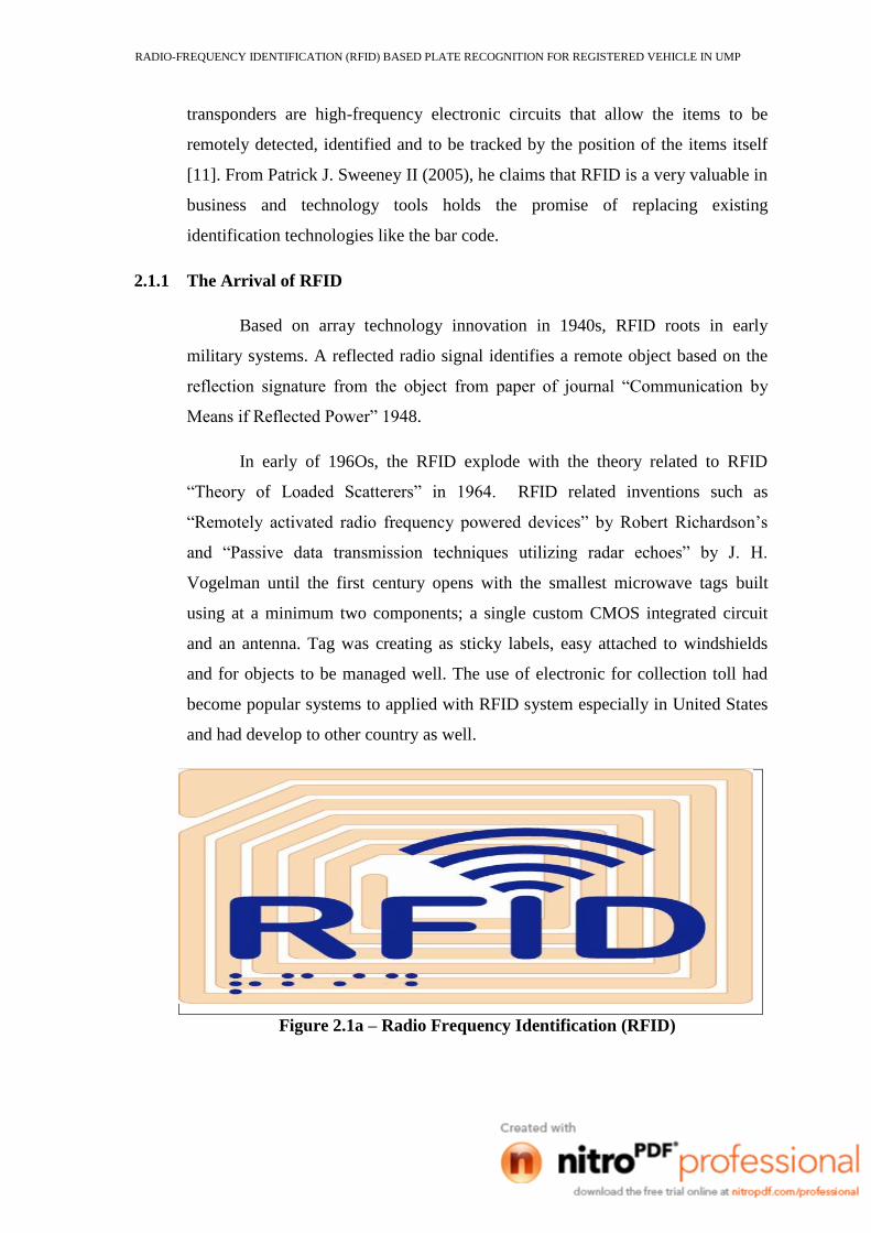
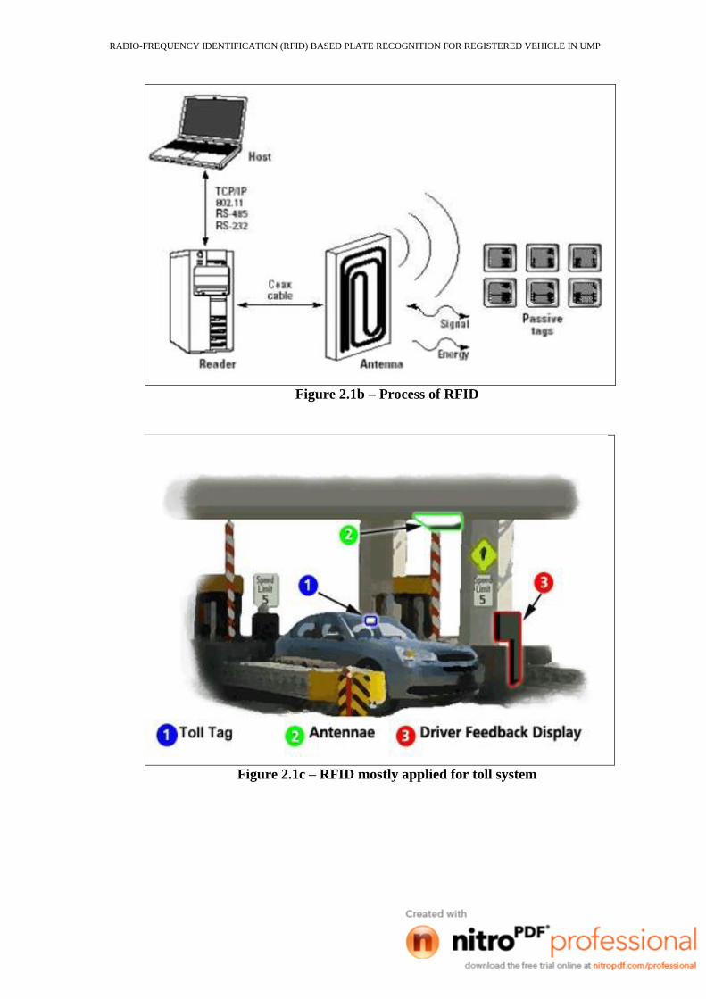
Figure 2.1b – Process of RFID
Figure 2.1c – RFID mostly applied for toll system
RADIO-FREQUENCY IDENTIFICATION (RFID) BASED PLATE RECOGNITION FOR REGISTERED VEHICLE IN UMP
2.2 RFID Tag
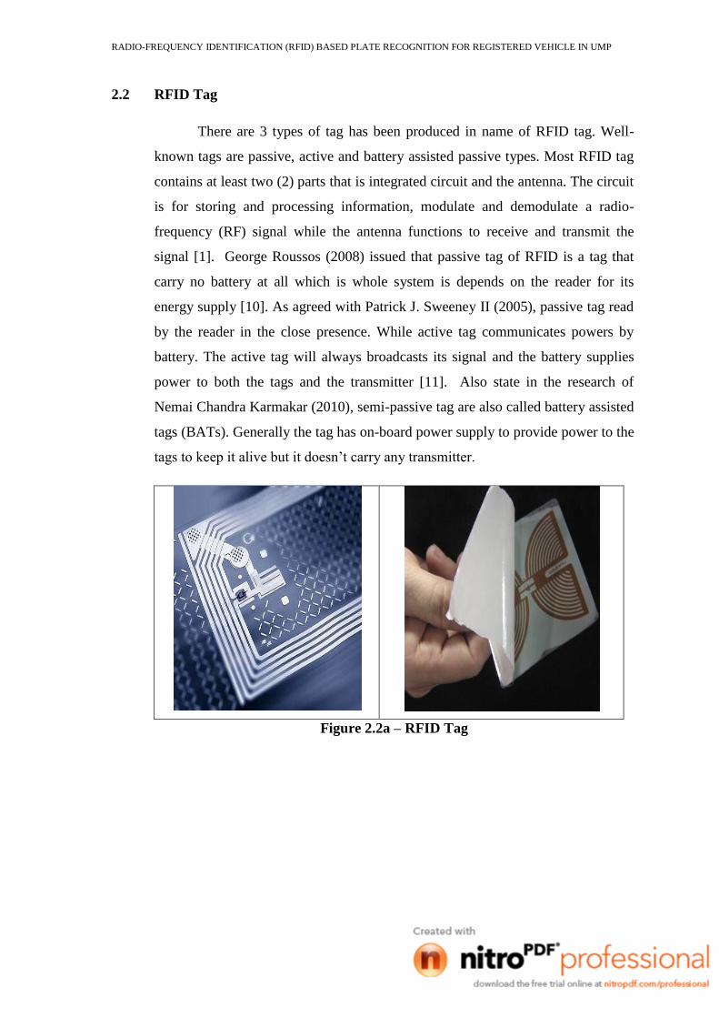
There are 3 types of tag has been produced in name of RFID tag. Well-
known tags are passive, active and battery assisted passive types. Most RFID tag
contains at least two (2) parts that is integrated circuit and the antenna. The circuit
is for storing and processing information, modulate and demodulate a radio-
frequency (RF) signal while the antenna functions to receive and transmit the
signal [1]. George Roussos (2008) issued that passive tag of RFID is a tag that
carry no battery at all which is whole system is depends on the reader for its
energy supply [10]. As agreed with Patrick J. Sweeney II (2005), passive tag read
by the reader in the close presence. While active tag communicates powers by
battery. The active tag will always broadcasts its signal and the battery supplies
power to both the tags and the transmitter [11]. Also state in the research of
Nemai Chandra Karmakar (2010), semi-passive tag are also called battery assisted
tags (BATs). Generally the tag has on-board power supply to provide power to the
tags to keep it alive but it doesn‟t carry any transmitter.
Figure 2.2a – RFID Tag
RADIO-FREQUENCY IDENTIFICATION (RFID) BASED PLATE RECOGNITION FOR REGISTERED VEHICLE IN UMP
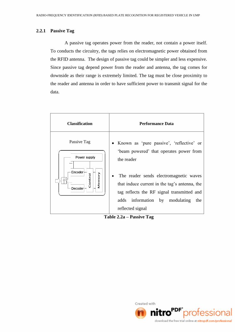
2.2.1 Passive Tag
A passive tag operates power from the reader, not contain a power itself.
To conducts the circuitry, the tags relies on electromagnetic power obtained from
the RFID antenna. The design of passive tag could be simpler and less expensive.
Since passive tag depend power from the reader and antenna, the tag comes for
downside as their range is extremely limited. The tag must be close proximity to
the reader and antenna in order to have sufficient power to transmit signal for the
data.
Classification
Performance Data
Passive Tag
Known as „pure passive‟, „reflective‟ or
„beam powered‟ that operates power from
the reader
The reader sends electromagnetic waves
that induce current in the tag‟s antenna, the
tag reflects the RF signal transmitted and
adds information by modulating the
reflected signal
Table 2.2a – Passive Tag
RADIO-FREQUENCY IDENTIFICATION (RFID) BASED PLATE RECOGNITION FOR REGISTERED VEHICLE IN UMP
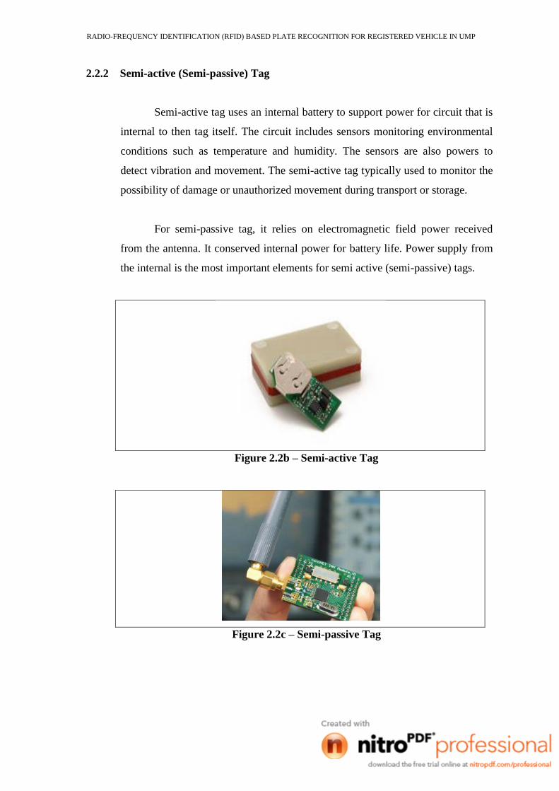
2.2.2 Semi-active (Semi-passive) Tag
Semi-active tag uses an internal battery to support power for circuit that is
internal to then tag itself. The circuit includes sensors monitoring environmental
conditions such as temperature and humidity. The sensors are also powers to
detect vibration and movement. The semi-active tag typically used to monitor the
possibility of damage or unauthorized movement during transport or storage.
For semi-passive tag, it relies on electromagnetic field power received
from the antenna. It conserved internal power for battery life. Power supply from
the internal is the most important elements for semi active (semi-passive) tags.
Figure 2.2b – Semi-active Tag
Figure 2.2c – Semi-passive Tag
RADIO-FREQUENCY IDENTIFICATION (RFID) BASED PLATE RECOGNITION FOR REGISTERED VEHICLE IN UMP
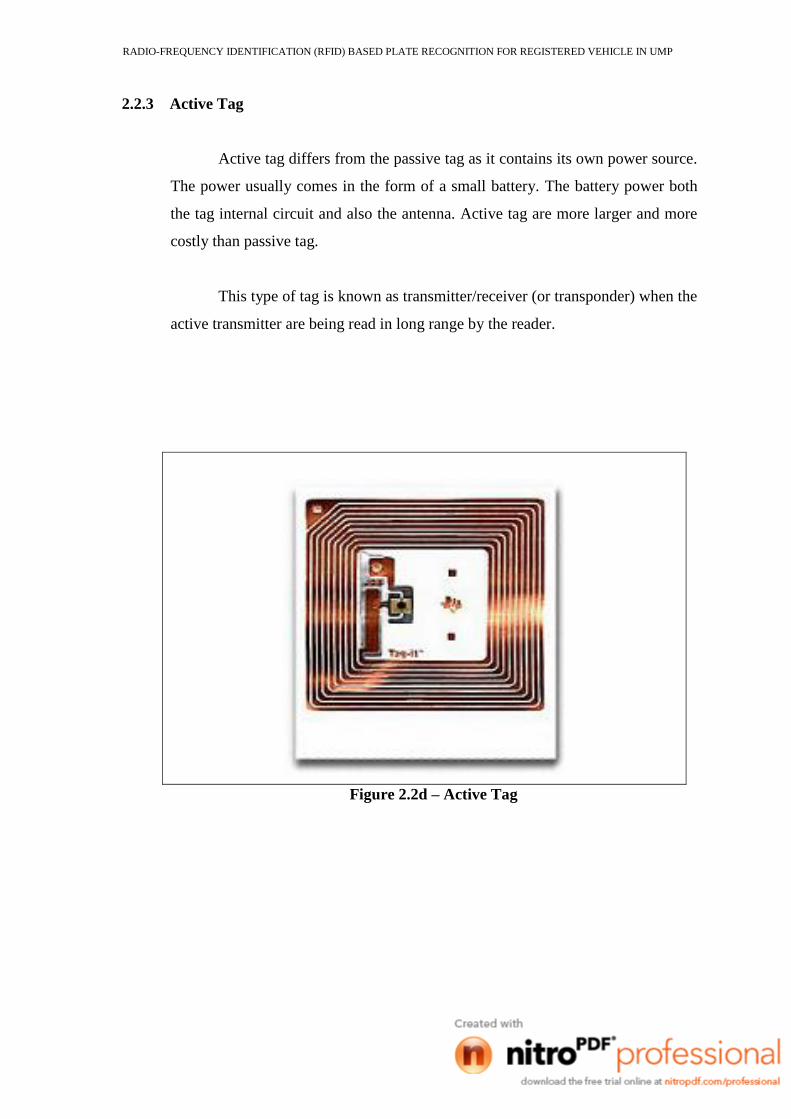
2.2.3 Active Tag
Active tag differs from the passive tag as it contains its own power source.
The power usually comes in the form of a small battery. The battery power both
the tag internal circuit and also the antenna. Active tag are more larger and more
costly than passive tag.
This type of tag is known as transmitter/receiver (or transponder) when the
active transmitter are being read in long range by the reader.
Figure 2.2d – Active Tag
RADIO-FREQUENCY IDENTIFICATION (RFID) BASED PLATE RECOGNITION FOR REGISTERED VEHICLE IN UMP
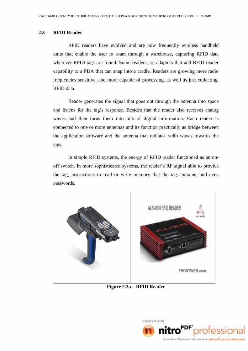
2.3 RFID Reader
RFID readers have evolved and are now frequently wireless handheld
units that enable the user to roam through a warehouse, capturing RFID data
wherever RFID tags are found. Some readers are adapters that add RFID reader
capability to a PDA that can snap into a cradle. Readers are growing more radio
frequencies sensitive, and more capable of processing, as well as just collecting,
RFID data.
Reader generates the signal that goes out through the antenna into space
and listens for the tag‟s response. Besides that the reader also receives analog
waves and then turns them into bits of digital information. Each reader is
connected to one or more antennas and its function practically as bridge between
the application software and the antenna that radiates radio waves towards the
tags.
In simple RFID systems, the energy of RFID reader functioned as an on-
off switch. In more sophisticated systems, the reader‟s RF signal able to provide
the tag, instructions to read or write memory that the tag contains, and even
passwords.
Figure 2.3a – RFID Reader
RADIO-FREQUENCY IDENTIFICATION (RFID) BASED PLATE RECOGNITION FOR REGISTERED VEHICLE IN UMP
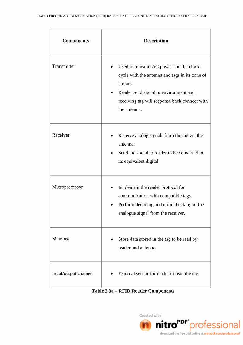
Components
Description
Transmitter
Used to transmit AC power and the clock
cycle with the antenna and tags in its zone of
circuit.
Reader send signal to environment and
receiving tag will response back connect with
the antenna.
Receiver
Receive analog signals from the tag via the
antenna.
Send the signal to reader to be converted to
its equivalent digital.
Microprocessor
Implement the reader protocol for
communication with compatible tags.
Perform decoding and error checking of the
analogue signal from the receiver.
Memory
Store data stored in the tag to be read by
reader and antenna.
Input/output channel
External sensor for reader to read the tag.
Table 2.3a – RFID Reader Components
RADIO-FREQUENCY IDENTIFICATION (RFID) BASED PLATE RECOGNITION FOR REGISTERED VEHICLE IN UMP
2.4 RFID Antenna
The RFID physical layer consist antennas used to couple the reader to the tag
so that information can be transferred between the frequencies at which it
oscillates and the strength or power of those oscillations.
Most RFID systems use unlicensed spectrum, which is a specific part of
the spectrum set aside for use without a radio license. Popular bands are the low-
frequency (LF) band at 125 - 134.2 KHz, the high-frequency (HF) band at
13.56MHz, the ultrahigh-frequency (UHF) band a 915MHz and the industrial,
scientific, and medical (ISM) band at 2.4GHz.[2]
The energy that is radiated from an antenna is dividing into two parts:
a. the near field-part of radiation that is within a small number of
wavelengths of the antenna
b. the far field- the energy that is radiated beyond the near field
The low-frequency (LF) and high-frequency (HF) RFID systems are operate
in the near field while ultrahigh-frequency (UHF) and industrial, scientific, and
medical (ISM) RFID systems operate in the far field.
The larger the antenna on the reader and the tag, the better an RFID
system will work because large antennas are generally more efficient at
transmitting and receiving radio power than are small antennas. Thus, a large
antenna on the reader means that more power can be sent to the RFID tag and
more of the tag‟s emitted energy can be collected and analysed. A large antenna
on the tag means that more of the power can be collected and used to power the
chip. Likewise, a large antenna on the chip means that more power can be
transmitted back to the reader.
RADIO-FREQUENCY IDENTIFICATION (RFID) BASED PLATE RECOGNITION FOR REGISTERED VEHICLE IN UMP
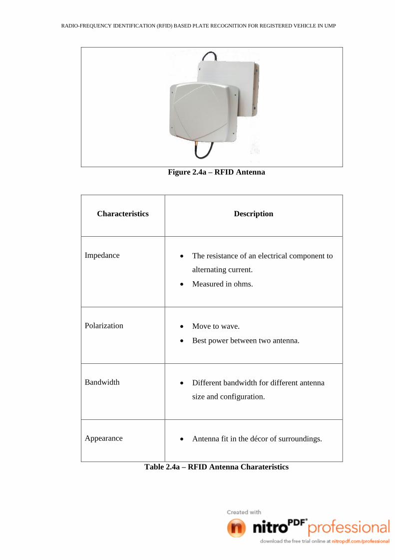
Figure 2.4a – RFID Antenna
Characteristics
Description
Impedance
The resistance of an electrical component to
alternating current.
Measured in ohms.
Polarization
Move to wave.
Best power between two antenna.
Bandwidth
Different bandwidth for different antenna
size and configuration.
Appearance
Antenna fit in the décor of surroundings.
Table 2.4a – RFID Antenna Charateristics
RADIO-FREQUENCY IDENTIFICATION (RFID) BASED PLATE RECOGNITION FOR REGISTERED VEHICLE IN UMP
2.5 Radio Wave
From the author of Basic Concepts in RFID Technology by Richard
Moscatiello states that the radio waves that function are a kind of electromagnetic
waves so do with the light and x-rays. The number of waves that occur in one
second is known as the frequency and it is measured in Hertz. One Hertz is equal
to one wave oscillation per second.
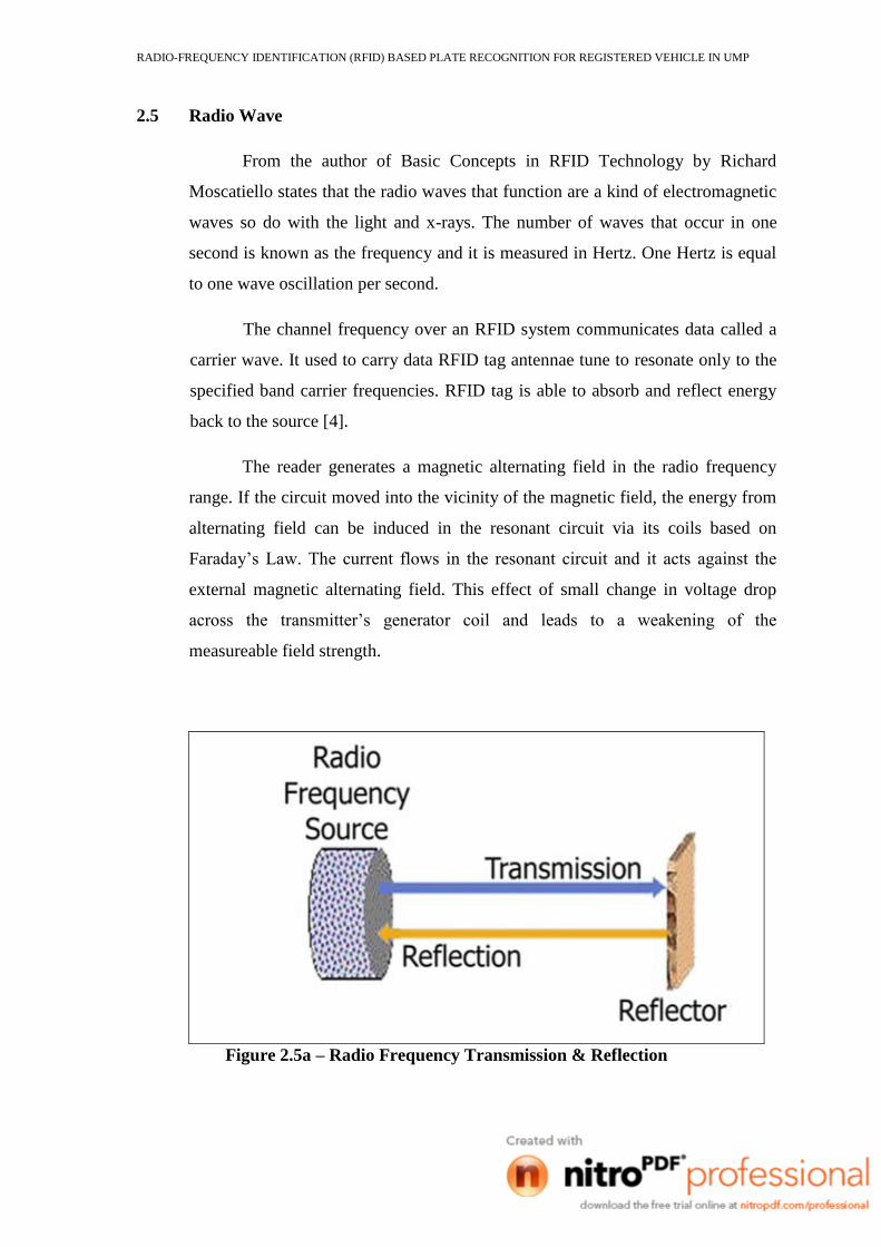
The channel frequency over an RFID system communicates data called a
carrier wave. It used to carry data RFID tag antennae tune to resonate only to the
specified band carrier frequencies. RFID tag is able to absorb and reflect energy
back to the source [4].
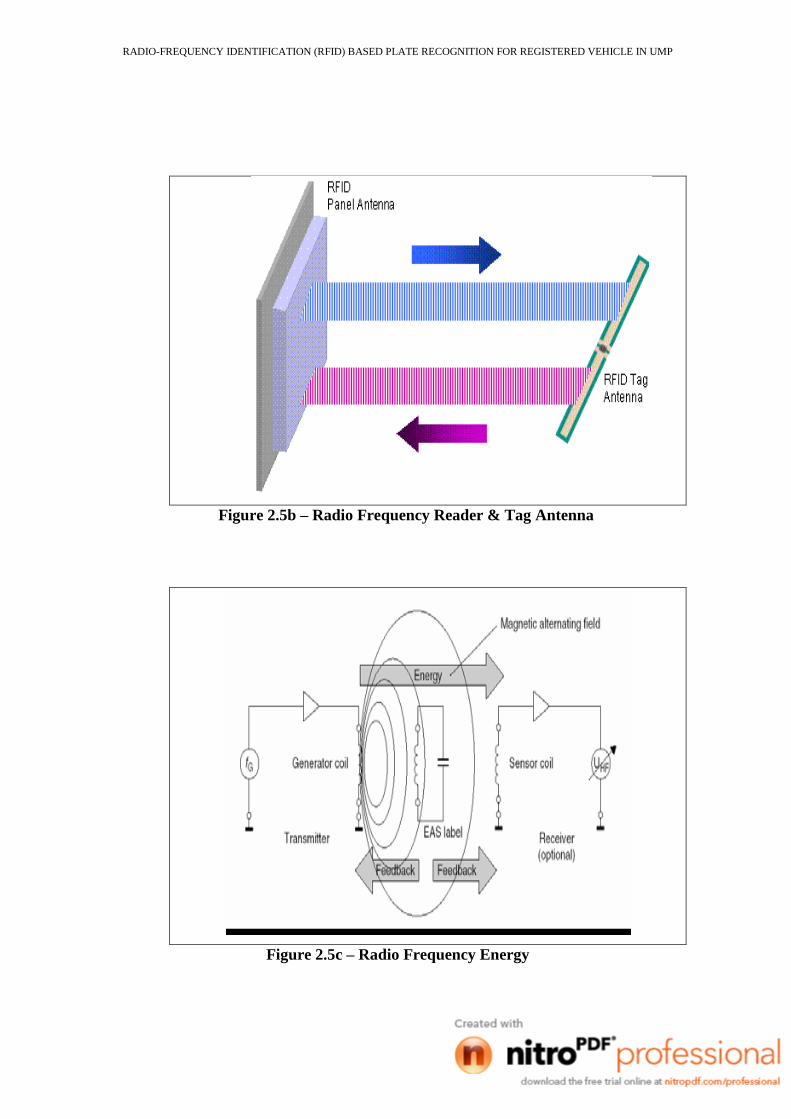
The reader generates a magnetic alternating field in the radio frequency
range. If the circuit moved into the vicinity of the magnetic field, the energy from
alternating field can be induced in the resonant circuit via its coils based on
Faraday‟s Law. The current flows in the resonant circuit and it acts against the
external magnetic alternating field. This effect of small change in voltage drop
across the transmitter‟s generator coil and leads to a weakening of the
measureable field strength.
Figure 2.5a – Radio Frequency Transmission & Reflection
RADIO-FREQUENCY IDENTIFICATION (RFID) BASED PLATE RECOGNITION FOR REGISTERED VEHICLE IN UMP
Figure 2.5b – Radio Frequency Reader & Tag Antenna
Figure 2.5c – Radio Frequency Energy