radio frequency backscatter communication for high data
TRANSCRIPT
Abstract— In this paper, we study radio frequency (RF)
backscatter for high data rate wireless communication with deep
medical implants. The radar approach permits remote reading of
the implant’s information. This means the active transmitter is
removed from the implant, that results in significant power saving.
We customize our design for wireless capsule endoscopy (WCE)
application, which is used for streaming high data rate video
signals for improved visualization of the gastrointestinal tract. An
efficient antenna system is designed and integrated into the WCE
prototype that generates large radar cross section (RCS) using a
self-resonant antenna geometry. The antenna is reconfigurable
using an active micro-watt switch, which is controlled by the data
stream. The switch alters the antenna RCS for an efficient
modulation of the incident electromagnetic wave (EM)
transmitted from outside the body. The antenna design considers
the specific conditions of wave propagation in the biological
environments and antenna loading with the lossy tissues.
Polarization diversity using bi-static on-body reader antennas is
used for communicating with the implant device. The on-body
antennas can direct EM energy to the capsule device for improving
the backscatter link performance. The feasibility study is
demonstrated using numerical computations and experimentally
validated in a liquid phantom and in-vivo animal experiments. A
reliable backscatter data connectivity of 1 and 5 Mbps is measured
for the capsule in the gastrointestinal tract for the depths up to 10
cm using an acceptable level of RF radiations.
Index Terms—Antenna system, backscatter communication,
implant antenna, biomedical applications, Wireless capsule
endoscopy (WCE), Wireless communications.
I. INTRODUCTION
CTIVE wireless communication requires transceivers and
the power resources for operation. Backscatter data
telemetry is an approach that can eliminate the active
transmitter from a device and save power, space, and cost. By
using radio frequency (RF) backscatter, a remote reader can
power up the data source of a tag device and the tag modulates
the RF reflections back into the propagation channel for data
communications. In this technique, the tag device remains
The paper submitted on July 2018. The work has been supported by the EU’s
H2020: ITN:MSCA:WIBEC project (grant no. 675353) and the Research
Council of Norway projects “High data-rate wireless communication for deep medical implants” (grant no. 282110) and “Wireless In-body Sensor and
Actuator Networks” (grant no. 270957). The antenna is a part of the patent
“Medical Implant with Wireless Communication”, application no. 62201-15239-GB-1, 2016.
Ali Khaleghi is with Intervention Center, Oslo University Hospital, Oslo
Norway, and Norwegian University of Science and Technology (NTNU), Trondheim, Norway, [email protected].
passive and does not require the RF frontend for
communications. Semi-passive tag device uses battery
resources for activating the data source, and the communication
is based on the backscatter technique. In the semi-passive tag,
the communication range can be increased, and the tag can have
more power resources for sensing and processing.
The well-known implementation of RF backscatter is radio
frequency identification (RFID) [1]- [2] that communicates a
specific code for the identification purposes. The
communication can be realized using near-field coupling in low
frequency (LF) or high frequency (HF) by implementing the
coupling coils in which the range is several centimeters and the
data rate is several Kbps; alternatively, the radiative fields in
ultra-high frequencies (UHF) can be used for range extension
to several meters and data rates of several tens of Kbps.
Integration of sensors with RFID tag activates the technology
for wireless sensor networks (WSN) for dynamic sensory data
transmission [3]. The target applications are for the scenarios in
which the active transmitter technology cannot be integrated
into the tag device due to efficiency/power consumption
balance while considering weight/size constraints. Using high
data rate backscatter has significant potential for the future low
power wireless connectivity. A short range, high data rate
wireless backscatter communication in free space has been
presented in [4]. We have demonstrated a long range (10-15 m)
backscatter communication for image data transmission [5],
and a battery-free video streaming using RF backscatter and
power harvesting was presented in [6].
An important application of the RF backscatter is for the
biomedical implant sensors in which the physical access to the
implant is restricted, and the battery resources are limited due
to the nature of the implant device. The wireless backscatter
technology might enable internet connectivity to the bio-
implant sensors [7]. This means it can have a significant impact
on the future implant technology.
The backscatter communication with an implant is different
from a device operating in free space. This is due to the different
A. Hasanvand is with the electrical engineering department of K.N. Toosi
University of Technology, Tehran, Iran. I. Balasingham is with Intervention
Center, Oslo University Hospital, Oslo, Norway and the Norwegian University of Science and Technology (NTNU), Trondheim, Norway,
Radio Frequency Backscatter Communication
for High Data Rate Deep Implants
Ali Khaleghi, Senior Member, IEEE, Aminolah Hasanvand, Ilangko Balasingham Senior Member,
IEEE
A

wave propagation nature in the biological tissues, radiated
power limitations and the implant size restrictions in which the
communication range and data rates are significantly reduced.
RFID technology for the medical implant connectivity has been
studied previously in which a limited communication range and
data rates were reported [8]- [12]. Using magnetic induction at
LF and HF can provide wireless power transfer (WPT) and data
telemetry for superficial implants located in a few centimeters
of depths [13]- [14]. The magnetic field indicates less loss in
the biological tissues, but it is further limited to the reader coil
proximity and is highly sensitive to the relative orientation of
the reader and implant coils. Thus this limits the read range of
the device [10]; in addition, the data rate is limited by the
narrowband nature of the magnetic induction system. Using
propagation modes in UHF frequencies, one can increase the
read range of the device. Moreover, larger bandwidth can be
used for high data rate connectivity because more efficient
antennas with less sensitivity to the orientation can be realized.
However, the communication range is limited by the wave
propagation loss in the biological environment. This leads to a
shorter reader range achieved considering the RF safety
requirement imposed by the specific absorption rate (SAR)
[15]- [16].
Using backscatter for high data rates sensory systems such as
neurological implants and wireless capsule endoscopy (WCE)
is a feature for future medical technologies. The requirement
for these devices is continuous or real-time data transmission,
within depth inside the body, which is not feasible by using the
active transmission approaches. In this paper, for the first time,
we address using backscatter communication for high data rate
deep implants, such as for WCE with continuous data/video
streaming. The proposed RF backscatter uses a semi-passive
approach in which the sensory system or camera powers by an
onboard battery and the wireless communication is based on the
backscatter technique. The RF frontend in the capsule device is
replaced with a micro/nano watt electronic switch. This means
the power consumption of a typical active transmitter, which is
in the order of 20-45 mW can be eliminated. Thus continuous
high data rate, real-time video streaming without reducing the
lifetime of the device can be enabled. Our approach is mainly
focused on the antenna system design for the implant and the
reader system in which we use the near-field characteristics of
the reader antenna in UHF band to increase the communication
range. To accomplish the antenna design, the knowledge of EM
wave propagation in the biological tissues, small antenna design
for efficient RF reflections, and interaction of antennas with the
biological environment are used to improve the communication
system efficiency for providing connectivity in depths greater
than 10 cm. In our design, the capsule length is 20 mm (the
integrated antenna length is about 10 mm), and the diameter is
less than 10 mm to fit into a swallowable shell. The frequencies
used for the data communications must be in the regulated
medical bands and should have a low loss in propagation
through the human organs. Also, the RF radiation safety must
be considered in the design process.
The paper is organized as follows. In Section II, we discuss the
limitation of small antennas and their usage in the biological
mediums. In Section III, the key design considerations for
implant backscatter antenna is discussed. In Section IV, the
antenna design and analysis with integration for backscatter
WCE system are presented, followed by the on-body reader
antenna design and configuration in Section V. The link
simulations and the reader antenna requirements are analyzed
in Section VI. The backscatter antenna simulation,
measurements in a liquid phantom and in-vivo animal
experiments are provided in Section VII. Section VIII is the
discussion and conclusions.
II. SMALL ANTENNAS IN BIOLOGICAL TISSUES
The biological tissues contain significant water and minerals
that impose high permittivity and conductivity into the medium.
These material properties are frequency dependent and have
been measured primarily by Gabriel [17]. The tissues with high
water contents indicate high permittivity values. Depending on
the minerals, the tissues can have different conductivities. The
conductivity increases for higher frequencies and is the source
of electromagnetic wave attenuation through transmission in
the biological medium. Fig. 1 shows the permittivity and
conductivity of selected tissues (muscle, fat, intestine, bones
and blood) in the frequency range of 100 to 3000 MHz. The
conductivity is smaller for low frequencies, so is preferred for
signal transmission inside the biological tissues due to the
amount of the loss. The permittivity is high for the tissues with
higher water contents.
Fig. 1 Conductivity and permittivity versus frequency for the sample biological
tissues of muscle, fat, intestine, bones and blood.
In a communication system, the antenna is a part of the
transmission path and plays a crucial role on EM wave coupling
to/from the medium. Thus the combined effects of the antenna
and the material loss constitute EM wave coupling between
transceiver devices in the biological environment.
The main limitation with the antennas is the size constraint
and the antenna usage inside the lossy biological tissues. The
implant device should be small enough to be implanted
permanently or temporally for medical sensing and actuation.
Also, the antenna should hold a specific planar or conformal
geometry depending on the application scenarios such as WCE,
0 500 1000 1500 2000 2500 30000
1
2
3
4
Frequency (MHz)
(S
/m)
Muscle
Fat
Intestine
Bones
Blood
0 500 1000 1500 2000 2500 30000
20
40
60
80
100
Frequency (MHz)
Pe
rmitiv
itty
(
r )
Muscle
Fat
Intestine
Bones
Blood
leadless pacemaker or wireless neuronal implants.
The frequency regulatory body also has a definition for the
frequencies which can be used for the medical sensing. FCC
and ITU define these frequencies while some countries have
their standards [18]-[20]. The medical frequencies are placed in
the bands at 400, 600, 800, and 1400 MHz due to their
availability, loss characteristics in the biological medium and
the applications from the medical sectors [21]. Considering the
implant’s physical size, maximum 35 mm, and the
recommended frequencies, the normalized implant size is
usually less than 0.05 λ ~ 0.16λ (λ is the wavelength in free
space) for the above mentioned upper and lower frequencies.
Reminding that a part of the device size is assigned for the
antenna integration, the available space for the implant antenna
is much less than the size mentioned above. WCE is used in the
small intestine and has a cylindrical shape with the available
antenna length of 10 to 15 mm and a diameter of about 9 mm.
Small antennas in free space have been thoroughly
investigated [22]. The main character of these antennas is the
significant amount of the reactive field nearby the antenna
structure. This causes a high amount of coupling from the
antenna to the surrounding environment. Thus, the presence of
any lossy material, cable or electronics in the close perimeter of
the antenna alters the current distribution on the antenna
structure and makes the antenna impedance and radiation
character more susceptible to the surrounding medium.
Furthermore, the small antenna radiation resistance is very
small making it difficult to tune the transmitter/ receiver device
without significant loss in the matching network. Even, by
using a suitable matching, the current flow on the antenna
structure can be high. Thus more considerable ohmic losses
reduce the radiation efficiency.
Using small antennas immersed in the biological medium is
further limited, due to the strong near-field of the small
antennas and the close perimeter to the lossy medium;
therefore, significant loss by the near-field loading is inevitable.
The loss effect can be observed in the antenna input resistance
(Rin) as the ohmic resistance (RΩ) added to the antenna radiation
resistance (Rr), i.e., Rin= RΩ+Rr. As Rr is very small for small
antennas and RΩ is significant due to the material loss, therefore
the embedded antenna input resistance (Rin) is managed by the
loss. The ohmic resistance might be reduced by holding a gap
between the metallic antenna structure and the surrounding
medium to detach the antenna near-field from the lossy
environment. However, the added space reduces the space for
the antenna. We have investigated the gap around the antenna
for the conceptual antennas, loop and dipole, and we found that
a minimum air space of 0.5 mm around the antenna is required
to keep the antenna radiation efficiency as maximum as
possible. The larger gaps have less effect on the antenna
efficiency and reduce the antenna’s physical space. Overall, it
is required to increase the radiation resistance of a small implant
antenna for efficient operation with less influence from the
surrounding lossy medium. This consideration is carried out in
our antenna design.
We note that designing a high efficient antenna may not be a
critical requirement for the systems with active transmitters,
considering the design complexity and the size requirements.
The reason is that increasing the transmitter power in some
extends can compensate for the low antenna efficiency. The
assumption is that the significant part of the DC power is used
to run the local oscillators and modulator of an RF frontend
rather than the RF power amplification, i.e., increasing the RF
power level by some dB will slightly increase the percentage of
the system DC power consumption.
For the backscatter usage, the antenna efficiency plays a
crucial role in the communication link performance. It is
challenging to compensate the poor antenna efficiency by
transmitting a considerable amount of power from the external
reader, which has to abide by the spectral emission limitations
and RF safety issues.
III. BACKSCATTER ANTENNA FOR IMPLANTS
In a backscatter communication system, the wave
propagation is conducted in round way from the reader to the
tag device. The operation principle is that the amplitude/phase
of the incident wave is altered by the tag antenna switching in a
way that the antenna reflections are modulated. The data source
controls the wave reflections; thus the reader can extract the
tag’s information. In the backscatter link, the antenna radar
cross section (RCS) is considered as the primary way of
carrying communication signals in which the antenna gain and
efficiency are applied for both reception and re-radiation
modes.
RCS calculations for plane wave illumination and aperture
antenna assumptions for the tag has been provided [23]- [24].
Also, the RCS depends on the load connected to the tag antenna
and the structural mode (As) which has a load-independent
antenna factor [24]. The Thevenin equivalent circuit model is
proposed for the minimum scattering antennas (MSA) which
provides RCS as [23],
𝜎 =𝜆2𝐺2𝑅𝑎
2
𝜋|𝑍𝑎+𝑍𝑙𝑜𝑎𝑑|2 (1)
where λ is the wavelength, G is the antenna gain in the same
direction of the incident EM wave, Za= Ra+jXa is the complex
radiation impedance of the antenna and Zload is the antenna’s
load impedance. For backscatter communication, the
modulation vector is essential to discriminate among the data
signals [24]-[25]. It is specified by the differential RCS (ΔRCS)
vector of the antenna. The ΔRCS can be managed by altering
the antenna reflections using different antenna loads [25]- [27].
In a passive RFID tag, the RF signal is used in a rectifier
diode circuit, and the energy is stored in a capacitor for the
system operation. For an RFID integrated circuit (IC), Zload is
the IC input impedance. For maximum power transfer, the
antenna impedance must be conjugately matched to the IC
impedance. With the conjugate matching, ideally, half of the
power is delivered to the load and half is reflected into the
antenna. For backscatter data communications, maximum
reflections (1) are required, that can be attained with Zload=0, in
which RCS value depends on the antenna complex impedance
(Za= Ra+jXa) [23]. Based on (1), the maximum reflection is

obtained in the resonance frequency of a self-resonant antenna
(Xa=0) using the short circuit load impedance (Zload=0), or by
using a pure imaginary conjugate matched load (Zload=-jXa).
Using the passive tags with a matched load for wireless
power transfer and a short circuit for maximum reflections, the
ΔRCS is reduced due to the power reflections from the matched
load. For a semi-passive tag device, the power transfer is not
the system operation task, and the device’s data source is
activated using an onboard battery. Therefore, the antenna
impedance match is not required, and open circuit (Zload=∞) is
used to minimize the antenna reflections, or a load impedance
can be optimized to provide maximum reflection with a tuned
phase for maximum ΔRCS vector [24]. The procedure for
finding the optimized antenna load impedances for a semi-
passive tag in free space is provided in [24].
Using the backscatter for the implant communication is
different from the free space. The reader signal must penetrate
inside the human subject, the permittivity of the human body is
high compared to the air interface. Thus significant impedance
mismatch occurs by wave propagation from the free-space to
in-body [28]. Using the reader antennas in proximity to the
body surface can reduce the mismatch effect for better EM
wave coupling into the body. In this usage, the communication
is limited to the view angles of the on-body reader antennas.
Using bi-static reader, the reader antennas should be held close
to the tag antenna in the common coverage area for successful
communications. High coupling between antennas would
prevent a successful data reading because of the transmitter
signal leakage into the receiver that limits the dynamic range of
the receiver and can cause the receiver saturation. This will
require using polarization and space diversity to interrogate
with the implant device to minimize the coupling. Moreover,
the implant device is in several centimeters depth and operates
in the medical frequencies thus the tag device remains in the
reader’s near-field region. Therefore, the aperture antenna
assumption used for the RCS calculation in (1), the same far
field antenna gain in the forward and backward paths and the
plane wave assumption are not entirely valid for the implant
backscatter antennas.
The small antennas have little radiation resistance and are
highly reactive. The lossy medium dissipates the reactive field
as heat in the proximity of the antenna which appears as an
ohmic loss in the antenna input impedance. The amount of the
ohmic loss is significant compared to the low radiation
resistance (Rr) of the small antenna. Thus the equivalent
Thevenin model (1) shall consider the ohmic loss for the
implant backscatter case. Furthermore, the implant antenna
impedance is sensitive to the antenna loading with the
surrounding biological medium in which a fixed value of
loading for WPT or backscatter cannot be considered for
providing maximum RCS.
Due to the issues mentioned above and different usage
conditions compared to the free space, the backscatter
communication formulas might be revised for the implant
usage. In this paper, we mainly focus on the engineering
solutions and designs using computational electromagnetics
approach rather than the analytical analyses.
IV. IMPLANT ANTENNA DESIGN
Radiation efficiency of an antenna depends on the antenna’s
physical size and dimensions compared to the wavelength [22].
The swallowable WCE has a maximum length of 25 mm and a
diameter less than 10 mm; it travels through the human gastric
tract and transmits the captured pictures/video to an external
body device for the visualization of the small or large intestine
for diagnosis. The available space for our antenna is 10-12 mm
in length and 9 mm in diameter, where the rest of the space is
allocated to the camera, light source, electronic boards and the
batteries. The antenna is encapsulated in a biocompatible shell.
The WCE device can be accessed from the belly within the
depth of 10 cm from the front body, and deeper depths (if
required) may be accessed from the back side of the body.
Due to the round way path loss through the biological tissues,
the effect of the antenna gain and efficiency in both the
reception and re-radiation modes and to establish a reliable
communication link with reader antennas, a precise antenna
design for backscatter must be considered. This requires a self-
resonant antenna to maximize the wave reflections, and a semi-
passive backscatter approach to increase the discrimination
between the wave reflections, ΔRCS.
The maximum available space is used to achieve the
maximum antenna efficiency. A planar conformal antenna that
can be integrated into the perimeter of a cylindrical capsule
device is designed. Therefore, the antenna interior space can be
used for the integration of the other electronics to save the
space. The target frequency band of operation is placed at 608-
614 MHz which is allocated for the Wireless Medical
Telemetry Service (WMTS). By considering the wavelength,
the maximum antenna length is 0.02 λ at 600 MHz band. For
the given antenna size, operating at the lower medical
frequency bands around 450 MHz reduces the antenna’s
normalized size (0.015λ), and thus the antenna efficiency is
further reduced. Using frequencies above 800 MHz, even
increase the antenna normalized size (0.026λ), indicates more
EM wave loss by transmission through the biological medium
due to the increased conductivity of the tissues. Thus more
loss/cm results. In conclusion, the operating frequency must be
compromised in relation to the antenna size in which there will
be a range of frequencies that can provide maximum radiation
efficiency of a biologically embedded antenna.
The general form of the antennas are dipole and loop
configurations in which the dipole antenna has an open current
path, and a loop antenna constitutes a closed current path. The
loop antenna has an intense magnetic near-field which
dissipates much less power to the surrounding tissues than the
dipole antennas with a strong electric field. Thus a small loop
antenna results in better efficiency in the biological tissues [29].
The reason for improved efficiency with the loop antennas is
the magnetic permeability of the biological tissues that is
lossless (µr=1). However, the electric permittivity is lossy
(complex εr). The main problem with using small loop antennas
is the substantial current flow on the antenna surface due to the
small radiation resistance. This means the antenna ohmic loss
reduces the efficiency. Here, we start the design with a
meander-shaped loop antenna geometry to reduce the near field

loss in the biological tissues. Then the antenna feeding is
modified to generate a self-resonant geometry with a tunable
input resistance for an improved antenna efficiency in the
biological tissues.
The designed meander loop antenna has several bend lines
and is connected to the feed ground to constitute a closed
current path (Fig. 2(a)). The planar antenna is used in a
cylindrical conformal geometry to be integrated into a WCE
device (Fig. 2(b)). The vertical meander lines are 11.5 mm, the
horizontal lines are 2 mm, and the path width is 0.5 mm. The
antenna material is in Copper with the conductivity of
σ=5.8×10⁷ S/m and thickness of 35 microns. The antenna is
integrated inside a capsule shell of permittivity (εr=4.3,
σ=0.0054) with a gap of 0.5 mm to the shell and the shell
thickness of 0.5 mm. The simulation model includes a metallic
cylinder underneath the meander antenna to simulate the battery
and the other electronics effects (Fig. 2(c)). The initial
simulation, modeling, and parametric analysis were conducted
in the homogenous biological tissue of single layer muscle as
the basis for our calculations. Frequency-dependent material
property of the muscle is considered in the simulations. The
final design and implementation use the heterogeneous
anatomical model of the human body and animal experiments.
Fig. 2(d) shows the simulation model inside a muscle sphere of
radius 10 cm. The numerical electromagnetic computations are
conducted using CST Microwave Studio (MWS) using Time
domain and the Frequency domain solvers to compare the
accuracy of the computations for the small structure. Close
agreement between the simulations can be achieved by using
high-density mesh in the time domain solver using the local
mesh options. The frequency domain solver is more accurate
for the small size structures but cannot be used in the
simulations with the human body anatomical model using the
Voxel data.
The simulated antenna impedances (real and imaginary) in the
muscle tissue is shown in Figs. 3 (a), (b). The imaginary part of
the impedance can be separated into two regions. Frequencies
below 700 MHz, in which the antenna reactance is inductive,
and above 700 MHz, in which the reactance is capacitive. The
antenna input resistance can be expressed as, Rin=Rr+Rc+Rm,
where Rr is the radiation resistance, Rc+Rm is the ohmic loss
resistance (Rc is the conductor loss, and Rm is due to the
biological material loss). In the transition region at 700 MHz,
the antenna behaves as an open circuit with high input
resistance, and the antenna input resistance reduces above and
below the transition region, in which the conductor loss and
material loss are negligible compared to the high radiation
resistance, i.e., the antenna input resistance is mainly managed
by the radiation resistance. For the frequencies far from the
transition region, the antenna resistance is dominated by the
loss resistance, i.e. Rr < Rc+Rm. By using the meander loop
geometry, we can realize an antenna with a wide range of input
resistances from several ohms to several kilo ohms in different
frequencies. The antenna requires a matching circuit in any
frequency in the range for optimal operation with resonance.
To minimize the effect of the antenna medium (ohmic loss
resistance) in the antenna input resistance, for an efficient
Fig. 2 Meander loop antenna geometry a) planar b) conformal cylindrical
geometry c) integrated antenna inside a glass shell d) simulation scenario,
muscle embedded antenna
Fig. 3 Meander loop antenna input impedance a) imaginary b) real
radiation, we can operate in a frequency in which the radiation
resistance is much larger than the loss resistance, so more
significant part of the source power can be delivered to the
antenna for radiations and less current paths through the circuit
for reduced ohmic loss. We note that the antenna input
resistance cannot be substantial (kilo-ohm range) that might
prevent the current flow along the antenna structure that is
applied by the source signal. Therefore, it is essential to select
an appropriate frequency of operation with a moderate input
resistance (30-200 ohms).

Fig. 4 Meander loop antenna geometry with parasitic patch feed a) planar b) conformal cylindrical geometry. Patch length= 11.5 mm, patch width=2 mm,
meander trace width= 0.5 mm, line spacing 1 mm.
Fig. 5 Input impedance for the capacitive feed meander loop antenna inside muscle sphere a) imaginary b) real; the antenna resonances at 600 MHz with
Rin=36 ohms.
It is required to provide a resonance frequency in the
frequency region in which the radiation resistance is larger than
the loss resistance to realize an efficient antenna for the
backscatter. Also the incident wave/ source signal must
generate the current flow along the antenna structure. For this
purpose, a capacitive section is added to the meander antenna
as shown in Fig. 4 using a patch monopole antenna. The patch
is very small compared to the wavelength, and provides high
capacitive reactance. By coupling the patch capacitance via a
gap to the meander section, and by measuring the antenna input
impedance from the patch feed point, the antenna self-
resonance occurs by shifting down the inductive reactance of
the loop in Fig. 3(a), as shown in Fig. 5(a). Fig. 5 shows the real
and imaginary parts of the capacitive feed antenna in the muscle
sphere using a coupling gap of 0.2 mm (see Fig. 4(a)). The gap
to the meander section manages the coupling coefficient. The
patch length manages the capacitance value. The overall effect
is that the capacitive reactance of the patch removes the
inductive reactance of the loop, and this generates a resonance
frequency. The amount of the capacitive reactance defines the
resonance frequency in which the antenna input resistance can
be defined. Therefore, depending on the capacitive reactance,
the resonance can be tuned in any frequency from 500 to 700
MHz with different antenna resistance. As the antenna
normalized size and material loss changes slightly in the
frequency range, the variation on the input resistance of the
antenna is mainly related to the radiation resistance. The
optimum operating frequency for the backscatter is the
resonance frequency in which the antenna input resistance is
much larger than the ohmic resistance for maximum backscatter
with reduced effect of the surrounded tissues.
For the backscatter communication in the biological tissues,
the patch is connected to an RF switch which is controlled by a
serial data source. The switch connects/ disconnects the patch
to the RF ground strip. By providing the closed path in the
circuit, the antenna resonance is generated, and the maximum
power from the incident field to the antenna is delivered. Short
circuit state is used to re-radiate the maximum absorbed power
into the biological medium. The open switch disconnects the
resonance circuit, and with no resonance state, the minimum
reflections from the antenna circuit are provided. The antenna
operating frequency is tuned at 604 MHz with an input
resistance of 40 Ω, of which the ohmic resistance is calculated
10 Ω.
Using Thevenin equivalent circuit approximation (1), we can
define the antenna input impedance as 𝑍𝑖𝑛 = 𝑅𝑟 + 𝑅𝛺 + 𝑗𝑋𝑖𝑛
and 𝑍𝑙𝑜𝑎𝑑 is {0 or ∞} for the short/open states of the switch,
respectively. We observe that in the resonance frequency, Xin =0, with, 𝑍𝑙𝑜𝑎𝑑 ≈ 0, the maximum reflection occurs by
minimizing 𝑅Ω relative to 𝑅r of the antenna. Therefore, it is
essential to tune the antenna operating frequency within region
𝑅r ≫ 𝑅Ω. However, larger 𝑅r limits the current flow in the
antenna structure for an applied incident electric field. Also as
ΔRCS is used as the basis for data modulation, using large
𝑅r performs similar to the open circuit switch state with low
current and thus no modulation would occur with switching. A
compromise between efficient reflection for large RCS and
high ΔRCS must be considered to achieve optimal operation for
the backscatter. The patch length and gap to the meander
section are used for adjusting the optimum backscatter
frequency in the predefined design frequency.
V. ON-BODY READER ANTENNA
The bi-static radar approach is used to read the capsule
endoscopy data. The reader antennas are attached to the body
surface to couple EM wave into the body toward the implant
antenna. As the distance from the reader antenna to the implant
is several centimeters and the antenna coverage angle is limited,
the implant antenna must be found in the view angle of the
reader antenna. Therefore, it is required to use an array of reader
antennas on the body surface and switch among the array
elements for an efficient coverage over all the digestive tract.
Also, the bi-static reader antennas must be placed in the
proximity to each other to transmit and receive the backscatter
signals in the antenna coverage region. Using small distance
between the antennas causes significant coupling that reduces
the dynamic range of the receiver and might cause the receiver

saturation. This may lead to signal distortion in the receiver.
Polarization diversity is used to control the coupling level
between the reader antennas.
Different antennas are designed and tested for an efficient
EM wave coupling to the biological medium. A 3D spiral
antenna has been proposed in [30], and a liquid matching layer
has been used to compensate the mismatch between air and the
biological medium [28] for an efficient EM radiation from
outside to inside the body. Even if the antenna could provide
circular polarization, but the large size of the antenna prevents
the use of the antenna for practical implementations on the
body surface. Planar antennas are preferred that can be
integrated into a belt type reader and can be installed on the
body surface. A simple antenna is used in this paper that can
provide an adequate reading range. The antenna has a meander
loop geometry to increase the electrical length of the loop
geometry for impedance matching at 600 MHz band. The loop
antenna can provide more efficient EM wave coupling to the
body and quite uniform coverage area along the loop center
region. Fig. 6 shows the meander loop antenna geometry
optimized with a gap of 1 mm to the underneath tissues layer.
Fig. 7 shows the simulated E-field generated by the meander
loop antenna in the muscle tissues. As shown, the E-field is
maximum along the loop center line in the tissues. A part of the
antenna radiation is in the free space. This radiation might be
reduced by using a back metal plate or a back cavity.
The simulated and measured return loss versus frequency is
illustrated in Fig. 8. The measurement is conducted on the
abdomen surface of a human subject and on a liquid phantom
mimicking the material properties of the average body at 750
MHz in which a standard phantom is realized. The phantom is
realized using combinations of water (55.42%), salt (1.3%) and
1,2-Propanediol (43.3%) to mimic the average material
properties of the body tissues at 750 MHz [31]. The liquid is
used for our test at 600 MHz in which we expect small changes
with the 150 MHz shift in the operating frequency. There is an
excellent agreement among the results. The difference is due to
the different average material properties of the tissues used in
the simulation and measurements.
As a guideline for maximum applicable power for the reader
antenna, the SAR is computed. The calculated SAR (10g) is 10
W/kg for 1 W of the applied power. Considering SAR (10g)
limit of less than 2 W/kg the maximum applicable power is
limited to 200 mW for continues radiations. We note that SAR
(10g) < 2 W/kg is defined as the maximum for head exposure
for mobile telephone applications. For the medical usage and
partial body except head exposure SAR (10g) < 10 W/kg can
be considered based on IEC 60601-2-33. Thus maximum power
of 1 W can be applied.
VI. COUPLING BETWEEN IMPLANT AND ON-BODY ANTENNA
The coupling link between the implant capsule antenna and
the on-body antennas is computed for two orthogonal
polarizations of the meander loop. Both the implant capsule and
the on-body antennas are perfectly matched to the source
impedance at 600 MHz. Fig. 9(a) shows the simulation model,
in which the capsule is inside the muscle box, and the meander
Fig .6 Meander loop antenna geometry used as the reader antenna a) simulation
model b) manufactured antenna on a flexible substrate of thickness 0.1 mm
Fig. 7 E-field intensity in the muscle tissue and air at 600 MHz using the meaner
loop antenna geometry
Fig. 8 Measured and simulated S-parameters of the on-body loop antenna.
Measurements are conducted on the abdomen of a human subject and liquid phantom; Simulations are conducted on a muscle box
loop is on the muscle surface with a gap of 1 mm to the muscle.
The boundary on the loop side is open, and the rest of the
boundary is connected to the muscle tissue to extend the
simulation domain of the muscle medium to infinity. Thus, the
wave propagation to the tissues is considered from the loop
antenna direction. The coupling link for the capsule within the
depth of 50 mm is shown in Fig. 9(b). As shown, almost equal
coupling (-32 dB) for both orientations of the loop antenna is
obtained. As the electric field of the meander loop antenna
inside the muscle tissue is purely linear polarized, we can
conclude that the capsule antenna radiates in two orthogonal
polarizations with almost equal ratios. This makes it easy to

Fig. 9 a) Simulation scenario for the embedded capsule in the muscle tissues
within the depth of 50 mm and the on body meander loop antenna b) Simulated coupling link for two different orthogonal polarizations of the on body antenna.
Fig. 10 Coupling link between the capsule antenna and the on-body antenna
versus distance in the homogenous muscle tissue at 600 MHz; loss is a linear
function of the distance with a slope of 2.6 dB/cm.
communicate with the implant antenna regardless of the capsule
antenna orientation in parallel to the surface by using dual polar
reader configuration. By increasing the implant antenna depth
inside the muscle tissue, the amount of the coupling is reduced
as shown in Fig. 10. The coupling reduces as a linear function
of the depth, about 2.6 dB/cm at 600 MHz for the distances
above 20 mm.
The backscatter communication uses bi-static, two side-by-
side reader antennas, with orthogonal relative polarizations. A
pair of side-by-side loop antennas with a gap distance of 6 mm
are implemented as the reader to keep the implant antenna in
the coverage regions of both reader antennas (see Fig. 11(a)).
Relative rotation of 90 degrees is used to minimize the coupling
between antennas for an increased dynamic range of the
receiver and reduced probability of the receiver saturation. Fig.
11(b) shows the simulated and measured coupling between two
side-by-side on body antennas. The simulation considered
muscle tissue and the measurements use the liquid phantom.
The coupling link between the implant antenna and the on-
body antennas is simulated to observe the effect of off-axis
reader configuration in the bi-static setup. Fig. 11(c) shows the
simulation scenario for the capsule within the depth of 50 mm.
The maximum coupling link is reduced to -34.7 and -35.7 dB at
600 MHz, for each antenna, compared to -32 dB for on-axis
usage in Fig. 9(b).
Fig. 11 a) Coupling link simulation scenario with two off-axis meander loop
antennas. b) measured and simulated coupling between two side by side
meander loop antennas with 90-degree relative rotations c) Coupling link between the capsule antenna and the two side by side loop antennas with 90-
degree relative rotations. The capsule is placed off-axis within the depth of 50
mm.
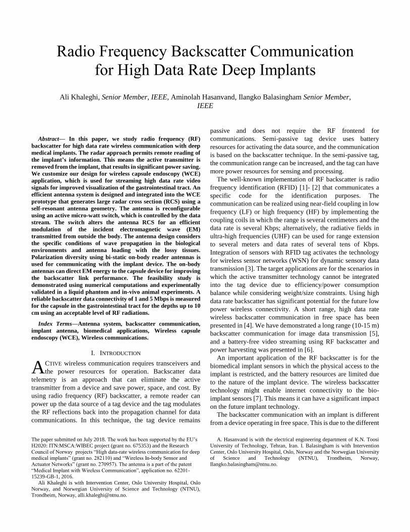
VII. BACKSCATTER ANTENNA SIMULATION AND
MEASUREMENTS
The backscatter capsule antenna is simulated in the muscle
tissue using the bi-static reader antenna configuration as shown
in Fig. 11(a). The implanted antenna is simulated in parallel to
the muscle surface. The mutual coupling between the reader
antennas is computed for the switching modes of the implant
antenna, i.e., open circuit (OC) and short-circuit (SC) states. In
the simulations, the direct coupling between the on-body
antennas is removed to discriminate the small changes caused
by the switch states. Fig. 12 shows the simulated coupling
between the reader antennas for the capsule at 50 mm depth. As
shown, the maximum reflections occur at around 600 MHz by
establishing the antenna resonance in the SC mode in which the
reflection is -70 dB, and is reduced to -90 dB in the OC mode.
The difference in the received signal is used to extract ΔRCS
for data detection, i.e. 20 dB discrimination level is observed.
The discrimination level is smaller for the frequencies away
from the resonance. Thus, the expectation is that the backscatter
works in off-resonance frequencies with degraded performance.
The amount of the peak reflection for different capsule
depths is computed in the muscle tissue. The backscatter level
(dB) reduces as a linear function of the distance with the amount
of 5.2 dB/cm. The loss slope is approximately two times (in dB)
of the path loss in the direct coupling link due to the round way
Fig. 12 Coupling between the reader antennas using SC and OC modes of the
antenna switch by removing the direct coupling for the backscatter scenario in Fig. 11(a).
Fig. 13 Simulation model of the backscatter WCE in the anatomical model of
the human body with the capsule inside the intestine and the on body reader antennas. The specified simulation box is the area used for EM computations
wave propagation.
The heterogeneous voxel model of the human body is used
for electromagnetic computations (see Fig. 13). The model is
based on the data from the Visual Human Project® of the
National Laboratory of Medicine (NLM) [32], in which the
human body is represented by voxels with a spatial resolution
of 1 mm. The voxels of the anatomical model are classified
according to their different dielectric material properties.
Thirty-two different types of biological tissues are defined in
the model. The numerical simulations are conducted using time
domain solver of CST MWS. The frequency-dependent
dielectric properties of the human tissues are used. The reader
antennas are placed on the body surface in the abdomen area,
and the capsule is in parallel to the body surface. The simulation
region is limited to the capsule and reader antenna areas as
specified in Fig. 13, to reduce the simulation time and memory.
The boundary for the selected region is a perfectly matched
layer (PML), to prevent wave propagation from the side walls
of the region into the body, except for the on body side which
is an open boundary.
The coupling value between the capsule antenna and the on
body antennas is computed in which for the capsule within the
depth of 50 mm, the coupling is -34.1 and -35.7 dB and the
capsule antenna resonance is shifted to 625 MHz. The
frequency shift compared to the muscle scenario is related to
the antenna loading with different tissues.
The backscatter link is computed by using the reader
antennas in the Voxel simulations. The attempt is to monitor the
frequencies for which the reflections are maximum and the
level of the reflections. It is observed that the backscatter
frequency is maximum at about 610 MHz with the maximum
reflection level of -70 dB for the depth of 50 mm. The
backscatter coupling increases to -62 dB for 30 mm depth. We
note that the final antenna implementation in the biological
tissues might be different from the simulations due to the
antenna loading with the tissues and the antenna integration
with the electronics inside the capsule shell. The main effect is
the change in the resonance frequency of the antenna. The point
with the capsule antenna is that the backscatter reflections can
be significant for about 24 MHz frequency deviation compared
to the optimum frequency with a maximum of 5 dB
degradations. The optimal frequency can be found using the
frequency scan option applied to the reader device.
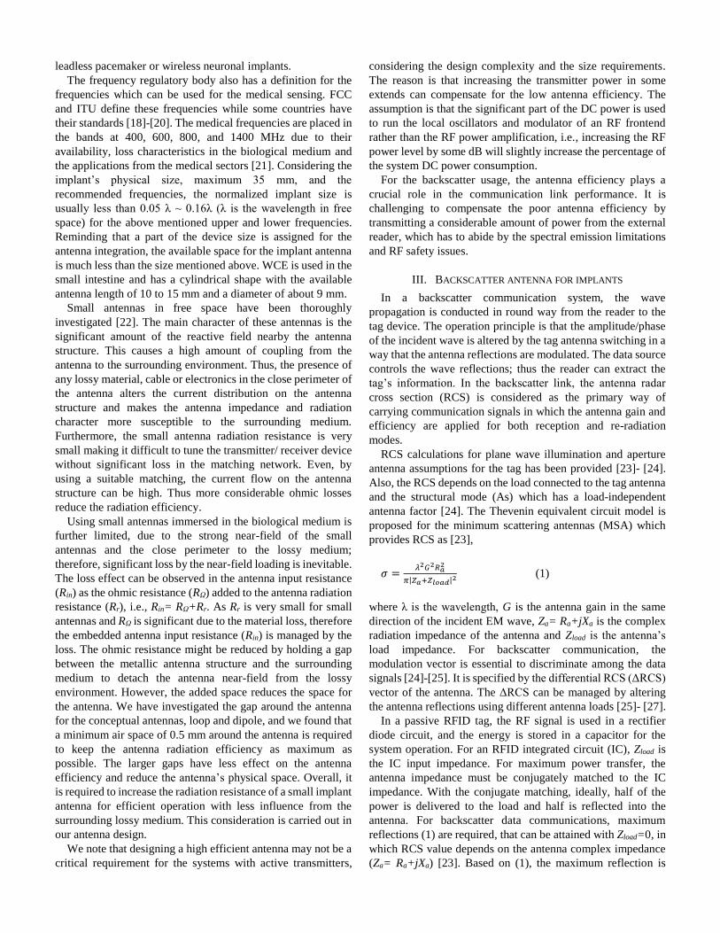
The capsule antenna has been manufactured on a flexible
Kapton dielectric with a thickness of 50 microns. The electronic
board is manufactured on a circular FR4 substrate and includes
an RF switch UPD5713TK controlled by a data source of 1 and
5 Mbps. The RF switch is used to connect or disconnect the
resonance state of the antenna. The antenna and the electronics
are integrated inside a glass shell. Fig. 14(a), (b) shows the
manufactured antenna prototypes. Fig. 14(c), (d) shows the
schematic circuit of the switch and the data source which is a
periodic {0,1} sample provided by DSC1001 oscillator circuit.
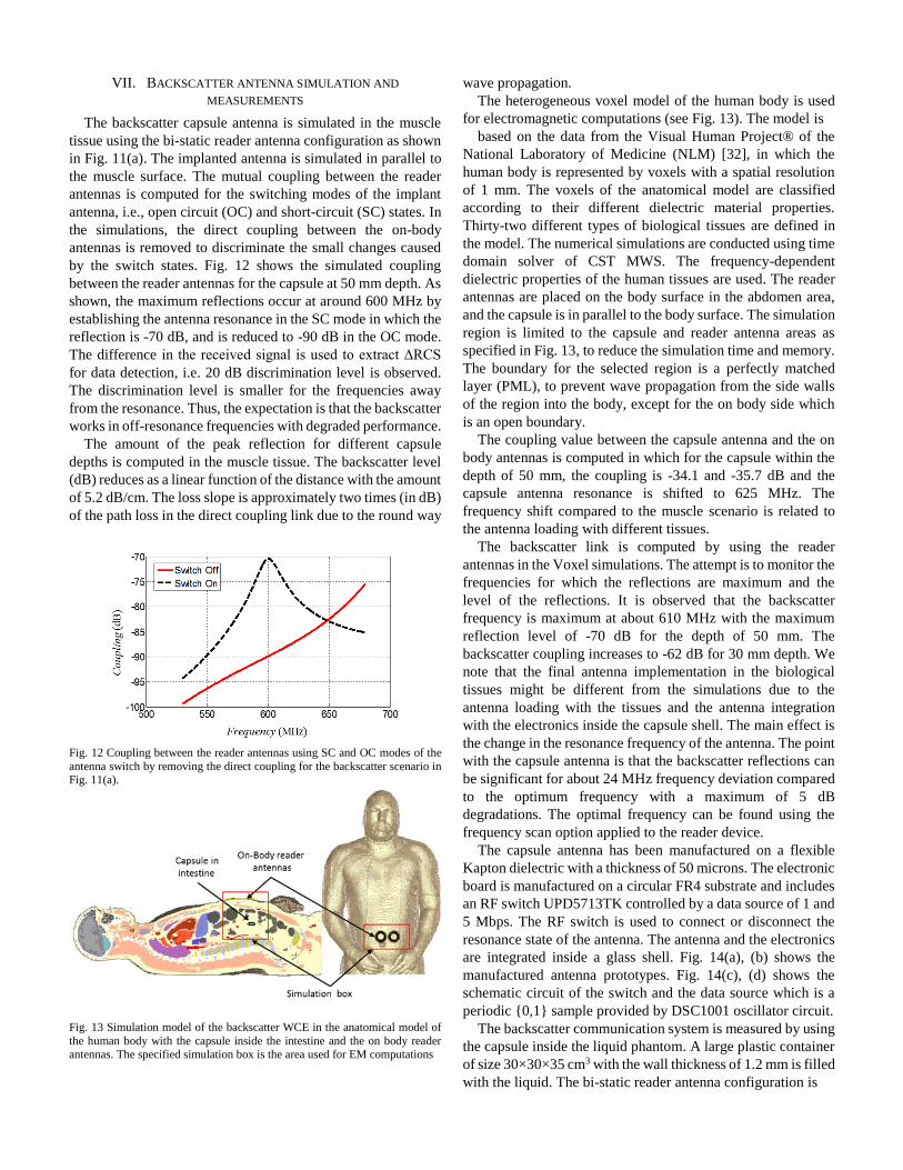
The backscatter communication system is measured by using
the capsule inside the liquid phantom. A large plastic container
of size 30×30×35 cm3 with the wall thickness of 1.2 mm is filled
with the liquid. The bi-static reader antenna configuration is
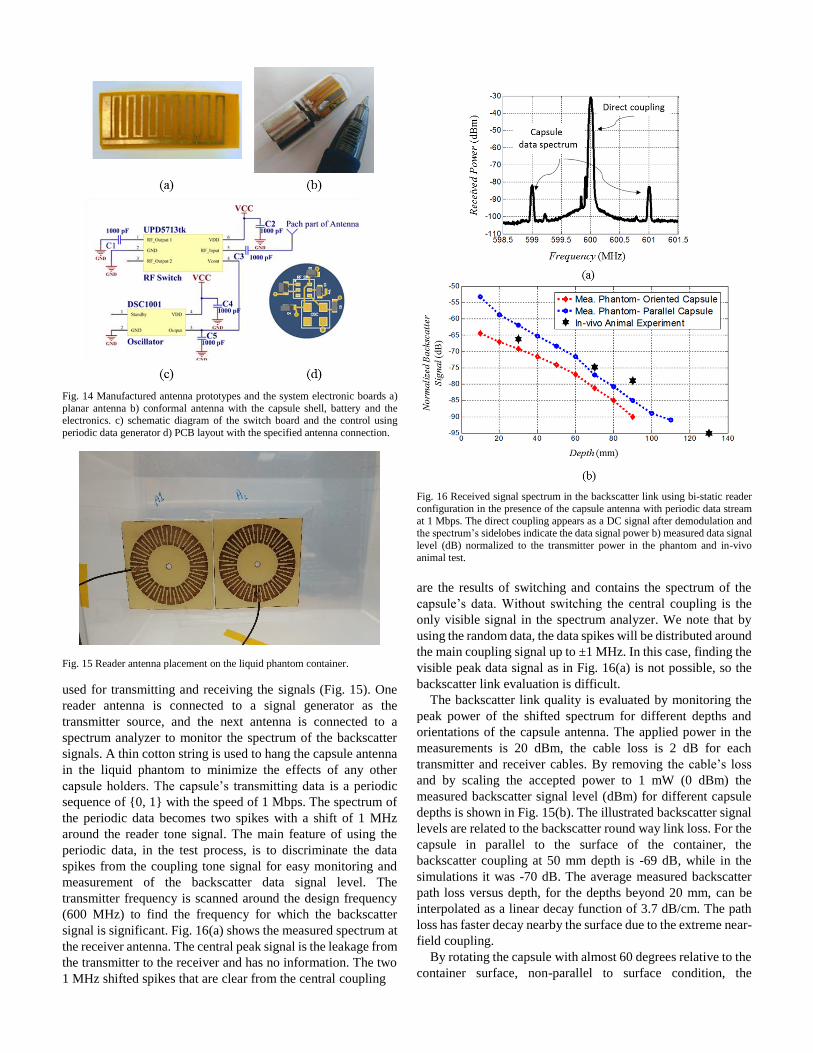
Fig. 14 Manufactured antenna prototypes and the system electronic boards a)
planar antenna b) conformal antenna with the capsule shell, battery and the electronics. c) schematic diagram of the switch board and the control using
periodic data generator d) PCB layout with the specified antenna connection.
Fig. 15 Reader antenna placement on the liquid phantom container.
used for transmitting and receiving the signals (Fig. 15). One
reader antenna is connected to a signal generator as the
transmitter source, and the next antenna is connected to a
spectrum analyzer to monitor the spectrum of the backscatter
signals. A thin cotton string is used to hang the capsule antenna
in the liquid phantom to minimize the effects of any other
capsule holders. The capsule’s transmitting data is a periodic
sequence of {0, 1} with the speed of 1 Mbps. The spectrum of
the periodic data becomes two spikes with a shift of 1 MHz
around the reader tone signal. The main feature of using the
periodic data, in the test process, is to discriminate the data
spikes from the coupling tone signal for easy monitoring and
measurement of the backscatter data signal level. The
transmitter frequency is scanned around the design frequency
(600 MHz) to find the frequency for which the backscatter
signal is significant. Fig. 16(a) shows the measured spectrum at
the receiver antenna. The central peak signal is the leakage from
the transmitter to the receiver and has no information. The two
1 MHz shifted spikes that are clear from the central coupling
Fig. 16 Received signal spectrum in the backscatter link using bi-static reader
configuration in the presence of the capsule antenna with periodic data stream
at 1 Mbps. The direct coupling appears as a DC signal after demodulation and the spectrum’s sidelobes indicate the data signal power b) measured data signal
level (dB) normalized to the transmitter power in the phantom and in-vivo
animal test.
are the results of switching and contains the spectrum of the
capsule’s data. Without switching the central coupling is the
only visible signal in the spectrum analyzer. We note that by
using the random data, the data spikes will be distributed around
the main coupling signal up to ±1 MHz. In this case, finding the
visible peak data signal as in Fig. 16(a) is not possible, so the
backscatter link evaluation is difficult.
The backscatter link quality is evaluated by monitoring the
peak power of the shifted spectrum for different depths and
orientations of the capsule antenna. The applied power in the
measurements is 20 dBm, the cable loss is 2 dB for each
transmitter and receiver cables. By removing the cable’s loss
and by scaling the accepted power to 1 mW (0 dBm) the
measured backscatter signal level (dBm) for different capsule
depths is shown in Fig. 15(b). The illustrated backscatter signal
levels are related to the backscatter round way link loss. For the
capsule in parallel to the surface of the container, the
backscatter coupling at 50 mm depth is -69 dB, while in the
simulations it was -70 dB. The average measured backscatter
path loss versus depth, for the depths beyond 20 mm, can be
interpolated as a linear decay function of 3.7 dB/cm. The path
loss has faster decay nearby the surface due to the extreme near-
field coupling.
By rotating the capsule with almost 60 degrees relative to the
container surface, non-parallel to surface condition, the
backscatter level is reduced by 12 dB in the depths close to the
surface due to the polarization mismatch. The polarization
mismatch is less within further depths due to the wave
depolarization by propagation through the medium, and the
path loss is reduced by 5 dB in 80 mm depth. By using the
capsule in a perpendicular orientation relative to the surface, the
coupling reduces by 15 dB compared to the parallel conditions.
In this orientation, it is preferred to change the placement of the
reader antennas to illuminate the capsule from different
orientations thus compensate for the polarization mismatch.
This can be done using multiple reader antennas in the final
implementation setup and switching among the transceiver
antennas for optimum backscatter signal reception.
The maximum accessible depth for the backscatter WCE
considering a typical receiver sensitivity of -90 dBm, and
maximum transmitter power of 1 mW (0 dBm) is 10 cm for the
optimum capsule-reader orientations. By considering the
polarization mismatch of 10 dB (due to the capsule rotation)
and a link margin of 10 dB, the transmitter power of 100 mW
can provide reliable link connectivity with the capsule at 10 cm.
The applied power is in the acceptable range for RF safety,
SAR.
We note that using high power in transmission may not
always be an optimum way of connectivity because of the direct
coupling to the receiver that can saturate the receiver system.
The leakage to the receiver can be further managed and reduced
by applying a portion of the transmitted power into the receiver
electronics before LNA and phase/amplitude tuning for
canceling the coupled power between the antennas. This
requires accurate phase tuning and closed-loop control
approach.
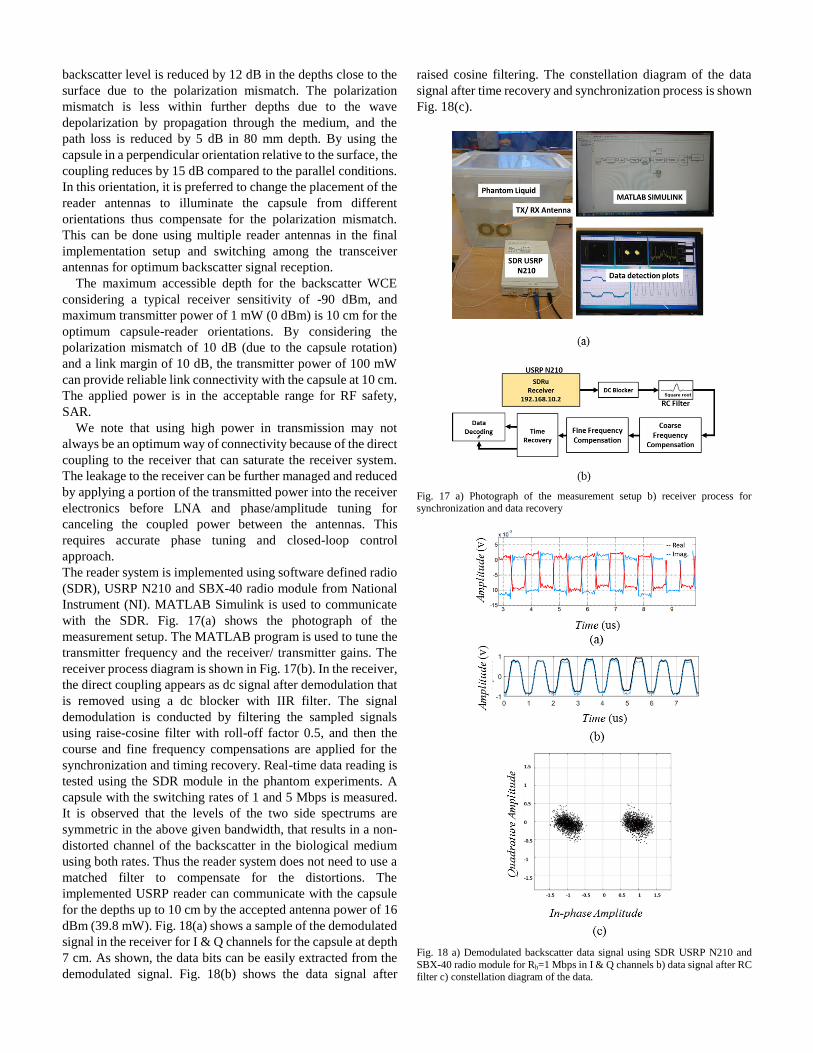
The reader system is implemented using software defined radio
(SDR), USRP N210 and SBX-40 radio module from National
Instrument (NI). MATLAB Simulink is used to communicate
with the SDR. Fig. 17(a) shows the photograph of the
measurement setup. The MATLAB program is used to tune the
transmitter frequency and the receiver/ transmitter gains. The
receiver process diagram is shown in Fig. 17(b). In the receiver,
the direct coupling appears as dc signal after demodulation that
is removed using a dc blocker with IIR filter. The signal
demodulation is conducted by filtering the sampled signals
using raise-cosine filter with roll-off factor 0.5, and then the
course and fine frequency compensations are applied for the
synchronization and timing recovery. Real-time data reading is
tested using the SDR module in the phantom experiments. A
capsule with the switching rates of 1 and 5 Mbps is measured.
It is observed that the levels of the two side spectrums are
symmetric in the above given bandwidth, that results in a non-
distorted channel of the backscatter in the biological medium
using both rates. Thus the reader system does not need to use a
matched filter to compensate for the distortions. The
implemented USRP reader can communicate with the capsule
for the depths up to 10 cm by the accepted antenna power of 16
dBm (39.8 mW). Fig. 18(a) shows a sample of the demodulated
signal in the receiver for I & Q channels for the capsule at depth
7 cm. As shown, the data bits can be easily extracted from the
demodulated signal. Fig. 18(b) shows the data signal after
raised cosine filtering. The constellation diagram of the data
signal after time recovery and synchronization process is shown
Fig. 18(c).
Fig. 17 a) Photograph of the measurement setup b) receiver process for synchronization and data recovery
Fig. 18 a) Demodulated backscatter data signal using SDR USRP N210 and
SBX-40 radio module for Rb=1 Mbps in I & Q channels b) data signal after RC filter c) constellation diagram of the data.

Fig. 19 a) Photograph of OR for animal experiments at the Intervention Center, Oslo University Hospital b) illustration of the capsule antenna insertion into the
animal abdomen through a small incision for in-vivo backscatter measurements.
The receiver sensitivity is calculated for the SBX-40 radio
assuming OOK demodulation [33]. The receiver noise figure
(NF) is 5 dB, the required energy per bit to the noise power
spectral density (Eb/No) is 14 dB for BER=10-6. The IF
bandwidth of the receiver is 25 MHz and the data rates are 1
and 5 Mbps. The data filter bandwidth is raised cosine with roll-
off factor 0.5. The calculated receiver sensitivity for the data
rate of 1 Mbps is -92 dBm and for 5 Mbps is -87 dBm. We note
that the receiver sensitivity can be improved by using an
external LNA with lower NF or accepting lower BER=10-3.
Referring to Fig. 16(b) we can calculate the communication
depth based on the calculated receiver sensitivity for the given
data rates by applying 1 mW of the power.
The in-vivo animal experiments are conducted on a pig
weighing 61 Kg. To evaluate and compare the performance of
the capsule in an environment similar to that of the human body,
the pig is prepared under a general anesthetic in the operating
room of the Intervention Centre, Rikshospitalet, Oslo
University Hospital, Norway. The center has accreditation for
conducting animal experiments. All the experiments are
performed in strict compliance with laws regarding Ethic
standards and humane treatment of animals. Because this
animal was alive and all of its organs were operating normally,
the experimental conditions were virtually identical to the
conditions expected in a human body.
First, the capsule is inserted through an incision in the animal
abdomen and placed close to the abdomen surface at about 3
cm depth (see Fig. 19(b)). The transmitter frequency is swept
around 600 MHz to find the frequency for which the maximum
backscatter is observed. The optimum backscatter frequency is
found at around 597 MHz, instead of the designed 604 MHz.
The reason is the different material surrounding the capsule in
the in-vivo experiments compared to the liquid phantom and
muscle/Voxel tissue simulations. Even though we can read the
capsule signal at 604 MHz, but the backscatter signal level is 2
dB less than the optimum read frequency.
The capsule device is placed in more depths in the abdomen
of the animal among the intestine tissues on the external surface
of the intestine. We did not cut the small intestine for inserting
the capsule as it might place the animal in an unstable condition.
The incisions are closed to prevent any leakage of the signal
through the holes. Similar to the phantom experiments, the
reader antennas are placed on the surface of the abdomen above
the approximate location of the capsule. The placement and
orientations of the capsule are not well under control due to
movements of the intestine and the capsule during the
experiment. So it is difficult to evaluate the exact depth and
rotation of the capsule. Trials are conducted to measure
approximate depth. The measured results are qualitative and
show the feasibility of wireless backscatter connectivity in the
in-vivo tests. The reader antennas are placed and moved on the
abdomen surface to obtain the backscatter signal from the
capsule. The antennas are not necessarily in a flat surface due
to the shape of the abdomen and the elasticity of the tissues. The
rotation of the reader antennas is changed to obtain the
maximum data signal level, i.e., the reader polarization is
manually tuned. The received power is directly visualized using
the spectrum analyzer by transmitting 20 dBm of the power in
which 4 dB is related to the loss of the cable. The backscatter
signal level by scaling the accepted power to 0 dBw, is depicted
in Fig. 16(b) for the approximate measurement depths at 30, 70,
90, 130 mm. The in-vivo signal level is approximately (±5 dB)
matched to the liquid phantom measurements. The deviation is
mainly because of the unknown orientation of the capsule, the
reader antennas’ placement on the animal body, and the
accuracy of the in-vivo setting
VIII. CONCLUSION
Radio frequency backscatter is used for high data rate deep
implant wireless communications. The backscatter eliminates
the power-hungry transmitter unit from the implant device and
can save several 10’s of mW power in the implant unit that
makes high data rate and continues connectivity feasible for
improved visualization of the small intestine. To succeed with
the deep implant backscatter, the implant antenna and the
external reader antennas are precisely designed for the
biological medium. Loop antenna geometry is applied to both
the internal and external antennas.
The capsule antenna of length 11.5 mm and diameter 9 mm,
has a meander loop geometry with a capacitive feed mechanism
for generating a resonance frequency with less influence from
the surrounded biological tissues. The antenna is fabricated
using a flexible substrate material and is integrated into the
perimeter of a cylindrical capsule device. The antenna
resonance is at 600 MHz, and the radiations are dual polar. The
antenna RCS is controlled using active switching of the antenna
modes.
Bi-static on body antennas are designed and used for wireless
communications. The reader antennas have meander loop
geometry to reduce the overall size and are self-matched at 600
MHz frequency. The reader antennas are linear polarized and
are used in a side-by-side configuration to communicate with
the implant capsule. Orthogonal polarizations reduce the
coupling between the nearly spaced reader antennas. The
meander loop antennas have the maximum radiation in their
main axes direction and can forward the power to the internal
body with an acceptable level of SAR.
The backscatter link is established using the bi-static reader.

The link is computed using numerical simulations and is
measured in a liquid phantom. The backscatter path loss versus
depth is extracted by implementing a periodic data stream in the
capsule device. A linear path loss as a function of depth is
obtained for both phantom liquid and homogenous muscle
tissues. The computed average backscatter path loss in the
muscle tissue is 5.2 dB/cm and in the liquid phantom mimicking
the average body tissues is 3.75 dB/cm. The backscatter WCE
is tested in the in-vivo animal experiments to validate the
operation of the system. We have shown a very consistent link
for the depths up to 13 cm with a moderate reader power up to
250 mW and data rates of 1 and 5 Mbps. The power level shall
be changed considering the received signal level to minimize
the SAR. In the in-vivo test, we use a frequency scan around the
design frequency to compensate for the possible resonance
frequency shift of the implant antenna due to the bio-material
loading. A communication system is realized using SDR and
the demodulated data signals and constellation diagrams are
presented.
ACKNOWLEDGMENT
The authors thank surgeon J. Bergsland and the surgical team
for performing the animal experiment at the Intervention
Center, Oslo University Hospital.
REFERENCES
[1] R. B. Green, “The general theory of antenna scattering,” Report No. 1223-
17, Electron Science Laboratory, Columbus, OH, Nov, 1963. [2] P.V Nikitin, K.V.S. Rao, “Theory and measurement of backscattering
from RFID tags,” IEEE Ant. Propag. Mag., vol 48 , no.6, pp. 212 – 218,
Dec. 2006. [3] M. Buettner, B. Greenstein, A. Sample, J. R. Smith, and D. Wetherall,
“Revisiting smart dust with RFID sensor networks,” in Proc2008 ACM Workshop on Hot Topics in Networks, Oct. 2008.
[4] R. Correia and N. B. Carvalho, "Ultrafast backscatter modulator with low-
power consumption and wireless power transmission capabilities," in IEEE Microwave and Wireless Components Letters, vol. 27, no. 12, pp.
1152-1154, Dec. 2017.
[5] A. Hasanvand, A.Khaleghi, I. Balasingham “Coherent query scheme for wireless backscatter communication systems with single tag”, EURASIP
Journal on Wireless Communications and Networking, vol. 2018, 2018.
[6] S. Naderiparizi, M. Hessar, V. Talla, S. Gollakota, and J. R. Smith. “Towards batteryfree hd video streaming”, 15th USENIX Symp. On
Networked Systems Design and Implementation (NSDI), April 9-11, 2018,
Renton, WA, USA. [7] Vikram Iyer, Vamsi Talla, Bryce Kellogg, Shyamnath Gollakota, Joshua
R Smith, “Inter-technology backscatter: towards internet connectivity for
implanted devices” In proceedings of the 2016 ACM SIGCOMM Conference (SIGCOMM 2016), August 2016.
[8] H. Aubert, “RFID technology for human implant devices” Comptes
Rendus Phys., vol. 12, no. 7, pp. 675–683, Sep. 2011. [9] J. S. Besnoff and M. S. Reynolds, “Near field modulated backscatter for
in vivo biotelemetry,” 2012 IEEE International Conference on RFID
(RFID), pp. 135–140, May. 2012. [10] E. Moradi et al., “Backscattering neural tags for wireless brain-machine
interface systems,” IEEE Trans. Antennas Propag., vol. 63, no. 2, pp.
719– 726, Feb. 2015. [11] A. Sample, D. Yeager, P. Powledge, and J. Smith, “Design of a passively
powered, programmable sensing platform for UHF RFID systems,” in
Proc. 2007 IEEE International Conference on RFID, pp. 149–156 [12] Stewart J. Thomas, Jordan S. Besnoff, and Matthew S. Reynolds.
“Modulated backscatter for ultra-low power uplinks from wearable and
implantable devices” In Proceedings of the 2012 ACM workshop on Medical communication systems (MedCOMM '12). ACM, New York,
NY, USA, 1-6.
[13] H. Cao, V. Landge, U. Tata, Y.-S. Seo, S. Rao, S.-J. Tang, H.F. Tibbals,
S. Spechler, and J.-C. Chiao, “An implantable, batteryless and wireless capsule with integrated impedance and ph sensors for gastroesophageal
reflux monitoring,” IEEE Trans. on Biomedical Engineering, vol. 59, no.
11, pp. 3131-3139, 2012. [14] J. Riistama, E. Aittokallio, J. Verho, and J. Lekkala, “Totally passive
wireless biopotential measurement sensor by utilizing inductively coupled
resonance circuits,” Sens. Actuators A, Phys., vol. 157, no. 2, pp. 313–321, Feb. 2010.
[15] R. Lodato, V. Lopresto, R. Pinto, and G. Marrocco, “Numerical and
experimental characterization of through-the-body UHF-RFID links for passive tags implanted into human limbs,” IEEE Trans. Antennas
Propag., vol. 62, no. 10, pp. 5298–5306, Oct. 2014.
[16] H. N. Schwerdt et al., “A fully passive wireless microsystem for recording of neuropotentials using RF backscattering methods,” J.
Microelectromech. Syst., vol. 20, pp. 1119–1130, Oct. 2011.
[17] S.Gabriel, R.W.Lau and C.Gabriel: The dielectric properties of biological tissues: II. Measurements in the frequency range 10 Hz to 20 GHz, Phys.
Med. Biol. 41 (1996), 2251-2269.
[18] Technical and operating parameters and spectrum use for short-range radio communication devices, International Telecommunication Union.
[Online]. Available: www.itu.int/pub/ R-REP-SM.2153-2- 2011.
[19] ETSI EN 301 839-1, European Telecommunications Standards Institute, 2007. Online Available: http://www.etsi.org/deliver /etsi_en/
301800_301899/ 30183901/01.03.01_60/en_ 30183901v010301p.pdf
[20] Federal Communications Commission, 47 CFR 95.601-95.673 Subpart E, 1999. [Online]. Available: http://wireless.fcc.gov/services/index.htm?job
=operations&id=medical_implan [21] A. Khaleghi, I. Balasingham, “Power coupling for conceptual antennas in
medical implant applications”, 11th European Conference on Antennas
and Propagation (EUCAP) 2017, 19-24 March 2017, Paris France [22] Harrington, R. F.. “Effect of antenna size on gain, bandwidth, and
efficiency” J. Res. Nat. Bur. Stand 64 , no. 1 (1960): 1-12.
[23] P. V. Nikitin and K. V. S. Rao “Theory and measurement of backscattering from RFID tags,” IEEE Antennas Propag. Mag., vol. 48,
no. 6, Dec. 2006
[24] A. Bletsas, A. G. Dimitriou, and J. N. Sahalos “Improving backscatter radio tag efficiency,” IEEE Trans. Microw. Theory Techn., vol. 58, no. 6,
pp. 1502–1509, Jun. 2010.
[25] S. Ebrahimi-Asl, M. Tayeb Ghasr, M. J. Zawodniok “Design of Dual-Loaded RFID Tag for Higher Order Modulations” IEEE Trans. Microw.
Theory and Techn., vol. 66, Iss. 1, pp. 410 – 419, Jan. 2018
[26] L. A. Muth, C. M. Wang, and T. Conn, “Robust separation of background and target signals in radar cross section measurements,” IEEE Trans.
Instrum. Meas., vol.54, no.6, pp. 2462-2468, 2005.
[27] C.C.Yen , A. E. Gutierrez, D. Veeramani, D. Weide, “Radar cross-section analysis of backscattering RFID tags” IEEE Antennas and Wireless
Propagation Letters, vol. 6 , pp. 279 – 281, 2007.
[28] R.Chavez-Santiago, A. Khaleghi, I. Balasingham “Matching layer for path loss reduction in ultra wideband implant communications”
Engineering in Medicine and Biology Society (EMBC), 36th Annual
International Conference of the IEEE, pp. 6989-6992, 2014. [29] T. Yousefi and R. E. Díaz, “Pushing the limits of radiofrequency (RF)
neuronal telemetry,” Sci. Rep., vol. 5, p. 10588, Jun. 2015.
[30] A. Khaleghi, I. Balasingham, R. Chávez-Santiago “An ultra-wideband wire spiral antenna for in-body communications using different material
matching layers”, Engineering in Medicine and Biology Society (EMBC),
2014 36th Annual International Conference of the IEEE, pp. 6985-6988,
Aug. 2014.
[31] RF exposure evaluation report for sproutling smart sleep wearable-hub,
Model Number FNF59, FCC ID: PIYFNF59-17A5H, Report No. 17020160HKG-001, available online, https://fccid.io/PIYFNF59-
17A5H/RF-Exposure-Info/SAR-3562352.
[32] E. Gjonaj, M. Bartsch, M. Clemens, S. Schupp, and T. Weiland, “High-resolution human anatomy models for advanced electromagnetic field
computations,” IEEE Trans. Magn., vol. 38, no. 2, pp. 357-360, Mar.
2002. [33] Calculating the Sensitivity of an ASK Receiver, APPLICATION NOTE
2815, Maxim Integrated, Nov 05, 2003.

Ali Khaleghi (M’02, SM’14) received
Ph.D. in Physics from the University of
Paris XI, Paris, France in 2006. From
2006 to 2007, he was postdoc at the
Institute d' Electronique et de
Télécommunications de Rennes (IETR),
France. From 2008 to 2009 was postdoc
at the Intervention Center (IVS), Oslo
University Hospital, Norway. From 2010
to 2015, he was assistant professor in the Electrical and
Computer Engineering Department at K. N. Toosi University
of Technology (KNTU), Tehran, Iran. He obtained several
research and industrial grants during his career at KNTU. He
established Wireless Terminal Test Lab (WTT) at KNTU. He
distinguished as the best researcher of KNTU in 2013. From,
2015, he is an adjunct professor at KNTU and scientist at the
Norwegian University of Science and Technology (NTNU) and
Oslo University Hospital. His research field is on antennas and
waves propagation, wireless communications, electromagnetic
compatibility (EMC), measurement techniques and bio-
electromagnetics. He has authored over 90 journal and full
conference papers and hold 4 international patents. He is a
Senior IEEE Member.
Aminolah Hasanvand received MSc in
electronics and telecommunication
engineering from the University of Tabriz,
Tabriz, Iran, in 2007. He has 8 years of
experience in wireless communications.
He is Ph.D. student at the electrical
engineering department at K. N. Toosi
University of Technology, Tehran, Iran. His main research
interests include wireless backscatter communications, passive
RFID, in-body wireless sensor communication systems, and
software defined radio implementations.
Ilangko Balasingham (M’98, SM’11)
received the M.Sc. and Ph.D. degrees
from the Department of Electronics and
Telecommunications, Norwegian
University of Science and Technology
(NTNU), Trondheim, Norway in 1993 and
1998, respectively, both in signal
processing. He performed his Master’s
degree thesis at the Department of Electrical and Computer
Engineering, University of California Santa Barbara, USA.
From 1998 to 2002, he worked as a Research Engineer
developing image and video streaming solutions for mobile
handheld devices at Fast Search & Transfer ASA, Oslo,
Norway, which is now part of Microsoft Inc. Since 2002 he has
been with the Intervention Center, Oslo University Hospital,
Oslo, Norway as a Senior Research Scientist, where he heads
the Wireless Sensor Network Research Group. He was
appointed as a Professor in Signal Processing in Medical
Applications at NTNU in 2006. For the academic year
2016/2017 he was Professor by courtesy at the Frontier
Institute, Nagoya Institute of Technology in Japan. His research
interests include super robust short range communications for
both in-body and on-body sensors, body area sensor network,
microwave short range sensing of vital signs, short range
localization and tracking mobile sensors, and nanoscale
communication networks. He has authored or co-authored over
225 journal and conference papers, 7 book chapters, 42
abstracts, 6 patents, and 20 articles in popular press. Ilangko has
given 16 invited/ keynotes at the international conferences. In
addition, he is active in organizing conferences (Steering
Committee Member of ACM NANOCOM 2018-2021; General
Chair: the 2019 IEEE Int. Symposium of Medical ICT, the 2012
Body Area Networks (BODYNETS) conference; TPC Chair of
the 2015 ACM NANOCOM) and editorial board (Area Editor
of Elsevier Nano Communication Networks 2013-unti now).
He is a Senior IEEE Member.