radio engineering · transit tine effects in gap 4 construction of inductive- output tube 6...
TRANSCRIPT

ADVANCED
PRACTICAL
RADIO ENGINEERING
TECHNICAL ASSIGNMENT
SPECIAL ULTRA HIGH FREQUENCY TUBES
Copyright 1949 by
Capitol Radio Engineering Institute
Washington, D. C.
1256 El
w
- TABLE OF CONTENTS -
SPECIAL ULTRA HIGH FREQUENCY TUBES
Page
INTRODUCTION 1
INDUCTIVE - OUTPUT TUBE - FUNDAMENTAL THEORY 1
ACTION OF ELECTRON BEAM ON A RESONANT CAVITY 2
REACTION OF RESONATORS ON ELECTRON BEAN 4
TRANSIT TINE EFFECTS IN GAP 4
CONSTRUCTION OF INDUCTIVE- OUTPUT TUBE 6
OPERATING FEATURES 9
THE KLYSTRON TUBE 10
TYPICAL CONSTRUCTION OF A KLYSTRON TUBE 11
FUNDAMENTAL ACTION OF THE KLYSTRON TUBE 13
KLYSTRON AMPLIFIER 17
GENERALIZED BEHAVIOR 18
KLYSTRON TUBE PERFORMANCE 19
KLYSTRON FREQUENCY MULTIPLICATION 19
FREQUENCY ADAPTABILITY 22
DEBUNCHING 22
SIGNAL -TO -NOISE CONSIDERATIONS 23
OVER -BUNCHING AND UNDER -BUNCHING 24
KLYSTRON OSCILLATORS 25
KLYSTRON REGULATED POWER SUPPLIES 31
FREQUENCY VARIATIONS 33
KLYSTRON TUNER 34
METHOD OF TUNING ADJUSTMENT 34
THE REFLEX KLYSTRON 35
METHODS OF MODULATION 36
THE MAGNETRON 37
ORIGINAL DEVELOPMENT 37
NOTION IN A MAGNETIC FIELD 38
ACTION OF A COMBINED ELECTRIC AND MAGNETIC FIELD 39
DISCUSSION OF MOTION 40
SPLIT -PLATE MAGNETRON 42
ADDITIONAL FACTORS OF OPERATION 44
ELECTRONIC OSCILLATIONS OF HIGHER ORDER 45
CATHODE HEATING 46

2
Page
MAGNETRONS WITH CAVITY RESONATORS 46
PERFORMANCE OF FOUR- CAVITY MAGNETRON 47
DISCUSSION OF CAVITY RESONATOR 48
ADVANTAGES AND DISADVANTAGES OF THE MAGNETRON TUBE 50
CONCLUSIONS 50
I
I
I
1
I
I I
i I I
I
I I
I I
i i
v
1
SPECIAL ULTRA HIGH FREQUENCY TUBES
S COPE OF ASSIGNMENT
In the preceding assignment, the modifications required in the design of the negative grid tube to enable it to operate satisfactorily at ultra -high frequencies, were taken up, and it was seen how by supporting the electrodes directly on their lead -ins, by making the latter shorter and of greater cross section, and by reducing the clear- ances between electrodes, the tube's operation could be extended to the higher frequencies.
Ultimately, however, a fre- quency limit is reached beyond which negative grid tubes will fail to
operate. The greater the power out- put desired, the lower is the limit- ing frequency. If power at higher frequencies is desired, it is clear that a radically different type of tube will be necessary. Such tubes have been developed, and are the subject matter of this assignment. Three basic tubes are discussed: The inductive- output tube, the Klystron, and the magnetron.
I NDUCTIVE-OUTPUT AMPLIFIER
It has been shown how transit - time effects produce input loading in a vacuum tube, and that by re- ducing the tube dimensions, as in the acorn tube, the loading may be substantially reduced. This re- duction in the size of the tube, however, decreases its ability to radiate or otherwise dispose of its internal losses, particularly plate dissipation, and thus reduces its power -handling ability. This is one
of the major restrictions in u. h. f.
technique.
Suppose that one attempted to
reduce the transit time by increas- ing the plate voltage. While such increase would be effective, it too
would increase the plate dissipa- tion and thus limit the power -hand- ling capability of the tube. The reason is that the electrons would attain higher velocities--thus de- creasing the transit time--but at the same time causing them to strike the plate with greater force and thus heating it up more.
INDUCTIVE - OUTPUT TUBE- FUNDA- MENTAL THEORY.--An ingenious solu- tion to this problem and other prob- lems of u. h. f. tube operation is the inductive -output tube, developed by Haeff and Nergaard.' In this tube the control grid is spaced close to the cathode. This increases the transconductance to a greater extent than the input capacity, and thus affords in itself a distinct advantage. In addition, the closer spacing cuts down the cathode -to- grid transit time and hence also the input loading, i.e., makes 11, great- er.
The next feature is to have the electron stream within the tube di- rectly affect a resonant circuit surrounding the stream. Actually the resonant circuit is a kind of resonant cavity that can be directly actuated by the electron stream, and at a point where the electron velo- city is high. This high velocity is brought about by placing cylin- drical electrodes in the tube
*See "A Wide -Band Inductive -Gut- put Amplifier," Haeff and Nergaard, I.R.E. Proc., March 1940.

2 SPECIAL ULTRA HIGH FREQUENCY TUBES
through which the electrons shoot, and placing a high positive poten- tial (about 3,600 volts) on these electrodes.
Then, farther on in the tube beyond these electrodes and the resonant cavity, the electrons are
decelerated by a collector anode at a lower potential (about 1,500 to
2,000 volts) upon which they im- pinge. The deceleration causes them
to strike the collector with less
force than they could strike an
electrode at 3,600 volts, and there-
fore causes considerably less losses.
As a result the output may be as
high as from 9 watts Class C tele-
phone, up to 35 watts class C tele-
graphy at 500 mc, with an efficiency
of 60 %! Operation up to 1,000 mc is
not improbable at the time of writ- ing.
ACTION OF ELECTRON BEAM ON A RESONANT CAVITY. -Before going into a more detailed discussion of the tube it will be of value to analyze
the action of an electron beam upon
a resonant cavity. This action occurs not only in the inductive output tube, but also in the Klys- tron and magnetron tubes to be
discussed farther on.
Consider a cavity resonator of
the reentrant type, formed of two concentric shells, as shown in
Perspective in Fig. 1(A) and in
cross section in (B). It will be
observed that the inner cylinder is
interrupted along its length to form
a gap or aperture. It is in this region that electrons shooting through the gap induce charges in the interior of the cavity resona-
tor.
Consider an electron momen- tarily at position a as it moves from left to right through the inner
cylinder en route to the collector anode (not shown). At a it induces
positive charges on the inner wall
of the inner cylinder, and these positive charges are linked to the
electron by electric field lines, as shown.
While some very few lines ex- tend from the electron over to the
gap and into the cavity space, the
effect is negligible and the posi-
tive charges may be assumed to be all
within the inner tube and close to
the electron. As the electron moves
to the right, the positive charges and the connecting electric field move with it, so that a positive charge is approaching the gap.
On the other hand, when the electron is at point c, the induced
positive charge is moving away from
the gap. Hence, if there are at any moment substantially as many elect-
rons at c as there are at a, the
rate at which the positive charge builds up at the gap owing to electrons coming from a is just balanced by the rate at which the
positive charge is decreased by
electrons receding from the gap through point c, and the two effects
cancel. Since rate of change of charge represents current, one can say that the moving electrons at a
and at c cancel each other's current inducing effects at the gap. How- ever, even if only one electron is under consideration, the effect at
the gap is small until the electron
is in the gap region.
Now consider an electron in the gap at point b. As it moves to the
right, the positive induced charge at the left -hand edge of the gap is
decreasing, and that at the right - hand edge of the gap is increasing. This is exactly the same condition as was discussed previously in the case of a diode, where electrons are moving from the cathode to the plate, so that a decreasing induced posi-
i
i
1
1
1
1
1
1
1
1

INDUCTIVE- OUTPUT AMPLIFIER
tive charge occurs at the cathode, and an increasing induced positive charge occurs at the plate. It will
be recalled that this represents an electron current flow into the cathode and an electron current flow out of the plate.
In a similar manner a momentary current flow occurs within the cavi- ty space, as represented by the two
Electron
Beam
Fig. 1(A).- Perspective view of re-
entrant -type cavity resonator.
curved arrows, while the electron is
in transit through the gap region.
lf, however, other electrons are present, both ahead and behind the
one under consideration in a con- tinuous stream of uniform density, then the above momentary current flow within the cavity space does not occur. This is because as fast
as any one electron moves from one point of the gap to the next, an electron behind it replaces it in
its previous position, and, as a re-
sult, the induced positive charge at each end of the gap does not change. Since only a varying charge represents a current flow, no cur- rent flows under these conditions.
In this sense the cavity reso- nator differs from the diode, where
a uniform electron stream can pro- duce a continuous current flow. The
3
reason is that in the case of the
diode the electrons induce charges only after they have left the cath-
ode and until they have reached the
plate; whereas here the electrons are never in the metal, and hence at
all times are able to induce charges
and thus interfere with each other's
actions.
Thus one arrives at the final
Fig. 1(B).--Cross-section of re- entrant -type cavity resonator.
conclusion that the mere passage of a continuous uniform stream or beam of electrons through a gap in a
cavity resonator does not produce charging currents in the resonator.
On the other hand, when one electron
alone is considered, a momentary flow is obtained in the resonator as the electron passes through the gap. This is because one electron cannot be considered a steady, uniform beam.
Hence if the beam can be broken up or modulated into regions or portions containing a greater density of electrons and alternate regions having alesser density of electrons, so that the stream is no longer uni- form, currents will be set up in
the resonator first in one direction
and then in the other; in short, alternating currents can be induced
4 SPECIAL ULTRA HIGH FREQUENCY TUBES
in the resonator. If these alter-
nate high and low electron densities
follow one another at the right rate,
they will be in time or resonance with the natural frequency of the resonator and excite it to a high degree.
Such 'bunching' of the elect- rons can be produced in several ways. In the inductive output it is
achieved by the action of the con- trol grid, which acts in the same manner as in an ordinary vacuum tube
i.e., as a gate that permits more or less electrons to pass through it
in accordance with the impressed signal voltage. If the frequency of
the latter coincides with the reson-
ant frequency of the resonator, then
the bunching will be at the right sequence to excite the resonator strongly. Output energy can then be
extracted from the resonator in a
variety of ways, such as by means of
a small coupling loop (described in
a previous assignment).
REACTION OF RESONATOR ON ELEC- TRON BEAN.--As the groups of elec- trons pass by the gap and induce currents in the resonator, they set
up an a -c voltage across the gap
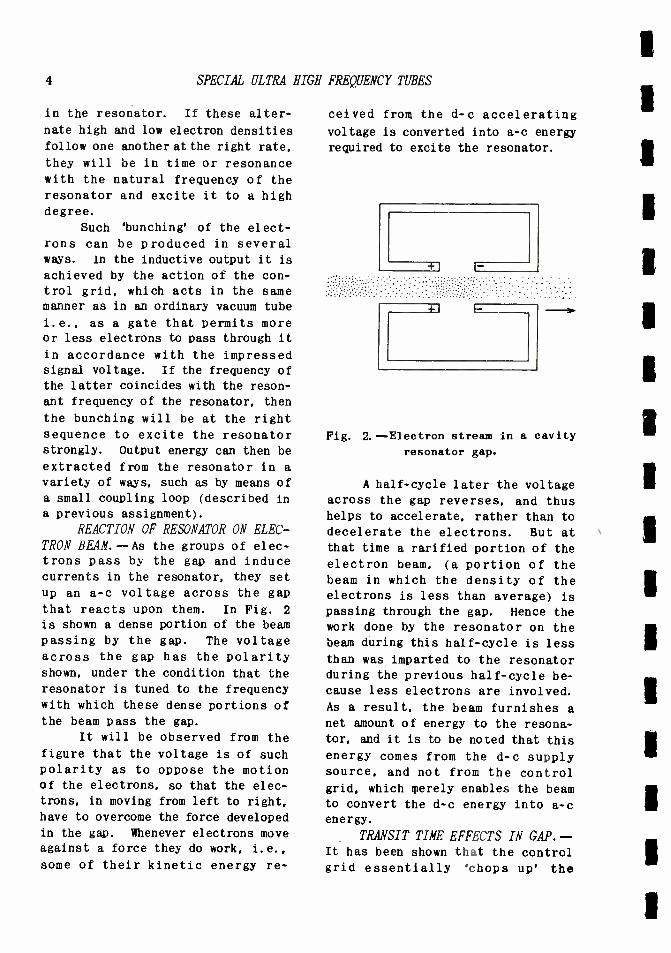
that reacts upon them. In Fig. 2
is shown a dense portion of the beam
passing by the gap. The voltage across the gap has the polarity shown, under the condition that the resonator is tuned to the frequency with which these dense portions of the beam pass the gap.
It will be observed from the
figure that the voltage is of such
polarity as to oppose the motion of the electrons, so that the elec-
trons, in moving from left to right,
have to overcome the force developed
in the gap. Whenever electrons move against a force they do work, i.e.,
some of their kinetic energy re-
ceived from the d -c accelerating
voltage is converted into a -c energy
required to excite the resonator.
Fig. 2.-- Electron stream in a cavity
resonator gap.
A half -cycle later the voltage
across the gap reverses, and thus helps to accelerate, rather than to
decelerate the electrons. But at that time a rarified portion of the electron beam, (a portion of the beam in which the density of the electrons is less than average) is
passing through the gap. Hence the work done by the resonator on the
beam during this half -cycle is less
than was imparted to the resonator during the previous half -cycle be- cause less electrons are involved.
As a result, the beam furnishes a
net amount of energy to the resona- tor, and it is to be noted that this energy comes from the d -c supply source, and not from the control grid, which merely enables the beam to convert the d -c energy into a -c energy.
TRANSIT TIME EFFECTS IN GAP. - It has been shown that the control grid essentially 'chops up' the
INDUCTIVE- OUTPUT AMPLIFIER
electron beam into dense and rari- fied portions. The length of these alternate portions depends in-
versely upon the frequency of the
signal voltage impressed upon the
grid, and directly upon the velocity
of the beam. Thus, the distance be-
tween two successive dense or two rarefied portions of the beam may be regarded as an electron beam wave length of a sound wave, or of a
radio wave.
The ratio of this quantity to
the gap length is important in
evaluating the effectiveness of the beam in setting up oscillations in
the resonator. If the gap length is
comparable to the above beam wave length, transit -time effects very similar to those in an ordinary diode are encountered, and the efficiency of operation is reduced.
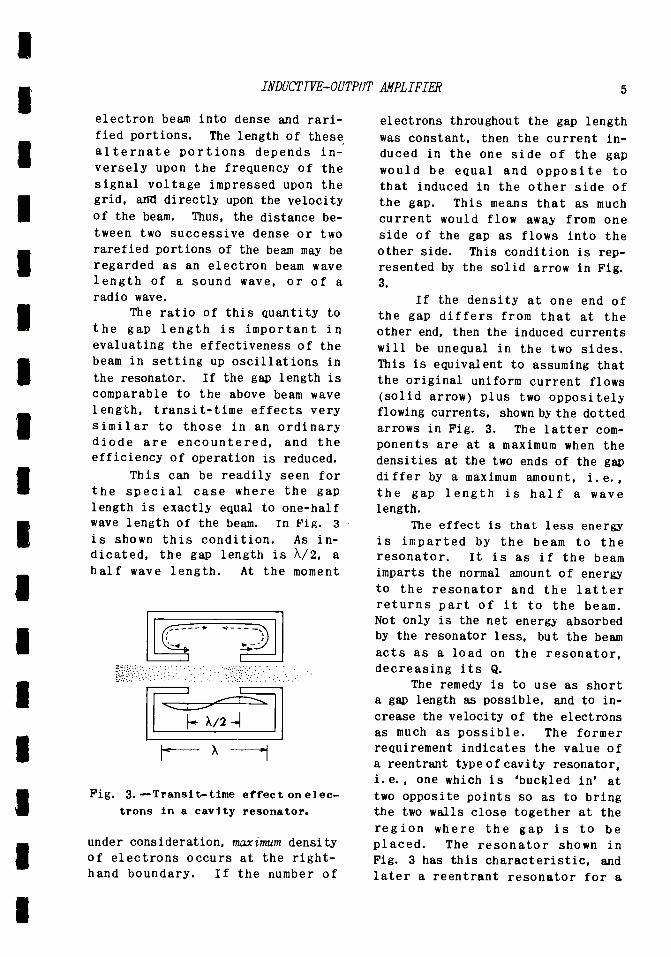
This can be readily seen for
the special case where the gap
length is exactly equal to one -half wave length of the beam. In Fig. 3
is shown this condition. As in-
dicated, the gap length is N /2, a
half wave length. At the moment
1-1- X/2 -.I
X - Fig. 3. -- Transit -time effect on elec-
trons in a cavity resonator.
under consideration, maximum density of electrons occurs at the right - hand boundary. If the number of
5
electrons throughout the gap length
was constant, then the current in-
duced in the one side of the gap
would be equal and opposite to
that induced in the other side of the gap. This means that as much current would flow away from one side of the gap as flows into the other side. This condition is rep-
resented by the solid arrow in Fig.
3.
If the density at one end of the gap differs from that at the other end, then the induced currents
will be unequal in the two sides. This is equivalent to assuming that the original uniform current flows (solid arrow) plus two oppositely flowing currents, shown by the dotted arrows in Fig. 3. The latter com- ponents are at a maximum when the densities at the two ends of the gap differ by a maximum amount, i.e.,
the gap length is half a wave length.
The effect is that less energy is imparted by the beam to the resonator. It is as if the beam imparts the normal amount of energy to the resonator and the latter returns part of it to the beam. Not only is the net energy absorbed by the resonator less, but the beam
acts as a load on the resonator, decreasing its Q.
The remedy is to use as short a gap length as possible, and to in-
crease the velocity of the electrons
as much as possible. The former requirement indicates the value of a reentrant type of cavity resonator,
i.e., one which is 'buckled in' at
two opposite points so as to bring the two walls close together at the
region where the gap is to be placed. The resonator shown in Fig. 3 has this characteristic, and
later a reentrant resonator for a

6 SPECIAL ULTRA HIGH FREQUENCY TUBES
Klystron tube will be shown. This
type of resonator has also been,
discussed in a previous assignment on cavity resonators.
The increase in beam velocity by the use of high- voltage accelera-
ting electrodes is particularly feasible if a subsequent lower -volt-
age decelerating electrode is em- ployed. As a matter of fact, if the
beam velocity is sufficiently high,
the gap length can be made fairly
long. The capacitive reactance of
the cavity resonator exists mainly in the gap, since it is here that the electric field lines are con-
centrated. The body of the reso-
nator acts mainly as the inductance
component.
A large gap means a large capacitive reactance, and hence a
small capacity effect in the reso-
nator. It was shown previously that
for wide -band operation, the lower the capacity of the tank circuit, the higher could the associated re-
sistance be for a given band -width.
Thus, by using a sufficiently long
gap, the equivalent impedance of the resonator can be made fairly high
for a band -width as great as 10 mc,
and this in turn means that more efficient power transfer can be ob-
tained from the beam to the reso- nator.
The formula for the input load-
ing is given by
g = (ie/Vo) (232/6) (1)
whe-e g is the conductance that may
be considered to shunt the gap, io
is the average beam current and V is the average beam voltage, 3 is the transit time across the gap, and
w is the angular frequency (= 2uf.)
From a practical viewpoint the important thing to note is that the
conductance varies as the square of
the frequency, so that if it is
known at one value of frequency, its value at other frequencies can be
readily computed.
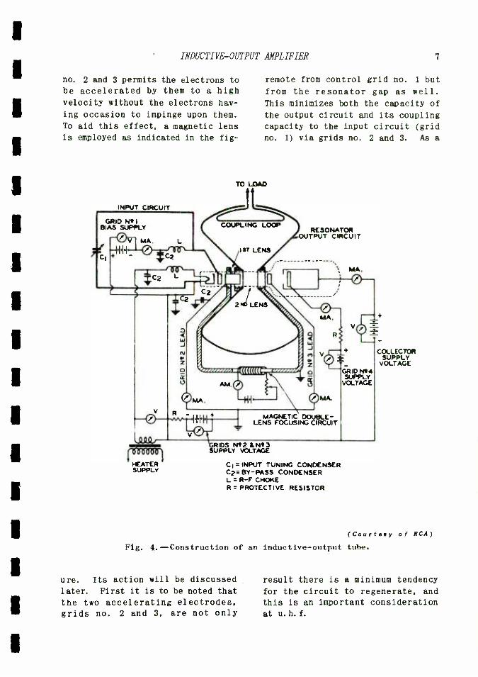
CONSTRUCTION OF INDUCTIVE -OUT- PUT TUBE.--In Fig. 4 is shown the inductive -output tube in conjunction
with a typical r -f amplifier cir- cuit. At the left of the tube envelope, shown in dotted lines, is
the heater and cathode of the tube.
Close to it and in front of it is
the control grid (grid no. 1). This
is spaced very close to the cathode,
as stated previously, and gives a
high ratio of transconductance to input capacitance, as well as short
transit time.
Two cylindrical electrodes, grids no. 2 and 3, are spaced in the
tube on either side of the gap in
the resonator. These electrodes are
operated at a high potential--nor- mally 3,600 volts. By using such a
high potential grid no. 2 can be spaced an appreciable distance from
control grid no. 1, and thus avoid additional capacity of the latter to
(a -c) ground, and yet produce an
appreciable electric field at the
cathode surface to draw a reasonably
large number of electrons through the tube. In addition, the high accelerating potential imparts a very
high velocity to the electrons as
they shoot past the gap.
In order to further prevent any
loss of velocity in the gap region,
the grid no. 3, also at 3, 600 volts potential, produces a region in the
tube between it and grid no. 2 that is at a constant potential, so that the electrons have no reason to lose
any velocity there. (There are no frictional forces to decelerate electrons in a vacuum.)
The cylindrical shape of grids
INDUCTIVE-OUTPUT AMPLIFIER 7
no. 2 and 3 permits the electrons to be accelerated by them to a high velocity without the electrons hav-
ing occasion to impinge upon them.
To aid this effect, a magnetic lens
is employed as indicated in the fig-
INPUT CIRCUIT
GRID Ni I
BIAS SUPPLY
remote from control grid no. 1 but
from the resonator gap as well.
This minimizes both the capacity of
the output circuit and its coupling
capacity to the input circuit (grid
no. 1) via grids no. 2 and 3. As a
TO LOAD
RESONATOR OUTPUT CIRCUIT
IsT LENS
2 P LENS
MA.
W J M M
V
'iuuuc: o
11 \
\ MA.
MAGNETIC DOUBLE E- LENS FOCUSING CIRCUIT
RIDS Ni2 &N*3 SUPPLY VOLTAGE
IMA.
COLLECTOR SUPPLY
T - VOLTAGE GRID N'4 VOLTAGE
CI = INPUT TUNING CONDENSER C2= BY-PASS CONDENSER L = R -F CHOKE R= PROTECTIVE RESISTOR
(Courtesy of RCA)
Fig. 4. -Construction of an inductive- output tube.
ure. Its action will be discussed
later. First it is to be noted that
the two accelerating electrodes, grids no. 2 and 3, are not only
result there is a minimum tendency
for the circuit to regenerate, and
this is an important consideration
at u. h. f.

8 SPECIAL ULTRA HIGH FREQUENCY TUBES
The cavity resonator is of the
reentrant type, with an appreciable gap length. This reduces the output
capacity and permits a higher imped-
ance for a given band -width. A
higher impedance across the gap means a higher induced voltage across the gap ends produced by the
variations in beam density. This is
an advantage as it permits a greater
fraction of the net beam voltage to
be converted in a -c voltage, but it
also tends to produce a certain amount of spreading or defocusing of
the electron beam.
Such de- focusing is objection-
able because it tends to make elec-
trons impinge upon the accelerating
electrodes, grids 2 and 3, which are
at a high potential. Electrons that impinge upon these electrodes repre-
sent a grid current and produce heating of the electrodes. This
is wasted energy that must come from
the power supply
To avoid such loss a system of
magnetic focusing is employed. A
suggested form is shown separate from the tube in Fig. 5. In es-
Non -magnetic
Material
Direction of
Magnetic Flux
1 Tield Coil
Fig. 5.--Magnetic-focusing system which can be used with an inductive -
output tube.
sence, three hollow iron members,
A. B, and C are held in line so that
the cavity resonator will fit be-
tween parts B and C, and the glass
tube will slip through the aligned holes in the three of them. They represent tnree magnetic poles in
series; the field coil forces flux through them as indicated.
If desired, one may regard the
right -hand face of A as a north pole, the left -hand face of B as a
south pole, its right -hand face as
another north pole, and the left -
hand face of C as the final south pole. The situation is analogous to
that of an electric circuit, where one point may be negative with re- spect to another point of the cir- cuit and positive with respect to a
third point of the circuit. Thus
part B is a south pole with respect
to A but is a north pole with re- spect to C.
The result is that magnetic fields are set up in the two air gaps, that between A and B and that
between B and C. The particular arrangement of Fig. 5 is merely for the purpose of attaining this result with one field coil. The magnetic fields form fringing lines into the tube, as indicated in Fig.
6. These constitute the first and
Electron
Fig. 6.--Effect of magnetic- focusing
in an inductive -output tube.

INDUCTIVE -OUTPUT AMPLIFIER
second lens of Fig. 4. Since an
electron in motion represents an
electric current, it will be acted
upon by the magnetic field in exact-
ly the same way as a current- carry-
ing conductor, such as the windings
of a motor armature. A force is set
up tending to move the electron in
a direction at right angles to its
original direction of motion and to
the direction of the magnetic field lines.
The result of all this is that .
electrons tending to diverge from the axis of the beam are twisted around by the magnetic field and
caused to converge toward the axis. This effect is made more pronounced
than the contrary diverging action
of the electric field lines at the
electrodes by passing sufficient current through the magnetic field
coil. At the same time such focus-
ing effects are required only at
two points, where the de- focusing is
most pronounced, as indicated by first lens and second lens in Fig.
4. Consequently only about 2 watts of d -c energy are required for the
magnet.
The above focusing action re-
duces the current to grids 2 and 3 to
a minimum: about 1.0 ma and 0.5 ma
respectively. The bulk of the beam
current proceeds to the collector,
Fig. 4, which is operated normally
at 1,500 volts. Since this is much
lower than the 3,600 volts of grids
2 or 3, it is clear that the elec- trons are decelerated between grid
no. 3 and the collector, and strike
the latter with less force. The normal collector current is about
45 ma, and the maximum collector dissipation is 50 watts maximum.
Consider a collector voltage of
1,500 and a collector current of 25 ma. (This is the case for a
9
Class C grid -modulated r -f power
amplifier.) The d -c power going into the tube is essentially 1,500
x .025 = 37.5 watts. The d -c power
going into the accelerating elec- trodes can be neglected, at most it
is 3 to 4 watts. The 37.5 watts d -c
input is in part converted into a -c
power output in the resonator. Suppose this amounts to 9 watts. Then the collector dissipation will
be 37.5 - 9 = 28.5 watts which is
well within the 50 watts maximum.
The beam current, in impinging
upon the collector which is at 1,500
volts potential, strikes it with
sufficient force to liberate low - velocity secondary electrons from it. These normally would be at- tracted to grid no. 3, which is
at a higher potential than the collector. To prevent this, a ring-
like electrode (grid no. 4) Fig. 4
is provided within the collector, and is operated at a potential of about 800 volts. It is thus rela-
tively negative with respect to the
collector, and repels any secondaries
generated within the collector to- ward the back of the latter, and thus prevents them from going to
grid no. 3. Any appreciable current
to grid no. 3 would represent a
large loss, since it is at a high potential (about 3,600 volts).
OPERATING FEATURES. - Some of the characteristics and operating features will be of interest. The
transconductance, for a plate cur- rent of 50 ma, is 5,500 µmhos. This
high value is due to the close spacing of the control grid to the
cathode. Yet the input capacitance
is only 3.2 µµf (control grid -to- cathode) plus 1.8 µµf (control grid -
to -grid no. 2).
Grid modulation is employed, since plate (collector) modulation
10 SPECIAL ULTRA HIGH FREQUENCY TUBES
would not appreciably affect the
Plate current because grids 2
and 3 act as a screen grid and
effectively shield the cathode from
the collector. Moreover, any variation in any of these volt-
ages would affect the beam velo- city and hence the speed with which
the clusters of electrons pass the resonator gap. From what has
been stated above it is clear that this would throw the rhythm of their passage through the gap
out of tune with the resonator.
Grids no. 1 and 2, as well as the heater, should be by- passed for r -f directly to the cath- ode. The r -f chokes shown in
Fig. 4 further aid to de- couple these electrodes from one an- other. The cathode and grids 1 and 2 are each connected with- in the tube to two terminals to
provide multiple contact, and it is recommended that both ter- minals to each electrode be em-
ployed in order to reduce lead inductance and resistance (the latter mainly skin effect).
All high voltage power sup-
plies should have good regula- tion. In placing the tube in
operation it is important that the sequency of operations be
as follows: 1). make certain that the magnetic circuit is func-
tioning, 2). make certain that the bias for grid no. 1 is con- nected and on, 3). apply heater collector, grid no. 4, grid no.
3 and then grid no. 2 voltages in order named, and 4). fin- ally apply the signal excita- tion.
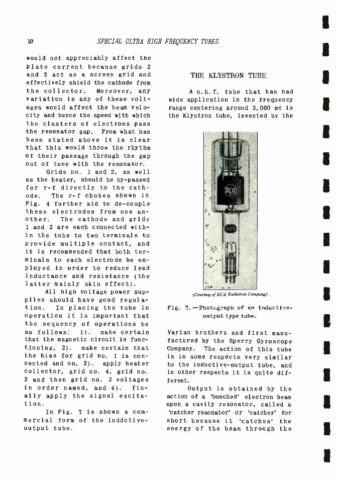
In Fig. 7 is shown a com-
mercial form of the inddctive- output tube.
THE KLYSTRON TUBE
A u. h. f. tube that has had wide application in the frequency
range centering around 3,000 me is
the Klystron tube, invented by the
(Courtesy of RCA Radiotron Company)
Fig. 7. -Photograph of an inductive - output type tube.
Varian brothers and first manu- factured by the Sperry Gyroscope Company. The action of this tube is in some respects very similar to the inductive -output tube, and in other respects it is quite dif-
ferent.
Output is obtained by the action of a `bunched' electron beam upon a cavity resonator, called a
'catcher resonator' or 'catcher' for
short because it 'catches' the energy of the beam through the
THE KLYSTRON TUBE 11
action of clumps of electrons passing
through it. In this respect it is
similar to the inductive -output tube, and the analysis given there
can be reread with profit in order
to understand the action of the
Klystron tube. The method of producing clumps
in the electron beam, or bunching'
as it is called, is different from
that of the inductive -output tube.
TUNING RING
There an ordinary negative control
grid, located close to the cathode,
was employed; in the Klystron bunch-
ing is produced by a ' buncher resona-
tor' or 'buncher,' for short, in
conjunction with a drift space.
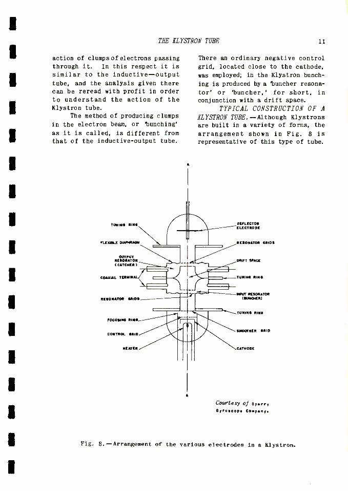
TYPICAL CONSTRUCTION OF A KLYSTRON TUBE.--Although Klystrons are built in a variety of forms, the
arrangement shown in Fig. 8 is
representative of this type of tube.
FLEXIGLE DIAPHRAGM
OUTPUT RESONATOR (CATCHER)
COAXIAL TERMIN i
RESONATOR GRIDS
FOCUSING RING
CONTROL GRID
HEATER
DEFLECTOR ELECTRODE
RESONATOR GRIDS
ORIFT SPACE
TUNING RING
INPUT RESONATOR (MUNCHER)
TUNING RING
SMOOTHER GRID
CATHODE
Courtesy of 9pry Dyrooop Company.
Fig. 8.--Arrangement of the various electrodes in a Klystron.
12 SPECIAL ULTRA
The electron gun or cathode assembly
furnishes a beam of electrons of essentially uniform velocity at
points along the axis beyond the electrode designated as the 'smooth-
er grid.' The 'buncher' and the
'catcher' are astride the axis at
a point beyond the 'smoother grid.'
They are two reentrant cavity resonators with their reentrant (buckled -in) sides facing one another, and mechanically form one unit, although electrically they are distinct from one another.
One can regard each as of the form shown in cross - section in
Fig. 9, namely, as a cylinder with
Grids - Reentrant
Portion
Fig. 9. -Cross -section view of bunch - er and catcher.
one face depressed so as to be
close to the other face and thus form a depressed cylinder or reen- trant portion within the main cylinder. Such a cavity resonator approaches a lumped circuit in behavior in that the portion marked grids has the greatest concentra- tion of electric field lines, and
hence acts essentially as the capacitor of the resonant combina- tion, while the surrounding volume contains the bulk of the magnetic field lines and acts principally as the inductance. This has also been discussed in the assignment on cavity resonators.
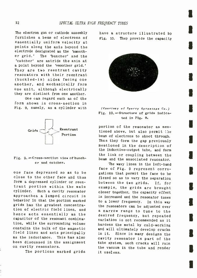
The portions marked grids
HIGH FREQUENCY TUBES
have a structure illustrated by Fig. 10. They provide the capacity
(Courtesy of Sperry Gyroscope Co.)
Fig. 10.--Structure of grids indica-
ted in Fig. 9.
portion of the resonator as men- tioned above, but also permit he beam of electrons to shoot through. Thus they form the gap previously mentioned in the description of the inductive -output tube, and form
the link or coupling between the beam and the associated resonator.
The wavy lines in the left -hand face of Fig. 9 represent corru- gations that permit the face to be
flexed so as to vary the separation between the two grids. If, for example, the grids are brought closer together, the capacity effect is increased and the resonator tunes to a lower frequency. In this way the resonators can be adjusted over a narrow range to tune to the desired frequency, but repeated variation is not recommended as it
hardens the metal by cold- working and will ultimately develop cracks in it. Since in many designs the cavity resonator is part of the tube system, such cracks will ruin the vacuum in the tube and render it useless.

THE KLYSTRON TUBE 13
The space between the two reentrant portions of the two resonators forms the drift space. This is the region where the elec- trons sort themselves out into clumps or bunches before passing through the gap of the 'catcher,' where output energy is obtained from the beam. Finally the elec- tron beam is either collected by a
positive electrode beyond the catch- er, or else deflected by a de- flector electrode either at cathode potential or negative to the cathode onto the side walls of the tube.
Input and output power is fed to the buncher and catcher respec- tively by means of coaxial lines that screw on the coaxial terminals. The latter have glass seals in the case where the resonators are part of the vacuum system. Magnetic (loop) coupling is employed, as
indicated in .Fig. 11 because such coupling is more practical than electric field coupling to the grids, where the electric field is at a maximum. (Coupling loops have been discussed in a previous assign-
ment.)
FUNDAMENTAL ACTION OF THE KL YSTRON TUBE. -The manner in which a uniform stream of electrons is
converted into a non -uniform stream having dense or rarefied portions is different in a Klystron tube from the gate or valve action in an
ordinary triode or even the induc- tive- output tube. The action can be
explained as follows: suppose a
uniform beam of electrons at some constant high velocity shoots through the gap in the launcher', as
indicated by Fig. 11, and that the ' buncher' is excited, such as
by means of a loop, at its resonant
frequency.
At some instant gap -side B is
positive relative to gap -side A,
although, as shown, A is neverthe-
To U.H.F.
Source
Electron -
Beam
-1111110 4-
A
Eac
Fig. 11.--Electron beam in transit through the buncher.
less positive with respect to the
cathode. Let the voltage between A and B be E.e. The velocity of all the electrons passing through A is
assumed to be the same and is due to the voltage Ede. To this voltage must be added E across the gap to obtain the voltage at gap - side B.
The electrons are thus at the moment under consideration being further accelerated through the gap
so that they emerge with a higher velocity at side B than they had at side A. It can thus be expected that they will tend to catch up with
electrons that passed through AB at a moment when Esc was passing through its zero value, since these
earlier electrons were not acceler- ated while passing through the gap and therefore had no higher velocity at B than they had at A.
But in the short distance AB
14 SPECIAL ULTRA
and in the short time required by
the high -speed beam to traverse AB
the later faster -moving electrons
have not been able to overtake the
earlier slower- moving electrons; such an overtaking or catching -up
process occurs farther on to the
right in Fig. 11.
As a result, if say, n elec-
trons per second enter A at velocity
v1, then exactly the same number of electrons per second will leave B a
moment later, but their velocity will be v2 owing to the additional acceleration of Vag. In short, if
the beam has uniform density at
A (the same number of electrons Passing through the beam cross - section in one moment as during the next,) then the beam will have
a uniform density at B; all that
will be noticed at B is that the
electrons pass through B at a
uniform rate but with a higher velocity than at A.
If one were to stand at A and
observe electrons, one would count
exactly the same number passing through every second, or microsecond,
and all electrons would have sub-
stantially the same velocity owing
to Ede. If one were to stand at B,
one would again count as many elec-
trons passing by B in one second as
the next, but here, owing to Ede,
the velocity with which the elec-
trons emerged would vary in an
alternating manner with time, even
though as many electrons passed by B at one moment as the next. One
says that the density of electrons
at B is constant, but that the velo-
city of the electrons passing through B is modulated.
Suppose now the electrons are
permitted to flow through a space
across which there is no difference
of potential, so that no forces of
HIGH FREQUENCY TUBES
acceleration or deceleration acts
upon them. This is known as a
'drift space,' and exists between the two reentrant resonators in
Fig. 8. In such a region electrons
of higher velocity have more dis- tance, hence time, to catch up with slower- moving electrons, and elec-
trons that have been actually decel-
erated by Eao during its negative half -cycle have time further to lag
behind those of average velocity and thus produce regions in the beam
where the electron density is very low. Thus, at the end of the drift space the electrons will emerge in
clumps or bunches, and will be able
to affect the 'catcher' resonator.
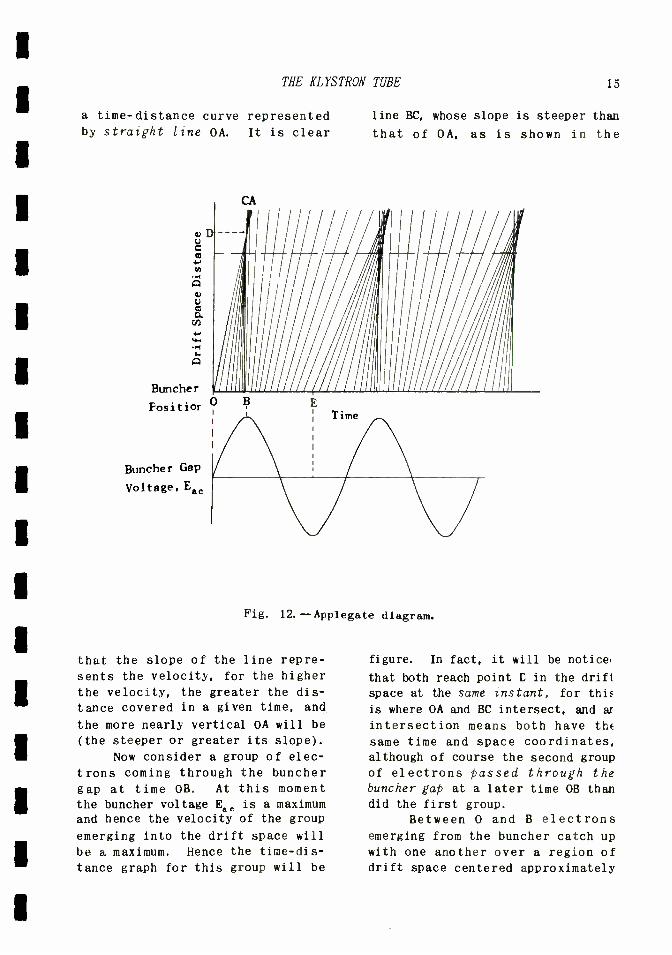
There is a diagram known as
the Applegate diagram that enables these matters to be represented graphically. Suppose, as in Fig.
12, time is plotted as the abscissa and distance traversed by an elec- tron as the ordinate. Let the dis- tance be measured from the center of the gap in the buncher (denoted by
Puncher Position') and let time be
measured from a moment when Ea, de- veloped across the buncher gap is
passing through zero in a positive direction.
Although it is assumed that electrons are coming through the buncher in a continuous stream, one can approximate this condition by assuming that groups of electrons come through at equally spaced time intervals. While this means that the beam is made up of clumps of electrons, these can be chosen so closely spaced as to approximate absolutely uniform conditions.
Thus, consider a group of elec- trons coming through at time t = O.
As time increases, these electrons pass through succeeding portions of the drift space, and give rise to
THE KLYSTRON TUBE 15
a time - distance curve represented by straight line OA. It is clear
line BC, whose slope is steeper than
that of OA, as is shown in the
Buncher
Fositior
Buncher Gap
Voltage, Eac
Fig. 12.--Applegate diagram.
that the slope of the line repre-
sents the velocity, for the higher
the velocity, the greater the dis-
tance covered in a given time, and
the more nearly vertical OA will be
(the steeper or greater its slope).
Now consider a group of elec-
trons coming through the buncher gap at time OB. At this moment the buncher voltage Eac is a maximum and hence the velocity of the group
emerging into the drift space will
be a maximum. Hence the time -dis-
tance graph for this group will be
figure. In fact, it will be notices
that both reach point D in the drift
space at the same instant, for this
is where OA and BC intersect, and ar
intersection means both have the
same time and space coordinates, although of course the second group of electrons passed through the
buncher gap at a later time OB than did the first group.
Between 0 and B electrons emerging from the buncher catch up with one another over a region of drift space centered approximately
16 SPECIAL ULTRA HIGH FREQUENCY TUBES
at the broken line shown in Fig. 12.
In other words, the faster- moving electrons do not catch up with the slower -moving electrons at one point in the drift space, but rather over a small region. At one cross -sec- tion of this region the density is a maximum, but ahead of this cross - section the electrons are beginning to 'bunch', and following it they have not as yet 'debunched.'
Electrons that leave during the
time interval BE are being more and more decelerated, since the buncher voltage E8C is changing during this time from its maximum positive to
its maximum negative value. Hence,
later electrons emerge from the buncher gap with a lower velocity than those preceding them, and lag more and more behind their pre- decessors as they continue through the drift space. At the distance represented by the broken line they
are quite far apart and represent a
rarefaction in the electron beam.
Thus a succession of dense and
rarefied portions of the electron beam pass by at a certain cross - section of the drift space in time sequency, and the velocity modula- `ion of the beam at the beginning of
the drift space has been converted into a density modulation at the Joint in the drift space mentioned above, and denoted by the broken Line in Fig. 12. If the catcher'
gap is located at this point, the beam will be able to drive it and
furnish it with power, which can then be extracted from the 'catcher'
by a coupling loop, for example.
Since the potential developed
across the 'catcher' gap is of such
phase that it tends to decelerate the dense portions of the beam and
accelerate only the rarefied por- tions--as has been explained in the
case of the inductive -output tube--
it is clear that on the average most
of the electrons are decelerated by the 'catcher' voltage from the average velocity that the d -c beam
voltage has imparted to them. Hence
the energy extracted by the 'catcher'
comes from the d -c beam voltage source, and not from the "buncher" signal source. This is important, because it indicates that u. h. f.
output energy can be obtained from the d -c input energy just as in the case of the conventional tube, and this output energy can be many times that coming into the 'buncher'. Thus amplification of u. h. f. energy is possible.
The energy extracted from the buncher' by the electron beam under-
going velocity modulation is nor- mally very small. This is because the buncher' gap is so short that the electrons pass through in very little time. Hence, even though they are accelerated or decelerated during this small time to higher or lower velocities at the output of the buncher than they had at the input, they nevertheless have not had sufficient time to sort them- selves out into clumps. Therefore the electron density in transit through the buncher gap is essen- tially uniform. Such a uniform beam does not induce currents in the buncher', i. e. , does not cause the buncher to draw appreciable in- phase current from the signal source and so does not load it.
Another way to state this is to say that the buncher gap accelerates as many electrons during the positive half -cycle of the signal voltage as it decelerates during the negative half -cycle. It therefore receives back from the beam during the decelerating half -cycle as much
THE KLYSTRON TUBE 17
energy as it gave into the beam during the accelerating half -cycle;
the average energy over a cycle is
zero, and thus the gap does not load the signal source.
This is important: the prin- cipal objection to the ordinary negative grid tube is the loading on its input circuit by transit -time effects. This is due to the fact that the grid varies the density of the electron flow even in the space between it and the cathode. In the
Klystron this is avoided by making the beam current or rather density unaffected by the signal voltage in
the small region where the signal voltage is applied (buncher gap), but then employing transit time effects in the drift space to allow the velocity modulation imparted at the buncher gap to be converted by a sorting process into a density modulation at the catcher gap. The density modulation can then affect the catcher and give up beam energy to it.
KLYSTRON AMPLIFIER. -The above discussion indicates that Klystron can act as an amplifier, and furnish more output energy at signal fre- quency than is extracted from the signal source by the input buncher of the tube. As an indication of the low input loading possible in
the tube, an effective grid impedance as high as 50, 000 ohms at 5,000 me is
possible in the Klystron. Compare this with 1100 ohms at 400 me for a
955 acorn tube.
Several important factors must be noted in the operation of the Klystron as an amplifier. In the first place, it has been assumed that the buncher gap signal voltage Ear is small compared to the d -c beam accelerating voltage Ede. Thus the variation in velocity with time
of the electrons emerging from the
buncher gap is small compared to the
average of constant velocity com- ponent due to Edo, and the varia- tions may be regarded as being sinusoidal when platted against time. For a given peak amplitude of this sinusoidal variation, maximum bunch- ing occurs at a certain place in the
drift space.
Beyond this place the faster - moving electrons begin to leave be- hind the slower -moving electrons they just overtook, and a distorted double -peaked density distribution, with a rarefaction between the peaks, occurs in the beam at a
certain distance beyond where a clump of electrons were formed. It will be appreciated that the action becomes more confLsed and jumbled as one proceeds along the drift space, i.e., the electron 'traffic jams' and 'open spaces' become less pronounced. A mathema- tical analysis indicates that the a -c catcher or output current, for fixed buncher signal and d -c ac- celeration voltages, varies with the position of the catcher (length of drift space between catcher and buncher) as indicated in Fig. 13. Thus, for a certain drift distance (labelled 1.84) the catcher current is at a maximum; bunching is at a maximum there. At about 3.8 units the beam has become uniform again, and a catcher gap located at this distance would not be energized by the beam.
The following negative maximum indicates a distance at which the bunched and rarefied parts of the beam have interchanged their rela- tive positions or timing with a
corresponding 180° phase shift. It will be noted from Fig. 13 that the successive maxima are of smaller
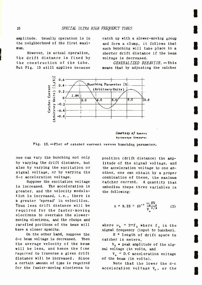
18 SPECIAL ULTRA
amplitude. Usually operation is in
the neighborhood of the first maxi-
mum.
However, in actual operation,
the drift distance is fixed by
the construction of the tube. But Fig. 13 still applies because
e.
C
A F.
0.6
0.4
0.2
o
-0.2
-0.4
-0.6
HIGH FREQUENCY TUBES
catch up with a slower- moving group
and form a clump, it follows that
such bunching will take place in a
shorter drift distance if the beam
voltage is decreased.
GENERALIZED BEHAVIOR. -This means that by adjusting the catcher
A, T 1
:unching Parameter [X]
(Arbitrary Units )_ I
Am- EOM EPA 2.0 .0 F_ 8.0
NM
Fig. 13. -Plot of catcher current
one can vary the bunching not only
by varying the drift distance, but
also by varying the excitation or signal voltage, or by varying the d -c acceleration voltage.
Suppose the excitation voltage
is increased. The acceleration is
greater, and the velocity modula- tion is increased, i.e., there is
a greater 'spread' in velocities. Thus less drift distance will be
required for the faster -moving electrons to overtake the slower - moving electrons, and the clumps and
rarefied portions of the beam will
have a closer spacing.
On the other hand, suppose the
d -c beam voltage is decreased. Then
the average velocity of the beam will be less, and hence the time
required to traverse a given drift
distance will be increased. Since
a certain amount of time is required
for the faster -moving electrons to
0.0
Courtesy of Sprry Gyroscope Copny.
versus bunching parameter.
position (drift distance) the amp-
litude of the signal voltage, and
the acceleration voltage to one an-
other, one can obtain by a proper combination of these, the maximum catcher current. A quantity that embodies these three variables is
the following:
w SV x = 8.33 x 10-' (2)
o
where wl = 27f1 where fl is the signal frequency (input to buncher).
S = length of drift space to catcher in meters,
V1 = peak amplitude of the sig- nal voltage (in volts, and
Vo = D.0 acceleration voltage of the beam (in volts).
Note that the lower the d -c
acceleration voltage Vo, or the
t
i
THE KLYSTRON TUBE 19
greater the peak a -c voltage V1,
the smaller must the drift distance
S be to the point where bunching occurs. Also, the higher the fre-
quency, the more rapidly will V1
vary from a positive to a negative peak, and vice versa, and hence the shorter must the drift distance be.
Thus x combines these factors into a single variable, in terms of which the variation of catcher cur- rent can be expressed as a Bessel
function J1 (x), whose plot is given
in Fig. 13. Thus if S, W1, and Vo
are kept constant, Fig. 13 shows how the catcher current varies as
the signal input is varied; if S,
Vo, and V1 are kept constant, the figure shows how the catcher current
will vary with the frequency of excitation al.. and so on.
Thus the variable x is a sort
of generalized quantity that enables the behavior of different Klystron tubes to be represented by the sin- gle curve of Fig. 13, and furnishes
the key to the practical performance of this type of tube.
KLYSTRON TUBE PERFORMANCE. --One thing that results from the above
relations is that for a fixed drift distance S, as is normally the case,
the accelerating beam voltage Va
should be reduced if the input sig-
na]. voltage V1 is small in order to
obtain maximum catcher current and
hence output. If, however, very weak signals are to be amplified, so
low a beam voltage may be necessary
that the beam will not be able to be
focused. Hence for weak signal operation, the point will be below
the first maximum of Fig. 13, where
x = 1.84.
Another factor that enters into
low level amplification is the sig-
nal-to-noise ratio. The induced noise in a Klystron is higher than
that in an ordinary tube, and miti-
gates against its use for such pur-
poses. The question of noise will be
discussed more fully later on.
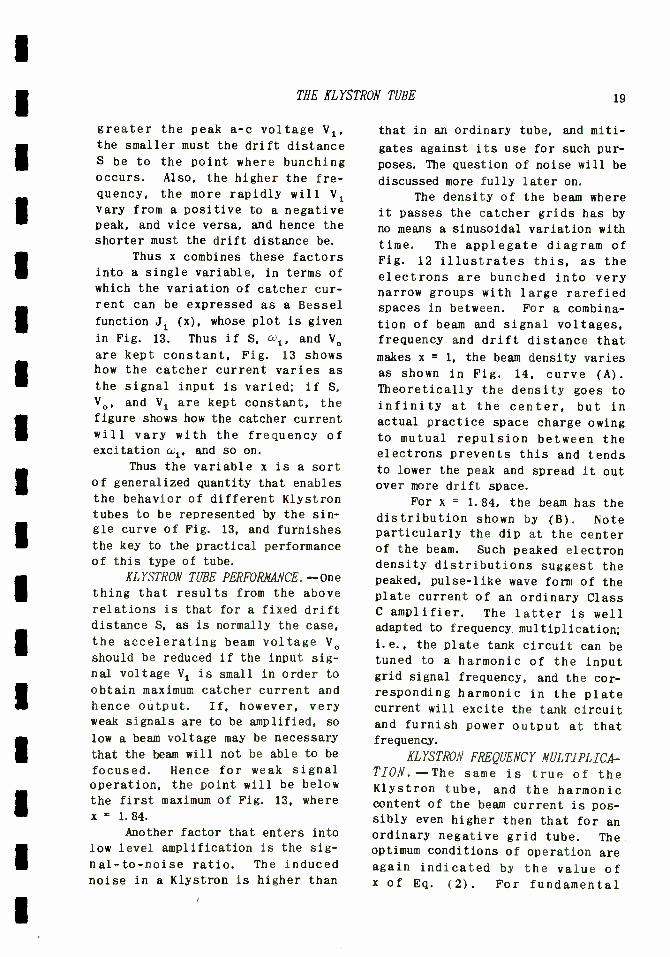
The density of the beam where
it passes the catcher grids has by
no means a sinusoidal variation with
time. The applegate diagram of Fig. 12 illustrates this, as the
electrons are bunched into very narrow groups with large rarefied spaces in between. For a combina-
tion of beam and signal voltages, frequency and drift distance that
makes x = 1, the beam density varies
as shown in Fig. 14, curve (A).
Theoretically the density goes to infinity at the center, but in
actual practice space charge owing to mutual repulsion between the electrons prevents this and tends to lower the peak and spread it out over more drift space.
For x = 1.84, the beam has the distribution shown by (B). Note particularly the dip at the center of the beam. Such peaked electron density distributions suggest the peaked, pulse -like wave form of the plate current of an ordinary Class C amplifier. The latter is well adapted to frequency. multiplication;
i.e., the plate tank circuit can be tuned to a harmonic of the input grid signal frequency, and the cor- responding harmonic in the plate current will excite the tank circuit and furnish power output at that frequency.
XLYSTRON FREQUENCY MULTIPLICA- TION.--The same is true of the Klystron tube, and the harmonic content of the beam current is pos- sibly even higher then that for an ordinary negative grid tube. The optimum conditions of operation are again indicated by the value of x of Eq. (2). For fundamental
20 SPECIAL ULTRA HIGH FREQUENCY TUBES
operation, the catcher is tuned to
the same frequency as the buncher, and the optimum value of x is 1.84. For third harmonic operation the catcher is tuned to three times the
buncher or signal frequency, and the
optimum value of x is 1.4.
engineering, and represent the sum
of an infinite series of terms, each of which involves the variable
in question, here x. Actually a
Bessel function is no more complica-
ted than a sine function. While a
geometrical representation of a
d
(B)
Optimum Bunching Bunching Para-
meter, X = 1.84
Average Current 1 U
(A)
Ideal Bunching Bunching Para - meter, x= 1.00
wt = -n 0 w t = -1-Tt
Courtesy of Sperry Gyroeop Company.
Fig. 14.--Beam density for various bunching parameters.
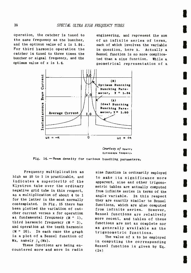
Frequency multiplication as
high as 10 to 1 is practicable, and indicates a superiority of the Klystron tube over the ordinary negative grid tube in this respect, as a multiplication of about 4 to 1
for the latter is the most normally contemplated. In Fig. 15 there has been plotted the variation of cat- cher current versus x for operation at fundamental frequency (M = 1),
third harmonic frequency (M = 3),
and operation at the tenth harmonic
(M = 10). In each case the graph is a plot of a Bessel function of Mx, namely j i (Mx).
These functions are being en- countered more and more in radio
sine function is ordinarily employed
to make its significance more apparent, sine and other trigono- metric tables are actually computed from infinite series in terms of the angle variable. In this respect they are exactly similar to Bessel functions, which are also computed from infinite series. However, Bessel functions are relatively more recent, and tables of these functions are not as complete nor as generally available as the trigonometric functions.
The value of x to be employed in computing the corresponding Bessel function is given by Eq. (2a)
i
THE KLYSTRON TUBE 21
a) SV x = 8.33 x 10⁻⁷
2 1
MVo 3/2
where all similar quantities have the same signigicance as in Eq. (2)
and in addition, a2 is the angular frequency of the catcher resonator, and M is the multiplication factor or order of the harmonic.
From a practical viewpoint, Fig. 15 indicates that operation as
a multiplier requires a lower value
of x as the value of M is increased. Thus the beam density curve varies from (B) of Fig. 14 for fundamental
operation toward (A) as the value of M is decreased.
As an example of the above,
suppose a Klystron is to be operated at 3,000 mc (catcher output), and the tenth harmonic is to be employed
(M = 10). Then the buncher signal frequency will be 3,000 : 10 = 300
mc. Let the drift distance be 3 cm = .03 m, and the d -c accelera- ting voltage be 1,000 volts. It is
required to find the peak r -f buncher voltage V1.
Eq. (3) can be solved for V1
by ordinary algebraic transposition.
For M = 10, Fig. 15 indicates that the optimum value of x is 1.2. Then
V1 = xMV32
8.33x 10 -7co2S
1.2 x 10 X (1000)3/2
8.33 x 10-7 x 27 x 3 x 109 x .03
800 volts.
This is a very high buncher volt-
age-- nearly equal to the beam volt-
age of 1,000 volts. It is question-
able whether the simple theory
applies in such a case. The reason
is that the optimum value of x has been used for M = 10, and the drift
space S has been relatively short for such a purpose.
On the other hand, if funda- mental operation were desired, the
optimum value of x would be higher, 1.84, but M would equal unity in- stead of 10, and the buncher driving voltage would be
V1 =
1.84(1000)3/2
8.33 x 10-7 x 27 X 3 X 109 X .03
122.5 volts
which is considerably less. Note that V1 is the voltage at the buncher grids. The voltage in the coupling loop of the buncher reso- nator is far less. The method of calculating this, for matched con- ditions has been given in a previous assignment on wave guides, in terms of the Q of the resonator. For a
Klystron the Q is in the neighbor- hood of 3, 500.
in spite of the high value of excitation voltage calculated above, usuable outputs at a ten- fold multiplication of frequency are obtainable from a Klystron. This is particularly important where it is desired to control the output frequency by means of a low -fre- quency crystal oscillator. For example, a 2.083 mc crystal oscil- lator, followed by a frequency tripler, would yield 6.25 mc one quadrupler would raise this to 4 x 6.25 = 25 mc, another quadrupler would yield 100 mc, and a tripler

22 SPECIAL ULTRA HIGH FREQUENCY TUBES
would then furnish 300 mc. These tubes could all be of the negative - grid type. Then a Klystron would
0.6
: 0.4 u.. á 0.2
0 w m
-0.2 w A u 6-,
X 6 -0.4
-0.6
resonators must be employed at low
frequencies. For these reasons, Klystrons are not employed be-
M=1
"1.26 16 11111M M=10
Bunchin Par ame terx]
1.0 1.40 2.0
Courtesy of Sperry Gyroscope company.
Fig. 15.--Variation of catcher current with bunching parameter.
multiply this frequency ten -fold to
yield 3,000 mc, which could then be
employed to operate a parabola or horn to furnish a blind -landing beam. This is purely an example;
blind -landing systems are covered
quite thoroughly in the Aeronautical
Radio Engineering Section.
FREQUENCY ADAPTABILITY. -From Eq. (2), repeated below
G;
2
SV x = 8.33 x 10⁻⁷ Va/s
o
(2)
it follows that if the frequency,
hence £1, is very low, then, for optimum fundamental operation for
which x = 1.84, either V1 must be of
an impractically high value, or V.
must be of an impractically low value (as regards focusing ability
of the electron beam), or else the
drift space S must be unduly long.
In addition, very large cavity
low about 3,000 mc.
The fact that the resonators are in many designs integral por- tions of the tube indicates that the tube is not well adapted to
tuning over a wide range of fre-
quencies, but rather is better suited for single frequency opera- tion. This is removable and can be replaced by one tuned to an- other frequency.
DEBUNCHING. -Brief mention has been made that the bunched parts of the beam do not have infinite density, as indicated by
theory, because of mutual repul- sion between the electrons consti- tuting the beam. Such space charge
effects tend in general to de- bunch the beam longitudinally as well as make it spread apart. While the latter action can be minimized by magnetic focusing, as in the inductive -output tube, such complication is in general
1

THE KLYSTRON TUBE 2 3
undesirable.
The debunching effect is more pronounced if the drift dis- tance S is large. This is unfortu-
nate, since Eq. (2) indicates that if S is increased at a given frequency and beam voltage, V1- the signal voltage--can be decreased for a given output voltage. In
short, if S could be increased, the voltage gain could be in- creased. But, owing to the de-
bunching effect, as well as high noise level, high -gain low level voltage amplifiers are not parti- cularly successful.
Another application affected by
debunching is that of high power tubes, wherein the beam current is
large. It is for this reason that
Klystron tubes are not adapted to pulse operation, in which momentary
high power output pulses are devel-
oped. Fortunately other tubes are
available.
SIGNAL -TO -NOISE CONSIDERA- TIONS. -The electron beam originates at the cathode, and the emission of
electrons from the cathode is ran-
dom. As a result the density of the
electrons in the beam varies from point to point, and with time, in a
random manner characteristic of
noise. As these `noise clumps' of
electrons pass the buncher gap,
Fig. 16, they induce a mean - squared
noise current in2 in the gap.
The actual arrangement can be replaced by an equivalent lumped circuit as shown in the right -hand
figure. The cavity resonator is represented by L, C, and Rs, where
R represents the losses in the resonator as an equivalent shunt resistance. The antenna is repre-
sented by a source ea having an in-
ternal resistance Ra. The coupling
loop in the actual buncher cor- responds to a step -up transformer action of l:m, as shown. Hence R.
appears as m2Ra in parallel with R .
g Normally the resonator losses
are very small, so that Rs is corre-
spondingly very large, and may be
ignored in comparison with m2Ra shunting it. The noise current in2 can be expressed in terms of the
beam current Ib and the band width of operation 4f. Thus
1n2 = 2eIbAf
where e is the electron charge. This induces a mean - square noise voltage across the buncher gap of in2 02D %2. which then velocity - modulates the beam and produces noise at the output. This source of
noise may exceed other sources, and
is a serious limitation to the use
of the Klystron in amplifying low - level signals, such as from an
antenna.
In addition to this noise, noise is developed at the catcher and beyond. As was shown pre- viously, these can be represented by
an equivalent noise resistance R.
located at the buncher grid. This
generates the mean -square noise voltage en2
= 4kTrRegAf, as indicated
in Fig. 16.
As the transformer ratio m is
increased (tap moved down), the signal voltage ea is stepped up to a
higher value me., but R is also stepped up to a higher value m2Ra,
and enables i to develop a higher
noise voltage. Hence an optimum value of m is reached for which the signal /noise ratio is a maximum

24 SPECIAL ULTRA HIGH FREQUENCY TUBES
This is
(S /N) 2 (max.) _
(4wrrR Af 2 20RR q
e2 A
1
(3)
As a numerical example, suppose the antenna generated voltage ea is
C athode
/Electron Electron
I Gun
Fig.
unche
Gap
1 Electron f --I-- - -
Beam
To
Antenna
left -hand peak is repeated in Fig. 17. Suppose in the operation of the tube the signal voltage is so high that x = 2. 5. In this case decreasing the signal voltage until x = 1.84 will actually increase the catcher output. Further decrease will then decrease the catcher out- put.
Operation for x greater than
é -= 4kTRR qA f
Buncher
Resonator
16.--Illustration of electron beam passing through buncher gap and equi- valent lumped circuit thereof.
20 µvolts, Tr = 300 °K, RA = 75 ohms, Af = 5 mc, ID = 25 ma, and Reg = 200 ohms. Then
1.84 is termed 'over-bunching'. It can be detected by varying the buncher voltage. The simplest way
(S/N)2(max.) = (20 x 10-6)2 4 x 1.37 x 10-23 x 300 x 75 x 5 x 106
1
2 /20 x 25 x 10'3 x 200
OVER -BUNCHING AND UNDER BUNCH-
ING. -It was stated that an optimum value of x for the fundamental mode of operation is 1.84. This was illustrated bs Fig. 13. The first
3. 25
to do this is to detune the buncher resonator. This decreases the signal voltage developed across the buncher grids, and thus enables x to be varied through its optimum value

THE KLYSTRON TUBE 25
with resultant maximum output. Since detuning can be accomplished on either side of resonance, two
0.6
0.4
0.2
-0.2
-0.4
-0.6 Courtesy of 6y ******o Company
Fig. 17. -- Catcher current versus bunching parameter.
maximum values of the catcher output are obtained as one tunes through resonance.
Under - bunching occurs when x is
less than its optimum value of 1.84,
and is more difficult to detect. However, if the beam voltage is reduced, x can be increased until over- bunching occurs, and the double maxima can be observed. The ac- celerating voltage can then be in-
creased until optimum bunching occurs (x = 1.84). By means of the
above tests either the signal voltage or the accelerating voltage can be
adjusted to obtain maximum output. KLYSTRON OSCILLATORS.- If some
of the catcher output is fed back to
the buncher, as, for example, by means of coaxial cable, oscillations can occur. Thus the Klystron can function as an oscillator, and this
is one of its most important func- tions, since an oscillator permits u. h. f. energy to be generated, and also permits received energy to be
detected by means of immediate
conversion to an intermediate fre- quency if r -f amplifiers of adequate
gain and signal /noise ratio are not
avail able.
Unlike negative -grid tube oscillators, Klystron tubes will not
oscillate unless all conditions are just right. This includes the mag- nitude of the accelerating voltage. The reason will be apparent from the
block diagram of Fig. 18. This rep-
resents any feed -back type of oscil-
lator.
Input
Feedback Path ß /eß
E
81
Forward Path
Output
Fig. 18. -Block diagram of feed -back type of oscillator.
Suppose a voltage E1 is im-
pressed across the input terminals* of an amplifier. Let the amplifier have a gain of aL1. The signifi- cance of this statement is that E1 is amplified to the value aE1 = E2 in magnitude, and further that the output voltage E2 lags E1 by the angle 61, which represents the phase shift in the amplified system or forward path. Usually e1 is due to
plate load reactances, but at u. h. f. ,
*Strictly speaking, the input terminals of an oscillating system are in many cases not well- defined. However, the input may be taken at any point in the system, such as the grid circuit of a single -tube oscillating system.
26 SPECIAL ULTRA HIGH FREQUENCY TUBES
transit -time angles in negative - grid tubes, and drift transit -time in Klystrons, can cause the phase angle 01. For example, a might be 10 01 = 40°.
In order to oscillate, some of
the output voltage is fed back via the feedback path. This may be a
lumped network or a transmission line. It returns to the input terminals a voltage equal to ßE2 in
magnitude and shifted in phase from
E2 by the angle 02. For example,
ß might be .2, and 02= 220 °. In
ordinary oscillator action this voltage is identical with E1, that is, the voltage fed back is the input voltage. Hence one can write
and
aE1a = E2
EaL2 = E1
These two equations can be solved simultaneously to obtain the values of aß and of 01 + 02. Thus multiply
the second equation by the complex number denoted by aLQ1, meaning the magnitude a at the angle 01: to multiply two complex numbers. Hence there is obtained
aßE2622 + 01 = aE /01
But from the first equation. aE1L1 equals E2.
ca2Le2 + 1 = E2
Divide through by E2 and obtain
aßL02 ± di 1 (4)
This states that the complex quan- tity whose magnitude is aß and which
represents the gain around the feed -back loop, and whose angle is
(02 + 01), which is the phase shift
around the feed -back loop, must equal the real number unity. This
can be so only if the magnitude aß is unity, and the angle (02 + 01) is
0, or 360° (27r radians), or a mul-
tiple thereof. Thus the conditions
for sustained oscillations in a
feed -back system are those given by Eq. (4) or by the equivalent two
equations below, namely,
a ß = 1
(5)
(02 + 01) = 2nnr
where n is an integer of value 0,
1,2,3, etc.
In practice the latter condi- tion is the more important. It
states that the voltage fed back is
in phase with the initial voltage that started the oscillation, i.e.,
regenerative feedback. Ordinarily the integer n has the value of 1,
or possibly 2, 3, etc. , and rarely the value of zero. In general 01 and e
2 are functions of frequency
and so the frequency of oscillation is that which makes (02 + 01) = 2mr.
For high Q output tank circuits the above frequency is very closely that which the tank circuit is resonant.
The requirement that aß= 1 is
normally met by the oscillating system in the following manner: the
amplitude of oscillations increases to a point where the tube overloads. This decreases the forward gain a until aß = 1. Thus the latter requirement normally fixes the amplitude of oscillation, while (01 + 02) = 2mr normally determines the frequency of oscillation.
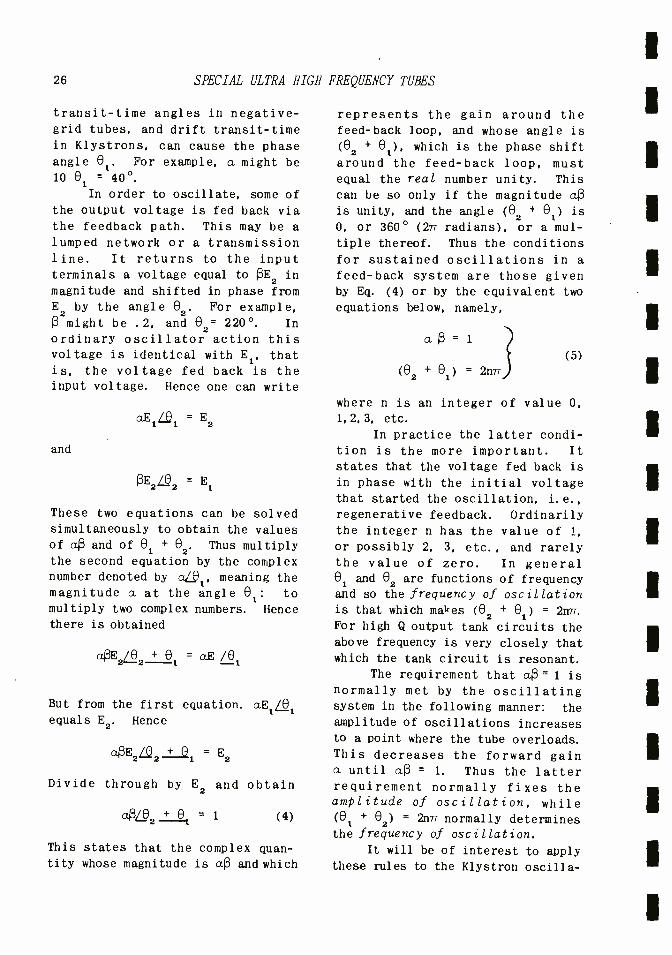
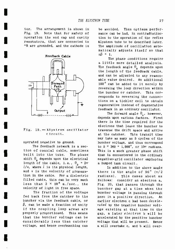
It will be of interest to apply these rules to the Klystron oscilla-
THE KLYSTRON TUBE 27
tor. The arrangement is shown in
Fig. 19. Note that for safety of operation the end cap and cavity resonators, that are connected to
+B are grounded, and the cathode is
Feedback Cable
Fig.
r Output
19. - Klystron oscillator c iren it.
operated negative to ground. The feedback network is a sec-
tion of coaxial cable, sometimes built into the tube. The phase shift e2 depends upon the electrical
length of the cable, i. e. , 02 = 2ri l /v, where l is its physical length,
and v is the velocity of propaga- tion in the cable. For a dielectric filled cable, this can be very much
less than 3 x 10⁸ m. /sec., the velocity of light in free space.
The fraction of the voltage fed back from the catcher to the buncher via the feedback cable, or
ß, can be made a fraction of unity
if the coupling loop areas are properly proportioned. This means that the buncher voltage can be considerably less than catcher voltage, and hence overbunching can
be avoided. Thus optimum perfor- mance can be had, in contradistinc-
tion to the operation of the reflex
Klystron tube to be described later.
The amplitude of oscillation auto- matically adjusts itself so that aß = 1.
The phase conditions require a little more detailed analysis. The feedback angle 02 depends upon the length of the feedback cable,
and can be adjusted to any reason-
able value desired. An additional
180° can be added to it merely by
reversing the loop direction within
the buncher or catcher. This cor-
responds to reversing the connec- tions on a tickler coil to obtain regenerative instead of degenerative
feedback in an ordinary oscillator.
The forward angle 01, however,
depends upon various factors. First
there is the time required for the electrons that leave the buncher to
traverse the drift space and arrive
at the catcher. This transit time may take as many as 5 cycles of the
buncher voltage, and thus correspond
to 5 x 360 = 1, 800 °, or 107 radians.
This is a much greater phase shift than is encountered in the ordinary negative -grid oscillator employing a lumped tank circuit.
In addition to the above angle there is the angle of 9G° (7/2 radians). This comes about as
follows: consider an electron a,
Fig. 20, that passes through the buncher gap at a time when the buncher voltage is passing through zero in a positive direction. An
earlier electron c had been decele- rated by the negative buncher volt-
age existing at that time in the
gap, a later electron b will be
accelerated by the positive buncher voltage that will be present. Hence
a will overtake c, and b will over-

28 SPECIAL ULTRA HIGH FREQUENCY TUBES
take both a and c, so that the three--as well as intervening elec-
trons--will form a bunch, of which
Buncher
Voltage
c a b
Catcher s A Voltage
Time
675°
ree s
cab
Fig. 20.--Combined effect of buncher and catcher voltages on electrons
in the tube gap.
a is the center of the bunch. This means that the center of the bunch is associated with the zero value of the buncher voltage. This is
suggested by the group cab to the right in Fig. 20. Note that the abscissa in Fig. 20 denotes time as measured in degrees of a cycle, and not distance along the tube. Thus c is shown to the left of a, not because it is behind a in distance,
but because it passes any points in the tube earlier in time. Hence at the left, c, a, and b are shown apart because the time intervals between their moments of passing the
buncher grid in space, are large; whereas c, a, and b at the right are shown close together because the time intervals between their moments of passing the catcher grid are small. The catcher must be
located at the correct drift dis- tance where this bunching occurs in order to obtain the full benefit
from the group. In addition, the
catcher gap voltage must be at a
negative maximum at such a time in
order to decelerate the bunch and extract maximum energy from it.
The relationship between buncher and catcher voltages is
suggested by Fig. 20. As shown, it takes 675° for the electron beam
to traverse the drift space. This is the transit -time angle t. If the
catcher voltage were to pass through zero at this moment of time, then- -
by definition of phase angle --it would be 675° lagging the buncher voltage, since the latter passed through zero 675° previous. But since at this moment the catcher voltage is at a negative maximum and thus 90° behind zero, then to
t, here 675 °, must be added this 90° to give the total phase shift of the catcher relative to the buncher voltage. Thus the total phase shift for the catcher voltage is t + 90°.
The transit -angle t can be calculated in terms of the time re-
quired for electron a, that was act-
ed upon by the d -c voltage V. only, to reach the catcher. The value of t is
or
t - x 10
-6 in radians
6 V o
t = 360fs X 10-6 6 V V
o

THE KLYSTRON TUBE 29
Eq. (6) can yield considerable practical information. In the first
_ 60fs x 10-6 in degrees place, for a given tube the drift
1V0 distance s to the catcher is fixed. Eq. (5) specified that n must be an integer, such as 0. 1, 2, etc. The
The forward angle of the Klystron angle 02 varies to a certain degree is therefore with frequency. Hence, if the d -c
acceleration voltage V. is varied, f and e2 will vary in such manner as to attempt to satisfy Eq. (6).
0 = t + 90° But since 02 varies with frequency in an arbitrary manner, depending upon the nature of the feedback
- 60 fs x 10 -6 + 90 (in degrees), path, it will be found that as V is V° varied, f will vary somewhat until it and e2 can no longer satisfy
or Eq. (6), whereupon oscillations will
X a
cease. 6 = azs 10
1-71. (in radians) Then, as V is further varied, 1 6 V 2
oscillation will suddenly start once again at some new value of V., 'and
f will again vary through substan- For oscillations to occur, Eq. (4) tially the same range as before. must be satisfied, or What has happened is that Eq. (6) is
again satisfied; the value of n has
taken on a lower or higher integral 61 + 02 = 11-7 = value, depending upon which way V.
was varied. Thus the Klystron will oscillate at about the same fre-
x as 10" 6
+?r + 82 (in radians) quency -that for which its resona- 6 2 tors were tuned --for certain dis-
crete values of the accelerating voltage. For a narrow range around each discrete value of V. it will
Divide through by 27r and obtain oscillate over a small range of fre-
quencies.
This is illustrated by the
6 sample set of values given below for fs 10 1 62
a Klystron tube for which s = 2.54 6 VT 4 277 cm = .0254 m.
If s x 10 -6/6 V. be plotted
From this against n, the four points will be
found to lie on a straight line, as
shown in Fig. 21. This is because
s x 10 ° 1 1 A Eq. (6) if regarded as a mathemati-
(n - - . 1 (6) cal equation in which 02 and f are
6 VVo f ` 4 27 / constant, and n can vary continuous-

30 SPECIAL ULTRA RIGS FREQUENCY TUBES
ly, instead of taking on discrete,
integer values, is that of astraight
line, whose slope is 1 /f. If n can
only take on integer values, then
s X 10-a
slope is
n
1
V
660
6 1/T 0
1.645 X 10⁻⁹
2 460 1.97 X 10⁻⁹ and
3 340 2.29 X 10⁻⁹
4 260 2.62 X 10⁻⁹
the curve of Fig. 21 has a physical
significance only at n = 0, 1, 2,
3, etc., but they still lie along
the straight line.
I 10"'
6
1.S 1 10- A
! .5f 0 1
1.97
o-'
2.62
2.29
-- 2.75110-
4.37
6
Fig. 21.-Plot of (s X 1 -_) versus
n for values given in 6 Vo
table.
If any two points, such as
A and B are chosen, for which n = .5 and 4.37 respectively, and
s X 10- 6/6 V° = 1. 5 X 10⁻⁹ and 2.75 X 10 -9 respectively, then the
1/f - ( 2. 75 - 1. 5) (J0-
9)
4.37 - .5
_ 1.25 X 10⁻⁹
3.87
f - 24_87 X 1049 1. 25
= 3,096 X 105 c. p. s.
Thus, by making a run on the
Klystron and finding two voltages at which it oscillates, one can cal-
culate its frequency of oscillation
provided the drift distance is
known. Note that the smaller value
of n is associated with the higher
voltage. This is to be expected,
since a higher accelerating voltage
decreases the time required by the
electrons to traverse the drift space and hence the number of cycles,
n.
Usually the buncher said catcher
resonators are closely coupled, more
than the critical value. As a re-
sult, the system is resonant at two
closely spaced frequencies, with which are associated two phase angles about 180° apart. The result
of this is that there are two sets
of points (two sets of Vo) for which
oscillations occur, and instead of
one straight line, as in Fig. 21,
two slightly displaced lines will be
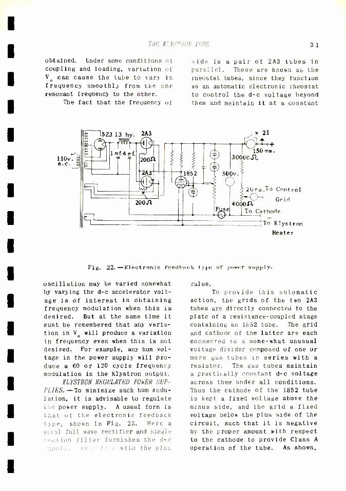
THE KLYSTRON TUBE 3 1
obtained. Under some conditions of
coupling and loading, variation of V. can cause the tube to vary in frequency smoothly from the one resonant frequency to the other.
The fact that the frequency of
_ 110v. á a.c. 2
side is a pair of 2A3 tubes in
parallel. These are known as the
rheostat tubes, since they function
as an automatic electronic rheostat
to control the d -c voltage beyond them and maintain it at a constant
x 2I
1 C+ 150 ma .
30000 52,
500v.
se
20 ma.To Control
400041 Grid
1To Cathode
To Klystron
Heater
Fig. 22.--Electronic feedback type of power supply.
oscillation may be varied somewhat by varying the d -c accelerator volt-
age is of interest in obtaining frequency modulation when this is
desired. But at the same time it
must be remembered that any varia-
tion in V. will produce a variation
in frequency even when this is not
desired. For example, any hum vol-
tage in the power supply will pro-
duce a 60 or 120 cycle frequency
modulation in the Klystron output.
KLYSTRON REGULATED POWER SUP-
PLIES.--To minimize such hum modu-
lation, it is advisable to regulate
the power supply. A usual form is
that of the electronic feedback type, shown in Fig. 22. Here a
uc;ual full wave rectifier and single
r.eci, ion filter furnishes the d -c
in with the plus
value.
To provide this automatic action, the grids of the two 2A3
tubes are directly connected to the
plate of a resistance- coupled stage
containing an 1852 tube. The grid
and cathode of the latter are each
connected to a some -what unusual voltage divider composed of one or
more gas tubes in series with a
resistor. The gas tubes maintain
a practically constant d -c voltage
across them under all conditions.
Thus the cathode of the 1852 tube
is kept a fixed voltage above the
minus side, and the grid a fixed
voltage below the plus side of the
circuit, such that it is negative
by the proper amount with respect
to the cathode to provide Class A
operation of the tube. As shown,

32 SPECIAL ULTRA HIGH FREQUENCY TUBES
the grid potential may be adjusted over a range of voltage for reasons
that will be explained.
Suppose, for any reason, that
the voltage of the d -c output ter- minals decreases. Then the grid drops in potential closer to the minus side and hence goes more negative with respect to the cathode. This decreases the plate current of the tube, hence the voltage drop in the plate resistor. As a result.
the plate approaches the positive side of the circuit. This lifts up
the connected grids of the 2A3 tubes
and makes them less negative with respect to their cathodes. As a
result, the voltage drop across the 2A3 tubes (which is their plate voltage) is decreased, so that more of the d -c voltage developed by the rectifier is available at the output
terminals, and thus practically entirely counteracts the tendency of the output d -c voltage to de- crease. On the other hand, if the
output voltage tends to rise, an opposite sequence occurs, the bias of the 2A3 tubes is increased, and
less voltage is available to the output.
The completeness of this coun-
teraction depends upon the gain of
the 1852 and 2A3 tubes, and also upon how close the grid is located to its gas tubes. If it is far down
on the potentiometer, then it does not get the full change in the ter-
minal voltage because of the voltage
dividing effect of the potentiometer for both the nominal d -c voltages and the changes in this voltage.
For quick voltage- variations,
such as that due to hum, the R -C network in the grid circuit tends to
hold it at a fixed value with re-
spect to the plus side of the cir-
cuit even when it is a considerable
distance down on the potentiometer.
But for the slower line voltage fluctuations this R -C network is
ineffective unless its time con- stant (R x C) is made unduly large. To counteract such fluctuations it is necessary for the grid to be up high on the potentiometer and thus close to the gas tubes.
The function of the potentio-
meter is not only to afford fine adjustment to the bias of the 1852
tube, but also to adjust the supply
to any desired d -c voltage within its range. If the grid is close to the gas tubes its bias is low,
the drop in the 1852 plate resistor is high, so that the 2A3 grid bias is great, and a large part of the rectified d -c is lost across these rheostat tubes, so that less is available across the output termi-
nals.
On the other hand, if the grid
is moved down on its potentiometer, the d -c output voltage is increased.
Thus high d -c output is-accompanied
by poorer regulation, especially to line voltage fluctuations. For
best results the unit should be designed for a fixed output voltage,
and the gas tubes chosen so that the
grid can be operated close to them.
Such a regulated power supply can take care of all reasonable values of line voltage variations, residual hum, and variations in the
current drain, particularly low frequency audio or video currents when such amplifiers are connected to it. It thus acts like a power supply of very low internal resis- tance, and values of .10 ohms down to a fraction of an ohm are readily obtained. For a Klystron tube the constancy of voltage depends upon the freedom from frequency modula-
tion desired, as will be discussed
THE KLYSTRON TUBE
in the next section.
Note that the control grid of the Klystron is operated at a posi- tive potential with respect to the cathode and draws appreciable direct current. This is merely a d -c load,
as the r -f signal voltage is not applied to this grid, but to the buncher resonator, and for closely spaced buncher grids the loading is negligible.
The regulated power supply shown in Fig. 22 can furnish about 500 volts. This is generally suf- ficient for the smaller Klystron tubes employed as local oscillators in receivers. The output of a typi- cal tube is about 30 to 75 milli - watts. The same tube, however, can furnish about 3 watts at 2,000 volts. The higher voltage power supplies introduce complications. Generally in such a case the grid voltage is furnished from a separate supply, since variability in its current drain will produce variability in its voltage when this is obtained by means of a voltage divider, even though the latter is connected to a constant voltage supply.
In energizing the tube, the following sequence of operations is important: 1). Apply heater voltage, 2). Set the control grid to zero volts. 3). Apply beam voltage and adjust this to the pro- per value. 4). Raise the control grid voltage until the proper beam and grid currents flow. For 500 volts representative values are 30 ma for the beam current and 5 ma for the control grid current.
FREQUENCY VARIATIONS. -It was shown above that variations in the beam voltage depends also upon the Q of the resonators. If these are tightly coupled, the relationship is as follows:
(% change in frequency) =
5.25 x 10-esf
Q VV 0
33
(% change in voltage)
(7)
where s is in meters, and f is in
cycles per second.
As an example of the use of Eq. (7) suppose 0.01% change in fre-
quency due to a change in the ac-
celerating voltage is permissible. What is the permissible percentage change in the voltage? Assume s = 3 cm = . 03 m, f = 3, 000 mc,
Q = 3,500, and Vo = 500 v. Then, from Eq. (7)
.01 -
or
5.25x 10-8x .03 x 3x 109
3500 500 (Percentage change in voltage)
(Percentage change in voltage)
.01 x 3500 500 5.25 x 10-6 x .03 x 3 x 109
= 1. 661%
x
As another example, calculate the change in frequency in the above case for a change of 1 volt in Vo = 500 volts. This represents a
percentage change in voltage of 1 500 = .002 = .2%. The percent- age change in frequency is
(Percentage change in frequency)
5.25 x 10⁻⁶ x. 03 x 3 x 109
3500 /500 .2
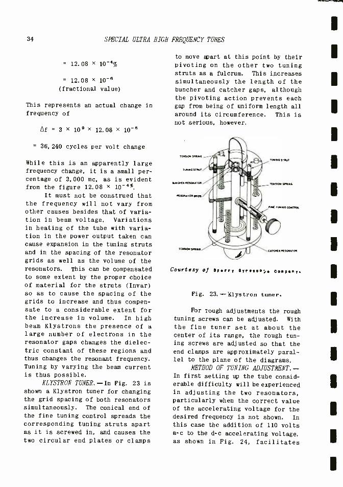
34 SPECIAL ULTRA
= 12.08 X 10⁻⁴%
= 12.08 X 10 -9
(fractional value)
This represents an actual change in
frequency of
Af = 3 X 109 X 12.08 X 10 -9
= 36, 240 cycles per volt change
While this is an apparently large frequency change, it is a small per-
centage of 3,000 mc, as is evident from the figure 12.08 X 10 -4 %.
It must not be construed that the frequency will not vary from other causes besides that of varia- tion in beam voltage. Variations in heating of the tube with varia- tion in the power output taken can cause expansion in the tuning struts
and in the spacing of the resonator grids as well as the volume of the resonators. This can be compensated to some extent by the proper choice of material for the struts (Invar)
so as to cause the spacing of the
grids to increase and thus compen- sate to a considerable extent for the increase in volume. In high beam Klystrons the presence of a
large number of electrons in the resonator gaps changes the dielec- tric constant of these regions and thus changes the resonant frequency.
Tuning by varying the beam current is thus possible.
KLYSTRON TUNER.--In Fig. 23 is
shown a Klystron tuner for changing the grid spacing of both resonators simultaneously. The conical end of
the fine tuning control spreads the
corresponding tuning struts apart as it is screwed in, and causes the
two circular end plates or clamps
HIGH FREQUENCY TUBES
to move apart at this point by their
pivoting on the other two tuning struts as a fulcrum. This increases
simultaneously the length of the buncher and catcher gaps, although the pivoting action prevents each gap from being of uniform length all
around its circumference. This is not serious, however.
TENSION SPRING
TUNING STRUT
AUNG'ER RESONATOR
RESONATOR GRIOR
TENSON !PMNN
Courtesy of Sperry Sy
TUNING STRUT
TENSION SPRING
FINE TUNING CONTROL
CATCHER RESONATOR
ye Company.
Fig. 23. -iüystron tuner.
For rough adjustments the rough tuning screws can be adjusted. With
the fine tuner set at about the center of its range, the rough tun- ing screws are adjusted so that the
end clamps are approximately paral- lel to the plane of the diagrams.
METHOD OF TUNING ADJUSTMENT.-- In first setting up the tube consid- erable difficulty will be experienced in adjusting the two resonators, particularly when the correct value of the accelerating voltage for the
desired frequency is not shown. In
this case the addition of 110 volts a -c to the d -c accelerating voltage. as shown in Fig. 24, facilitates

THE KLYSTRON TUBE 35
such adjustments. The 60 cycle voltage varies the accelerating voltage through a range of values.
If the correct value of Va is in
this range, it will occur twice per
cycle, and give two groups of oscil-
lations per cycle. This can be de-
tected on a crystal detector and ear
phones.
LARY
Cohrt.sy of ep.rr, e,ro.o.p.
Fig. 24.- Method of adjusting the
Klystron.
To adjust, first loosen the
rough adjustment screws until the
grids of each set touch one another.
Then back them away about .03" (this
depends upon the frequency). Then,
from data supplied with the tube,
choose an approximate value of beam
voltage and beam current (the latter
by adjusting the control grid).
Turn on the 110 v. 60 modulation
voltage and tune either resonator
by means of the appropriate rough
adjustment screws until oscillation
is observed. See that the end clamp
is maintained parallel in this latter
adjustment. Variations as great as
.01 inch may be necessary for the
resonator.
If oscillation cannot be de-
tected, vary the beam voltage in 200
volt steps and repeat the above pro-
cedure until oscillation is obtained.
Then turn off the modulation voltage.
and adjust the beam voltage to its
optimum value. Tune the resonators
for maximum output. The fine cont-
rol can then be used to vary both
resonators simultaneously until the
desired frequency is obtained, and
this may require further adjustment
of the beam voltage. A precaution must be noted. If the beam voltage
exceeds 600 volts, the output may be
great enough to damage a crystal de-
tector. In that case a neon lamp
indicator may be advisable, or the
crystal may be loosely coupled to
the Klystron output through a dipole.
Also after some experience, the eng-
ineer may find that some of the above steps in the procedure can be omitted.
THE REFLEX KLYSTRON. -- I n Fig. 25 is shown a reflex type of Kly- stron that employs but one resona-
tor. This functions both as a
Courtesy of seer'', G000000p* Coop....
Fig. 25.--Reflex-type of Klystron using only one resonator.
buncher and as a catcher resonator and the tube can be operated only as
an oscillator. The reflector elec-
36 SPECIAL ULTRA HIGH FREQUENCY TUBES
trode is operated normally at a
negative potential with respect to
the cathode, and thus repels the electrons in the beam back toward the resonator.
They thus pass through the resonator grids first in the direc-
tion toward the reflector electrode and acquire velocity modulation from
the resonator. They are then decel-
erated by the reflector electrode,
brought to a halt before they reach
it, and accelerated in the opposite direction toward the cathode.
Thus the distance from the resonator grids to the reflector electrode and back constitutes the drift space, and this can be physi-
cally short because the velocity of
the electrons in this region is
small owing to their deceleration. In traversing this space the elec- trons are bunched, and pass through the resonator grids in the reverse direction in clumps. They are thus able to give up energy to the reso-
nator and to the output circuit connected to it.
The frequency of oscillation is determined mainly by the reso- nator, but can be varied either by changing the accelerating or re-
flector voltages. However, since a negative reflector electrode does not draw any current and hence power, it is the preferred electrode
for voltage variation, and some frequency control is possible by this means. Note also that since one resonator is used, no double - peaked resonance curve is involved and if the accelerating voltage is maintained constant, only one set of
values for the reflector is obtained
at which oscillations occur in dis- crete steps.
One characteristic of the re-
flector Klystron is that its ability
to oscillate depends definitely on the magnitude of the load impedance
coupled to the resonator. If the
reflected impedance at the grids of
the resonator, corresponding to the
shunt resistance of a parallel L -C
circuit, is too low, the tube will
fail to oscillate. At some higher
value of load resistance, oscilla-
tion takes place at maximum effici- ency.
The reflex Klystron oscillator
clearly operates in the overbunched condition since the input voltage is
also the output voltage occuring in
the one resonator. Its efficiency is normally less than the two -reso-
nator Klystron, but for low power work the reflex may be more effi- cient, and is easier to tune. Hence
it is particularly suitable for use
as a local oscillator in a receiver.
METHODS OF MODULATION. -Klys- tron oscillators may be phase, fre-
quency, or amplitude modulated; Klystron amplifiers may be phase or amplitude modulated. Unfortunately,
frequency and amplitude modulation tend to occur simultaneously in an
oscillator, and special precautions have to be exercised to eliminate the undesirable form. Ordinarily, however, if frequency modulation is
desired, a small amount of amplitude modulation can be tolerated, as the
receiver is generally equipped with a limiter that removes the amplitude modulation.
If the control grid electrode voltage is increased, the beam current is increased, but not the velocity of the electrons comprising the beam, since the accelerating voltage has not been changed. Hence the transit angle t is unchanged and this would indicate that the frequency should be unchanged. But
an increase in electrons in the re-

THE MAGNETRON
sonator gaps produces an increase in the dielectric constant in these regions and hence a decrease in fre- quency of oscillation.
If the accelerating voltage is increased, the frequency tends to increase. Hence, by applying suit- able proportions of the modulating voltages to the two electrodes, amplitude modulation fairly free from frequency modulation may be obtained. By changing the phase of the voltage applied to one of the electrodes, frequency modula- tion substantially free of amplitude modulation may be obtained, although this is seldom necessary.
In the case of a Klystron amp- lifier, the carrier frequency is determined by the signal voltage applied to the buncher, and varia- tion in acceleration voltage or that on the control grid can produce only amplitude modulation, although some
accompanying phase modulation will be had because of the variation in
transit time through the drift space with change in acceleration voltage.
THE MAGNETRON
Another tube of very great im-
portance in the u.h.f. field is the
magnetron. As its name suggests, it
employs a magnetic field in order to function, and normally does not employ a control grid. Instead, it
has a central cylindrical cathode surrounded by a cylindrical structure that functions as a plate (anode) and has a multiplicity of cavity resona-
tors, all operating in conjunction with a magnetic field.
The magnetron was used to a
great extent in World War II to fur-
nish large amounts of power output at super -high frequencies in radar
37
equipment, and it is still used to a
very great extent at these frequen-
cies. Unfortunately, it is not readily modulated either in ampli-
tude or frequency, and lends itself primarily to pulsing. Within these limitations it has, however, a wide field of utility.
ORIGINAL DEVELOPMENT. - The magnetron was invented by Dr. Hull of the General Electric Company, and
originally was intended as a kind of relay tube, rather than for u. h. f.
purposes. Consider a cylindrical cathode C, Fig. 26, surrounded by a
concentric cylindrical plate P, that is made positive with respect to C
by means of a B' battery. Electrons emitted by the cathode will be attracted to P along radial electric field lines joining the two and will
move outwardly along these lines to ward P.
Fig. 26.--View of cylindrical form of magnetron.
Now suppose a magnetic field is set up such that the magnetic lines of force are perpendicular to
the plane of the paper, i. e. , paral- lel to the axis of the tube. As the electrons start to move along the radii of the tube, they cut perpen- dicularly through the magnetic lines. Since the electrons in motion constitute a current flow, and this current flow is perpen- dicular to the magnetic lines, the motor rule for force on a current

38 SPECIAL ULTRA
carrying conductor in a magnetic field applies.
NOTION IN A MAGNETIC FIELD.--For
electron flow the right hand may be
used. If the forefinger points in
the direction of the magnetic field,
and the center finger in the direc-
tion of electron motion, then the
thumb will indicate the right -angle
direction of the magnetron illus-
trated in Fig. 26, the force is as
shown in Fig. 27. Thus let e rep-
resent an electron moving radially
outward as indicated by the arrow M. The magnetic field is assumed
to be perpendicularly downward into
the paper, as indicated by the
Fig. 27.--Application of eight -hand
motor rule (assuming electron flow)
to a magnetron.
crosses. Then the force on the
electron is in direction perpen- dicular both to the direction of motion M and the magnetic flux, and
is therefore in the direction de-
noted by the arrow F.
This causes the electron to
veer around so that its direction of
motion is no longer radial, M, but
now has a component in the direction
of F. Thus, the old and the new
directions are indicated in Fig. 28.
Let m represent the original radial
velocity, i.e., the length of M
represents the magnitude of the
velocity; and the direction of M,
the direction of the radial velo-
city. Let F represent vectorially
HIGH FREQUENCY TUBES
the force acting on the electron. This produces an acceleration in the
direction of F, and therefore, in a
small interval of time, a velocity
of magnitude vl in the direction of
F.
The new velocity is the vector
sum of M and vl, or M'. But this
new direction of velocity M' pro-
duces a force F' by interaction with
the magnetic field that is now in a
direction perpendicular to M' as
Fig. 28.- Vector illustration show- ing that emitted electron will have
somewhat circular motion.
shown. This produces a component of velocity v2 along F'. This can
be combined with M' to give a new
velocity inclined to M', just as M'
is inclined to M, and so on. The
net result is that the electron no
longer moves in a radial direction,
but in a direction somewhat in a
circle.
If there were no voltage be- tween the plate and cathode to
accelerate the electron toward the plate, and instead the electron
was ejected from the cathode with an
initial velocity vl, then the mag-
netic field would veer the electron
around, as shown in Fig. 29, so that
it described a circle cl, having a
radius rl. If the electron were ejected from the cathode with a
higher velocity v2, then it would

THE MAGNETRON 39
be revolved by the magnetic field into a larger circular path C2,
z
having a larger radius r2.
X
X X
x
Fig. 29.--Effect of magnetic field on emitted electron when there is no
difference of potential between cathode and plate.
An interesting fact, revealed by a mathematical analysis, is that the time required for one revolution in either case would be the same, i.e., the number of revolutions per second would be the same. Let f =
number of revolutions per second. Then
f = He
= 2.8 x 10⁶H 2mn
(8)
where H is the magnetic field mea- sured in gausses, e is the charge, and m is the mass of an electron. Note that the number of revolutions per second f, can be varied by changing the strength of the mag- netic field H, but that since the initial velocity v does not appear in Eq. (8), f is clearly independent of v, as stated above.
The magnetic field changes the direction, but not the magnitude of
the velocity of the electron. This
means that the kinetic energy of the
electron, equal to 1/2 mv2, is not
altered by the magnetic field, hence
the latter does not have to furnish
any energy to the electron when it alters its path of motion. In other
words, a permanent magnet, if strong
enough, can serve to make the elec- tron move in a circle.
ACTION OF A COMBINED ELEC- TRIC AND MAGNETIC FIELD. -Now sup- pose that the plate is made positive with respect to the cathode. There
is now established an electric field
between the two electrodes that acts
on the electron to accelerate it radially. Assume now that the elec-
tron is not emitted with any appre-
ciable velocity from the cathode. but that it acquires velocity by the
acceleration imparted to it by the
electric field. In other words, in-
stead of having an initial, fixed velocity, the electron now acquires an increasing velocity as it moves toward the plate.
The magnetic field meanwhile acts to veer it around as before. The path is now more complicated. Analysis shows it to be a cycloid. This is a curve generated in space by a point on the circumference of a circle that rolls along a
straight line, or on the outside or inside of another circle. In
the case of cylindrical electrodes the generating circle may be con- sidered to roll on the outside of the circular cathode.
A possible curve is the four -
cusped curve shown in Fig. 30 *.
*Actually, after one leaf has been described, the electron may be absorbed by the cathode, but if the latter were not present, the complete curve would be described and repeated indefinitely.

40 SPECIAL ULTRA HIGH FREQUENCY TUBES
For a suitable combination of mag- netic field H and plate voltage E,
the size of each lobe or cusp of the
curve is such that the electron just
Fig. 30.--Showing cycloidal curve resulting when plate voltage and magnetic field are acting on emitted
electrons.
grazes the outer circular plate P,
as indicated in Fig. 30.
If the magnetic field H is
increased, the lobes are reduced in size, and the electron never reaches the plate. This is striking:
in spite of the plate voltage, elec-
trons never reach the plate and there
is no plate current, owing to the
action of the magnetic field. A de-
crease in H, on the other hand, will
permit plate current to flow. This
suggested to Dr. Hull that the tube
might be used in a manner similar to
a grid -controlled tube, particularly
as anon -off relay, with' the magnetic
field acting as the control element.
DISCUSSION OF MOTION.--The mo-
tion of the electrons in such a tube
has been found conducive to the production of u. h. f. oscillations.
It is therefore of importance to
study the motion of the electron in
a combined electric and magnetic field. Fig. 30 indicates that the
electron performs a series of cir-
cular gyrations in addition to a
progressive motion around the cath-
ode; this is the cycloidal curve.
The number of circular gyrations
(lobes) per second is the same as
that for Fig. 29, as given by Eq.
(7), i.e., the time required to
execute one revolution is the same
whether there is no plate voltage
and only the magnetic field, and
the electron is ejected into the
space with any given velocity, Fig. 29, or the electron emerges into space with zero velocity, but
plate voltage is applied so that the
electron is then accelerated toward
the plate and veered around by the
magnetic field, Fig. 30.
The presence of plate voltage
causes the electron to move around
the cathode while it is also moving
in a circular manner. The motion
around the cathode, or precession,
as it is called, is clearly at a
slower rate that its circular motion; indeed, at certain points
of the path the electron may for a
very short time interval move in the
opposite direction with respect to
the cathode.
This is shown in Fig. 31. Let
If
, A
Fig. 31.-- Diagram showing basis of
statement that we can have an average
angular velocity as measured from
cathode's center.

THE MAGNETRON 4].
C represent the circular cathode surface whose center is A, and DEF
represent the path of the electron,
starting at the cathode at D. Fur-
ther, let B represent, at some in-
stant, the center of the rolling circle that generates the electron path DEF. While B actually moves around A, it will be convenient to
consider it as stationary, although this produces a certain amount of error in the analysis to follow.
The electron, starting out from the cathode at D, proceeds to
E. In doing so it moves through an angle DAE, as measured from the center A of the cathode. As mea-
sured from B, however, the angle is
DBE. Thus the electron may be re-
garded as sweeping out two series of angles simultaneously, one with respect to A as a center, and one with respect to B as a center. Note
that angle DAE is counterclockwise,
and that angle DBE is clockwise.
The electron now proceeds from E to F. Viewed from A, it sweeps out the angle EAF, which is now clockwise. Viewed from B, it sweeps
out angle EBF, which is clockwise
as was angle DBE. Thus, with re-
spect to B, the angle swept out is
always clockwise; with respect to A,
the angle will be at times counter-
clockwise, but it is clear from the
figure that the general trend of this angular motion is clockwise.
One can therefore speak of an average angular velocity as measured
from A. This represents the number
of radians swept out by the electron
in one second as measured from the
center of the cathode, and may be
represented by w. The value is
w = E/Hr (9)
where E is the electric field in-
tensity; H is the magnetic field
intensity, and r is the radius of
the approximately circular path, such as, approximately, DB or BE,
etc.
It will be shown below that the
electrons move as a kind of a cloud
within and fairly close to the
circular plate. In a practical magnetron for generating u. h. f. this
plate is split into segments. As
the cloud sweeps by the splits in
the plate or segments. it induces
a -c voltages in them of the desired
high frequency. Hence, in this type
of split plate magnetron, it is
important that w as given by Eq. (9)
be coordinated with the frequency
of the plate segments, and thus w is an important quantity.
On the other hand, the fre-
quency with which the electron per-
forms its circular motion that gives
rise to the lobes shown in Fig. 30
is of importance in defining the mode
of operation of the magnetron. Recall that f represents the number
of revolutions per second. Each
revolution corresponds to 27 radi-
ans. Hence the number of radians swept out per second (as measured from B in Fig. 31) is clearly 27f.
This is by. definition the angular velocity, call it w$, so that Eq.
(8) can be rewritten as
w = 17.6 X 10⁸H (10)
where w is in radians per second,
and H is measured in gauss (lines
per square centimeter).
Suppose--as will be described
presently--the magnetron oscillates
at some frequency f, to which cor-
responds the electrical angular frequency w = 27f. Then the ratio
of the electrical w to the above
angular velocity wm is called the
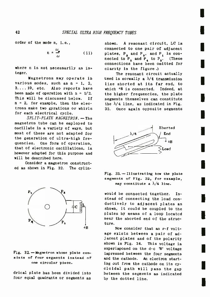
42 SPECIAL ULTRA HIGH FREQUENCY TUBES
order of the mode n, i. e. ,
c n =
W
where n is not necessarily an in-
teger.
Magnetrons may operate in
various modes, such as n = 1. 2,
3....10, etc. Also reports have been made of operation with n = 1/2.
This will be discussed below. If
n = 2, for example, then the elec-
trons make two gyrations or whirls for each electrical cycle.
SPLIT -PLATE MAGNETRON. --The magnetron tube can be employed to oscillate in a variety of ways, but most of these are not adapted for the generation of ultra -high fre- quencies. One form of operation, that of electronic oscillations, is
however adapted for this purpose and will be described here.
Consider a magnetron construct- ed as shown in Fig. 32. The cylin-
+B
Fig. 32. - Magnetron whose plate con- sists of four segments instead of
one circular piece.
drical plate has been divided into four equal quadrants or segments as
shown. A resonant circuit, LC is
connected to one pair of adjacent plates, P2 and P3, and P1 is con-
nected to P3 and P4 to P2. (These
connections have been omitted for
clarity in the figure.)
The resonant circuit actually used is normally a V/4 transmission
line shorted at its far end, to
which +B is connected. Indeed, at
the higher frequencies, the plate segments themselves can constitute the X/4 line, as indicated in Fig.
33. Once again opposite segments
Shorted
End
+B
Load
Fig. 33.--Illustrating how the plate segments of Fig. 32, for example,
may constitute a X/4 line.
would be connected together. In-
stead of connecting the load con- ductively to adjacent plates as shown, it could be coupled to the plates by means of a loop located near the shorted end of the struc- ture.
Now consider that an r -f volt- age exists between a pair of ad-
jacent plates and of the polarity shown in Fig. 34. This voltage is superimposed on the d -c 'B' voltage impressed between the four segments and the cathode. An electron start- ing out from the cathode on its cy- cloidal path will pass the gap between the segments as indicated by the dotted line.
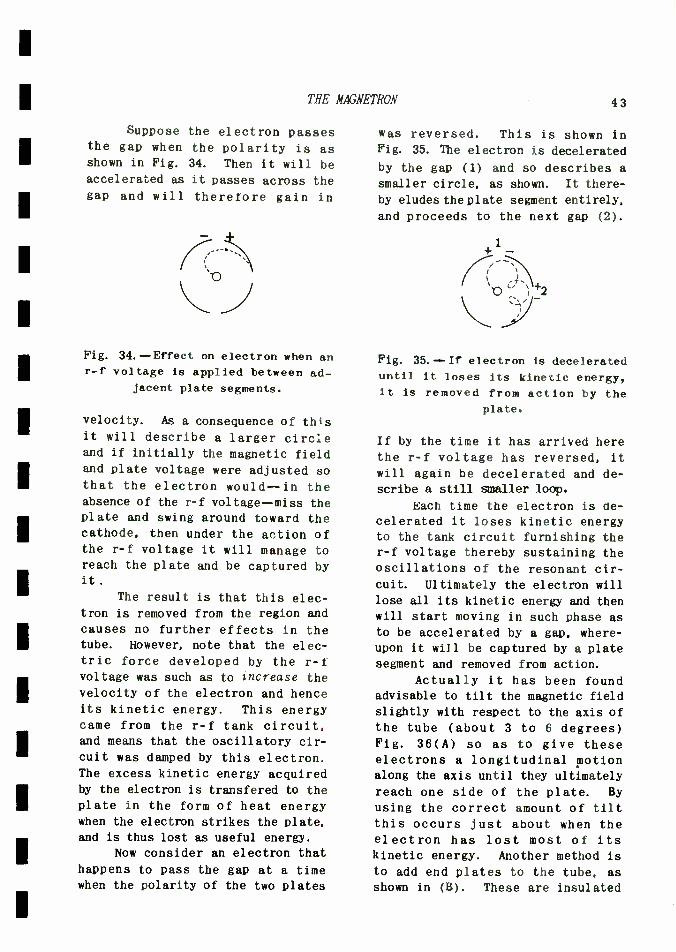
THE MAGNETRON 43
Suppose the electron passes the gap when the polarity is as shown in Fig. 34. Then it will be
accelerated as it passes across the gap and will therefore gain in
Fig. 34.--Effect on electron when an r -f voltage is applied between ad-
jacent plate segments.
velocity. As a consequence of this it will describe a larger circle and if initially the magnetic field and plate voltage were adjusted so that the electron would --in the absence of the r -f voltage--miss the plate and swing around toward the cathode, then under the action of the r -f voltage it will manage to reach the plate and be captured by it
The result is that this elec- tron is removed from the region and
causes no further effects in the tube. However, note that the elec- tric force developed by the r -f voltage was such as to increase the velocity of the electron and hence its kinetic energy. This energy came from the r -f tank circuit, and means that the oscillatory cir- cuit was damped by this electron. The excess kinetic energy acquired by the electron is transfered to the
plate in the form of heat energy when the electron strikes the plate,
and is thus lost as useful energy.
Now consider an electron that
happens to pass the gap at a time when the polarity of the two plates
was reversed. This is shown in Fig. 35. The electron is decelerated
by the gap (1) and so describes a
smaller circle, as shown. It there-
by eludes the plate segment entirely,
and proceeds to the next gap (2).
Fig. 35. - If electron is decelerated until it loses its kinetic energy, it is removed from action by the
plate.
If by the time it has arrived here
the r -f voltage has reversed, it
will again be decelerated and de-
scribe a still smaller loop.
Each time the electron is de- celerated it loses kinetic energy to the tank circuit furnishing the r -f voltage thereby sustaining the oscillations of the resonant cir- cuit. Ultimately the electron will lose all its kinetic energy and then will start moving in such phase as
to be accelerated by a gap, where- upon it will be captured by a plate segment and removed from action.
Actually it has been found advisable to tilt the magnetic field
slightly with respect to the axis of
the tube (about 3 to 6 degrees) Fig. 36(A) so as to give these electrons a longitudinal motion along the axis until they ultimately
reach one side of the plate. By
using the correct amount of tilt this occurs just about when the electron has lost most of its kinetic energy. Another method is to add end plates to the tube, as
shown in (B). These are insulated

44 SPECIAL ULTRA HIGH FREQUENCY TUBES
from the plate segments, and also given a positive potential with respect to the cathode. They thus
Axis of
Tube
Axis of Magnetic
Field
Fig. 36(A).--If axis of tube is ro-
tated slightly with respect to axis of magnetic field, improved operation
can result.
End
Plates
Fig. 36(B).--Same effect as that ob-
tained with Fig. 36(A) can be had by addition of end plates.
attract the electrons to the end of the tube and remove them from the oscillatory circuit region when they have lost their ability to feed energy into the circuit.
ADDITIONAL FACTORS OF OPERA- TION.--The mechanism just described shows that electrons of favorable phase continue to whirl around in
the tube and deliver energy to the
oscillatory circuit over several
electrical cycles, whereas electrons
of unfavorable phase--those that absorb energy from the oscillatory
circuit--are essentially removed in the first revolution. Thus,
even if as many electrons of un- favorable phase are emitted per second as electrons of favorable phase, there still results a favor-
able power balance in that the
oscillatory circuit receives more energy than it has to give out,
and thus can maintain its oscilla- tion.
Actually electrons are emitted
at all times and hence pass the gap with various degrees of phase - favorable and unfavorable. The
action of the gap is to advance the
phase of an electron that absorbs
some energy from the gap (but not
enough to cause it to strike the
plate) so that ultimately the elec- tron begins to pass gaps between plate segments at the right moment in the electrical cycle to be de-
celerated. In other words, the
electron begins to furnish energy to the electrical tank circuit.
This indicates a bunching mechanism; electrons of completely unfavorable phase are removed almost immediately, and electrons that can be brought into favorable phase are accelerated so that they catch up
with those that are already of favorable phase to produce a kind of electron cloud that precesses at a high rate of speed between the seg- mented anode and cathode, and close to the anode segments. As this cloud passes by each gap it induces a current in the tank circuit, there-
by feeding energy into it and main-
taining its oscillation.
A possible situation is illus- trated by Fig. 37. Srppose an elec- tron starts at A just as the r -f

THE MAGNETRON 45
voltage between P1 and P2 is pass- ing through zero. Suppose by the time the electron reaches point B,
P2 is at a negative peak with re-
spect to P1 as shown. The elec- tron will be decelerated and hence
Courtesy of R.I. Sarbacher
Fig. 37.- Possible path of an elec- tron in a 4- segment anode magnetron.
will deliver energy to the gap. The
electron proceeds to C and suppose by this time another quarter elec- trical cycle has occured so that the r -f voltage between P2 and P1 is
zero once again. The electron now
proceeds from C to D. If this takes
another quarter electrical cycle,
P2 will be positive with respect to
P1. Recall that P3 is connected to
P1 and P4 to P2. Hence P2 will also
be positive with respect to P3, and
thus the electron at D will again be
decelerated. This process continues
with respect to P3 and P4, and with
respect to P4 and P1, and so on
until the electron has lost all its
energy or has passed up and out of
the sphere of action owing to mag-
netic field tilt or end plates.
Note that one electrical cycle
(= an radians) corresponds to two
lobes of the electron path (= 47r
radians). Thus for w = rad./sec.,
wm = rad./sec., so that
w lu n = = = - = 2
w 2rr
or the tube in the above example operates in a mode of 2.
ELECTRONIC OSCILLATIONS OF HIGHER ORDER.--Electronic or transit
time oscillations of higher order mean that n is greater than unity.
This in turn means that the angular
velocity wm is many times the elec-
trical angular frequency w, or the
electrons produce many whirls or gyrations per electrical cycle.
Such rapid gyrations can be brought about by increasing the magnetic field to about 60 or 70 per cent
greater than the critical value,
i.e., the value that veers the elec-
trons around so that they just graze
the plate segments.
Under the action of such a
strong magnetic field the electrons
describe many sharp circular whirls
before they reach a gap between two
segments and deliver energy to the
latter. This is illustrated in
Fig. 38. It is clear the number of
5-)y
Fig. 38.--If magnetic field is in-
creased above the critical value,
electrons gyrate very rapidly.
such gyrations or convolutions does
not have to be related to the elec-

46 SPECIAL ULTRA HIGH FREQUENCY TUBES
trical frequency, i.e., n can be some number greater than one but not
necessarily an integer, e. g. n = 7. 8.
What is important is that the aver-
age precessional angular velocity c, as given by Eq. (9) be synchronized
to the electrical frequency.
The efficiency of operation for
these higher modes of operation (n > 1) is very good, as may be seen
frow Fig. 39. Here P refers to the
number of pairs of segments. It
4 -SLOT MAGNETRON p.2
_^ 2-SLOT MAGNETRON 1..1. 11
) 2 4 E e g 12 14 1e b 20 n
Courtesy of Ultrashort Electromagnetic Waves,
I. S. Yourorteeff.
Fig. 39.--Plot of efficiency for a
2- and a 4 -slot magnetron.
will be observed that the four segment magnetron (P = 2) may have
an efficiency as great as 60 per cent for n greater than 10.
CATHODE BEATING.--The motions
of the electrons in the neighborhood
of the cathode of a magnetron are quite involved. In an ordinary vacuum tube the electrons proceed in paths essentially parallel to one
another from the cathode to the plate, and hence have little ten-
dency to collide with one another.
In the case of a magnetron there are electrons gyrating toward the cathode, and others leaving it start
a similar motion. Thus electrons are moving in all directions in the
vicinity of the cathode and colli-
sions are possible, of a glancing
type that impart excessively high velocities toward the cathode. At
any rate, it is found that under
certain conditions the cathode may
be bombarded by high -speed electrons
to an extent that its temperature
is raised unduly and its emission increased accordingly. This appears
to aggravate the bombardment, and in
a very short time--before circuit adjustments can be made --the cathode
may burn out. As a protective means, an automatic regulator in the
plate circuit has been employed to
reduce the plate voltage when the
plate current suddenly increases
owing to this cause. Unfortunately this action is
most apt to take place when the tube
is operated under optimum conditions
affording maximum output. For
safest operation it appears that the
cathode should be operated so that
the plate current is limited by the
emission, rather than by space charge effects. This limits the
amount of space charge around the
cathode and hence the tendency for the cathode to burn out. Even un-
der these conditions the space charge
modifies appreciably the fundamental
action of the electrons described above, and makes the theory of operation far from complete.
MAGNETRONS WITH CAVITY RESO- NATORS.--An interesting type of magnetron employing cavity reso- nators has been described by N.F.
Alekseev and D.D. Malairov in the
Journal of Technical Physics (Rus-
sian). A translation has been made
by I.B. Bensen, of the General
Electric Company.* Tubes have been built in both
the demountable and sealed -off
* "Generation of High -Power Oscill- ations with a Magnetron in the Centi- meter Band." Prox. I. R. E. , March 1944.

TBE MAGNETRON 47
types. The former type permitted various types of electrodes to be
tested. Its form is shown in Fig.
40. The two right angle tubes
Courtesy of IRE Proc., March 1944.
Fig. 40.- Cross -section view of de-
mountable type tube.
coming out at the left and right near the top are for the purpose of
feeding cooling water to a tube surrounding the solid copper anode,
and also serve as electrical con-
nections. The bottom flange is bolted on a continuously running oil
diffusion pump to maintain the vacu-
um.
One form of copper anode is
shown in Fig. 41. A central hole is drilled through the copper block,
and this is surrounded by four cavities connecting to it through narrow slots. Eacn of these con-
stitutes a kind of cavity resonator
of a shape to be discussed. The
cathode is inserted in the central
hole, and the magnetic field is per-
pendicular to the plane of the paper,
14
SLOT WIDTH EQUALS IA
i= 40Y14
Courtesy of IRE Proc., March 1944.
Fig. 41. -One form of copper anode
used in magnetrons.
as in the other types of magnetrons
described previously. The numbers
appearing in Fig. 41 give the dimen-
sions of various components of the
tube in millimeters.
PERFORMANCE OF FOUR- CAVITY MAGNETRON. -Some figures concerning its operation and performance are
given in Table 1. The dimension dk refers to the central hole in which the cathode is inserted. This dimension depends upon the anode potential Et and the magnetic
field strength H, as follows
dk -
K VEb
H
(12)
where K is a constant. The di-
mension da refers to the radius of

48 SPECIAL ULTRA HIGH FREQUENCY TUBES
the cavity. Its ratio to dk should
be somewhat greater than unity; for
a single cavity, the ratio should
not be less than 1.3, and for the
four - cavity system of Fig. 41 it may
be as low as 1.1. The actual value,
as noted from Table 1 was 1.5. For
a given wave length X, a four -cavity
anode permits larger values of dfl
and Ç. and this results in increas-
ed power output.
Note that at the higher plate voltage 4,400 volts a higher value of H, namely 1950 gauss was required.
The output was increased to 300
watts, and the efficiency to 20 per
cent, but the trouble previously of
over -heating of the cathode was experienced. The anode, being a
block of copper, is a good heat
conductor and could easily be cooled
to a safe temperature, so that this
did not limit the output as is the
case for an ordinary negative -grid
tube.
The authors state that in the
centimeter -wave band a first order
mode of operation, n = 1, is pre-
ferable. This is contrary to the
curves given previously in Fig. 39
for a split -plate magnetron. For
n = 1, the theoretical relationship
between wavelength A and magnetic
field strength H is
HA = 10,700 (13)
although in practice, higher values
are encountered. This is indicated
in Table 1, where HA has the value
of 12,100 for Eb = 2,650 volts, and
17,500 for Eb = 4,400 volts.
Nevertheless the product HA,
and hence the value of H for a given
value of X, is less than for the
higher modes of operation, n >1. The
authors point out that there is an
advantage in operating in the first-
order mode, because not only are
less powerful magnetic fields re-
quired, but the over -heating of the
cathode is less, and thus the limi-
tation on the tube's output is ex-
tended. Indeed, oscillations for
which HA = 6,500 i.e. an even lower
value of H could be employed.
DISCUSSION OF CAVITY RESO-
NATOR.--The cavity resonators em-
ployed in this design are of a re-
entrant type similar to those em-
ployed in a Kylstron tube. Thus
the cavity proper, B, Fig . 42, is
Fig. 42.- Cavity contains most of
inductance, whereas slit contains
most of the capacity.
the region of greatest magnetic flux, and thus contains most of the
inductance whereas the slit, A, is
the region of she greatest concen-
tration of electric field lines,
and therefore contains most of the
capacitance.
Two important advantages are
obtained by this design: 1). As
stated previously, a high impedance
is developed across the gap or slit,
even though the Q of this type of
cavity may be 1Qwer than that of the
more usual type. As a result,
a high r -f voltage appears across
the slit, and has a maximum decele-

THE MAGNETRON
rating effect on the electron cloud
passing by. Owing to the short length of this slit, transit -time
loading of the resonator by the electron cloud is at a minimum, and
maximum energy transfer takes place.
49
voltage and magnetic field intensity
can be varied considerably. In the
case where several cavity resonators
are employed, some means of connect-
ing them together similar to the
cross - connections for a four - segment
TABLE I
ds /dk Eb
volts
lb
Milli-
amperes
7
H
Gauss
ñ
cm.
FIX Output
Watts
Per
Cent
Effi-
ciency
Remarks
1.5
1.5
2650
4400
360
330
1350
1950
9.0
9.0
12100
17500
170
300
18
20
Fig. 40
Serious
Back
Heating
2). A reentrant type of cavity re-
sonator may be regarded as a tran-
sition between a lumped L -C circuit
and the conventional type of cavity
resonator. It will be recalled that
at ultra -high frequencies lumped circuit elements became inconvenient-
ly small and distributed circuit elements, such as tuned lines and
cavity rescnators, become of reason-
able size. A reentrant type resona-
tor, being a transition type between
the two, can be expected to be
smaller than the conventional type
cavity resonator. As such, it is
actually of a more convenient size
for a magnetron tube, particularly when a number are employed around
the central cathode hole. Thus it
will be found that an apparently undersize cavity of this shape will
be resonant, say, to a 9 cm wave.
It is to be noted that the frequency is determined by the cavi-
ty dimensions, and that the plate
magnetron may be expected. In such
a case the load could be coupled by
means of a loop to one cavity reson-
ator and yet extract energy from all.
The instantaneous r -f polarity
of the slits would then be as indi-
cated in Fig. 43. The electron
Fig. 43. -Diagram of a 4- segment split anode magnetron.
cloud then whirls around in the
central hole, with individual elec-

50 SPECIAL ULTRA
trons performing radial excursions
representing the convolutions prev-
iously mentioned, and the cavities
are excited by the precessional motion. In the article mentioned.
as many as eight cavities are shown,
but there is no reason to believe
that a greater number are not employ-
ed at present.
One can also presume that
electrons that have their kinetic
energy extracted by the cavity reso-
nators strike the plate with a low
velocity and hence cause relatively
little heating. This can account
for the high efficiency of the
magnetron oscillator. ADVANTAGES AND DISADVANTAGES OF
THE MAGNETRON TUBE. --One of the advantages of the magnetron tube has
already been mentioned: its rela-
tively high efficiency at u.h.f.
Operation. beyond 30,000 me (1 cm)
has been reported, with appreciable
power output.
Another advantage of the mag- netron tube is the fact that it can
be pulsed and can furnish exceeding-
ly high outputs during the pulse period. This is an important advan-
tage of this tube over the Klystron.
On the other hand, the magne-
tron does not appear to be able to
operate as an amplifier, but solely
as an oscillator. Nevertheless--as
pointed out previously--this is an
important function, for it permits both the generation of u.h.f. energy
and its detection by the superhetero-
dyne method of reception.
Another disadvantage of the
magnetron is the need for a magnetic
field. However, it should be ap-
parent that u.h.f. tubes cannot be
as simple as the negative -grid tubes normally used at the lower frequencies, and complications must be accepted as inevitable in the
HIGH FREQUENCY TUBES
high- frequency end of the spectrum.
A further disadvantage is the
danger of cathode over -heating men-
tioned previously. Further circuit
complications are required -to pre-
vent the cathode from being burned
out, and therefore make the system more involved. In spite of all this
the magnetron is probably one of the
most important tubes for use at the
highest frequencies, and many peacetime uses for it may be ex-
pected.
CONCLUSIONS
This concludes the series of
assignments on Ultra -High Frequency
Techniques. The first discussed was
general features of u.h.f. propaga-
tion and then the use of transmission
lines, both tuned and nonresonant,
in the lower end of u.h.f. region of the spectrum. The next assign-
ment took up the subject of wave guides and cavity resonators, and
dealt with such matters as modes of propagation, attenuation, iris
diaphragms, taper line connections,
and methods of launching waves and extracting energy from wave guides and cavity resonators. These elements are useful at the highest frequencies in use today.
The third assignment continued with a discussion of u.h.f. radia-
ting systems. Dipole antenna arrays were first taken up with regard to
the lower end of the u.h.f. region
of the spectrum, and then radiation from wave guides, horns, and para- bolic reflectors was discussed. These are employed at the highest frequencies.
The fourth assignment concerned itself with some general considera-
tions of tubes ano associated cir-

CONCLUSIONS 51
cuits, such as amplifier gain, plate -to -grid capacity feedback, loading due to cathode lead in- ductance, signal -to -noise ratio, and the grounded -grid amplifier.
The fifth assignment proceeded with an analysis of transit -time loading, and its effects upon the design of both receiving and trans- mitting type negative -grid tubes for operation at ultra -high fre- quencies. Actual tubes were ana- lyzed as to design features, and finally the factors involved in air -and water -cooling were dis- cussed.
The sixth and final assign- ment concluded the series with an
analysis of those special type tubes, such as the inductive -output tube, the Klystron, and the magne- tron tube, that are particularly adapted to the amplification or generation of ultra -high frequen- cies. Although the mathematical theory of this tube is beyond the scope of this course, nevertheless it is felt that the student should gain a fairly good idea of the action of these tubes from the dis- cussion given in the assignment.

SPECIAL ULTRA NIGH FREQUENCY TUBES
EXAMINATION
1. A beam of uniform electron density and velocity passes by a
suitable mechanism --such as a control grid--that chops up the beam into dense and rarefied portions. The velocity of the beam is 15 X 108cm. /sec., which corresponds to a beam voltage of 625 volts. The signal frequency applied to the grid is 2.000 mc.
(A) What is the distance between two successive dense portions or two successive rarefied portions of the electron beam? HINT: This may be considered the beam wave length, and cor- responds to the distance covered by an electron in one cycle of the signal, similar to wave length calculations for electromagnetic waves, sound waves etc.
(B) The velocity of the electrons in the beam varies directly as the square root of the beam voltage. The above electrons subsequently pass a gap in a cavity resonator that is 1.5 mm. long. It is desirea that this length be 10 per cent of the beam wave length in order to minimize transit - time effects and hence input loading. To what value must the beam voltage be raised in order that this be accom- plished?

SPECIAL ULTRA HIGH FREQUENCY TUBES
EXAMINATION, Page 2
1. (B) The velocity of the electrons in the beam varies directly as the square root of the beam voltage. The above electrons subsequently pass a gap in a cavity resonator that is 1.5 mm. long. It is desires that this length be 10 per cent of the beam wave length in order to minimize transit - time effects and hence input loading. To what value must the beam voltage be raised in order that this be accom- plished?
2, (A) In general, how does the size of a reentrant cavity resonator compare with that of a conventional type cavity resonator? Is this an advantage?
I
I
I
1
i I
I
I
I
I
I
I
I 1
I
I
I
SPECIAL ULTRA HIGH FREQUENCY TUBES
EXAMINATION, Page 3
2. (B) What further advantage does a reentrant cavity reso- nator have when it is to be excited by an electron beam?
(C) What is the preferred method of extracting energy from a reentrant cavity resonator?
3. (A) In an inductive -output tube, what is the advantage of first accelerating the electrons to a high velocity and then decelerating them to a lower velocity before they are collected?

SPECIAL ULTRA HIGH FREQUENCY TUBES
EXAMINATION, Page 4
3. (B) What is the advantage of employing a magnetic field in this tube?
4. (A) How is input loading minimized in an inductive -out- put tube?
(B) What effect does the method employed have upon the transconductance and input capacitance of the tube?

SPECIAL ULTRA HIGH FREQUENCY TUBES
EXAMINATION, Page 5
4. (C) How is the tube modulated? Why aren't other methods
of modulation effective?
5. (A) What is the method employed in the Klystron tube to
produce variations in the density of the electron beam? Why
is this method particularly well suited to the higher fre- quencies; as compared to the control grid or 'gate' method employed in the inductive -output tube?
(B) A Klystron amplifier is connected to a receiving an- tenna dipole of 70 ohms internal resistance. The operating temperature may be taken as 300° K. The beam current is
30 ma., and the noise at the catcher grid and beyond may be
represented by an equivalent resistance of 150 ohms. The
band width is 20 mc. What must be the antenna generated voltage to yield a 1,000:1 signal /noise power ratio (maxi-
mum)?

SPECIAL ULTRA HIGH FREQUENCY TUBES
EXAMINATION, Page 6
5. (B) (Continued)
6. (A) A Klystron tube operates as an amplifier in the funda- mental frequency mode. The beam voltage is 1,600 volts, the signal voltage developed across the gap is 100 volts peak. The frequency is 3,500 mc, and the drift space is 3 cm. Is the tube operated under- or over - bunched or at its optimum condition?
SPECIAL ULTRA HIGH FREQUENCY TUBES
EXAMINATION, Page 7
(B) The above tube is to be operated as an oscillator with the same beam voltage. The operating frequency is found to
equal 3,500 mc, and the value of n is found to equal 5. Find the phase angle 02 in radians and in degrees.
7. A Klystron tube for which S = .024 m., Vo = 900 volts oscil- lates at a certain frequency. The value of n is known to be 2. The beam voltage is lowered to 625 volts, whereupon the tube begins to oscillate once more. The value of n must therefore be three at this voltage. Calculate the frequency at which the tube is oscillating.

SPECIAL ULTRA HIGH FREQUENCY TUBES
EXAMINATION, Page 8
7. (Continued)
8. (A) A Klystron tube has a drift space of 2.5 cm and os- cillates at 3,300 mc. Its power supply developes 550 volts, and measurements indicate a ripple voltage of ± 1.2 volts peak. This produces a measured frequency variation of ±
25,000 c. p. s. What is the Q of the resonators?
SPECIAL ULTRA HIGH FREQUENCY TUBES
EXAMINATION, Page 9
8. (A) (Continued)
(B) Describe a method of obtaining amplitude modulation in a Klystron oscillator, that is reasonably free of frequency modulation.
9. (A) What is the mechanism that produces bunching in a mag- netron tube?
SPECIAL ULTRA HIGH FREQUENCY TUBES
EXAMINATION, Page 10
9. (A) (Continued)
(B) How is the average angular velocity of the cloud of electrons related to the frequency of the voltage of the output resonant circuit?
10. (A) Describe briefly in your own words the phenomenon of cathode heating.
(B) Attempts to amplitude -modulate a magnetron tube are not in general successful in that the amplitude of the r.f. output current or voltage is not in direct proportion to the amplitude of the modulating voltage. Why is this not impor- tant when the magnetron is to be pulsed; i.e., why is pulsing of the tube nevertheless feasible?

.