rada 50 thermostatic mixing valve installation and … rada® 50 thermostatic mixing valve...
TRANSCRIPT
1
Rada® 50 Thermostatic Mixing ValveInstallation and Maintenance
Water Temperature ControlsRecirculation Systems
Thermostatic
This Rada 50 Valve has been supplied for this application based upon information provided to Armstrong at the time the order was placed.
This Rada 50 Valve is configured for use in a “dead leg” piping configuration as indicated in the drawing on page 4.
This Rada 50 Valve is not configured for use as the primary controller in a central pumped re-circulation system.
This Rada 50 Valve is not designed to deliver tepid water to Emergency Fixtures.
For further information, please call our technical department Toll Free at 1-888-HOT-HOSE.
ALIB-50-B
Model No. Rada 50
Serial No.
Ship Date
1017
B125
Important Note: Rada 50 is not designed to be the final water temperature controller in an institutional hygiene application.
2
Water Temperature Control - Groups of Fixtures
Thermostatic Rada 50Rada 50 Thermostatic Mixing Valve for institutional group fixture water temperature control when ASSE 1016 certified individual fixture controls are installed at each point of use
Rada 50 is also applicable for accurate water temperature control in single open outlet or “dead leg” multiple-point-of-use industrial process applications. Capable of close outlet water temperature control at flow rates between 2 and 98 gpm (7.5 and 371 lpm).
Rada 50 Offers:• Dual thermostatic elements provide redundancy in the
event of individual thermostat failure• Typical outlet temperature control +/-2°F• Adjustable single temperature lockout (removable key)• Thermal shutdown mode upon inlet supply failure
* Shutdown mode is defined as a thermally driven bias toward the hot seat within the valve. This action may or may not reduce the outlet flow rate relative to inlet supply and outlet set point temperatures. Large capacity Thermostatic Mixing Valves (1-1/2’’ and 2’’/40 and 50 mm) cannot be guaranteed to fully shut off in the event of a cold water supply failure.
Warning: Rada 50 is not designed to be the final water temperature controller in an institutional hygiene application.
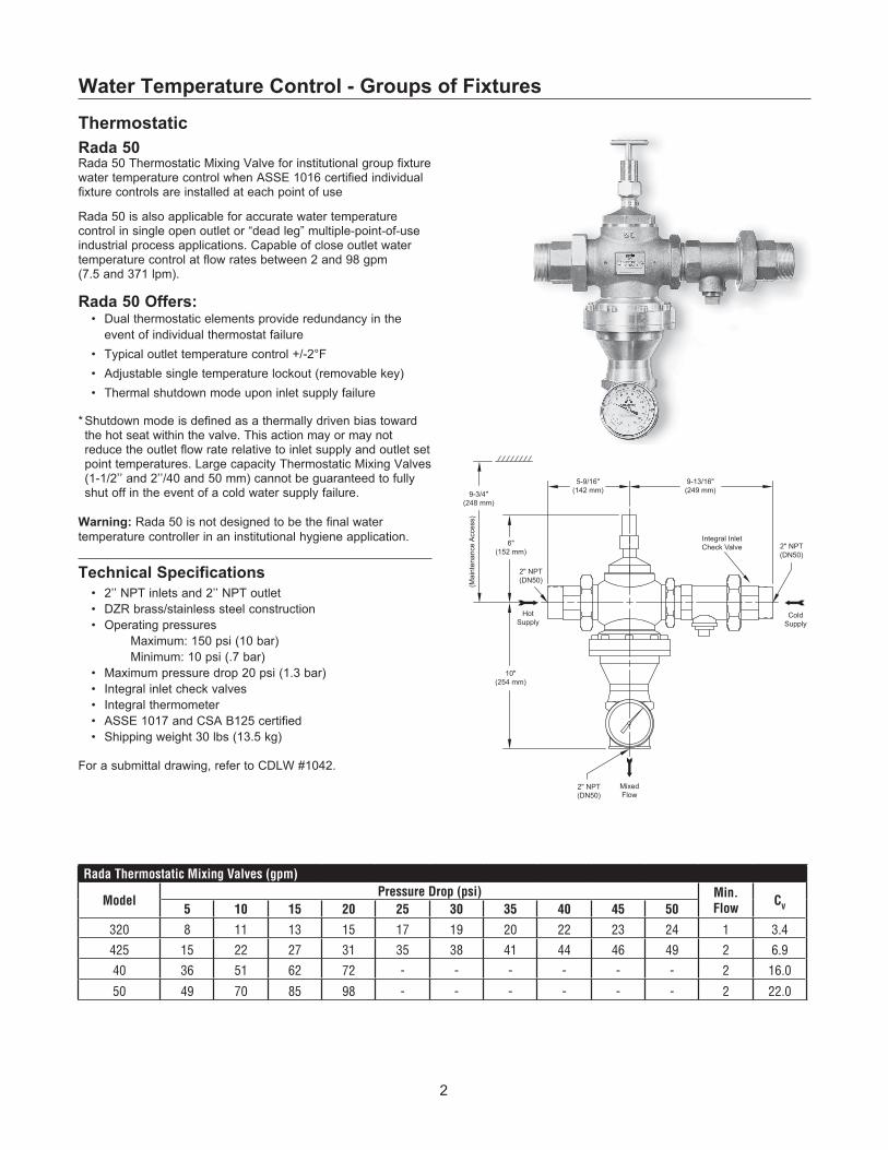
Technical Specifications • 2’’ NPT inlets and 2’’ NPT outlet• DZR brass/stainless steel construction • Operating pressures
Maximum: 150 psi (10 bar) Minimum: 10 psi (.7 bar)
• Maximum pressure drop 20 psi (1.3 bar)• Integral inlet check valves• Integral thermometer• ASSE 1017 and CSA B125 certified• Shipping weight 30 lbs (13.5 kg)
For a submittal drawing, refer to CDLW #1042.
9-13/16"(249 mm)9-3/4"
(248 mm)
6"(152 mm)
2" NPT(DN50)
HotSupply
10"(254 mm)
(Mai
nten
ance
Acc
ess)
ColdSupply
MixedFlow
2" NPT(DN50)
2" NPT(DN50)
5-9/16"(142 mm)
Integral InletCheck Valve
Rada Thermostatic Mixing Valves (gpm)
ModelPressure Drop (psi) Min.
FlowCV5 10 15 20 25 30 35 40 45 50
320 8 11 13 15 17 19 20 22 23 24 1 3.4
425 15 22 27 31 35 38 41 44 46 49 2 6.9
40 36 51 62 72 - - - - - - 2 16.0
50 49 70 85 98 - - - - - - 2 22.0
3
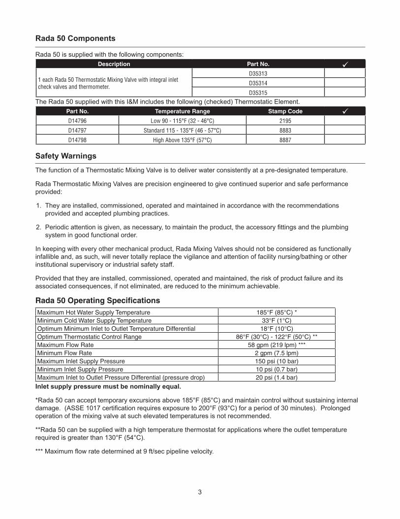
Rada 50 Components
Rada 50 is supplied with the following components:
The Rada 50 supplied with this I&M includes the following (checked) Thermostatic Element.
Safety Warnings
The function of a Thermostatic Mixing Valve is to deliver water consistently at a pre-designated temperature.
Rada Thermostatic Mixing Valves are precision engineered to give continued superior and safe performance provided:
1. They are installed, commissioned, operated and maintained in accordance with the recommendations provided and accepted plumbing practices.
2. Periodic attention is given, as necessary, to maintain the product, the accessory fittings and the plumbing system in good functional order.
In keeping with every other mechanical product, Rada Mixing Valves should not be considered as functionally infallible and, as such, will never totally replace the vigilance and attention of facility nursing/bathing or other institutional supervisory or industrial safety staff.
Provided that they are installed, commissioned, operated and maintained, the risk of product failure and its associated consequences, if not eliminated, are reduced to the minimum achievable.
Inlet supply pressure must be nominally equal.
*Rada 50 can accept temporary excursions above 185°F (85°C) and maintain control without sustaining internal damage. (ASSE 1017 certification requires exposure to 200°F (93°C) for a period of 30 minutes). Prolonged operation of the mixing valve at such elevated temperatures is not recommended.
**Rada 50 can be supplied with a high temperature thermostat for applications where the outlet temperature required is greater than 130°F (54°C).
*** Maximum flow rate determined at 9 ft/sec pipeline velocity.
Rada 50 Operating Specifications
Part No. Temperature Range Stamp Code
D14796 Low 90 - 115°F (32 - 46°C) 2195
D14797 Standard 115 - 135°F (46 - 57°C) 8883
D14798 High Above 135°F (57°C) 8887
Description Part No.
1 each Rada 50 Thermostatic Mixing Valve with integral inlet check valves and thermometer.
D35313
D35314
D35315
Maximum Hot Water Supply Temperature 185°F (85°C) *Minimum Cold Water Supply Temperature 33°F (1°C) Optimum Minimum Inlet to Outlet Temperature Differential 18°F (10°C)Optimum Thermostatic Control Range 86°F (30°C) - 122°F (50°C) **Maximum Flow Rate 58 gpm (219 lpm) ***Minimum Flow Rate 2 gpm (7.5 lpm)Maximum Inlet Supply Pressure 150 psi (10 bar)Minimum Inlet Supply Pressure 10 psi (0.7 bar)Maximum Inlet to Outlet Pressure Differential (pressure drop) 20 psi (1.4 bar)

4
The Rada 50 Thermostatic Mixing Valve must be installed as per the piping schematic provided below. Failure to follow this directive will compromise valve/system performance, void all warranties and may create a user comfort issue and safety concern.
Armstrong has Rada technical support personnel available from 8:00 a.m. to 5:00 p.m. EST. Call Toll Free 1-888-HOT HOSE.
Notes:1. Rada 50 may be installed in a vertical or horizontal position.
2. Rada 50 must be installed in a standard HOT-LEFT/COLD-RIGHT inlet supply configuration. There are red (hot) and blue (cold) markings on each valve. The inlet supplies must always match the corresponding inlet ports on the valve.
3. Be sure to thoroughly flush the pipework before fitting the Rada 50. A good quality “Y” type strainer (40 mesh minimum) should be installed on hot and cold water inlets to mixing valve.
4. Be sure to “make up” all “sweat” or “soldered” fittings ahead of time. Do not expose Rada 50 or any of its fittings to extreme temperatures (such as an acetylene or propane torch).
5. Rada 50 is pre-set at the factory to a fixed outlet temperature. It is highly unlikely that the installation site conditions will match the test conditions. As such:
RADA 50 MUST BE PRE-SET ON SITE BY QUALIFIED PERSONNEL. Rada 50 set up (commissioning) protocol is included on page 5.
6. Rada 50 requires service access beneath the bonnet assembly. A minimum access clearance of 18” is suggested.
Rada 50 Piping Schematic
Rada 50 Installation
Hot Water Supply
Cold Water Supply
Mixed Flow50
High Importance:Install "Y" Strainers on each Inlet Supply

5
Commissioning must be carried out in accordance with these instructions, and must be conducted by designated, qualified and competent personnel.
Ensure that the hot and cold supplies are at their designated pressures and temperatures. Open mixed water outlet and wait until the hot and cold inlet temperatures are stable. Note the mixed water temperature.
If the mixed water temperature requires adjustment, turn the adjusting key clockwise (Photo 5-1) to reduce the temperature or counterclockwise to increase the temperature. Turn the key only 1/2 turn at a time and allow a few seconds for the temperature to stabilize.
Fixed Temperature Setting
Remove and store the key.Rada 50 is supplied with a removable temperature adjustment key. The temperature adjustment spindle is protected by a lock shield mechanism to discourage unauthorized adjustment.
Commissioning the Rada 50
Rada 50 Thermostatic Mixing Valves should be inspected annually, or more frequently where acknowledged site conditions such as high mineral content water dictate.
To service the Rada 50 proceed as follows:
Isolate/by-pass the valve by turning off each inlet supply.Isolate the outlet.
Step 1. Turn the adjustment screw, using the Temperature Adjustment key (Part No. D18462) provided, counter clockwise until it comes to a stop. To make resetting easier after service, count the number of turns to full stop and note them in the box provided. Refer to Photo 5-2.
Step 2.Remove the Bonnet Assembly (Part No. D33741) with a large wrench by turning counterclockwise. Refer to Photo 5-3.
Rada 50 Servicing and Maintenance
Photo 5-1
Adjustment screw turns
Photo 5-2
Photo 5-3

6
A. Turn the Adjustment Screw fully clockwise and remove it from the Bonnet Assembly. Refer to Photo 6-1.
B. Remove the Adjustment O-Seals (3) and Cover O-Seal (Service/O-Seal Kit Part No. D33467).
C. Clean and inspect the Cold Valve Face along with all the other machined surfaces using a scouring cloth or a domestic pot cleaner.
D. Reinstall O-Seals into Bonnet Assembly after first applying a silicone-based lubricant such as Dow 111 and re-install adjustment screw.
Rada 50 Servicing and Maintenance
Step 3. Fit the Cartridge Removal Tool (Part No. D18463) into the two tappings on the face of the Cartridge Assembly (Part No. D33431 / D33432 / D33433). Refer to Photo 6-2.
Step 4. Gently withdraw the Cartridge Assembly, the Return Spring and Spring Support Washer. Refer to Photo 6-3.
Step 5. Remove Slide Valve Seal (the slide valve seal consists of a white teflon and black EPDM seal) from the Valve Body; clean seal groove, replace Slide Valve Seal after first applying a silicone based lubricant such as Dow 111. Refer to Drawing 1 Page 8.
Step 6. Using two wrenches, grip the hex at each end of the Cartridge Assembly and carefully unscrew and remove whichever end piece comes loose first. Refer to Drawing 2 Page 8.
Step 7. Remove the Thermostatic Element (Part No. D14796 / D14797 / D14798).Refer to Photo 6-4.
Bonnet Assembly Part No. D33741
Bonnet Assembly Servicing:Refer to Drawing 1 Page 11
Photo 6-1
Photo 6-2
Photo 6-3
Photo 6-4

7
Rada 50 Servicing and Maintenance
Step 8. Using a screwdriver placed through the cartridge body to “hold back” carefully unscrew the remaining end cap on the Cartridge Assembly.Refer to Photo 7-1.
Step 9. Clean the Slide Valve using a scouring cloth or a domestic pot cleaner but do not attempt to remove the slide valve from the spool. Refer to Drawing 2 Page 8.
Do not use the scouring cloth on the spool, you will scratch the specially coated surface. Use a soft cloth and water.
Step 10.Ensure that the inner surfaces of the Element Guide, Spool and Spool End cap are clean.
Step 11.Replace Push Rod Seal (Service/O-Seal Kit Part No. D33467) on Push Rod within Element Guide and reassemble. Refer to Drawing 2 Page 8.
Step 12.Reinstall Element Guide into Cartridge Body being careful to locate the Element Guide at the end of the cartridge, which houses the slide valve. Do not over torque. Refer to Drawing 2 Page 8.
Step 13.Replace Thermostatic Element after first applying a silicone-based lubricant such as Dow 111 to the pistons at either end. The Thermostatic Element comprises two thermostats joined by a spring. Insert the complete assembly so that the thermostat with the flange (baffle plate) locates first. Refer to Photo 7-2.
Step 14.Replace the Spool Endcap using care not to over torque. Refer to Drawing 2 Page 8.
Step 15.
Replace slide valve seal (slide valve consists of a white Teflon® and black EPDM seal).Note: Always use new seals (Service/O-Seal Kit Part No. D33467).
Step 16. Reinstall the Spring Support Washer and Return Spring. Refer to Drawing 1 Page 8.
Step 17. Reinstall the Cartridge Assembly into the Valve Body.
Step 18. Replace Bonnet Assembly with the adjustment screw turned fully counter-clockwise.
Step 19. Refer to your reminder on Page 5, Step 1, and return adjustment screw to its original set point. Pressure test and re-commission the Valve following the directions on Page 5.
flange (baffle plate)
Photo 7-2
Photo 7-1

8
Rada 50
Drawing 1
Adjusting Screw
Valve Cover
Cold Valve Face
Cover Seal
Cartridge Removal Tool(Part No. D18463)
Cartridge See Page 12
Spring Support Washer
Return Spring
Slide Valve Seal
Spool Support Ring
Cold InletHot Inlet
Adjustment Seals (3)
Hot Valve Face
Indicates sealing surfaces which must be clean, smooth and undamaged.
Drawing 2

9
18
19
20
21
22
23
24
25
26
27
28
29
30
1
2
3
4
5
6
910
11
12
13
14
15
16
17
Cold InletHot Inlet
Cartridge D
etail
78
31
Rada 50 Parts List
Bonnet AssemblyPart No. D33741
Cartridge Assembly Part No. D33431
D33432 D33433
Ref. No.
Part Name
Assembly Name
Part No.
List Price
1 Adjusting Screw
Bonnet Assembly D33741
Consult Factory
2 Lockshield Nut*3 Adjustment Seal (3)4 Valve Cover*5 Cover Seal6 Return Spring — D184627 Valve Body — D33485
*8 Coupling Seal Service/ O-Seal Pack D33467
*9 Slide-Valve Seal11 Flange Bolt (8) Screw Pack D33435
*12 Flange Seal Service/ O-Seal Pack D33467
13 Keeper Plate — D3348614 By-Pass Valve (6) — D3346415 By-Pass Plate — D33487
*16 Spool Support Ring Service/ O-Seal Pack D33467
17 Outlet Body — D33488
Ref. No.
Part Name
Assembly Name
Part No.
List Price
18 Push Rod
Cartridge Assembly D33469
Consult Factory
19 Element Guide
20 Over-Heat Spring
21 Slide-Valve
*22 Push Rod Seal
23 Slide Valve Retainer
*24 Spring Support Washer
25 Baffle Plate Retainer
26 Baffle Plate
27 Spool
28 “Thermostat Element (2)”
29 Element Support Spring
30 Spool End Cap
31 Inlet Check Valve Inlet CV Kit (2) D33472*Available in Service/O-Seal Pack D33467
† Also included with Thermostat Assembly Part No. D14796D14797D14798

10
Rada 50/50R Common Spare Parts
Part No. Description System Temp. Range
D18462 Temperature Adjustment Key —
D18463 Cartridge Removal Tool —
D33467 Service/O-Seal Kit —
D14796 Thermostatic Element Low Temp. 90 - 114°F
D14797 Thermostatic Element Standard 115 - 135°F
D14798 Thermostatic Element High Temp. Above 136°F
D33468 Cartridge Assembly Low Temp. 90 - 125°F
D33469 Cartridge Assembly Standard 113 - 143°F
D33470 Cartridge Assembly High Temp. above 136°F
D33741 Model 50 Bonnet Assembly —
D33435 Screw Pack Model 40 and 50 (6) Item 11 —
D33472 Inlet Check Valve Kit (2 each) —
D8931 Outlet Thermometer —

11
Fault Diagnosis
Symptom Cause / Action
1. Mixed Water Temperature too high when mixed water is being used.
a. Temperature setting too high. Temperature has been set when hot supply temperature is too low. Re-adjust temperature setting. See Servicing and Maintenance beginning on Page 5.
b. Hot water has migrated into cold water supply. Close all mixed water outlets and check that cold supply pipework remains cold.
c. Thermostat element has failed. Replace thermostat element. See Servicing and Maintenance beginning on Page 5.
2. Only hot or cold water from outlet.
a. Inlet supplies reversed (i.e. hot supply to cold inlet). Check - Rectify.
b. Not hot water reaching mixing valve. Check.
c. Check strainers and inlet fittings for blockage.
d. Refer to symptom 6 below.
e. Installation conditions continuously outside operating parameters:
3. Fluctuating or reduced flow rate
Normal function of mixing valve when operating conditions are unsatisfactory.
a. Check strainers and inlet/outlet fittings for flow restriction.
b. Ensure that minimum flow rate is sufficient for supply conditions.
c. Ensure that dynamic inlet pressures are nominally balanced.
d. Ensure that inlet temperature differentials are sufficient.
e. (Subject to rectification of supply conditions) Check thermostatic performance; renew cartridge assembly if necessary.
4. No flow from mixing valve outlet
Check inlet isolators are fully open.
a. Check strainers and inlet/outlet fittings for blockage.
b. Hot or cold supply failure; thermostat holding correct shutdown function. Rectify.
5. Blend temperature drift
Indicated operating conditions changed.
a. Refer to problem 3 above.
b. Hot supply temperature fluctuation (rectify and refer to Commissioning Page 5).
c. Supply pressure fluctuation. Check - Rectify.
6. Hot water in cold supply or cold water in hot supply Indicates check valves require maintenance.
7. Water leaking from valve bodySeal(s) worn or damaged.
a. Obtain Service Pack, and replace all seals.
8. Mixed water temperature varies, and does not respond to adjustment.
a. The “Cartridge” has seized in the Thermostatic Mixing Valve. Carry out a full service. See Servicing and Maintenance beginning on Page 5.
b. The “Thermostat Element” has failed. Replace Thermostat Element. See Servicing and Maintenance beginning on Page 5.
9. Mixed water flow rate is reduced.
a. Partly blocked strainers. Check - Clean/Replace
b. Supply pressure has fallen. Check system at incoming main and other accessible point downstream.
c. Extra demand has been added to the system. Check maximum flow-rate for the “Mixing Valve” against maximum expected flow-rate. See Page 3.
10. Mixed water temperature suddenly runs cold.
a. Maximum allowable flow-rate has been exceeded. See Page 3. Fit auxiliary mixing valve in parallel or reduce the system demand.

12
Armstrong International221 Armstrong Blvd., Three Rivers, Michigan 49093 - USAPh: (269) 279-3602 Toll Free: (888) HOT-HOSE (468-4673) Fax: (269) 279-3130
ALIB-50-BRada 50
Printed in U.S.A. - 5/12© 2012 Armstrong International, Inc.
Designs, materials, weights and performance ratings are approximate and subject to change without notice.Visit armstronginternational.com for up-to-date information.
Limited Warranty and RemedyArmstrong Hot Water Group, Inc. (“Armstrong”) warrants to the original user of those products supplied by it and used in the service and in the manner for which they are intended, that such products shall be free from defects in material and workmanship for a period of one (1) year from the date of installation, but not longer than 15 months from the date of shipment from the factory [unless a Special Warranty Period applies, as listed below]. This warranty does not extend to any product that has been subject to misuse, neglect, or alteration after shipment from the Armstrong factory. Except as may be expressly provided in a written agreement between Armstrong and the user, which is signed by both parties, Armstrong DOES NOT MAKE ANY OTHER REPRESENTATIONS OR WARRANTIES, EXPRESS OR IMPLIED, INCLUDING, BUT NOT LIMITED TO, ANY IMPLIED WARRANTY OF MERCHANTABILITY OR ANY IMPLIED WARRANTY OF FITNESS FOR A PARTICULAR PURPOSE. The sole and exclusive remedy with respect to the above limited warranty or with respect to any other claim relating to the products or to defects or any condition or use of the products supplied by Armstrong, however caused, and whether such claim is based upon warranty, contract, negligence, strict liability, or any other basis or theory, is limited to Armstrong’s repair or replacement of the part or product, excluding any labor or any other cost to remove or install said part or product, or, at Armstrong’s option, to repayment of the purchase price. As a condition of enforcing any rights or remedies relating to Armstrong products, notice of any warranty or other claim relating to the products must be given in writing to Armstrong: (i) within 30 days of last day of the applicable warranty period, or (ii) within 30 days of the date of the manifestation of the condition or occurrence giving rise to the claim, whichever is earlier. IN NO EVENT SHALL ARMSTRONG BE LIABLE FOR SPECIAL, DIRECT, INDIRECT, INCIDENTAL OR CONSEQUENTIAL DAMAGES, INCLUDING, BUT NOT LIMITED TO, LOSS OF USE OR PROFITS OR INTERRUPTION OF BUSINESS. The Limited Warranty and Remedy terms herein apply notwithstanding any contrary terms in any purchase order or form submitted or issued by any user, purchaser, or third party and all such contrary terms shall be deemed rejected by Armstrong.
Special Warranty Periods are as follows:
Flo-Direct Gas Fired Water HeaterThe stainless steel structure and stainless steel internals (flame, tube, pall rings, supports, etc.) shall have a ten (10) year non-prorated guarantee against burn out or any structural failure caused by materials and workmanship. Provided only clean potable water is heated. The other components on the Flo-Direct, such as valves, combustion equipment, electrical controls, and the burner shall have a two (2) year non-prorated guarantee against failure caused by materials and workmanship.
Flo-Rite-Temp Instantaneous Water HeaterThe tube bundle shall have a 10-year guarantee against failure caused by materials or workmanship provided by Armstrong but not against gasket failure or damage caused by corrosion, water hammer or lack of proper cleaning.
Flo-Rite-Temp Packaged Instantaneous Water HeaterTwo (2) years from the date of installation, but not longer than 27 months from the date of shipment. See above for tube bundle guarantee.
Flo-Eco High Efficiency Gas Water HeaterThe heat exchanger and supplied integral components such as the burner, the electrical controls and valving shall have a two (2) year warranty from the date of installation but no longer than 27 months from the date of shipment. The tank and replaceable tank liner shall have a 5 year warranty from the date of shipment.
The Brain – Model DRV80 and derivative assemblies shall have a 5-year all component parts warranty.