rac 3 main spindle drive controller - bosch rexroth · pdf filefigure 1.1: the rac 3 main...
TRANSCRIPT
RAC 3Main Spindle Drive Controller
DOK-DIAX01-RAC03******-PRJ1-EN-P
Project Planning Manual
mannesmannRexroth
engineering
Indramat258780
2 • DOK-DIAX01-RAC03******-PRJ1-DE-E1,44• 07.97
About this documentation
Main Spindle Drive Controller RAC 3
Planning and Design
DOK-DIAX01-RAC03******-PRJ1-EN-E1,44
• 209-0042-4116-00
This electronic document is based on the hardcopy document with documentdesig.: 209-0042-4116-00 EN/03.94
This documentation serves
– to introduce the drive controller
– to mechanically integrate the drive controller into the control cabinet
– to assist in assembly and installation
– to describe the AS programming module
– to explain the hardware delivered and its best storage conditions
The supplementary technical documentation is used
– during commissioning, operation and servicing
– to electrically integrate the drive controller into the control cabinet
The „documentation summary“ offers an overview of all technical documen-tation of the main spindle drive and contents.
The „supplementary documentation“ summary lists all titles and their ordernumbers.
Titel
Type of documentation:
Documenttype
Internal file reference
Reference
This documentationis used:
© INDRAMAT GmbH, 1994Copying of this document, and giving it to others and the use or communicationof the contents thereof, are forbidden without express authority. Offenders areliable to the payment of damages.All rights are reserved in the event of the grant of a patent or the registrationof a utility model or design. (DIN 34-1)
The electronic documentation (E-doc) may be copied as often as needed ifsuch are to be used by the consumer for the purpose intended.
All rights reserved with respect to the content of this documentation and theavailability of the products.
INDRAMAT GmbH • Bgm.-Dr.-Nebel-Straße 2 • D-97816 LohrTelefon 0 93 52 / 40-0 • Tx 689421 • Fax 0 93 52 / 40-48 85
Dept ENA (MR, FS)
Copyright
Validity
Publisher
Designation of documentation Release- Comentsup to present edition date
209-0042-4116-00 EN/03.94 Mar./94 First Edition
DOK-DIAX01-RAC03******-PRJ1-EN-E1,44 Jul./97 First E-Dok
Change procedures
Function of the supple-mentary documenta-
tion
3 • DOK-DIAX01-RAC03******-PRJ1-DE-E1,44• 07.97
Table of contents
1. The RAC 3 main spindle drive controller 5
2. Control Cabinet Construction 11
2.1. Environmental conditions ............................................................... 11
2.2. Mechanical data .............................................................................14
2.3. Thermal data ..................................................................................20
2.3.1. Guidelines on the use of cooling devices in
control cabinets ..............................................................................22
2.4. Electrical data .................................................................................24
2.5. Summary of technical data ............................................................31
2.6. Type codes .....................................................................................32
3. AS programming module 33
3.1. Types of AS programming modules ...............................................34
3.2. The compatibility of AS programming modules ............................34
3.3. Rating plate information .................................................................35
3.4. Type codes .....................................................................................36
4. Condition upon delivery 37
5. Identifying the merchandise 38
6. Storage and transportation 41
7. Assembly 42
7.1. Installing the drive controller in the control cabinet ........................44
8. Installation guidelines 45
Table of contents

4 • DOK-DIAX01-RAC03******-PRJ1-DE-E1,44• 07.97
9. Commissioning guidelines 46
10. Servicing guidelines 47
10.1. Fault diagnosis ...............................................................................47
10.2. Defective controller .........................................................................47
11. Index 49
12. Supplementary documentation 52
Table of contents
5 • DOK-DIAX01-RAC03******-PRJ1-DE-E1,44• 07.97
1. The RAC 3 main spindle drive controller
1. The RAC 3 main spindle drive controller
RAC3.tif
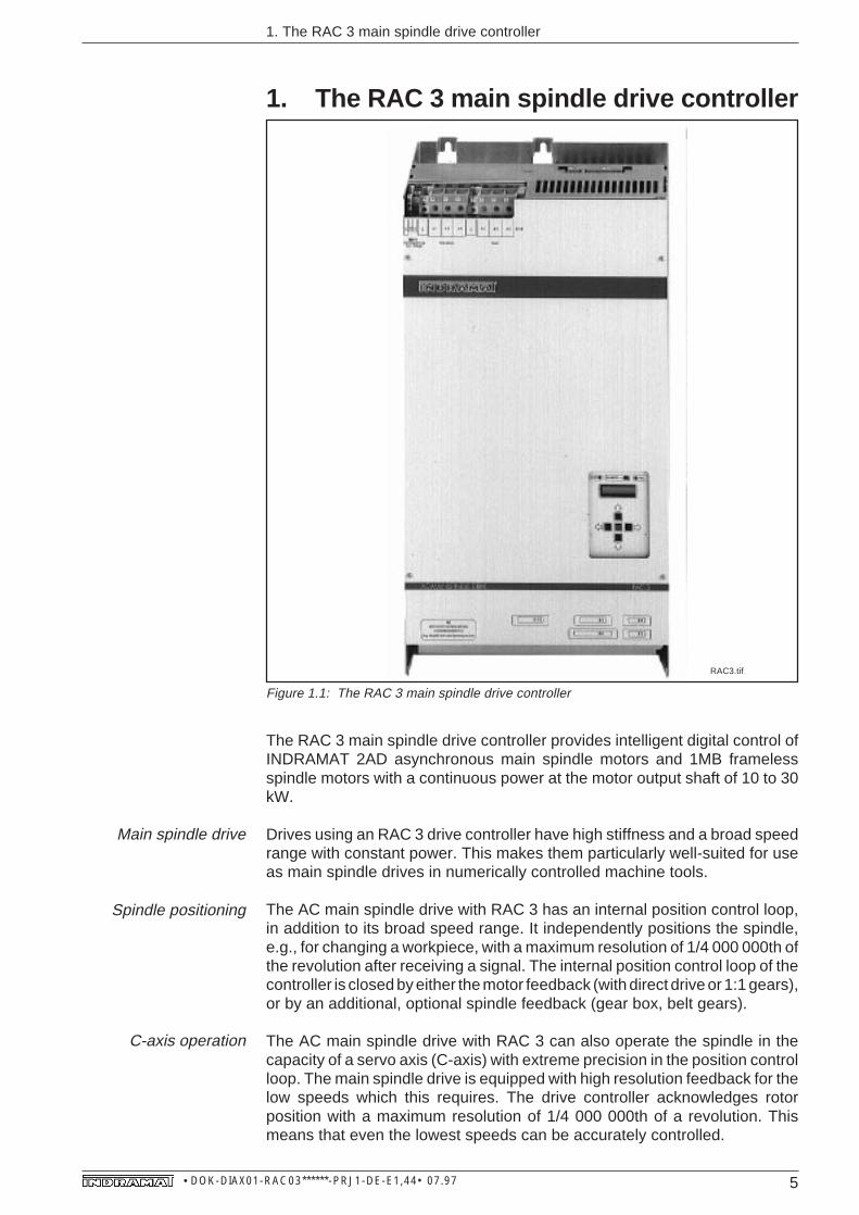
Figure 1.1: The RAC 3 main spindle drive controller
The RAC 3 main spindle drive controller provides intelligent digital control ofINDRAMAT 2AD asynchronous main spindle motors and 1MB framelessspindle motors with a continuous power at the motor output shaft of 10 to 30kW.
Drives using an RAC 3 drive controller have high stiffness and a broad speedrange with constant power. This makes them particularly well-suited for useas main spindle drives in numerically controlled machine tools.
The AC main spindle drive with RAC 3 has an internal position control loop,in addition to its broad speed range. It independently positions the spindle,e.g., for changing a workpiece, with a maximum resolution of 1/4 000 000th ofthe revolution after receiving a signal. The internal position control loop of thecontroller is closed by either the motor feedback (with direct drive or 1:1 gears),or by an additional, optional spindle feedback (gear box, belt gears).
The AC main spindle drive with RAC 3 can also operate the spindle in thecapacity of a servo axis (C-axis) with extreme precision in the position controlloop. The main spindle drive is equipped with high resolution feedback for thelow speeds which this requires. The drive controller acknowledges rotorposition with a maximum resolution of 1/4 000 000th of a revolution. Thismeans that even the lowest speeds can be accurately controlled.
Main spindle drive
Spindle positioning
C-axis operation

6 • DOK-DIAX01-RAC03******-PRJ1-DE-E1,44• 07.97
1. The RAC 3 main spindle drive controller
Drive controller fordirect connection to
the mains
Cooling
Cooling with air insidethe control cabinet
Cooling with airoutside the control
cabinet
ILK+ALK/RAC3
Air exit
Air entrance
Cooling withair inside the control cabinet
Cooling withair outside the control cabinet
Air exit
Air entrance
Back wall of control cabinet or mounting plate
withoutslits
Back wall of control cabinet or mounting plate
withslits
Figure 1.2: Possible cooling methods for the RAC 3
The RAC 3 can be directly connected to a three-phase supply network with 3x AC 380 volts ... 460 volts, +/- 10%, 50 ... 60 Hz. Both mains contactor andemergency-stop circuits are integrated. The energy recovered during brakingis fed back into the three-phase supply network. This also occurs in anemergency stop. In the event of mains failure, the drive with RAC 3 can bringthe main spindle to rest, if the RAC3 is equipped with the additional, optionalbleeder.
The heatsink for both the power electronics and fan is built into the housingof the RAC main spindle drive controllers. The cooling air is fed through an airshaft within the unit.
The RAC drive controllers can be cooled using air from inside or outside thecontrol cabinet. Every RAC offers either option. Any required structuralchanges are simple and can be performed without accessories.
The cooling air flow is drawn in and blown out within the control cabinet.
The cooling air is drawn in from outside the control cabinet through slits in theback wall of the cabinet, and then blown out. Heat from energy loss is fed intothe outside air of the control cabinet.
7 • DOK-DIAX01-RAC03******-PRJ1-DE-E1,44• 07.97
1. The RAC 3 main spindle drive controller
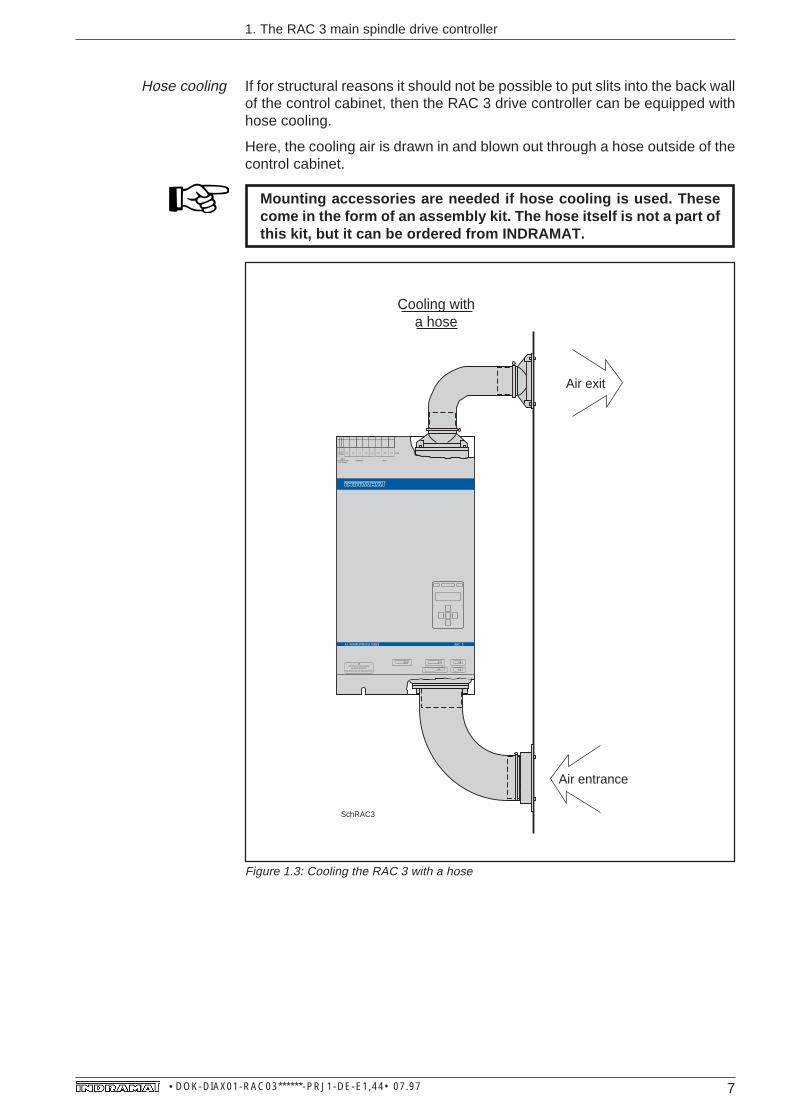
Hose cooling If for structural reasons it should not be possible to put slits into the back wallof the control cabinet, then the RAC 3 drive controller can be equipped withhose cooling.
Here, the cooling air is drawn in and blown out through a hose outside of thecontrol cabinet.
Mounting accessories are needed if hose cooling is used. Thesecome in the form of an assembly kit. The hose itself is not a part ofthis kit, but it can be ordered from INDRAMAT.
SchRAC3
Cooling witha hose
X 14
220 VSteuerspannung
Aux. VoltageNetz/Mains
L 3L 2L 1LN
Motor
A 3A 1 A 2
X 4
X 2Prog. Modul AS nicht unter Spannung wechseln
X 3
X 5X 1 3AS
SWITCH OFF VOLTAGE BEFORECHANGING MODULE AS
AC-MAINSPINDLE DRIVE RAC 3
Air exit
Air entrance
Figure 1.3: Cooling the RAC 3 with a hose

8 • DOK-DIAX01-RAC03******-PRJ1-DE-E1,44• 07.97
motor NTC connectionmotor power connectiondirect mains connectioninterface for monitoring and controlfeedback interfaceinterface for CNC controlcontrol voltage connectionadditional interfaces
1. The RAC 3 main spindle drive controller
BedienfeldNetzdirektanschlußProgrammiermodulMotorheißleiteranschlußMotorleistungsanschlußSchnittstelle f. Überwachung u. SteuerschaltungSchnittstellen zur FeedbackSchnittstellen zur NC-SteuerungSteuerspannungsanschlußZusatzschnittstelle
BegriffeRAC3
1 2 3 1 2 3 4 5 6 7 8 9 10
Feedback interfaces:
• motor feedback interface (X3)
• additional encoder input for
spindle feedback or
2nd motor feedback (X5, optional)
• synchronous input for master
spindle feedback (X5a, optional)
CNC controller interfaces:
• controller input, monitor and
analogue outputs
(X2,standard interface)
• speed set-point (X4)
- analogue ± 10 volts (optional)
- digital 16 bit parallel (optional)
- SERCOS interface (optional)
Additional interface (X13, optional)
- digital position set-point,
16 bit parallel
- incremental encoder output
- RS 232 serial interface
Control panel
Motorpower
interface
Direct mainsinterface
Programming module
MotorNTC-resistor
interface
Interface formonitor and
control circuits
X13
X2
X4 X5a X5
X3
X 14
220 VSteuerspannung
Aux. VoltageNetz/Mains
L 3L 2L 1LN
Motor
A 3A 1 A 2
X 4
X 2Prog. Modul AS nicht unter Spannung wechseln
X 3
X 5X 1 3AS
SWITCH OFF VOLTAGE BEFORECHANGING MODULE AS
AC-MAINSPINDLE DRIVE RAC 3
Control voltage
interface
Motor: 2AD 132 D- ..... -AS.3Contr.: RAC 3.1-150-460-...Software: RAC3 1V0.1Parameter: 01.07.93
Serien-Nr.:
INDRAMAT AS 61/006-000
Figure 1.4: Allocation of terms on the RAC 3
9 • DOK-DIAX01-RAC03******-PRJ1-DE-E1,44• 07.97
1. The RAC 3 main spindle drive controller
Programming module The individual parameters needed for the plant and application are pro-grammed at the time of commissioning on site with the keypad on the controlpanel.These parameter values are stored, along with the matching motorparameter values, on the plugged-in programming module.
Should servicing become necessary, then only the controller need be ex-changed. The same programming module is used in the new controller. Thedrive parameters are stored on the programming module and are immediatelyavailable for use.
The drive controllers are available with different speed set-point interfaces:
• analogue speed set-point+/- 10 volts for connection to conventional CNC controls,
• digital speed set-point16 bit parallel for connection to PLCs, advantageous with long line distancesand low set-points,
• SERCOS interfacefor real time communication with the CNC controls of speed, position andtorque set-points and actual values including parameter handling.
An additional encoder input is available for connecting a spindle feedback tothe internal position controller. Additional encoder and synchronization input(master spindle feedback connection) are available for spindle synchroniza-tion.
The RAC 3 drive controller also offers an additional, optional interface whichis available in the form of
• an incremental encoder outputfor position control by the CNC control with C-axis operation or screwing,tapping,
• a serial interfacefor storing and loading parameter values with a PC,
• input for digital position set-point16 bit parallel, for 3,600 positions which can be selected with the use of aPLC.
Interface options
Speed set-point
Additional encoder andsynchronous input
Additional interface

10 • DOK-DIAX01-RAC03******-PRJ1-DE-E1,44• 07.97
main spindle motormotor feedback cablemotor power cablemotor fan cablemains connection cable
1. The RAC 3 main spindle drive controller
X 14
220 VSteuerspannung
Aux. Voltage
Netz/Mains
L3
L2
L1
LN
Motor
A3
A1 A2
X 4
X 2
Prog. Modul AS nicht unter Spannung wechseln
X 3
X 5
X 1 3
AS
SWITCH OFF VOLTAGE BEFORE
CHANGING MODULE AS
AC-MAINSPINDLE DRIVE RAC 3
EinzelkRAC3
Programmingmodule
Motor feedback cable
Motor fan cable
Motor power cable
Main spindle motor
Electrical conn. access.
RAC 3.1 drive controller
Mains connection cable
Controlvoltage supply
Figure 1.5: Individual components of a main spindle unit with allocation of terms

11 • DOK-DIAX01-RAC03******-PRJ1-DE-E1,44• 07.97
2. Control Cabinet Construction
2. Control Cabinet Construction
The information for structurally integrating the RAC 3 main spindle drivecontroller is broken down into
• environmental conditions
• mechanical data
• thermal data
• electrical data
• technical data/type codes
2.1. Environmental conditionsThe values listed in the selection data for the main spindle drives are validwithout restriction if the controller is operated within an ambient temperaturerange of +5 to +45 degrees C. Permissible maximum ambient temperature is+55 degrees C. The graph in figure 2.1 depicts the reduction in rated data.
Ambient temperature
100
80
60
40
20
00 10 20 30 40 50 60
Ambient temperature ϑ [°C]
Tem
pera
ture
fact
or [%
]
DGURRAC3
Figure 2.1: Ambient temperature-dependent reduction in drive data

12 • DOK-DIAX01-RAC03******-PRJ1-DE-E1,44• 07.97
2. Control Cabinet Construction
Installation altitude Maximum installation altitude is 1000 meters above sea level. There is a dropin values for rated torque or power as listed in the selection specs for mainspindle installed at higher altitudes. The graph in Figure 2.2 depicts this drop.
100
80
60
40
20
00 1000 2000 3000 4000 5000
Installation altitude above sea level [m]
Alti
tude
fact
or [%
]
DGhRRAC3
Figure 2.2: Altitude-dependent drop in drive data
The maximum ambient humidity is humidity class F, as per DIN 40 040.
This means that the controller can be operated in humidity-endangered areassuch as workshops in cold, moderate and warm and moist climactic regions.The mean relative humidity may not exceed 70% in the most humid month ofthe year! Beware of condensation water!
Protection category is IP 10, as per EN 60 529 (DIN VDE 0470).
This means the controller is protected against penetration by foreign objectsgreater than 50 mm in diameter.
The controller is not protected against
• water and
• deliberate penetration, e.g., by a hand. It does keep larger body surfacesout.
The RAC 3 is manufactured as per DIN VDE 0160, Sections 5.5.1.3 and6.5.1.3 for installation into a control cabinet or closed housing. Sufficient safetymeasures must be taken in the respective control cabinet design. Themeasures taken must correspond to the safety guidelines for a specificapplication. (For industrial equipment, e.g., EN 60204 / DIN VDE 0113,Section 1).
Permissible ambienthumidity
Protection category ofthe RAC controller

13 • DOK-DIAX01-RAC03******-PRJ1-DE-E1,44• 07.97
2. Control Cabinet Construction
Category of protectionfor the control cabinet
The type of protection needed for the control cabinet is not affected if the RACdrive controller is cooled with air inside the control cabinet.
The type of protection needed for the control cabinet is affected if the RACdrive controller is cooled with outside air because the air current is fed throughthe control cabinet over slits in the back wall.
Assembly as per guidelines (Section 7) means that IP 54 is the category ofprotection for the interior of the control cabinet. IP 24 is the protection categoryfor the fan (see Figure 1.2).

14 • DOK-DIAX01-RAC03******-PRJ1-DE-E1,44• 07.97
2. Control Cabinet Construction
2.2. Mechanical data
X 14
220 VSteuerspannung
Aux. VoltageNetz/Mains
L 3L 2L 1LN
Motor
A 3A 1 A 2
X 4
X 2Prog. Modul AS nicht unter Spannung wechseln
X 3
X 5X 1 3AS
SWITCH OFF VOLTAGE BEFORECHANGING MODULE AS
AC-MAINSPINDLE DRIVE RAC 3
M8 in the control cabinet 190 ± 0,5
380
Air exit
Air entrance
210 ± 0,5 8066
8
690
10
300
MBRAC3
The controller may only be operated in the position shown!
Figure 2.3: RAC 3 main spindle drive controller dimensional data
15 • DOK-DIAX01-RAC03******-PRJ1-DE-E1,44• 07.97
2. Control Cabinet Construction
M8
668
-1
210 ±0,5
110
BBRAC3 aus 109-0770-3002-02
M8M8
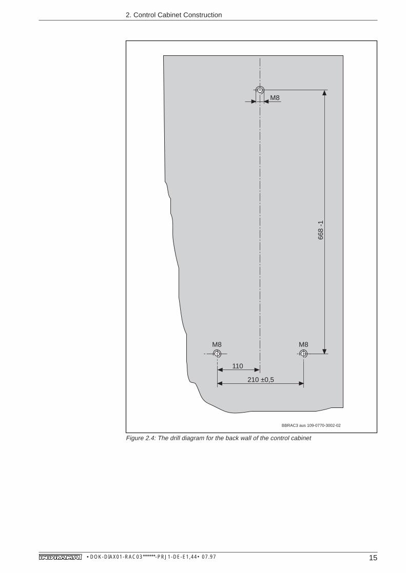
Figure 2.4: The drill diagram for the back wall of the control cabinet

16 • DOK-DIAX01-RAC03******-PRJ1-DE-E1,44• 07.97
2. Control Cabinet Construction
zMALKRAC3 aus 109-0770-3002-02
116 ±0,5 39
M8
68
±0,5
R10
55
96
68
-1
176 ±0,5
15
7 ±
0,5
18
5
210 ±0,5
110
69
R10
View from outside of the control cabinet onto the back wall or mounting panel
80 mmmin.
80min.
Air exit
Air entrance
80 mmmin.
M8M8
Figure 2.5: Additional dimensions for cooling with air outside of the control cabinet

17 • DOK-DIAX01-RAC03******-PRJ1-DE-E1,44• 07.97
2. Control Cabinet Construction
zMILKRAC3
X 14
220 VSteuerspannung
Aux. VoltageNetz/Mains
L 3L 2L 1LN
Motor
A 3A 1 A 2
X 4
X 2Prog. Modul AS nicht unter Spannung wechseln
X 3
X 5X 1 3AS
SWITCH OFF VOLTAGE BEFORECHANGING MODULE AS
AC-MAINSPINDLE DRIVE RAC 3
160 mmmin.
160 mmmin.
Air exit
Air entrance
Figure 2.6: Additional dimensions for cooling with air inside the control cabinet
18 • DOK-DIAX01-RAC03******-PRJ1-DE-E1,44• 07.97
2. Control Cabinet Construction
X 14
220 VSteuerspannung
Aux. VoltageNetz/Mains
L 3L 2L 1LN
Motor
A 3A 1 A 2
X 4
X 2Prog. Modul AS nicht unter Spannung wechseln
X 3
X 5X 1 3AS
SWITCH OFF VOLTAGE BEFORECHANGING MODULE AS
AC-MAINSPINDLE DRIVE RAC 3
Min. bending radius, R=80
Min. bendingradius, R=125
99
35
225
min
.
Air entrance
93,5
63
260
min
. 183
Air exit
zMSchlauch
110
119
71
Air entrance
Air exit
Ø 80 mm
Flange I
Flange III
Ø 125 mm
Flange II
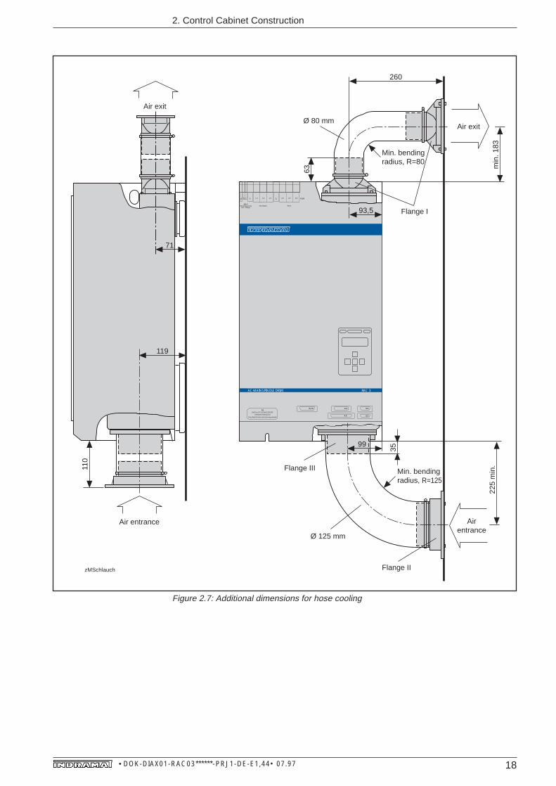
Figure 2.7: Additional dimensions for hose cooling

19 • DOK-DIAX01-RAC03******-PRJ1-DE-E1,44• 07.97
2. Control Cabinet Construction
MBFRAC3
7
165
185
68
35
60 +2
Ø 1
21
Ø 1
25
5
15°
Figure 2.8: Flange II dimensional data for hose cooling
MBStuRAC3
45 ±0,3
Ø 8
0,5
+0,
2
100 ±0,591 +0,5
4,5
(7,9)
146
±0,2
117
±0,1
14,5
79 ±0,1 6
Figure 2.9: Flange I dimensional data for hose cooling

20 • DOK-DIAX01-RAC03******-PRJ1-DE-E1,44• 07.97
2. Control Cabinet Construction
2.3. Thermal dataThe RAC 3 drive controller emits heat during operation over the air slits in thelid of the controller and over the heatsink built into the unit.
Power dissipation
KRRAC3
Internal powerdissipation
Heatsink
PV(ext)
External powerdissipation
max. Pressure Pmax = 160 Pa
min. Air flow Qmin = 300
RAC 3.1
PV(int)
m3
h
Air slits
Air flow
The external and internal power dissipation produced by the RAC 3 drivecontroller is workload dependent. When working out the proportions of thecontrol cabinet or the exhaust air cooling set-up it suffices to know the radiationof heat dependent upon the rated current of the main spindle motor used.
Figure 2.10: Cooling the RAC 3 drive controller
Figure 2.11: Break down of internal and external power dissipation
50 100
0,5
1
Rated motor current in A
Pow
er d
issi
patio
n in
kW
External power dissipationPV(ext)
Internal power dissipationPV(int)
DGVerRAC3

21 • DOK-DIAX01-RAC03******-PRJ1-DE-E1,44• 07.97
The unit can be cooled with air from inside or outside the control cabinet. Thecooling air for the heatsink remains either inside or is drawn in from outside andthen blown out again, depending upon installation method (principle of heatexchange).
The unit is delivered with the inside air cooling method. If a cooling methodusing either outside air or a hose is used, then the unit must be structurallyaltered (see Sec. 7).
The dimensions of the air shaft must be taken into consideration if air is to befed in and out over an air shaft (required air flow!).
If the hose cooling method is used, then the hoses should be kept as short aspossible and should not have more than two bends of 90 degrees per hose.
The values for air flow, Q, and maximum permissible excess pressure, Pmax,should be controlled as a safety measure.
Air shafts and heatsink should be kept clean to avoid overheating!
2. Control Cabinet Construction

22 • DOK-DIAX01-RAC03******-PRJ1-DE-E1,44• 07.97
2. Control Cabinet Construction
2.3.1. Guidelines on the use of cooling devices incontrol cabinets
The RAC 3 drive controller can only be operated up to an ambient temperatureof 45 degrees C.before the drive data begins to drop. It may be necessary touse a cooling device to cool the air inside the control cabinet to maintain theenvironmental conditions.
Dew and condensation water endanger the installed controller if coolingdevices are not properly installed!
Humid air enters the control cabinet and condenses on the controller as it coolsdown!
The condensation water continually formed in cooling devices can drip ontothe controller or be sprayed into the cooling air flow if the cooling device hasnot been properly installed.
• Use only a well-sealed control cabinet if a cooling device is also used so thatmoist and warm air cannot penetrate to form condensation!
• Should a control cabinet be operated while a door is open (upon commis-sioning, during servicing, etc.), then it must be warranted that the controllerat no point in time after closing the door is cooler than the air inside thecontrol cabinet as otherwise condensation could form. The cooling deviceshould continue to run for this reason even when the unit is shutdown, untilthe temperature of the control cabinet air and the installed unit remain at thesame level.
• Cooling devices with fixed temperature settings have to be set at 40 degreesC., no lower!
• Cooling devices with follow-up temperatures should be set so that thetemperature of the air inside the control cabinet is less than 2 degrees C.below the temperature of the outside air. Set temperature limit at 40 degreesC.!
• Always arrange cooling devices so that any condensation water formeddoes not drip onto the installed drive controllers. Cooling devices on the topof a control cabinet necessitate a special control cabinet design (see Fig.2.12)!
• Construct the control cabinet in such a way that the cooling device fancannot blow the condensation water formed during shut downs onto thedrive controller (see Fig. 2.13)!
Danger fromcondensation
Danger fromcondensation water
Proper use ofcooling devices
Avoiding condensation
Avoiding drippingand spraying

23 • DOK-DIAX01-RAC03******-PRJ1-DE-E1,44• 07.97
2. Control Cabinet Construction
Incorrect Correct
Control cabinet
Electronicequipment
warm cold
Cooling device Cooling device
Control cabinet
warm cold
Airshaft
Electronicequipment
KDRAC3
Figure 2.12: Placing the cooling device on the top of the control cabinet
Incorrect Correct
Coolingdevice
Control cabinet
Air entrance
Air exit
Electronic equipment
Control cabinetAir entrance
Coolingdevice
Airshaft
Electronic equipment
KFRAC3
Figure 2.13: Placing the cooling device on the front of the control cabinet
Cooling devices may not drip condensation water onto the installeddrive controller! The correct cooling device temperature must bemaintained!
24 • DOK-DIAX01-RAC03******-PRJ1-DE-E1,44• 07.97
2. Control Cabinet Construction
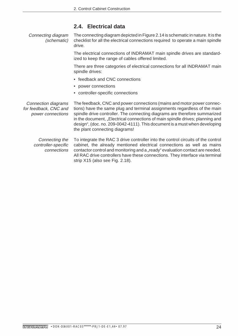
2.4. Electrical dataThe connecting diagram depicted in Figure 2.14 is schematic in nature. It is thechecklist for all the electrical connections required to operate a main spindledrive.
The electrical connections of INDRAMAT main spindle drives are standard-ized to keep the range of cables offered limited.
There are three categories of electrical connections for all INDRAMAT mainspindle drives:
• feedback and CNC connections
• power connections
• controller-specific connections
The feedback, CNC and power connections (mains and motor power connec-tions) have the same plug and terminal assignments regardless of the mainspindle drive controller. The connecting diagrams are therefore summarizedin the document, „Electrical connections of main spindle drives; planning anddesign“, (doc. no. 209-0042-4111). This document is a must when developingthe plant connecting diagrams!
To integrate the RAC 3 drive controller into the control circuits of the controlcabinet, the already mentioned electrical connections as well as mainscontactor control and monitoring and a „ready“ evaluation contact are needed.All RAC drive controllers have these connections. They interface via terminalstrip X15 (also see Fig. 2.18).
Connecting diagram(schematic)
Connection diagramsfor feedback, CNC and
power connections
Connecting thecontroller-specific
connections

25 • DOK-DIAX01-RAC03******-PRJ1-DE-E1,44• 07.97
2. Control Cabinet Construction
BetriebsbereitHauptspindelmotorLeitspindelfeedbackMotorfeedbackanschlußMotorfeedbackMotorheißleiteranschlußMotorleistungsanschlußSpindelfeedbackSteuerein-, MeldeausgängeSynchroneingangZusatzgebereingang
A1
A2
A3
T2
T1
3
2
1X
5
9
X15
X4
X13
X3
Mot
or fe
edba
ckco
nnec
tion
(15
way
, st
anda
rd
inte
rfac
e)
Add
ition
al e
ncod
er
inpu
t (15
way
, op
tiona
l)
X14
Mot
orpo
wer
conn
ectio
n
10
Spe
ed s
et-p
oint
- an
alog
ue (
9 w
ay,
optio
nal)
- di
gita
l (25
way
, opt
iona
l)-
SE
RC
OS
inte
rfac
e (
phot
ocon
duct
or,
optio
nal)
Add
ition
alin
terf
ace
(opt
iona
l)-
digi
tal
pos
ition
set
-poi
nt (
25 w
ay)
- in
crem
enta
l en
code
r o
utpu
t (15
way
)-
seria
l int
erfa
ce (
25 w
ay)
X2
Con
trol
inpu
t, si
gnal
and
an
alog
ue o
utpu
ts
(37
way
, sta
ndar
d in
terf
ace)
DC
24V
, 1A
,fo
r ex
t.us
eN
o. o
f cor
es
corr
espo
nds
to o
ptio
nm
ax. 3
7
No.
of c
ores
corr
espo
nds
to o
ptio
n
CN
C c
ontr
ol
X5a
Syn
chro
nous
inpu
t(1
5 w
ay, o
ptio
nal)
M 3M
otor
feed
back
Spi
ndle
feed
back
Mas
ter
spin
dle
feed
back
Mai
n sp
indl
e m
otor
(or f
ram
eles
s sp
indl
e m
otor
in th
e ca
paci
ty o
f a d
irect
spi
ndle
driv
e)
APRAC3
88
8
Mot
or
NT
C-r
esis
tor
conn
ectio
n
RA
C 3
Driv
e C
ontr
olle
r
+24
V0V
5
6
Bb
Bb
ON
ON
OF
FO
FF
1
23
4
"Rea
dy"
stat
e24
V, 1
AO
FF
ON
Mai
ns c
onta
ctor
con
trol
Mai
nsco
ntac
tor
mon
itorin
g
3 x
AC
380
… 4
60V,
50H
zgr
ound
ed o
r un
grou
nded
mai
ns
L1 L
2 L
3
L1 L2 L3
F1
K17
8
CS
C
S
X16
X14
L N
Con
trol
volta
ge22
0V,
50…
60H
z±1
0%, 2
00V
A
X14
Figure 2.14: Schematic RAC 3 connection diagram
26 • DOK-DIAX01-RAC03******-PRJ1-DE-E1,44• 07.97
2. Control Cabinet Construction
BetriebsbereitGerätelüfterNetzanschlußNetzschützüberwachungskontaktSchaltnetzteil
L1 L2 L3Mains connection
Circuits for signal
voltages
K1K5
K1
M
Internalcontroller fan
A1 A2 A3Motor powerconnection
&
Monitor signal voltage
No faultNo E-stop
K4
X15/1
X15/2
X15/3
ONK1
OFF
X15/4
0VL
24 VL
K1
Bb"ready"
CS mains contactor
monitoring contact
X15/7 X15/8
RAC 3 Drive Controller
SSRAC3X15/5 X15/6
X14
X14
Controlvoltage220V ~
L
N
K5
Safety switchas per VDE (*)
K4
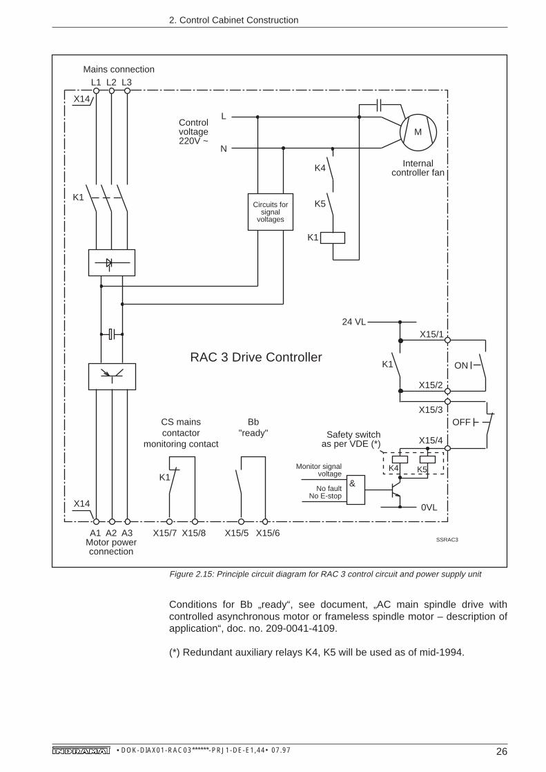
Figure 2.15: Principle circuit diagram for RAC 3 control circuit and power supply unit
Conditions for Bb „ready“, see document, „AC main spindle drive withcontrolled asynchronous motor or frameless spindle motor – description ofapplication“, doc. no. 209-0041-4109.
(*) Redundant auxiliary relays K4, K5 will be used as of mid-1994.

27 • DOK-DIAX01-RAC03******-PRJ1-DE-E1,44• 07.97
Feedback andCNC connections
All feedback and CNC connection interfaces are identical in terminal assign-ment and designation regardless of the main spindle controller. They can befound in the document, „Electrical connections of the main spindle drives“(doc. no. 209-0042-4111), or in „AC main spindle drives with controlledasynchronous motor or frameless spindle motor; description of application“(doc. no. 209-0041-4109).
Both the functions and signal levels linked to these interfaces are also thesame regardless of the main spindle drive controller. They are described in thelatter document.
The electrical connections required are dependent upon
• the functional options of the drive controller selected.
Figure 2.16 outlines how the interfaces of each main spindle controller(standard interfaces) are assigned, with the use of a text string, to thecorresponding connecting diagram. Figure 2.17 depicts the assigning of thefunctional options of the drive controller to the corresponding connectingdiagram with the use of a text string.
Connecting plans for feedback and CNC connections can be quickly locatedin the document entitled, „Electrical connections of the main spindle drive;planning and design“, by using the text string (last column of Figs. 2.16 & 2.17).The index of this document lists these text strings.
2. Control Cabinet Construction
28 • DOK-DIAX01-RAC03******-PRJ1-DE-E1,44• 07.97
2. Control Cabinet Construction
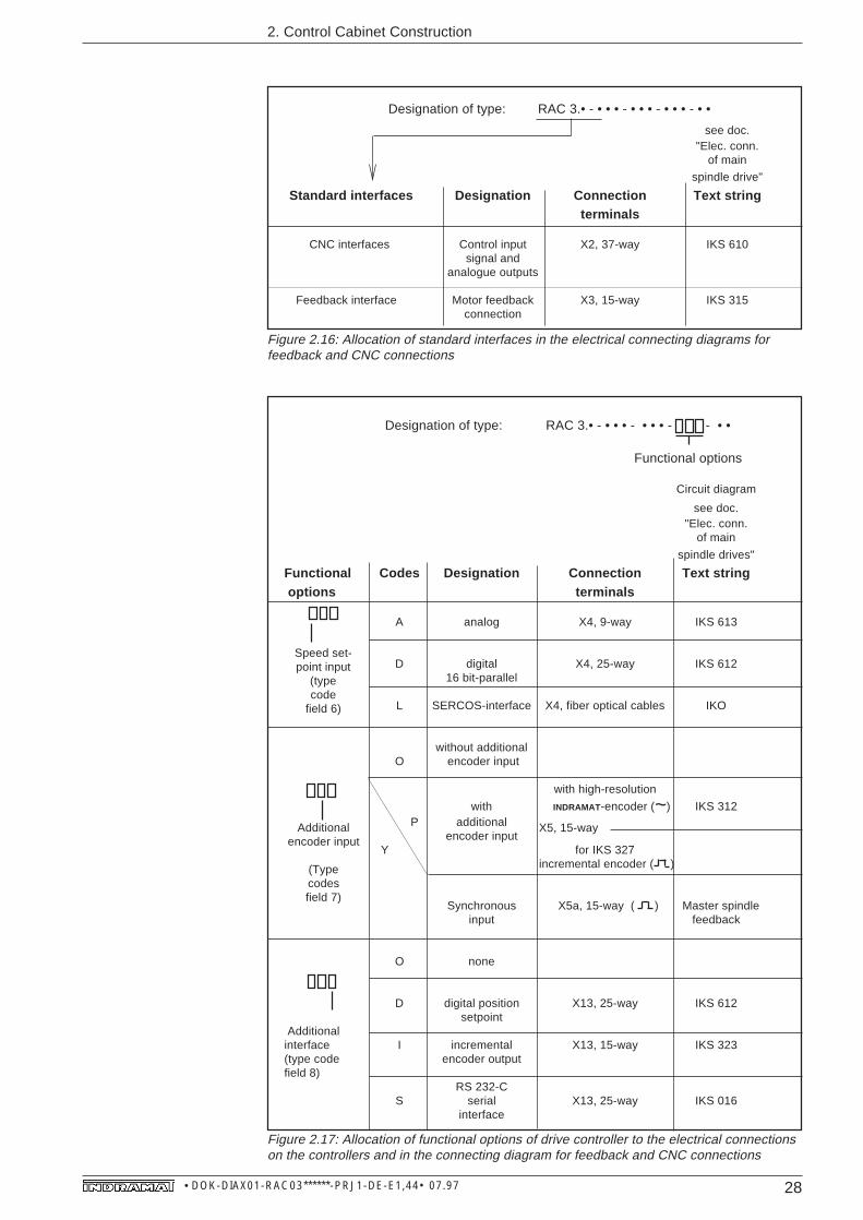
Figure 2.16: Allocation of standard interfaces in the electrical connecting diagrams forfeedback and CNC connections
Figure 2.17: Allocation of functional options of drive controller to the electrical connectionson the controllers and in the connecting diagram for feedback and CNC connections
~
Designation of type: RAC 3.• - • • • - • • • - - • •
Circuit diagram
see doc."Elec. conn.
of main
spindle drives"
Functional Codes Designation Connection Text string options terminals
A analog X4, 9-way IKS 613
D digital X4, 25-way IKS 61216 bit-parallel
L SERCOS-interface X4, fiber optical cables IKO
without additionalO encoder input
with high-resolution
with INDRAMAT-encoder ( ) IKS 312 P additional
encoder input Y for IKS 327
incremental encoder ( )
Synchronous X5a, 15-way ( ) Master spindleinput feedback
O none
D digital position X13, 25-way IKS 612setpoint
Additionalinterface I incremental X13, 15-way IKS 323(type code encoder outputfield 8)
RS 232-CS serial X13, 25-way IKS 016
interface
X5, 15-way
Functional options
Additionalencoder input
(Typecodesfield 7)
Speed set-point input
(typecode
field 6)
see doc."Elec. conn.
of main
spindle drive"
Standard interfaces Designation Connection Text stringterminals
CNC interfaces Control input X2, 37-way IKS 610signal and
analogue outputs
Feedback interface Motor feedback X3, 15-way IKS 315connection
Designation of type: RAC 3.• - • • • - • • • - • • • - • •
29 • DOK-DIAX01-RAC03******-PRJ1-DE-E1,44• 07.97
2. Control Cabinet Construction
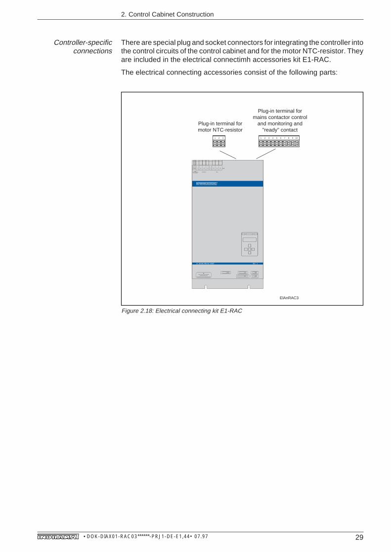
Controller-specificconnections
There are special plug and socket connectors for integrating the controller intothe control circuits of the control cabinet and for the motor NTC-resistor. Theyare included in the electrical connectimh accessories kit E1-RAC.
The electrical connecting accessories consist of the following parts:
Steckklemme für MotorheißleiterSteckklemme für Steuerschaltung
ElAnRAC3
1 2 3 1 2 3 4 5 6 7 8 9 10
Plug-in terminal for motor NTC-resistor
Plug-in terminal for mains contactor control
and monitoring and "ready" contact
X 14
220 VSteuerspannung
Aux. VoltageNetz/Mains
L 3L 2L 1LN
Motor
A 3A 1 A 2
X 4
X 2Prog. Modul AS nicht unter Spannung wechseln
X 3
X 5X 1 3AS
SWITCH OFF VOLTAGE BEFORECHANGING MODULE AS
AC-MAINSPINDLE DRIVE RAC 3
Figure 2.18: Electrical connecting kit E1-RAC
30 • DOK-DIAX01-RAC03******-PRJ1-DE-E1,44• 07.97
2. Control Cabinet Construction
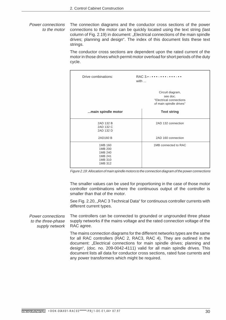
Power connectionsto the motor
The connection diagrams and the conductor cross sections of the powerconnections to the motor can be quickly located using the text string (lastcolumn of Fig. 2.19) in document: „Electrical connections of the main spindledrives; planning and design“. The index of this document lists these textstrings.
The conductor cross sections are dependent upon the rated current of themotor in those drives which permit motor overload for short periods of the dutycycle.
Drive combinations: RAC 3.• - • • • - • • • - • • • - • •with ...
Circuit diagram,see doc.
"Electrical connectionsof main spindle drives"
...main spindle motor Text string
2AD 132 B 2AD 132 connection2AD 132 C2AD 132 D
2AD160 B 2AD 160 connection
1MB 160 1MB connected to RAC1MB 2001MB 2401MB 2411MB 3101MB 312
Figure 2.19: Allocation of main spindle motors to the connection diagram of the power connections
The smaller values can be used for proportioning in the case of those motorcontroller combinations where the continuous output of the controller issmaller than that of the motor.
See Fig. 2.20, „RAC 3 Technical Data“ for continuous controller currents withdifferent current types.
The controllers can be connected to grounded or ungrounded three phasesupply networks if the mains voltage and the rated connection voltage of theRAC agree.
The mains connection diagrams for the different networks types are the samefor all RAC controllers (RAC 2, RAC3, RAC 4). They are outlined in thedocument: „Electrical connections for main spindle drives; planning anddesign“, (doc. no. 209-0042-4111) valid for all main spindle drives. Thisdocument lists all data for conductor cross sections, rated fuse currents andany power transformers which might be required.
Power connectionsto the three-phase
supply network

31 • DOK-DIAX01-RAC03******-PRJ1-DE-E1,44• 07.97
2. Control Cabinet Construction
Designation Symbol Unit
Cooling by means of mounted fan
Rated supply voltage U(AC) V 3 x AC 380 - 460 V, ± 10%, 50 - 60 Hz
Control voltage U(AC)
V AC 230 V, ± 10%, 50 - 60 Hz; 200 VA
Continuous controller current I(cont) A 70 92 92
Continuous controller output(with reference to motor output shaft) P
(cont)kW 26 35 35
Continuous output with 8kHz operation(only RAC 3.5) P(cont) kW 22 30 30
Peak controller output(with reference to motor output shaft) P
(max)kW 26 40 55
Continuous regeneration output(with reference to motor output shaft) P(reg.) kW 18 27 27
Peak regeneration output (max. 5 sec.)(with reference to motor output shaft) P(max. reg.) kW 26 40 55
Weights
Controller weight m kg 49
Weight of accessories M1-RAC 3.1(hose cooling) m kg 1,7
Environmental conditions
Perm. ambient temperature rangewith rated data °Celsius +5 … +45
Max. perm. ambient temperaturewith rated data reduced to 80% °Celsius +55
Storage and transportation temperature °Celsius -30 … +85
Installation altitude without a reductionin rated data meters above sea level max. 1000
Permissible humidity as per humidity class F as per DIN 40 040
Protection category IP 10 as per EN 60 529 (DIN VDE 0470)
RA
C 3
.• -
100
- •
••
- •
••
- •
•
RA
C 3
.• -
150-
••
• -
••
• -
• •
RA
C 3
.5-2
00-
••
• -
••
• -
• •
2.5. Summary of technical data
Figure 2.20: The technical data for the RAC 3
32 • DOK-DIAX01-RAC03******-PRJ1-DE-E1,44• 07.97
2. Control Cabinet Construction
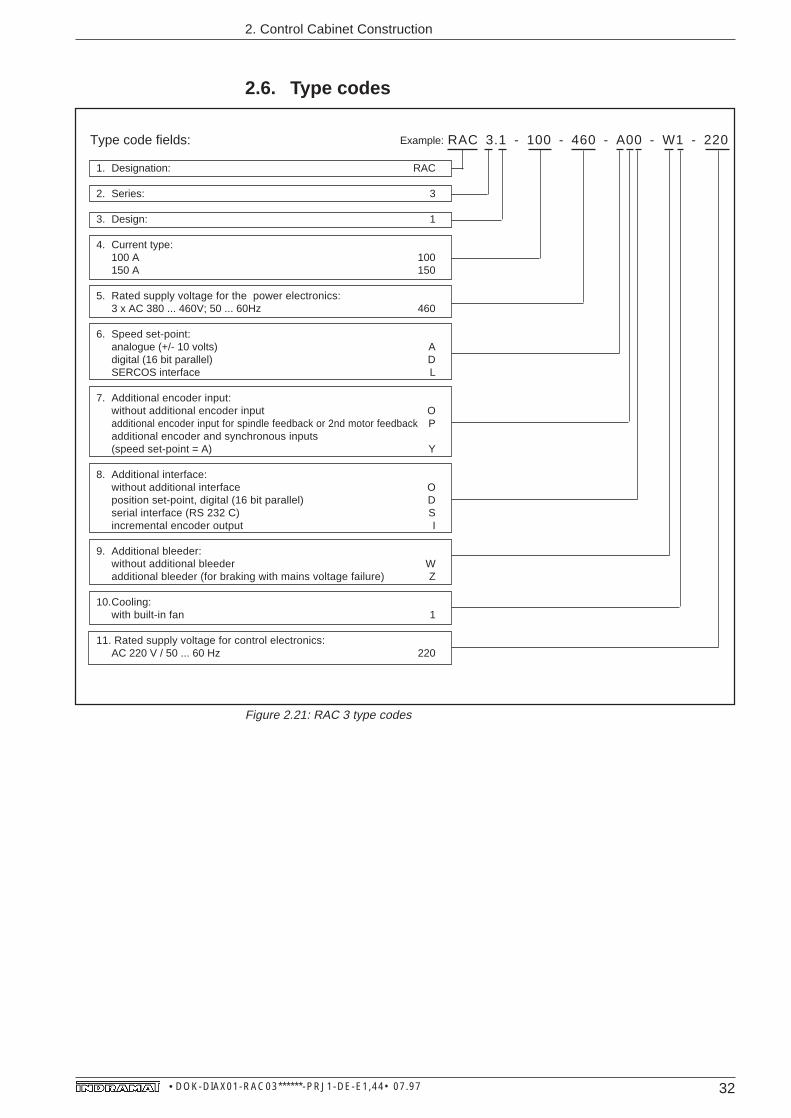
2.6. Type codes
1. Designation: RAC
2. Series: 3
3. Design: 1
4. Current type:100 A 100150 A 150
5. Rated supply voltage for the power electronics:3 x AC 380 ... 460V; 50 ... 60Hz 460
6. Speed set-point:analogue (+/- 10 volts) Adigital (16 bit parallel) DSERCOS interface L
7. Additional encoder input:without additional encoder input Oadditional encoder input for spindle feedback or 2nd motor feedback Padditional encoder and synchronous inputs(speed set-point = A) Y
8. Additional interface:without additional interface Oposition set-point, digital (16 bit parallel) Dserial interface (RS 232 C) Sincremental encoder output I
9. Additional bleeder:without additional bleeder Wadditional bleeder (for braking with mains voltage failure) Z
10.Cooling:with built-in fan 1
11. Rated supply voltage for control electronics:AC 220 V / 50 ... 60 Hz 220
Type code fields: RAC 3.1 - 100 - 460 - A00 - W1 - 220
Figure 2.21: RAC 3 type codes
Example:

33 • DOK-DIAX01-RAC03******-PRJ1-DE-E1,44• 07.97
3. AS programming module
The AS programming module plugged into the controller matches the control-ler to the main spindle motor and implements main spindle drive characteris-tics.
INDRAMAT supplies a matching AS programming module (standard designas per selection data) for every main spindle drive offered.
INDRAMAT main spindle drives are microprocessor controlled.
The main spindle drive is immediately ready at the initial run without anyadjustment work being necessary. This is because of the AS programmingmodule. The only prerequisites are proper connecting and proper commis-sioning (see Section 9).
Parameters can be used to adapt INDRAMAT main spindle drives to plantconditions and the demands of an application.
Operating software and parameters are stored on the AS programmingmodule. In the event that a unit needs to be exchanged, the controller requiresno readjusting as it is immediately adapted to both motor and plant by simplyplugging in the programming module thus far used and, therefore, alreadyadapted.
It is easy to duplicate already adapted programming modules for additional,similar machines. This is done with either a parameter duplicating adapter orwith serial interfaces and a storage device (PC or something similar).
The software has two sets of parameters:
• drive-related, and,
• application-related.
The drive-related parameters affect the operating characteristics of the drive.INDRAMAT defines and fixes the appropriate parameter values to implementthe characteristics of the drives offered.
The application-related parameters activate or affect, according to applica-tion, the functions of the main spindle drive and adapt them to the reality of theplant.
The method of input and making changes in parameter values is the same inall INDRAMAT main spindle drives. The keypad on the control panel of thedrive controller is used for this purpose.
For detailled instructions see the Section, „Operating the drive controller“, inthe docucment: „AC main spindle drives with asynchronous motors or frame-less spindle motors, description of application“, (doc. no. 209-0041-4109).
3. AS programming module
Rapid commissioningof drive
Advantages of unitexchange
Duplication
Parameters
Parameter valueinput and change

34 • DOK-DIAX01-RAC03******-PRJ1-DE-E1,44• 07.97
3. AS programming module
3.1. Types of AS programming modulesThe AS programming module contains the application-related parametervalues as defined by INDRAMAT.
The application-related parameters are preset values. The plant or applica-tion-dependent parameter values are stored on site.
The customer is responsible for the documentation and the administration ofthese facility- and application-dependent parameter values.
If INDRAMAT is to document, administer and deliver a programming moduleafter it has been filled with both facility- and application-dependent parametervalues, then it is necessary to fix a customer-specific programming module.This is done upon customer request, for an additional fee, and in agreementwith INDRAMAT.
3.2. The compatibility of AS programming modulesA state-of-the-art (AS programming module updating) programming modulefor the operation of the drive is automatically part of the delivery. No changein an order is necessary (type designation). Any updated programmingmodule is compatible with all programming modules already delivered.
It is not necessary to make any changes in a programming module order.Thereshould be no doubt that the drive being operated is state-of-the-art.
This means:
• software fault-recovery,
• an expansion of the range of functions without impairing existing functions,
• and, improved parameter values for motor-controller combinations.
Standard
Customer-specific(for large series)
Updating ASprogramming modules
35 • DOK-DIAX01-RAC03******-PRJ1-DE-E1,44• 07.97
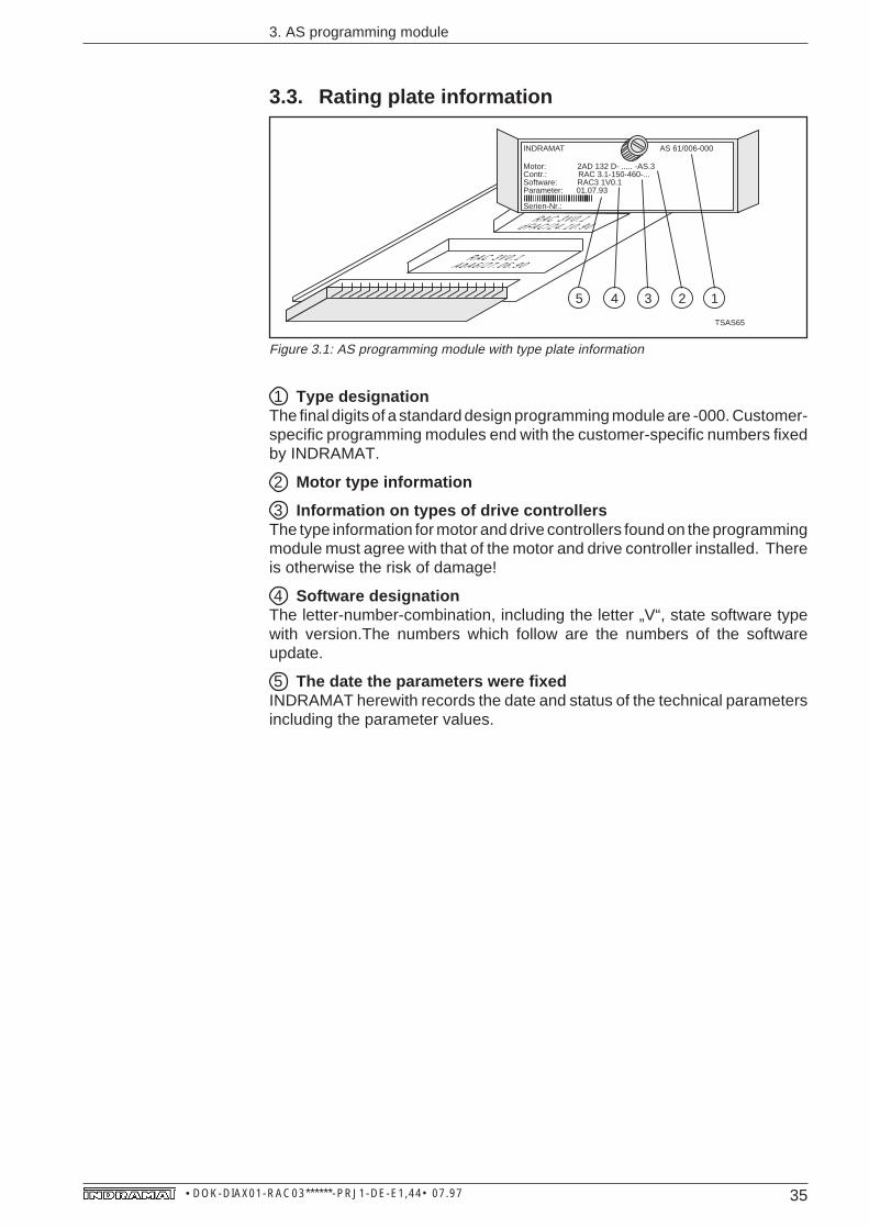
3. AS programming module
1 Type designationThe final digits of a standard design programming module are -000. Customer-specific programming modules end with the customer-specific numbers fixedby INDRAMAT.
2 Motor type information
3 Information on types of drive controllersThe type information for motor and drive controllers found on the programmingmodule must agree with that of the motor and drive controller installed. Thereis otherwise the risk of damage!
4 Software designationThe letter-number-combination, including the letter „V“, state software typewith version.The numbers which follow are the numbers of the softwareupdate.
5 The date the parameters were fixedINDRAMAT herewith records the date and status of the technical parametersincluding the parameter values.
3.3. Rating plate information
TSAS65
R A C 3 V 0 . 1d F A C / 2 4 . 1 0 . 9 0
R A C 3 V 0 . 1 A b A 6 / 2 7 . 0 6 . 9 0
45 23 1
Motor: 2AD 132 D- ..... -AS.3Contr.: RAC 3.1-150-460-...Software: RAC3 1V0.1Parameter: 01.07.93
Serien-Nr.:
INDRAMAT AS 61/006-000
Figure 3.1: AS programming module with type plate information

36 • DOK-DIAX01-RAC03******-PRJ1-DE-E1,44• 07.97
3. AS programming module
3.4. Type codes
Type code fields:
1. Designation: AS
2. Main spindle drive controller:KDA 3.2 •3RAC 2.2 •5RAC 3.1 •6TDA 1.1 •7RAC 4.1 •8KDA 3.3 13RAC 2.3 15RAC 3.5 16TDA 1.3 17RAC 4.3 18
3. Software code digit3.1 Main spindle drive (standard)
(all combinations not listed below) 13.2 Servo drive (always includes incremental encoder output) 23.3 Main spindle drive with incremental encoder output 33.4 Main spindle drive with SERCOS interface 43.5 Main spindle drive with additional function 53.6 Servo drive with SERCOS interface 6
4. Motor feedbackHigh-resolution motor feedback (standard) 0Incremental encoder motor feedback 2
5. Code digit for motor-controller combinationDefined and documented by INDRAMAT e.g. 04
6. DesignStandard 000Customer-specific, e.g.,: 003 003
Comments:On 3.2: main spindle drive controller, e.g., KDA always requires additional interface„incremental encoder output“;On 3.3: main spindle drive controller, e.g., KDA requires additional interface„incremental encoder output“;On 3.4: main spindle drive controller, e.g., KDA requires additional interface speed set-point„SERCOS interface“.
1 Main spindle drive controllers are not available with software code digits „3“ and „5“.• = blank character
Example: AS163/004-002
Quellverweis: INN 07.50
11111
Figure 3.2: Type codes for AS programming modules
37 • DOK-DIAX01-RAC03******-PRJ1-DE-E1,44• 07.97
4. Condition at delivery
4. Condition upon delivery
The RAC 3 with all its accessories comes packed in a carton (transportcontainer) upon delivery. Accessories are packed in plastic bags looselyplaced in the carton (possibly M1-RAC3 and E1-RAC).
Covers needed to accomodate the structural alterations when cooling thecontrol cabinet with outside air are packed in one plastic bag and attached tothe drive controller.
An envelope containing two delivery slips is attached to the transport con-tainer. There are no additional delivery documents unless specifically re-quested.
Simply split open the glue strips to unpack without damaging the merchandise.
The RAC 3 drive controller is delivered with control cabinet outside air cooling(see Sec. 1). Current and insulation have also been quality controlled as perVDE 0160.

38 • DOK-DIAX01-RAC03******-PRJ1-DE-E1,44• 07.97
5. Identifying the merchandise
An original and a copy of the delivery slip are attached to the transportcontainer. The parts of the delivery can be packed in several cartons (transportcontainers). This is noted on the delivery slip, or freight invoice.
The delivery slip lists the merchandise by name and order identification.
The transport container contains the individually packed drive controller andaccessories in the case of a mixed order. In the case of multiple orders of thesame equipment, the accessories may be in a separate transport container.
There is a barcode sticker on the RAC 3 packaging. It identifies the contentsand the order.
5. Identifying the merchandise
RAC 3 main spindledrive controller
Customer order no.
Unit serial no.
Item no.on del. slip
Coded pos. no.on del. slip
Coded typedesignation
Codedequipment
serial no.
Codedconsignment no.
Companydelivered to
Consignment no.
Type-designation
BarcodeRAC41.tif
Figure 5.1: Barcode sticker on the RAC packaging (example)
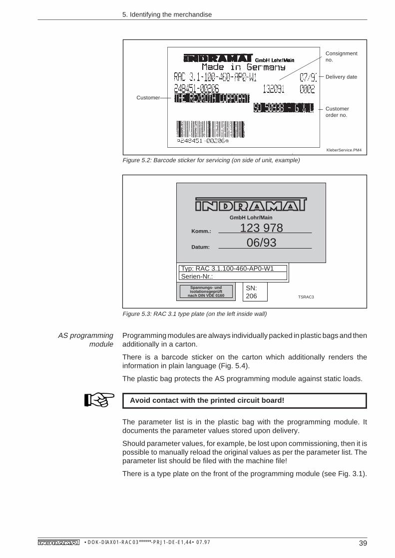
The RAC 3 itself has a sticker on the side which lists all required information.It corresponds to the barcode sticker and lists the delivery date (see Fig. 5.2).
There is a type plate on the lower left hand corner of the RAC 3, inside thehousing (see Fig. 5.3).
39 • DOK-DIAX01-RAC03******-PRJ1-DE-E1,44• 07.97
5. Identifying the merchandise
KleberService.PM4
Consignmentno.
Delivery date
Customerorder no.
Customer
GmbH Lohr/Main
Komm.:
Datum:
123 97806/93
Typ: RAC 3.1.100-460-AP0-W1Serien-Nr.:
Spannungs- undisolationsgeprüft
nach DIN VDE 0160 TSRAC3
SN:206
Figure 5.2: Barcode sticker for servicing (on side of unit, example)
Figure 5.3: RAC 3.1 type plate (on the left inside wall)
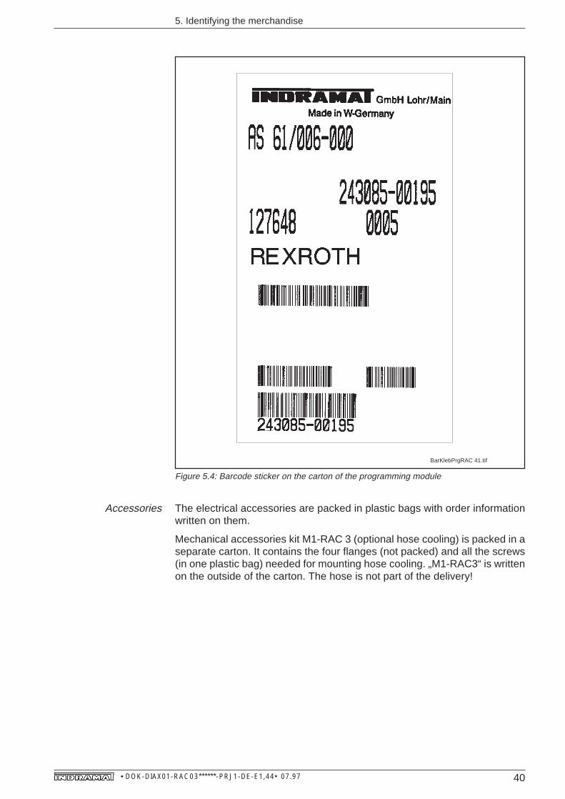
Programming modules are always individually packed in plastic bags and thenadditionally in a carton.
There is a barcode sticker on the carton which additionally renders theinformation in plain language (Fig. 5.4).
The plastic bag protects the AS programming module against static loads.
-Avoid contact with the printed circuit board!
The parameter list is in the plastic bag with the programming module. Itdocuments the parameter values stored upon delivery.
Should parameter values, for example, be lost upon commissioning, then it ispossible to manually reload the original values as per the parameter list. Theparameter list should be filed with the machine file!
There is a type plate on the front of the programming module (see Fig. 3.1).
AS programmingmodule
40 • DOK-DIAX01-RAC03******-PRJ1-DE-E1,44• 07.97
5. Identifying the merchandise
BarKlebPrgRAC 41.tif
Figure 5.4: Barcode sticker on the carton of the programming module
The electrical accessories are packed in plastic bags with order informationwritten on them.
Mechanical accessories kit M1-RAC 3 (optional hose cooling) is packed in aseparate carton. It contains the four flanges (not packed) and all the screws(in one plastic bag) needed for mounting hose cooling. „M1-RAC3“ is writtenon the outside of the carton. The hose is not part of the delivery!
Accessories
41 • DOK-DIAX01-RAC03******-PRJ1-DE-E1,44• 07.97
6. Storage and transportation
The drive controllers must be stored dry, dust and impact-free, permissibletemperature range is -30 to +85 degrees C.
Use a vibration-damping base during transportation in the event of the dangerof excessive vibrations!
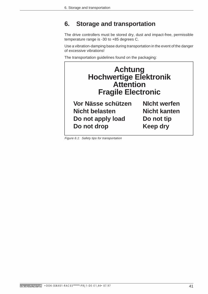
The transportation guidelines found on the packaging:
6. Storage and transportation
AchtungHochwertige Elektronik
AttentionFragile Electronic
Vor Nässe schützen NIcht werfenNicht belasten Nicht kantenDo not apply load Do not tipDo not drop Keep dry
Figure 6.1: Safety tips for transportation
42 • DOK-DIAX01-RAC03******-PRJ1-DE-E1,44• 07.97
7. Assembly
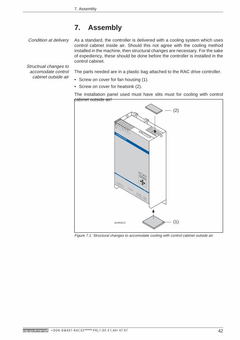
As a standard, the controller is delivered with a cooling system which usescontrol cabinet inside air. Should this not agree with the cooling methodinstalled in the machine, then structural changes are necessary. For the sakeof expediency, these should be done before the controller is installed in thecontrol cabinet.
The parts needed are in a plastic bag attached to the RAC drive controller.
• Screw on cover for fan housing (1).
• Screw on cover for heatsink (2).
The installation panel used must have slits must for cooling with controlcabinet outside air!
7. Assembly
Condition at delivery
Structrual changes toaccomodate control
cabinet outside air
ALKRAC3 (1)
(2)
X 14
220 VSteuerspannung
Aux. Voltage
Netz/Mains
L3
L2
L1
LN
Motor
A3
A1 A2
X 4
X 2
Prog. Modul AS nicht unter Spannung wechseln
X 3
X 5
X 1 3
AS
SWITCH OFF VOLTAGE BEFORE
CHANGING MODULE AS
AC-MAINSPINDLE DRIVE RAC 3
Figure 7.1: Structural changes to accomodate cooling with control cabinet outside air.
43 • DOK-DIAX01-RAC03******-PRJ1-DE-E1,44• 07.97
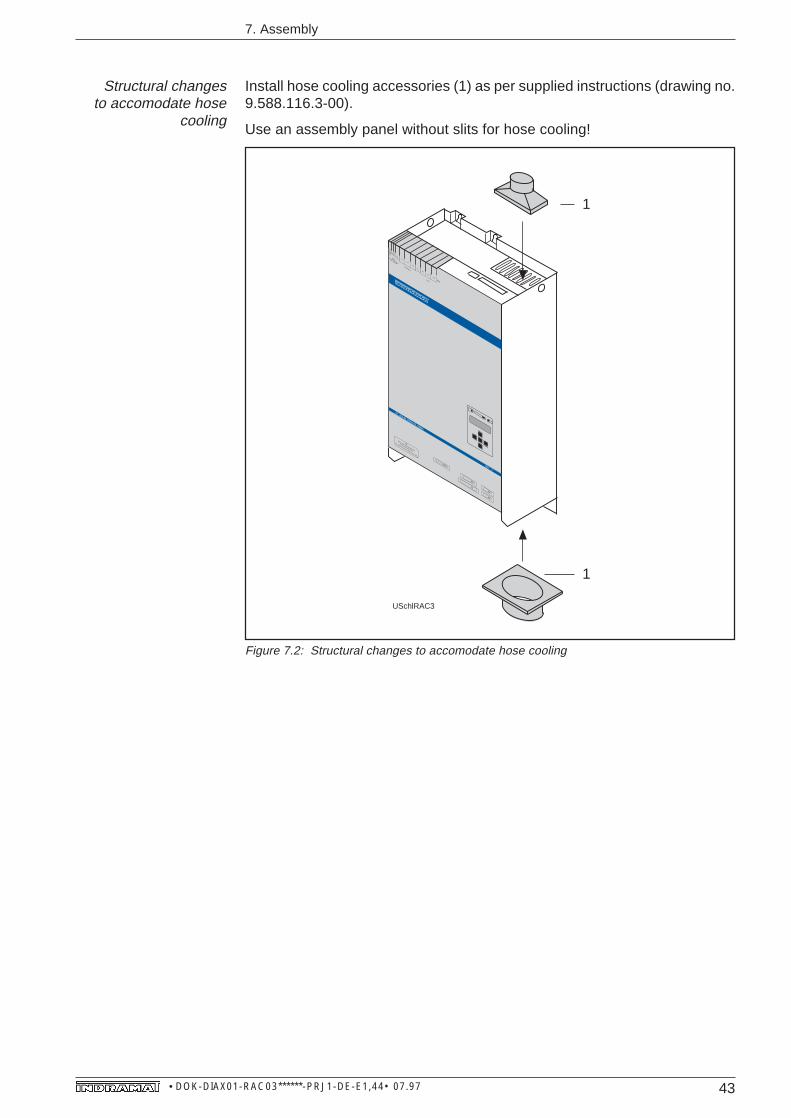
Structural changesto accomodate hose
cooling
Install hose cooling accessories (1) as per supplied instructions (drawing no.9.588.116.3-00).
Use an assembly panel without slits for hose cooling!
7. Assembly
USchlRAC3
1
1
X 14
220 VSteuerspannung
Aux. Voltage
Netz/Mains
L3
L2
L1
LN
Motor
A3
A1 A2
X 4
X 2
Prog. Modul AS nicht unter Spannung wechseln
X 3
X 5
X 1 3
AS
SWITCH OFF VOLTAGE BEFORE
CHANGING MODULE AS
AC-MAINSPINDLE DRIVE RAC 3
Figure 7.2: Structural changes to accomodate hose cooling

44 • DOK-DIAX01-RAC03******-PRJ1-DE-E1,44• 07.97
7. Assembly
7.1. Installing the drive controller in the control cabinet
The following parts are needed for installation in the control cabinet
• RAC 3 drive controller
• lifting device (RAC 3 weight = 49 kg)
The mouting panel or back wall of the control cabinet has been made readyfor the intended type of cooling and is hanging on the screws which are inplace. Tighten the screws.
The programming module is plugged into the socket located on the lower lefthand edge of the front panel of the RAC 3. Insert the programming module andsecure it with a knurling screw!
The programming module must be plugged in and secured with aknurling screw before the RAC 3 is commissioned.
Installing the drivecontroller
Plug in programmingmodule
X 14
220 VSteuerspannung
Aux. Voltage
Netz/Mains
L3
L2
L1
LN
Motor
A3
A1 A2
X 4
X 2
Prog. Modul AS nicht unter Spannung wechseln
X 3
X 5
X 1 3
AS
SWITCH OFF VOLTAGE BEFORE
CHANGING MODULE AS
AC-MAINSPINDLE DRIVE RAC 3
GERAC3
Programming module
Figure 7.3: Installing the RAC 3
45 • DOK-DIAX01-RAC03******-PRJ1-DE-E1,44• 07.97
8. Installation guidelines
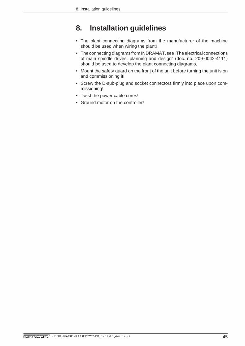
• The plant connecting diagrams from the manufacturer of the machineshould be used when wiring the plant!
• The connecting diagrams from INDRAMAT, see „The electrical connectionsof main spindle drives; planning and design“ (doc. no. 209-0042-4111)should be used to develop the plant connecting diagrams.
• Mount the safety guard on the front of the unit before turning the unit is onand commissioning it!
• Screw the D-sub-plug and socket connectors firmly into place upon com-missioning!
• Twist the power cable cores!
• Ground motor on the controller!
8. Installation guidelines

46 • DOK-DIAX01-RAC03******-PRJ1-DE-E1,44• 07.97
9. Commissioning guidelines
9. Commissioning guidelines
Commissioning is the same for all main spindle drive controllers (RAC 2, RAC3, RAC 4). For this reason and because of the range of functions, thecommissioning guidelines for all INDRAMAT main spindle drives are ex-plained only once in the document entitled „AC main spindle drives withcontrolled asynchronous motors or frameless spindle motors – description ofapplication“, (doc. no. 209-0041-4109)! The procedure described herein isvalid for all controllers.

47 • DOK-DIAX01-RAC03******-PRJ1-DE-E1,44• 07.97
10. Servicing guidelines
10. Servicing guidelines
10.1. Fault diagnosisThe RAC 3 diagnosis drive faults via the display on the control panel. The drivebrakes until standstill in the presence of a fault. The RAC 3 then cuts power.Fault diagnosis is the same in the different main spindle drive controllers.
For this reason, the fault diagnoses and guidelines on fault recovery aredescribed in the documentation valid for all INDRAMAT main spindle drivesentitled: „AC main spindle drives with controlled asynchronous motors orframeless spindle motors – description of application“, (doc. no. 209-0041-4109).
10.2. Defective controllerIf an exchange should become necessary, then the drive can be adaptedwithout any difficulty. Simply remove the programming module from thedefective unit and then plug it into the replacement unit. The drive with the newcontroller behaves the same as the original. This is because the drive andmachine-specific adaptation of the RAC 3 are realized in the AS programmingmodule.
Should work on the drive controller become necessary because of a defect,then the following procedure must be followed:
• Open the power supply switch and secure it against being switched back onbefore working on any electrical equipment. The drives must be standingstill.
• Only INDRAMAT customer service personnel or appropriately trainedtechnical personnel may perform repairs on the unit!
• Detach and remove all connections for a controller exchange. Detach thefixing screws and take the RAC 3 out of the control cabinet.
• Hang the replacement unit onto the fixing screws and then tighten thescrews. Remove the programming module from the defective unit, plug itinto the replacement and secure it against falling out by tightening theknurling screws.
Do not remove or plug in the programming module when the unit islive! The fixing screw on the programming module must be tight-ened prior to commissioning the RAC 3!
• Connect the new RAC 3 as per the plant connecting diagram and mount thesafety guard.
• Recommission plant (see documentation „AC main drives with controlledasynchronous motors or frameless spindle motors — description of appli-cation“, (doc. no. 209-0041-4109), the section on commissioning.
• Fill out the return card for merchandise return/fault protocol! This return cardis depicted in Fig. 10.1 and can be copied for your use and convenience!
• Return defective unit with completed return card to the appropriateINDRAMAT customer service representative.
Repairs
Controller exchange
Returning adefective controller

48 • DOK-DIAX01-RAC03******-PRJ1-DE-E1,44• 07.97
10. Servicing guidelines
Abb. 10.1: Reparatur-Begleitkarte
Date:Completed by: Company/Town:
Supply job no.:SN:When replacing single components,enter component designation
SN: Shipment date:
Machine manufacturer/Company: Type:
Fault in axisno.
Operating hours:
Machine no.:
Date fault occurred:
if necessary -commissioning date
Fault status:
Fault
Additional information:(e.g. LED diagnosismessages in display)
Cause of fault:
always presentoccurs sporadicallyoccurs after _____ hrsoccurs on impact/vibrationis temperature-dependentother
*
*
*
not knownfault connectionext. short-circuitmech. damageloose cable connectionsother
*
*
*
Supplementary information
no functiondrive running irregularlyuncontrolled drive motionfault in only one directionburnt-out fuse on supplyother
General details:
mechanical problemsfailure of power supplyfailure of controllermotor failurecable breakother
faulty control voltagemains power fuse burnt outdefective fandefective bleeder resistorfaulty power supply voltageconnection bolt sheared offother
Related incidents:Controller, supply unit,amplifier, mains power:
no functionfaulty displayno set-point outputdiagnosisdimensional shift in directionE-STOP circuit brokenpos. control loop does not closeprogramme sequence faultfaulty internal auxiliary function(outputs)acknowledgements not accepted(inputs)other
Control system:
defective thermocoupledefective brakedefective fandefective feedbackdefective speed encodersignaldefective BLC signalearthing short-circuitoverheatingother
Motor: Remarks:
Repair Cardfor INDRAMAT equipment and components
horizontalvertical

49 • DOK-DIAX01-RAC03******-PRJ1-DE-E1,44• 07.97
11. Index
11. Index
AAdditional interface 28additional interfaces 8Allocation of functional options 28Allocation of main spindle motors 30Allocation of standard interfaces 28ambient humidity 12ambient temperature 11AS programming module 33
CCommissioning guidelines 46Condition upon delivery 37Conditions for Bb „ready“, 26Connecting diagram 24Connections, mains 27control circuit 26control voltage connection 8Controller exchange 47Controller-specific connections 24, 29Cooling with air inside the control cabine 6Cooling with air outside the control cabine 6
DDefective controller 47Dimensional data for hose cooling 19Dimensions for cooling with air inside the control 17Dimensions for cooling with air outside of the con 16Dimensions for hose cooling 18direct mains connection 8Drill diagram 15
EElectrical connecting accessories 29Electrical data 24Environmental conditions 11
FFault diagnosis 47Feedback and CNC connections 24feedback interface 8Feedback, motor 24Feedback, motor connection 24Flange for hose cooling 19
50 • DOK-DIAX01-RAC03******-PRJ1-DE-E1,44• 07.97
11. Index
IIdentifying the merchandise 38Installation altitude 12Installation guidelines 45Installing the drive controller 44interface for CNC control 8interface for monitoring and control 8
Kkeypad 9
MMain spindle feedback 24main spindle motor 10mains connection cable 10Mains contactor 24Mains contactor control and monitoring 24Mains contactor monitoring 24Mechanical data 14motor fan cable 10motor feedback cable 10motor NTC connection 8motor power cable 10motor power connection 8
Nnterface for CNC control 8
Ooptional interface 9
PPlug and socket connectors for NTC resistors and c 29Power connection to the three-phase supply networ 30Power connections to the motor 30Power dissipation 20Power supply unit 26Principle circuit diagram 26Programming module 9
RRAC 3 installation 44Repairs 47Return card 47Returns 47

51 • DOK-DIAX01-RAC03******-PRJ1-DE-E1,44• 07.97
11. Index
SServicing guidelines 47Spindle, feedback 24Storage and transportation 41Structrual changes to control cabinet outside air 42Structural changes to hose cooling 43Synchronous input 27
TTechnical data 31The use of cooling devices in control cabinets 22Thermal data 20Type codes 32Type codes, RAC 3 32Type codes, AS programming module 36
WWeights 31
52 • DOK-DIAX01-RAC03******-PRJ1-DE-E1,44• 07.97
12. Supplementary documentation
Sel
ectio
n(d
etai
ls, o
rder
)
Selection information- summary of the AC main drive system- power range- technical functions of the AC main spindle drives- selection protocol and parts list- available versions
AC Main spindle drivewith 2AD controlled main
spindle drive motor
2AD
Doc. no.: 9.567.013.4
AC Main spindle drivewith 2AD controlled main spindle drive motor
AC main spindle driveswith controlled
asynchronous motor orframeless spindle motor
AC main spindle drives with controlled asyn-chronous motor or frameless spindle motor
Description of application- AC main spindle drive commissioning- operating the drive controller- the functions of the drive controller- diagnoses and fault recovery- summary of parameters and interfaces
Doc. no. 209-0041-4109
RAC4RAC3
RAC2 Electricalconnections
for maindrives
Asynchronous motor
225
Main spindle motor
Planning and design- machine construction- delivery, storage, transportation- assembly and installation
guidelines
Main spindle drive controller
Planning and design- control cabinet construction- AS programming module- delivery, storage, transportation- assembly and installation guidelines
KDA 3.2, Doc. no. 209-0042-4110TDA 1.1, Doc. no. 209-0042-4112RAC 2, Doc. no. 209-0042-4115RAC 3, Doc. no. 209-0042-4116RAC 4, Doc. no. 209-0042-4113
2AD 100, Doc. no. 9.567.009.42AD 101, Doc. no. 9.567.018.42AD 132, Doc. no. 9.567.010.42AD 160, Doc. no. 9.567.011.42AD 180, Doc. no. 9.567.012.42AD 200 - in preparation2AD 225 - in preparation
Electrical connectionsfor main drives
Planning and design- general guidelines on
electrical connections- connection diagrams for
feedback and CNCconnections of all mainspindle drives
- connection diagrams for allpower connections in mainspindle drives
You have this document:
12. Supplementary documentationP
lann
ing
and
Des
ign
(con
stru
ctio
n, a
ssem
bly,
inst
allin
g th
e m
achi
ne)
TDA1Drive controller
KDA3
Doc. No. 209-0042-4111
Asynchronous motor
200Asynchronous motor
180Asynchronous motor
160Asynchronous motor
132Asynchronous motor
101Asynchroous nmotor
2AD100
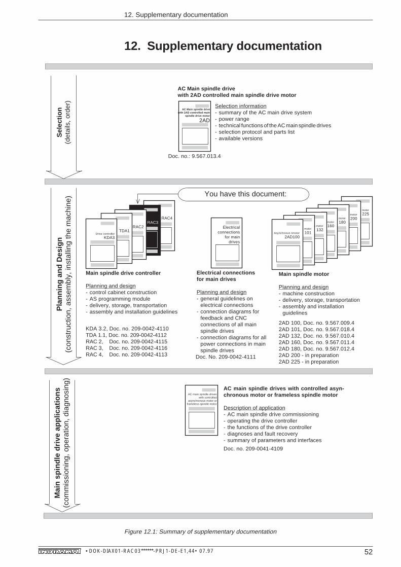
Figure 12.1: Summary of supplementary documentation
Mai
n sp
indl
e dr
ive
appl
icat
ions
(com
mis
sion
ing,
ope
ratio
n, d
iagn
osin
g)

53 • DOK-DIAX01-RAC03******-PRJ1-DE-E1,44• 07.97
12. Supplementary documentation
1MB- Stator1MB
- Rotor
Summary documentation
- high-resolution main spindle positionencoder• planning and design
doc. no. 209-0042-4119- IGS incremental encoder output
doc. no. 9.568.015.4- HGV high-resolution encoder junction
doc. no. 9.568.010.4- Absolute value encoder attachment
for 2AD 132, 2AD 160, 2AD 180doc. no. 9.568.020.4
Absolute valueencoder
2ADHGV
IGSHigh-resolutionmain spindle
position encoder
Selection information- summary of the AC main spindle drive system- power range- technical functions of the AC main spindle
drive- selection protocols and parts lists- available versions
AC main spindle drivewith controlled 1MB
frameless spindle motor
1MB
Doc. no. 9.567.012.4
AC main spindle drivewith controlled 1MB frameless spindle motor
AC main spindledrive with 2K
changeoverplanetary gearboxes
AC main spindle drive with 2ADcontrolled asynchronous motor and2KB changeover planetary gearboxes
Selection information- summary of the
AC main drive system- power range- order guidelines
Frameless spindle motor
Assembly guidelines- delivery, handling,
transportation- assembly- cooling guidelines
Doc. no. 9.567.022.4
Planning and design- machine construction- integration into the cooling system- electrical and coolant connections- delivery
1MB 160, Doc. no. 9.576.014.41MB 200, Doc. no. 9.576.016.41MB 240/241, Doc. no. 9.576.015.41MB 310/312, Doc. no. 9.576.008.41MB 375, Doc. no. 9.576.007.4
Sel
ectio
n(d
etai
ls, o
rder
)P
lann
ing
and
Des
ign
(con
stru
ctio
n, a
ssem
bly,
inst
allin
g th
e m
achi
ne)
Mai
n sp
indl
e dr
ive
appl
icat
ions
(com
mis
sion
ing,
ope
ratio
n, d
iagn
osin
g)
Framlessspindle motor
375Framless
spindle motor
310Framless
spindle motor
240Framless
spindle motor
200Framless
spindle motor
1MB 160
Stator, Doc. no. 9.600.063.4Rotor, Doc. no. 9.600.062.4

Indramat