ra890g protectorelay™ primary control - lesman · 1 60-2035—9 ra890g protectorelay™ primary...
TRANSCRIPT
1 60-2035—9
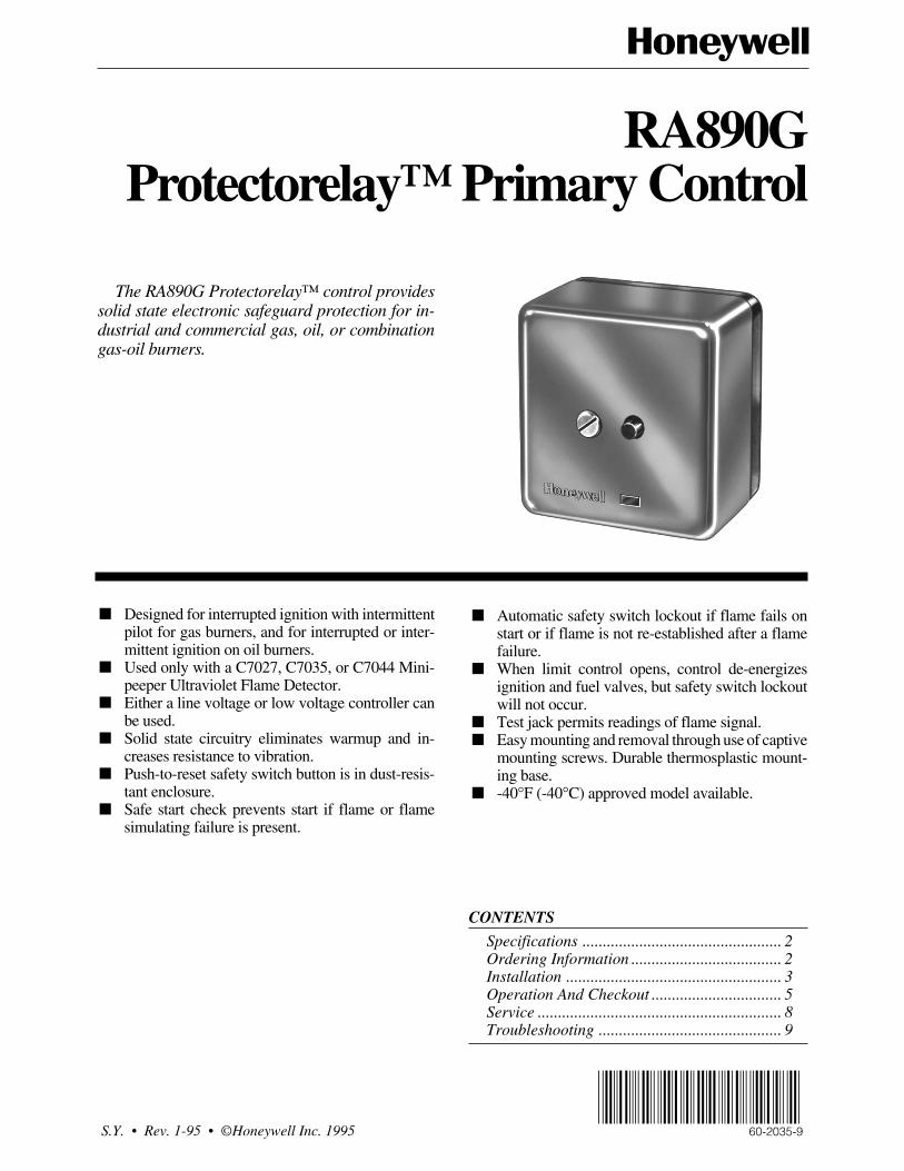
RA890GProtectorelay™ Primary Control
The RA890G Protectorelay™ control providessolid state electronic safeguard protection for in-dustrial and commercial gas, oil, or combinationgas-oil burners.
■ Designed for interrupted ignition with intermittentpilot for gas burners, and for interrupted or inter-mittent ignition on oil burners.
■ Used only with a C7027, C7035, or C7044 Mini-peeper Ultraviolet Flame Detector.
■ Either a line voltage or low voltage controller canbe used.
■ Solid state circuitry eliminates warmup and in-creases resistance to vibration.
■ Push-to-reset safety switch button is in dust-resis-tant enclosure.
■ Safe start check prevents start if flame or flamesimulating failure is present.
■ Automatic safety switch lockout if flame fails onstart or if flame is not re-established after a flamefailure.
■ When limit control opens, control de-energizesignition and fuel valves, but safety switch lockoutwill not occur.
■ Test jack permits readings of flame signal.■ Easy mounting and removal through use of captive
mounting screws. Durable thermosplastic mount-ing base.
■ -40°F (-40°C) approved model available.
CONTENTS
Specifications ................................................. 2Ordering Information ..................................... 2Installation ..................................................... 3Operation And Checkout ................................ 5Service ............................................................ 8Troubleshooting ............................................. 9
S.Y. • Rev. 1-95 • ©Honeywell Inc. 1995 60-2035-9
60-2035—9 2
RA890G
SPECIFICATIONS • ORDERING INFORMATION
SpecificationsTRADELINE® MODELSTRADELINE® models are selected and packaged to pro-
vide ease of stocking, ease of handling, and maximumreplacement value. TRADELINE® model specificationsare the same for standard models except as noted below.
TRADELINE® MODELS AVAILABLE: RA890GProtectorelay™ Primary Control—120 Vac, 50/60 Hz.
STANDARD MODELSMODEL: RA890G Protectorelay™ Primary Control.VOLTAGE AND FREQUENCY: 120V, 208V, 220V, 240V;
50/60 Hz models.VOLT-AMPERE RATING:
60 Hz: 14 VA maximum, 12 VA standby.50 Hz: 18 VA maximum, 17 VA standby.
POWER CONSUMPTION:60 Hz: 9.5W maximum, 3W standby.50 Hz:10W maximum, 4W standby.
FLAME FAILURE RESPONSE TIME: 0.8 or 3 seconds(nominal; separate models). 3 second response time rec-ommended for nonrecycling cutoff system.
FLAME ESTABLISHING PERIOD: Up to 15 seconds(nominal).
RECYCLE TIME: Occurs immediately when flame loss isrecognized. See Flame Failure Response Time.
SAFETY SWITCH TIMING (LOCKOUT TIMING): 15 sec-onds. Timings are proportional with input voltages andtemperatures. For RA890 classified in Underwriters Labo-ratories Inc gas groups 6 and 6a and oil group 8, themaximum safety switch timing with voltages rangingfrom 70 to 110 percent of rated voltage and with ambientsranging from 32°F (0°C) to 115°F (66°C) are allowed tobe as high as 50 seconds.
DIMENSIONS (Including Subbase): Approximately 5 x 5x 5 (127 x 127 x 122 mm).
AMBIENT TEMPERATURE RATING:MINIMUM: Models with 15 second safety switch:
-20°F (-29°C).
Terminal Electrical Load120Vac
240Vac
3 BurnerMotor
Full Load 5.2A 2.6A
Locked Rotor 31.2A 15.6A
Ignitiona 3.0A 1.5A
Pilot Fuel Valve 25VA 25VA
4 Ignitiona 3.0A 1.5A
5 Main Valve (Pilot Duty) 125VA 125VA
Alternate Rating: 25 VA pilot duty plus one ormore motorized valves with total rating of 400VA opening, 200 VA holding.
MAXIMUM: Models without alarm contacts:50 Hz: 115°F, 46°C.60 Hz: 125°F, 52°C.
Models with alarm contacts:50 Hz: 105°F, 41°C.60 Hz: 115°F, 46°C.
ALARM CONTACTS (Optional): Isolated spdt contacts.Alarm terminals are male quick-connects (female quick-connects included for field installation). See rating above.
FLAME DETECTOR: C7027, C7035 or C7044 UltravioletFlame Detector.
MOUNTING: Q270A Universal Mounting Base (orderedseparately).
ELECTRICAL RATINGS:
a If ignition and motor are connected to terminal 3, terminal4 cannot be used. This prevents overloading relay 1K.
Alarm Contacts: 3.0 A at 24 Vac, or 75 VA pilot duty at120 Vac in suitable wiring enclosure.
Low Voltage Control Circuit (T-T): 0.17A.
NOTE: Allowable inrush can be up to ten times the pilot dutyrating.
Ordering InformationWhen purchasing replacement and modernization products from your TRADELINE® wholesaler or distributor, refer to the TradelineCatalog or price sheets for complete ordering number, or specify—
1. Order number specify TRADELINE®, if desired. 4. Alarm contacts, if desired.2. Voltage and frequency. 5. Accessories, if desired.3. Flame response time.
If you have additional questions, need further information, or would like to comment on our products or services, please write or phone:1. Your local Home and Building Control Sales Office (please check the white pages of your phone directory).2. Home and Building Control Customer Logistics
Honeywell Inc., 1885 Douglas Drive NorthMinneapolis, Minnesota 55422-4386
In Canada—Honeywell Limited/Honeywell Limitée, 35 Dynamic Drive, Scarborough, Ontario M1V 4Z9. International Sales andService Offices in all principal cities of the world. Manufacturing in Australia, Canada, Finland, France, Germany, Japan, Mexico,Netherlands, Spain, Taiwan, United Kingdom, U.S.A.
3 60-2035—9
RA890G
SPECIFICATIONS • INSTALLATION
®
American Gas Association Design Certified For -20°F (-29°C). Certificate no. 20-6b.
ACCESSORIES:Models with 15 second safety switch: -20F (-29°C).W136A Microammeter.123514B Flame Simulator.196146 Meter Connector Plug.FSP1535 Test Panel: For operational check of the
RA890E,F,G,H,J or the R4795.118702E Remote Reset Cover Assembly.202471A Cover Assembly with reset button.
InstallationCAUTIONUltraviolet sensing tubes have a life expectancyof 40,000 hours of continuous use within theambient temperature and voltage ratings. Wornout ultraviolet sensing tubes result in failure of thesensing tube to properly discriminate betweenflame conditions.
Systems using the RA890G with the C7027,C7035 and C7044 Flame Detectors should only beused on burners that cycle On and Off at least onceevery 24 hours. Appliances with burners that re-main on for 24 hours continuously or longer shoulduse the C7012E Flame Detector with the R7247CAmplifier or the C7076A Flame Detector with theR7476A Amplifier as the ultraviolet flame detec-tion system.
WHEN INSTALLING THIS PRODUCT…1. Read these instructions carefully. Failure to follow
them could damage the product or cause a hazardouscondition.
2. Check the ratings given in the instructions and on theproduct to make sure the product is suitable for yourapplication.
3. Installer must be a trained, experienced flame safequardcontrol technician.
4. After installation is complete, check out product op-eration as provided in these instructions.
CAUTION1. Disconnect power supply before beginning in-
stallation to prevent electrical shock and equip-ment damage. All wiring must comply with ap-plicable local electrical codes, ordinances, andregulations.
2. Limits must be rated to carry and break current tothe ignition transformer, pilot valve (or first stageoil valve), and main fuel valve(s) simultaneously.
3. All external timers must be Listed or ComponentRecognized by authorities that have jurisdictionfor the specific purposes for which they are used.
Follow the burner manufacturer instructions when sup-plied; otherwise, proceed as follows.
LOCATIONTemperature
Install the RA890G where the surrounding temperaturesremain within the ambient Operating Temperature Ratingslisted in the SPECIFICATIONS section.
HumidityInstall the RA890G where the relative humidity never
reaches the saturation point. Condensation of moisture onthe RA890G may cause enough leakage to short the flamesignal to ground and prevent the burner from starting.
VibrationDo not install the RA890G where it could be subject to
excessive vibration. Vibration shortens the life of the elec-tronic components.
WeatherThe RA890G is not designed to be weathertight. If it is
installed outdoors, use a suitable weathertight enclosure.
MOUNT SUBBASELocate subbase where ambient temperature is within the
specified rating.Mount the subbase so that the top and bottom are hori-
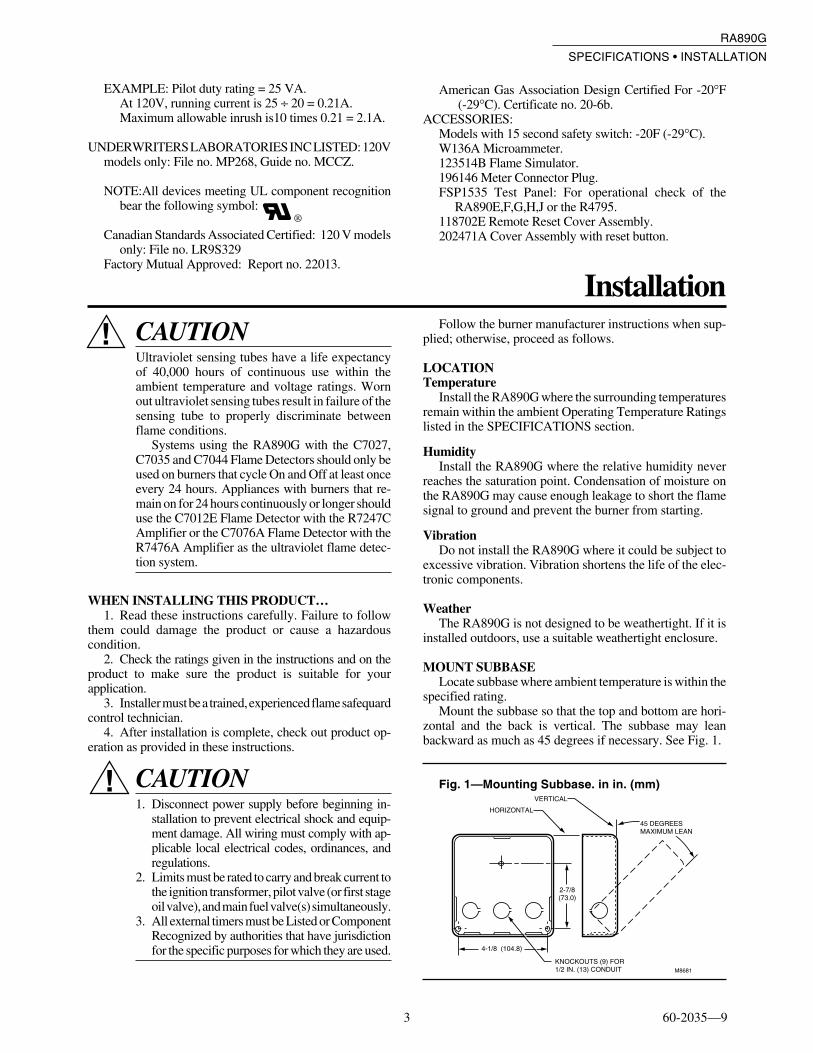
zontal and the back is vertical. The subbase may leanbackward as much as 45 degrees if necessary. See Fig. 1.
Fig. 1—Mounting Subbase. in in. (mm)
M8681
HORIZONTAL
VERTICAL
2-7/8(73.0)
4-1/8 (104.8)
KNOCKOUTS (9) FOR1/2 IN. (13) CONDUIT
45 DEGREESMAXIMUM LEAN
EXAMPLE: Pilot duty rating = 25 VA.At 120V, running current is 25 ÷ 20 = 0.21A.Maximum allowable inrush is10 times 0.21 = 2.1A.
UNDERWRITERS LABORATORIES INC LISTED: 120Vmodels only: File no. MP268, Guide no. MCCZ.
NOTE:All devices meeting UL component recognitionbear the following symbol:
Canadian Standards Associated Certified: 120 V modelsonly: File no. LR9S329
Factory Mutual Approved: Report no. 22013.

60-2035—9 4
RA890G
INSTALLATION
WIRING THE SUBBASE
IMPORTANT: When connecting wire to screw terminal ofterminal strip, wrap wire at least 3/4 of distancearound screw without overlapping. With appropri-ately sized screwdriver, tighten screw until wire issnugly in contact with underside of screw and contactplate. Tighten screw additional one-half turn. Do notuse push-type ratchet screwdriver.
M8717
YES NO NO NO NO
1. All wiring must comply with applicable electricalcodes, ordinances, and regulations. Use NEC Class 1 wiring.
2. For normal installations, use moisture-resistantNo. 14 wire (rated for 167°F (75°C) or higher required byUnderwriters Laboratories Inc).
3. For high temperature installations, use moisture-re-sistant No. 14 wire selected for a temperature rating abovethe maximum operating temperature for all but the ignitionand flame detector F leadwires.
a. For the ignition, use Honeywell Specification no.R1061012 Ignition Cable or equivalent. (This wire israted at 350°F (175°C) for continuous duty, and up to500°F (260°C) for intermittent use. It was tested to25,000 volts.)
b. For the flame detector F leadwire, use HoneywellSpecification no. R1298020 or equivalent. (This wireis rated up to 400°F (205°C) for continuous duty. It istested for operation up to 600 volts and breakdown upto 7500 volts.)
4. For ignition installations in a contaminating environ-ment, use Honeywell Specification no. R1239001 HighTension Ignition Cable or equivalent. This wire is veryresistant to severe conditions of oil, heat, and corona, and istested to withstand high voltages up to 25,000V rms in a saltbath for one minute without breakdown. It is rated at 200°F(93°C) for continuous duty, and up to 350°F (175°C) forintermittent use.
IMPORTANT: Do not run high voltage ignition trans-former wires in the same conduit with the flamedetector wiring.
5. Refer to Fig. 2 and 3 for typical field wiring connec-tions. Follow the burner manufacturer’s wiring diagram ifprovided.
Fig. 2—Gas system with interrupted ignition.
APPLICATIONSEither a line or low voltage controller can be used. If a
line voltage controller is used, connect it between the limitcontrol and terminal 6, and jumper T-T.
Refer to the appropriate flame detector instructions whenparalleling two flame detectors.
IMPORTANT: The C7027, C7035 and C7044 Flame De-tector leads are color coded blue and white. The bluelead must be connected to the F terminal and the whitelead to the G terminal. The circuit is dc and the UVtube is polarity sensitive. Reversing the leads, evenmomentarily, can damage or destroy the UV tube.
All wiring must be NEC Class 1 and conform to localelectrical codes, ordinances, and regulations. If the leadwiresare not long enough to reach the flame safeguard control,splices must be made in a junction box.
M8718
L1 (HOT)
L2
1
2
3
4
3
3
2
4
4
1
FOR INTERMITTENT IGNITION, CONNECT TO TERMINAL 3.
ALARM TERMINALS OPTIONAL. IF LINE VOLTAGE ALARM IS USED.RA890G MUST BE MOUNTED IN SUITABLE ENCLOSURE. ALARM TERMINALS ARE ENERGIZED THROUGH THE RA890 SAFETY SWITCH.ALARM IS NOT SOUNDED UNTIL THE SAFETY SWITCH TRIPS OUT.
PROVIDE DISCONNECT MEANS AND OVERLOAD PROTECTION AS REQUIRED.
MAY USE LINE OR LOW VOLTAGE CONTROLLER. IF LINE VOLTAGE CONTROLLER IS USED, CONNECT IT BETWEEN THE LIMIT CONTROLAND TERMINAL 6. JUMPER T-T.
LINE VOLTAGECONTROLLER
MAIN GASVALVE
IGNITIONTRANSFORMER
PILOTGAS VALVE
LOW VOLTAGECONTROLLER
BLUE
WHITE
6
T
T
F
G 2
2
1
3
4
5
DISCONNECTSWITCH
LINE ORLOW VOLTAGENO ALARM
NC NO COM
USE TERMINALS NC AND C FOR NORMALLYCLOSED ALARMINDICATOR ORINTERBLOCKCIRCUIT IF DESIRED.
LINE OR LOW VOLTAGEALARM POWER SUPPLY
POWERSUPPLY
RA890G
MANUAL OR AUTO RESET LOCKOUT LIMIT CONTROL

5 60-2035—9
RA890G
INSTALLATION • OPERATION AND CHECKOUT
Fig. 3—Oil-Fired system with interruptedignition.
The use of manual reset limits is desirable with theRA890G to prevent the system from cycling off the highlimit and to assure that the condition that causes the limita-tion is detected as soon as possible.
MOUNT RA890GCheck that the power is Off.Remove relay cover and position the RA890G over the
Q270A Universal Mounting Base. See Fig. 4. Start all tenmounting screws and tighten uniformly. These screws com-plete electrical circuits and hold the RA890G to the subbase.
As shipped from the factory, the RA890G is suitable foruse with interrupted or intermittent systems.
Fig. 4—RA890G and Q270A Subbase.
TERMINAL BLOCKS
RA890GBASE
FLAME CURRENTTEST JACK
RA890GCOVER
THUMBSCREW
RESET PUSHBUTTON
LOAD RELAY (1K)
Q270AUNIVERSAL SUBBASE
M8720
TRANSFORMER TR2
TRANSFORMER TR1
FLAME RELAY (2K)
SAFETYSWITCH
M8719
L1 (HOT)
L2
1
2
3
4
3
2
4
4
1
FOR INTERMITTENT IGNITION,CONNECT TO TERMINAL 3.
ALARM TERMINALS OPTIONAL.
PROVIDE DISCONNECT MEANS AND OVERLOAD PROTECTION AS REQUIRED.
MAY USE LINE OR LOW VOLTAGE CONTROLLER. IF LINE VOLTAGE CONTROLLER IS USED, CONNECT IT BETWEEN THE LIMIT CONTROLAND TERMINAL 6. JUMPER T-T.
LINE VOLTAGECONTROLLER
IGNITIONTRANSFORMER
PILOTGAS VALVE
LOW VOLTAGECONTROLLER
BLUE
WHITE
6
T
T
F
G 2
2
1
3
4
5
DISCONNECTSWITCH
POWERSUPPLY
RA890G
MANUAL OR AUTO RESET LOCKOUT LIMIT CONTROL
SECOND STAGEOIL VALVE(IF USED)
OIL VALVE
Operation And Checkout
CAUTION1. Use extreme care while testing the RA890G;
line voltage is present on some terminals andcontacts when power is On.
2. Disconnect power supply before removingcover, removing RA890G from subbase, orreinstalling RA890G onto subbase.
PRELIMINARY CHECKSBefore placing the system in operation, complete the
following preliminary checks:1. Check wiring. Use a meter to check the continuity of
all circuits.2. Check flame detector installation.3. Check burner adjustments.4. Thoroughly purge gas piping.5. Reset the safety switch by pushing in and then releas-
ing the purple safety switch button.
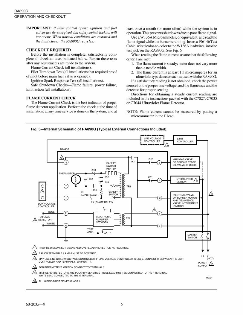
NORMAL OPERATION SUMMARYRefer to Fig. 5 for the internal schematic of the control.1. Call for heat—Load relay pulls in after a slight delay
(flame relay must be out), ignition starts, pilot valve orburner motor is powered. Safety switch heats. A safetyshutdown occurs if a flame or flame simulating condition isdetected at startup.
2. Flame proved—Flame relay pulls in, safety switchheater is de-energized, main valve is powered, ignition is cutoff (if used for interrupted ignition).
3. Call for heat satisfied—Load relay drops out, fuelvalves close, burner motor stops, and flame relay drops out.
NOTE: The pull-in of the load relay is delayed by a ther-mistor with a nominal delay time of 3 to 5 seconds. Thethermistor is affected by ambient temperature. The delaytime may be as little as two seconds when the ambienttemperature is high, or as long as 30 seconds when theambient temperature is low. As the thermistor warms up,the 1K relay may hum slightly before it pulls in. This isnormal.
60-2035—9 6
RA890G
OPERATION AND CHECKOUT
IMPORTANT: If limit control opens, ignition and fuelvalves are de-energized, but safety switch lockout willnot occur. When normal conditions are restored andthe limit closes, the RA890G recycles.
CHECKOUT REQUIREDBefore the installation is complete, satisfactorily com-
plete all checkout tests indicated below. Repeat these testsafter any adjustments are made to the system.
Flame Current Check (all installations).Pilot Turndown Test (all installations that required proof
of pilot before main fuel valve is opened).Ignition Spark Response Test (all installations).Safe Shutdown Checks—Flame failure, power failure,
limit action (all installations).
FLAME CURRENT CHECKThe Flame Current Check is the best indicator of proper
flame detector application. Perform the check at the time ofinstallation, at any time service is done on the system, and at
least once a month (or more often) while the system is inoperation. This prevents shutdowns due to poor flame signal.
Use a W136A Microammeter, or equivalent, and read theflame signal while the burner is running. Insert a 196146 TestCable, wired color-to-color to the W136A leadwires, into thetest jack on the RA890G. See Fig. 6.
When reading the flame current, assure that the followingcriteria are met:
1. The flame current is steady; meter does not vary morethan a needle width.
2. The flame current is at least 1.5 microamperes for anultraviolet type detector such as used with the RA890G.
If a satisfactory reading is not obtained, check the powersource for the proper line voltage, and the flame size and thedetector for proper sensing.
Directions for obtaining a steady current reading areincluded in the instructions packed with the C7027, C7035or C7044 Ultraviolet Flame Detector.
NOTE: Flame current cannot be measured by putting amicroammeter in the F lead.
Fig. 5—Internal Schematic of RA890G (Typical External Connections Included).
L1 (HOT)
L2
2
5
1
2
6
4
3
3
1
2
3
4
5
6
PROVIDE DISCONNECT MEANS AND OVERLOAD PROTECTION AS REQUIRED.
RA890G TERMINALS 1 AND 6 MUST BE POWERED.
MAY USE LINE OR LOW VOLTAGE CONTROLLER. IF LINE VOLTAGE CONTROLLER IS USED, CONNECT IT BETWEEN THE LIMITCONTROLLER NAD TERMINAL 6. JUMPER T-T.
FOR INTERMITTENT IGNITION CONNECT TO TERMINAL 3.
MINIPEEPER DETECTORS ARE POLARITY SENSITIVE—BLUE LEAD MUST BE CONNECTED TO THE F TERMINAL; WHITE LEAD CONNECTED TO THE G TERMINAL.
ALL WIRING MUST BE NEC CLASS 1.
LOW VOLTAGECONTROLLER
TO FLAME DETECTOR
THERMISTOR
1K (LOAD RELAY)
2K (FLAME RELAY)
ELECTRONICAMPLIFIERNETWORK
LINE VOLTAGECONTROLLER
LIMITCONTROLLER
MAIN GAS VALVEOR SECOND STAGEOIL VALVE (IF USED)
INTERRUPTEDIGNITION
PILOT GAS VALVE,OR BURNER MOTORAND DELAYED OILVALVE; INTERMITENTIGNITION
MASTERSWITCH
POWER SUPPLY
TESTJACK
TR2
SAFETYSWITCH
2K3
1K22K4
SAFETYSWITCHHEATER
1K1
TR1
2K2
2K1
M8721
5
4
3
1
2G
F
T
T
6
BLUE
WHITE
1K3
1K4
RA890G

7 60-2035—9
RA890G
OPERATION AND CHECKOUT
Fig. 6—Flame current check.
M8716
W136A
196146 METER CONNECTOR PLUG (SUPPLIED WITH W136)
BLACK
BLACK
RED
RED
FLAMECURRENTTEST JACK
RA890
PILOT TURNDOWN TEST
CAUTIONThe pilot turndown test should be performed onlyby qualified personnel, and the instructions shouldbe followed carefully.
On systems that prove a pilot before the main fuel valvecan be opened, perform a pilot turndown test to prove that themain burner can be lighted by the smallest pilot that will holdin the flame relay. Perform a flame current check before andafter the pilot turndown test.
1. Open the main power switch.2. Shut off the fuel supply to the main burner only by
closing the manual main burner shutoff cock. Do not shut offthe fuel supply to the pilot valve.
3. Restore power to the relay.4. Start the system by raising the setpoint of the control-
ler (or pressing the START button). The pilot will light andpull in the flame relay.
5. Reduce the size of the pilot flame to the turndowncondition by slowly closing the manual valve on the pilot gasline. At the turndown condition, the pilot will be smallenough to just barely hold in the flame relay (2K).
a. Turn down the pilot until relay 2K drops out.b. Turn the pilot back up slowly just until relay 2K pulls
back in.c. Again turn the pilot down slightly, but not enough so
the relay drops out.If the relay drops out again, simply turn up the pilot and
try again. The closer the pilot is to the dropout condition, themore conclusive the test will be.
6. Check that the pilot is lit and relay 2K is pulled in.7. Open the manual main burner shutoff cock. Main
flame should light smoothly within one second. If the burnerdoes not light within one second, close the shutoff cock andshut off power to the relay. Proceed to step 9.
8. If the burner lights, repeat step 7 two or three times toverify smooth lightoff.
9. If the lightoff is unsatisfactory, readjust the flamedetector to require a larger pilot flame to hold in the flame
relay. This usually requires resighting the detector fartherout on the axis of the pilot flame.
CAUTIONIf the pilot needs to be adjusted and rechecked,allow five minutes for the purge of unburned gasesin the firebox before proceeding to the next step.
10. Repeat the entire turndown test until the flame isestablished promptly in step 7.
11. Turn up the pilot to full flame at the completion of thetest. Perform a flame current check before leaving the job.
IGNITION SPARK RESPONSE TESTThe flame detection system should not respond to the
ignition spark (no meter movement). To determine flamedetector sensitivity to ignition spark, perform the followingsteps:
1. Shut off pilot and main fuel manual valves.2. Connect a W136 Microammeter and 196146 Test
Cable into the test jack on the RA890G. (See Flame Currentcheck procedure section.)
3. Raise the controller setpoint. This should energize theignition transformer and produce an ignition spark.
4. The W136 Meter should not indicate a signal present.5. If the meter indicates UV is being detected, resight the
flame detector until the UV signal is eliminated. It may benecessary to construct a barrier to block the ignition sparkfrom the detector view. Continue adjusting until the ignitionspark flame signal is less than one-fourth microampere.
NOTE: The Honeywell Q624A Solid State Spark Generatorprevents detection of ignition spark when properly ap-plied with flame detection systems using C7027, C7035,or C7044 Minipeeper Ultraviolet Flame Detectors. TheQ624A is for use only with gas pilots.
SAFE SHUTDOWN CHECKS LIMIT ACTIONWith the burner operating, lower the high limit setting to
simulate an overheated boiler or furnace. Normal shutdownshould occur. Restore the normal limit setting; the burnershould restart.
FLAME FAILURE RESPONSE TESTWith the burner operating for a period of five minutes,
close the manual fuel valves to simulate a flame failure. TheW136 Meter reading should drop to zero within the flameresponse timing of the flame safeguard relay (0.8 to 3 sec-onds nominal). This action should be followed by safetyswitch lockout (15 seconds nominal). After the safety switchcools, open the manual valves. The burner should restartwhen the safety switch is reset.
If the meter reading does not drop to zero within theallowed time, replace the UV detector and repeat the test.
IMPORTANT: Repeat ALL required checkout tests afterall adjustments are complete. ALL tests must be satis-fied with the flame detector in its FINAL position.
60-2035—9 8
RA890G
OPERATION AND CHECKOUT • SERVICE
POWER FAILUREWith the burner operating, open and then immediately
close the line switch to simulate a power failure. Burnershould shut down. After a short delay for component check,burner should restart and operate normally.
FLAME DURING STARTThe RA90G should shut down on safety during start-up if
a flame or flame simulating condition is detected. Insert123514B flame simulator into the test jack. Start the systemby raising the controller setpoint or pressing the start button.
Hold the simulator on terminal F; the flame relay should pullin and system should lock out within the safety switchtiming. Remove the simulator and reset the safety switchafter it cools.
NOTE: At the completion of all Checkout tests, make surethat the RA890 is not on safety lockout, the pilot is turnedup to its normal level, and all limit settings are correct.Operate the system through one normal cycle beforeleaving the installation.
Service
CAUTION1. Only a trained, experienced, flame safeguard
control technician should attempt to service orrepair heating equipment or controls.
2. Under certain conditions, a capacitor betweenterminals F and G within RA890G can remaincharged even after the power is disconnectedand the device is removed from the mountingbase. TO AVOID THE HAZARD OF ELEC-TRICAL SHOCK, ALWAYS USE A SCREW-DRIVER WITH AN INSULATED HANDLEAND AVOID TOUCHING THE F AND GTERMINALS.
3. Never manually push in the RA890 Relays.
GENERAL1. Repeat all checks required in the Checkout section
when replacing any system component, or when relightingor restoring power to the system after an extended shutdownperiod.
2. The captive mounting screws carry current; alwaysdisconnect power before loosening or tightening the mount-ing screws.
3. On each service call, check the controller for theapproximately correct calibration and differential; assurethat it is mounted securely (see controller instructions).
4. Never use oil on any part of the RA890G.5. When cleaning the burner, clean the flame detector
lens.6. DO NOT MANUALLY PUSH IN THE RA890 RE-
LAYS. This may damage the relays and it is an unsafepractice because it overrides the protective features of therelay. Clean relay contacts only as instructed below.
PERIODIC MAINTENANCEThe specific maintenance schedule setup depends on
several factors including type of equipment being controlled,operating conditions (dirt and heat especially), cost of anuisance shutdown, etc. Include the following in any main-tenance program:
1. Perform a Flame Failure Check and Pilot TurndownTest whenever the burner is serviced, and at least annually.
2. Inspect and clean the detector and any viewing win-dows as often as required by soot accumulation and heatconditions at the detector.
3. Perform a Flame Current Check at least monthly, andmore often when a shutdown may be costly.
4. Clean contacts only when required by failure to oper-ate properly.
CONTACT CLEANING
CAUTIONOpen the master switch before removing the relayover or before cleaning contacts. Line voltage maybe present on most contacts when power is on.
Field cleaning of relay or timer contacts is not recom-mended. If they must be cleaned, use only Honeywellpressurized Contact Cleaner part no. 132569. Honeywell’schemical analysis laboratory recommends only this cleaner.Directions for using the cleaner are printed on the can.
IMPORTANT:1. Do not clean contacts unless absolutely necessary.2. Use only Honeywell Contact Cleaner part no. 132569.
Do not use any other type of contact cleaner.3. Use extreme care to avoid bending the contacts or
changing the specifications or configuration in anyway.
4. Do not use abrasive material to clean contacts.5. Do not use hard paper such as a business card to clean
the contacts.
Do not use other types of contact cleaners. Honeywell’schemical analysis laboratory tested other pressurized typecontact cleaners but did not approve them for these reasons:
1. The solvents could deteriorate plastic parts and wireinsulation.
2. The cleaners have an oily residue that collects dust anddirt. The residue breaks down to form various carbonaceousproducts. Either result causes early contact failure.
Do not use an abrasive (burnishing tool, sandpaper, stick,file, etc.) to clean contacts because it can cause early contactfailure for these reasons:
9 60-2035—9
RA890G
SERVICE • TROUBLESHOOTING
1. Some relay and time contacts are plated with gold forincreased reliability. Burnishing can quickly remove theplating.
2. The radii or points of the contacts are designed withspecific shapes to best serve the intended functions of thecontacts. Burnishing can rapidly alter contact configurations.
3. Using an abrasive loosens fine particles of the contactmaterial that adhere to the surface of the contact and increaseits resistance.
4. Contact specifications (contact pressures, pressback,and gaps) are carefully controlled during manufacturing toassure maximum contact life. Burnishing can easily changethese specifications.
Troubleshooting
CAUTION1. Use extreme care while troubleshooting the
RA890G; line voltage is present on some termi-nals and contacts when power is on.
2. Disconnect the power supply before removingthe cover, cleaning contacts, removing theRA890G from the subbase, or reinstalling theRA890G on the subbase.
When trouble occurs in the heating system and its cause isnot immediately apparent, the serviceman can apply thefollowing step-by-step checkout to locate the cause of mostproblems.
TEST STANDBY OPERATION1. Set controller not to call for heat (decrease setpoint).2. Reset the safety switch by pushing in and then releas-
ing the purple safety switch reset button.3. Close the line switch.4. Check for line voltage between terminals 6 and 2, and
between 1 and 2. (Voltage will be zero at terminal 6 if a linevoltage controller is used; check for line voltage whencontroller is set to call for heat.)
a. Voltage must be within +10 to -15 percent of the ratedvoltage.
b. If voltage is zero, check the power supply line forblown fuses, open circuit, or open disconnect switch.Check limit contacts for continuity.
5. Check position of flame relay. (If a line voltage con-troller is used, observe the action of the flame relay on a callfor heat.)
a. If the flame relay is out, proceed to step 6.b. If the flame relay is pulled in, check for a flame
simulating condition.1) Insert 123514B Flame Simulator Plug into test
jack; touch the other end to the F terminal of theRA890G.
2) If flame relay holds in, replace the RA890.3) If flame relay drops out, trouble is in the flame
detector or external circuit. Replace the detector.
TEST STARTING OPERATION6. Set controller to call for heat (increase setpoint).7. Observe load relay for pull-in.a. Load relay pulls in to light pilot and start burner;
proceed to step 11.b. Load relay does not pull in; proceed to step 8.
c. Load relay pulls in but does not light or burner does notstart; proceed to step 10.
8. Check line voltage controller, if used, and check thelimit; if the load relay does not pull in, check again for powerat terminal 6 with the controller calling for heat. If there ispower at terminal 6 and a line voltage controller is used,clean all relay contacts. Replace the RA890 if the relay stilldoes not pull in. If a low voltage controller is used, proceedto step 9.
9. Check the low voltage controller, if used, by jumpingT-T.
a. Load relay pulls in with T-T jumpered; check control-ler and external circuit.
b. Load relay does not pull in with T-T jumpered; cleanall relay contacts. Replace the RA890 if the load relaystill does not pull in.
10. If the load relay pulls in but the pilot will not light orthe burner will not start, check voltage at terminals 3-2 or 4-2.
a. If no voltage at terminals 3-2 or 4-2; clean the relaycontacts. Replace the RA890 if trouble cannot becorrected.
b. If normal line voltage at terminals 3-2 or 4-2, checkexternal burner, ignition, and valve circuits. Checkwiring, burner adjustment, ignition systems includingelectrode spacing and location, oil quality, characterand efficiency of oil atomization, fuel supply pressure,flame pattern, flame character and quality, pilot loca-tion with respect to main burner, flame detector, orother conditions that may delay lightoff.
TESTING FLAME DETECTING FUNCTION11. Observe the flame relay (right relay) for pull-in when
flame is established.a. Flame relay pulls in; proceed to step 13.b. Flame relay does not pull in; proceed to step 12.
12. Check the flame relay with a 123514B Flame Simula-tor, if available (follow the instructions with the simulator),or check the following:
a. Perform a Flame Current Check (see Flame CurrentCheck section).
b. If the current is satisfactory, replace the RA890.c. If the current is not satisfactory, consult the instruc-
tions packed with the flame detector.
OBSERVE SEQUENCING OPERATION13. Observe the second stage oil valve or main gas valve
for opening when flame relay pulls in.a. If valve does not open, check for line voltage at
terminals 2-5.

60-2035—9 10
RA890G
TROUBLESHOOTING
1) Normal voltage—check valve and valve circuit.2) Zero voltage—clean relay contacts. Replace the
RA890 if this does not correct problem.14. Observe ignition for cutoff when flame relay pulls in if
connected to terminal 4.a. If ignition stays on and wiring checks out, replace the
RA890.
MISCELLANEOUS PROBLEMSRelay Chatter
Load relay chatter may result from extreme low voltage(notify power company) or from a loose connection (tighten).
Flame relay chatter may result from improper combus-tion (adjust burner), or soot or carbon on flame detector(clean and correct the cause).
REPEATED LOCKOUTS OR CONTROLFAILURES
The most common causes of repeated failure of thiscontrol or flame detector or of repeated lockouts are:
a. High ambient temperatures—over 125°F (52°C).b. Supply voltage variation greater than +10 to -15 percent.c. Electrical overloading of the contacts.d. Marginal flame current.e. Frequent cycling with high ambient temperatures.

11 60-2035—9

Home and Building Control Home and Building ControlHoneywell International, Inc. Honeywell Limited—Honeywell Limitée1985 Douglas Drive North 35 Dynamic DriveGolden Valley, MN 55422 Scarborough, Ontario
M1V 4Z9