r1200gs odyssey luggage installation guide
TRANSCRIPT
Xplorermoto [email protected] 520-743-0638 www.xplorermoto.com Instructions Created by JVB Productions 2010 © www.jimvonbaden.com
R1200GS Odyssey Luggage Installation Guide Thank you for purchasing Jesse Luggage for your Motorcycle. Our Luggage, handcrafted in the USA, is designed for those with an interest in finding the most durable and functional luggage for their adventure touring. Al Jesse has been designing and building aluminum touring luggage since 1991. He has traveled to over 40 countries on his own motorcycle and knows what it takes to make a good set of luggage. Jesse Luggage has built in several unusual features, including hinged lids that no only hold stuff while you are unloading, but also serve as additional packing space. The angle provides extra strength as well as clearance in corners and for your heels when paddling in deep sand. Powder coating provides a durable finished look for your boxes. We hope you enjoy your luggage for years to come. Tools Required Tools required are listed at the beginning of each section, however here is a list of tools for the entire job: Sockets: 8mm, 10mm, 15mm deep, 13mm deep Torx: T45, T-30, T-25 Allen: 4mm, 5mm, 6mm, 3/32” and 3/16” (provided) Wrenches: 13mm, 10mm Screwdrivers: Phillips, small standard Other: Wire Cutters General Instructions: Do not tighten any bolt until the entire assembly is completed. Leave all bolts completely loose until every component is in place loosely. Once the components have been installed, tighten all bolts snugly starting from the front and working back. Note where there are gaps in the assembly, and add spacers as necessary. After the whole system has been snugly bolted down, and any adjustments made, remove one bolt at a time and use blue Loc-Tite ©, two drops per bolt, and fully tighten each bolt. Note; do not apply Loc-Tite © to any nut which is a self-locking nut. Note: The hardware for most parts is wrapped in place where it belongs, and in the order it needs to be installed. DO NOT remove the wrap until ready to install that particular piece. This helps keep track of what bolts go with what part.
Xplorermoto [email protected] 520-743-0638 www.xplorermoto.com Instructions Created by JVB Productions 2010 © www.jimvonbaden.com
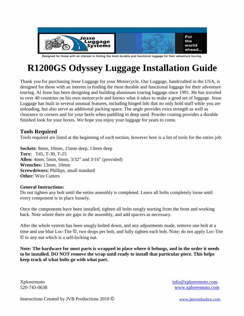
Make sure all components are included with your kit. Most hardware is attached to the proper components. See photo above. Note: The low pipe kit has slightly different left and center mounts. Step 1: Installing the Muffler Lowering Kit
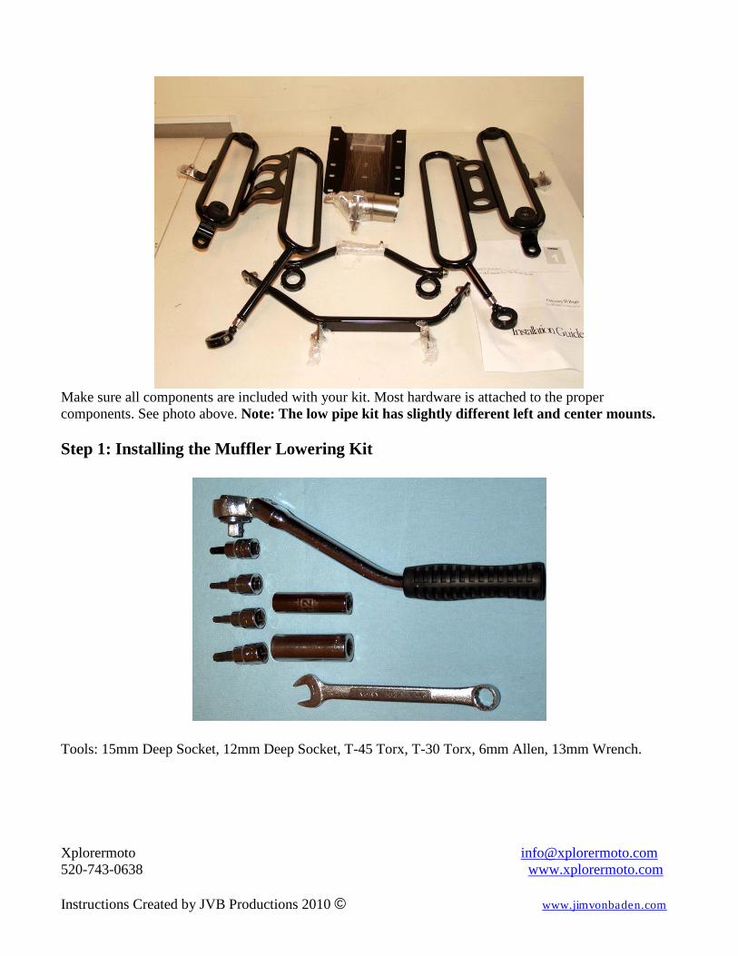
Tools: 15mm Deep Socket, 12mm Deep Socket, T-45 Torx, T-30 Torx, 6mm Allen, 13mm Wrench.
Xplorermoto [email protected] 520-743-0638 www.xplorermoto.com Instructions Created by JVB Productions 2010 © www.jimvonbaden.com
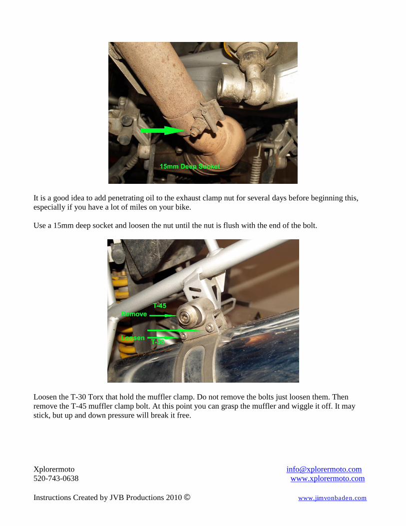
It is a good idea to add penetrating oil to the exhaust clamp nut for several days before beginning this, especially if you have a lot of miles on your bike. Use a 15mm deep socket and loosen the nut until the nut is flush with the end of the bolt.
Loosen the T-30 Torx that hold the muffler clamp. Do not remove the bolts just loosen them. Then remove the T-45 muffler clamp bolt. At this point you can grasp the muffler and wiggle it off. It may stick, but up and down pressure will break it free.
Xplorermoto [email protected] 520-743-0638 www.xplorermoto.com Instructions Created by JVB Productions 2010 © www.jimvonbaden.com
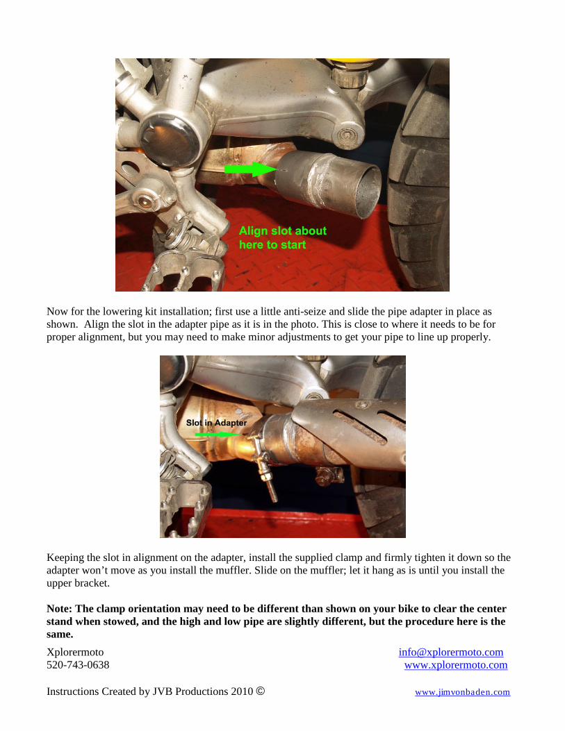
Now for the lowering kit installation; first use a little anti-seize and slide the pipe adapter in place as shown. Align the slot in the adapter pipe as it is in the photo. This is close to where it needs to be for proper alignment, but you may need to make minor adjustments to get your pipe to line up properly.
Keeping the slot in alignment on the adapter, install the supplied clamp and firmly tighten it down so the adapter won’t move as you install the muffler. Slide on the muffler; let it hang as is until you install the upper bracket. Note: The clamp orientation may need to be different than shown on your bike to clear the center stand when stowed, and the high and low pipe are slightly different, but the procedure here is the same.
Xplorermoto [email protected] 520-743-0638 www.xplorermoto.com Instructions Created by JVB Productions 2010 © www.jimvonbaden.com
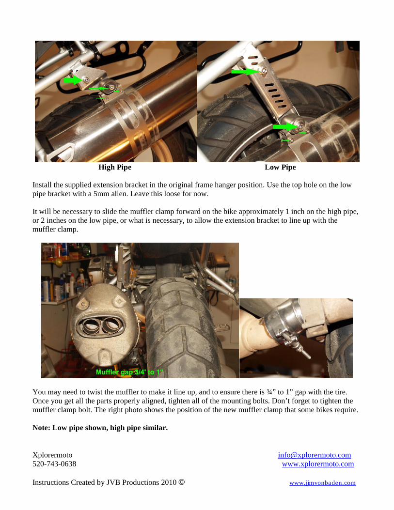
High Pipe Low Pipe
Install the supplied extension bracket in the original frame hanger position. Use the top hole on the low pipe bracket with a 5mm allen. Leave this loose for now. It will be necessary to slide the muffler clamp forward on the bike approximately 1 inch on the high pipe, or 2 inches on the low pipe, or what is necessary, to allow the extension bracket to line up with the muffler clamp.
You may need to twist the muffler to make it line up, and to ensure there is ¾” to 1” gap with the tire. Once you get all the parts properly aligned, tighten all of the mounting bolts. Don’t forget to tighten the muffler clamp bolt. The right photo shows the position of the new muffler clamp that some bikes require. Note: Low pipe shown, high pipe similar.
Xplorermoto [email protected] 520-743-0638 www.xplorermoto.com Instructions Created by JVB Productions 2010 © www.jimvonbaden.com
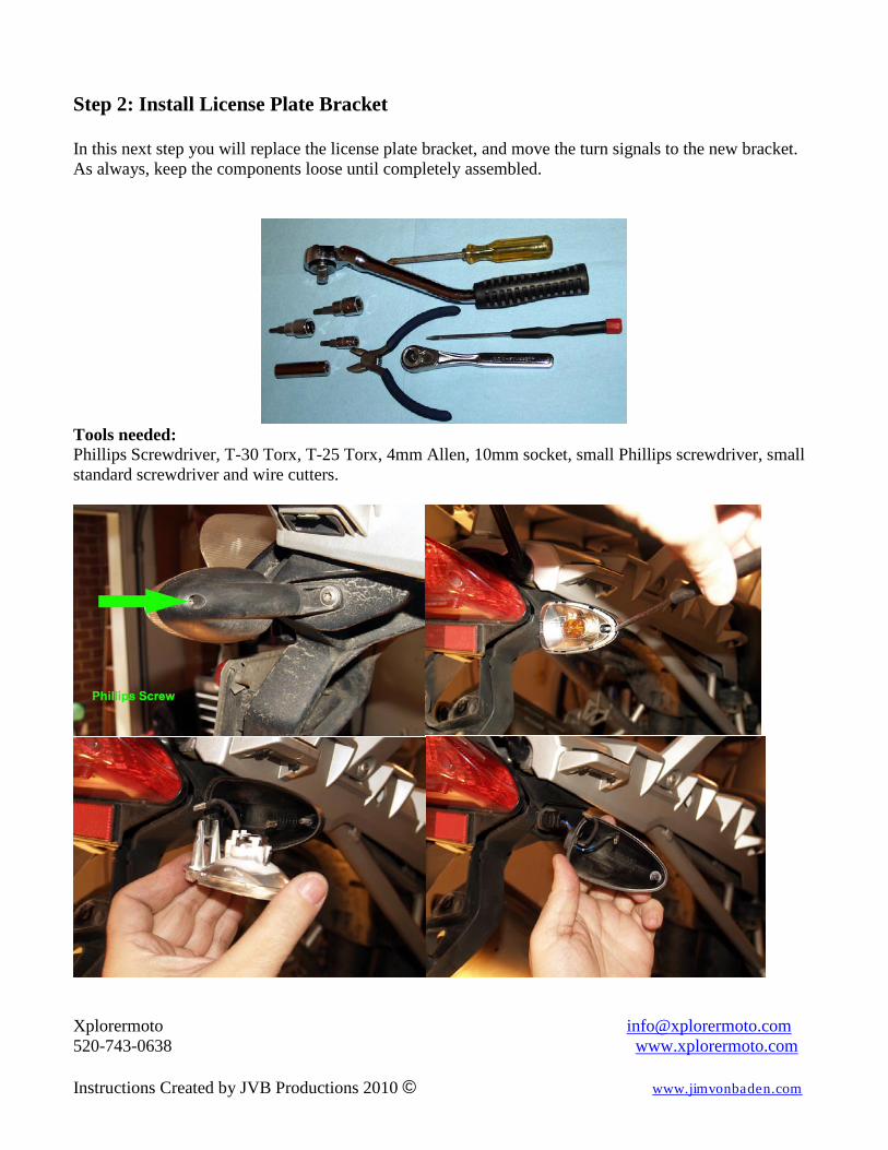
Step 2: Install License Plate Bracket In this next step you will replace the license plate bracket, and move the turn signals to the new bracket. As always, keep the components loose until completely assembled.
Tools needed: Phillips Screwdriver, T-30 Torx, T-25 Torx, 4mm Allen, 10mm socket, small Phillips screwdriver, small standard screwdriver and wire cutters.
Xplorermoto [email protected] 520-743-0638 www.xplorermoto.com Instructions Created by JVB Productions 2010 © www.jimvonbaden.com
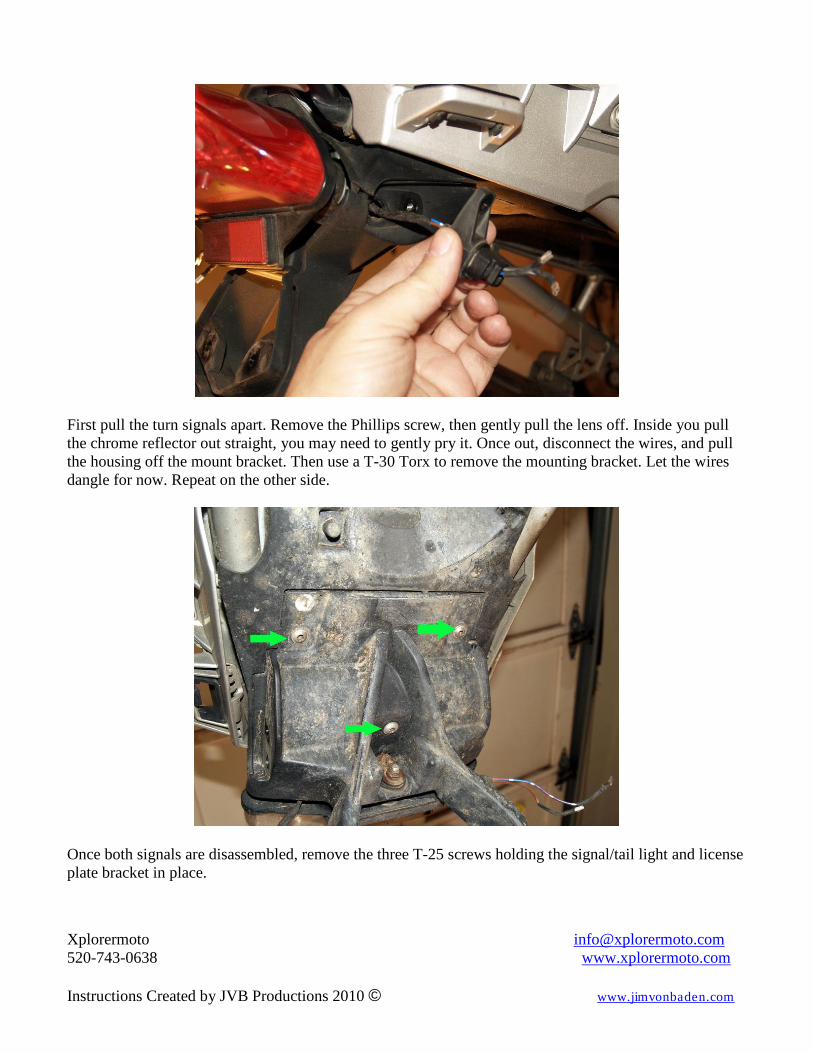
First pull the turn signals apart. Remove the Phillips screw, then gently pull the lens off. Inside you pull the chrome reflector out straight, you may need to gently pry it. Once out, disconnect the wires, and pull the housing off the mount bracket. Then use a T-30 Torx to remove the mounting bracket. Let the wires dangle for now. Repeat on the other side.
Once both signals are disassembled, remove the three T-25 screws holding the signal/tail light and license plate bracket in place.
Xplorermoto [email protected] 520-743-0638 www.xplorermoto.com Instructions Created by JVB Productions 2010 © www.jimvonbaden.com
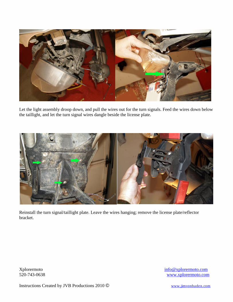
Let the light assembly droop down, and pull the wires out for the turn signals. Feed the wires down below the taillight, and let the turn signal wires dangle beside the license plate.
Reinstall the turn signal/taillight plate. Leave the wires hanging; remove the license plate/reflector bracket.
Xplorermoto [email protected] 520-743-0638 www.xplorermoto.com Instructions Created by JVB Productions 2010 © www.jimvonbaden.com
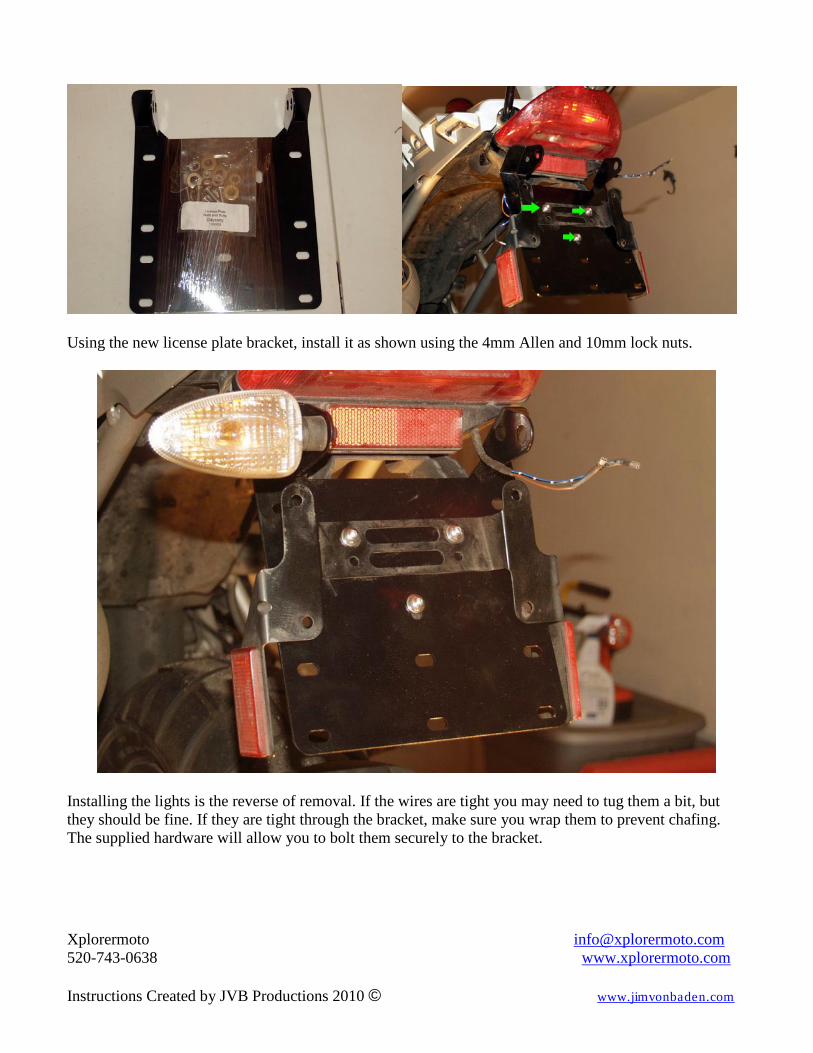
Using the new license plate bracket, install it as shown using the 4mm Allen and 10mm lock nuts.
Installing the lights is the reverse of removal. If the wires are tight you may need to tug them a bit, but they should be fine. If they are tight through the bracket, make sure you wrap them to prevent chafing. The supplied hardware will allow you to bolt them securely to the bracket.
Xplorermoto [email protected] 520-743-0638 www.xplorermoto.com Instructions Created by JVB Productions 2010 © www.jimvonbaden.com
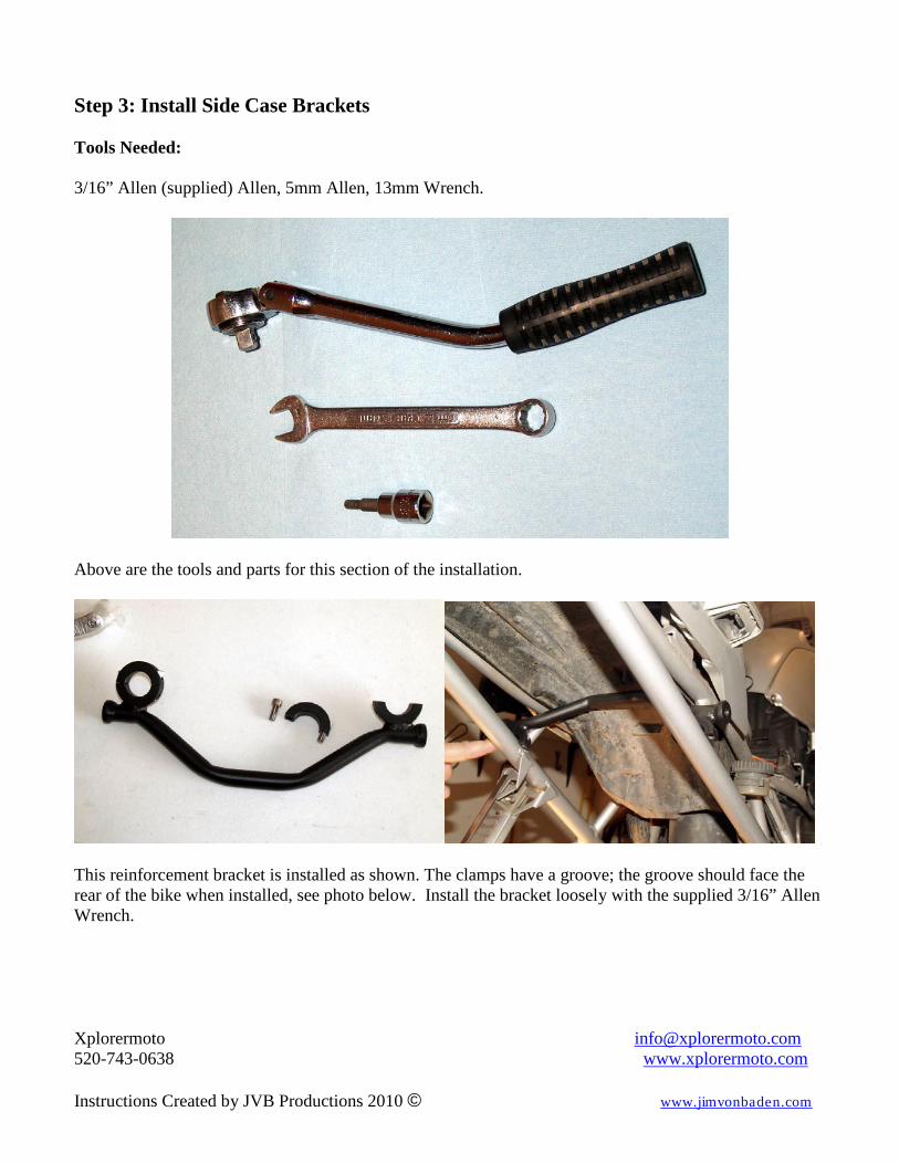
Step 3: Install Side Case Brackets Tools Needed: 3/16” Allen (supplied) Allen, 5mm Allen, 13mm Wrench.
Above are the tools and parts for this section of the installation.
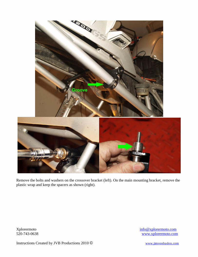
This reinforcement bracket is installed as shown. The clamps have a groove; the groove should face the rear of the bike when installed, see photo below. Install the bracket loosely with the supplied 3/16” Allen Wrench.
Xplorermoto [email protected] 520-743-0638 www.xplorermoto.com Instructions Created by JVB Productions 2010 © www.jimvonbaden.com
Remove the bolts and washers on the crossover bracket (left). On the main mounting bracket, remove the plastic wrap and keep the spacers as shown (right).
Xplorermoto [email protected] 520-743-0638 www.xplorermoto.com Instructions Created by JVB Productions 2010 © www.jimvonbaden.com
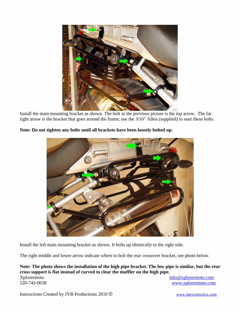
Install the main mounting bracket as shown. The bolt in the previous picture is the top arrow. The far right arrow is the bracket that goes around the frame; use the 3/16” Allen (supplied) to start these bolts. Note: Do not tighten any bolts until all brackets have been loosely bolted up.
Install the left main mounting bracket as shown. It bolts up identically to the right side. The right middle and lower arrow indicate where to bolt the rear crossover bracket, see photo below. Note: The photo shows the installation of the high pipe bracket. The low pipe is similar, but the rear cross support is flat instead of curved to clear the muffler on the high pipe.
Xplorermoto [email protected] 520-743-0638 www.xplorermoto.com Instructions Created by JVB Productions 2010 © www.jimvonbaden.com
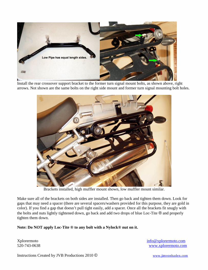
Install the rear crossover support bracket to the former turn signal mount bolts, as shown above, right arrows. Not shown are the same bolts on the right side mount and former turn signal mounting bolt holes.
Brackets installed, high muffler mount shown, low muffler mount similar.
Make sure all of the brackets on both sides are installed. Then go back and tighten them down. Look for gaps that may need a spacer (there are several spacers/washers provided for this purpose, they are gold in color). If you find a gap that doesn’t pull tight easily, add a spacer. Once all the brackets fit snugly with the bolts and nuts lightly tightened down, go back and add two drops of blue Loc-Tite ® and properly tighten them down. Note: Do NOT apply Loc-Tite ® to any bolt with a Nylock® nut on it.
Xplorermoto [email protected] 520-743-0638 www.xplorermoto.com Instructions Created by JVB Productions 2010 © www.jimvonbaden.com
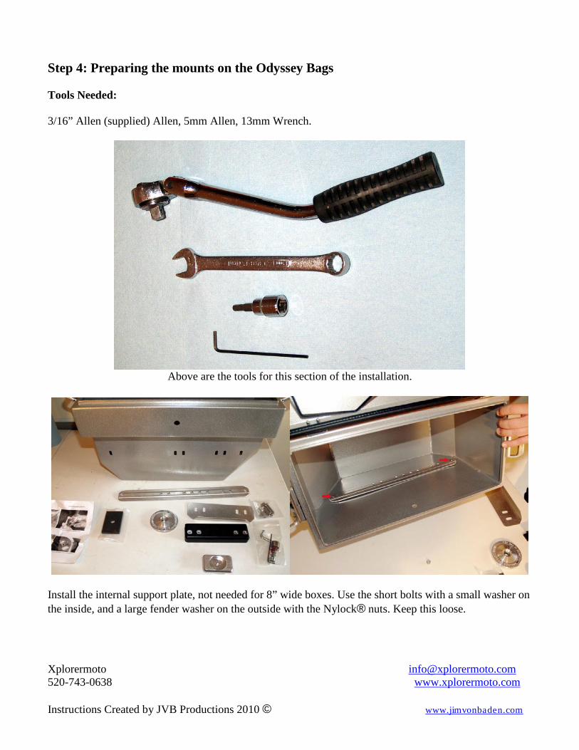
Step 4: Preparing the mounts on the Odyssey Bags Tools Needed: 3/16” Allen (supplied) Allen, 5mm Allen, 13mm Wrench.
Above are the tools for this section of the installation.
Install the internal support plate, not needed for 8” wide boxes. Use the short bolts with a small washer on the inside, and a large fender washer on the outside with the Nylock® nuts. Keep this loose.
Xplorermoto [email protected] 520-743-0638 www.xplorermoto.com Instructions Created by JVB Productions 2010 © www.jimvonbaden.com
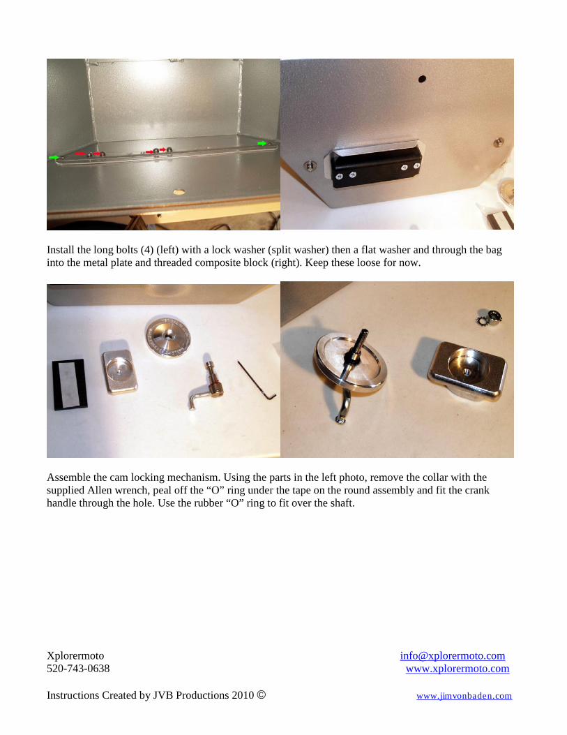
Install the long bolts (4) (left) with a lock washer (split washer) then a flat washer and through the bag into the metal plate and threaded composite block (right). Keep these loose for now.
Assemble the cam locking mechanism. Using the parts in the left photo, remove the collar with the supplied Allen wrench, peal off the “O” ring under the tape on the round assembly and fit the crank handle through the hole. Use the rubber “O” ring to fit over the shaft.
Xplorermoto [email protected] 520-743-0638 www.xplorermoto.com Instructions Created by JVB Productions 2010 © www.jimvonbaden.com
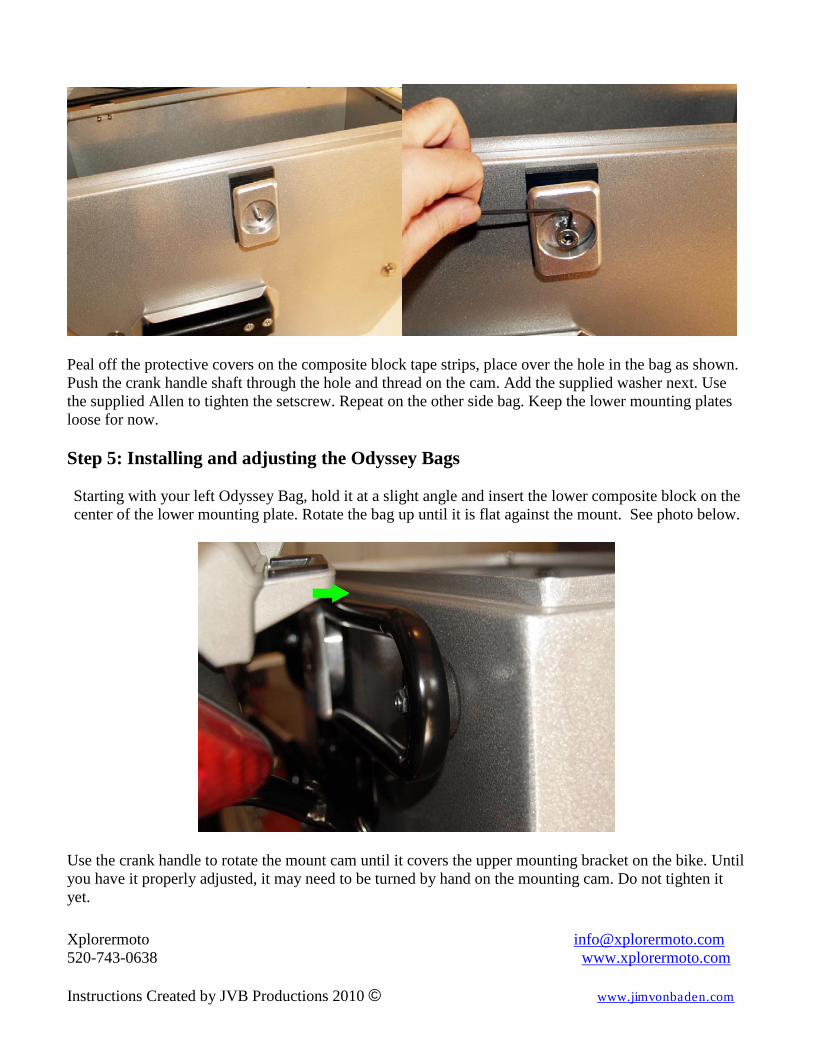
Peal off the protective covers on the composite block tape strips, place over the hole in the bag as shown. Push the crank handle shaft through the hole and thread on the cam. Add the supplied washer next. Use the supplied Allen to tighten the setscrew. Repeat on the other side bag. Keep the lower mounting plates loose for now. Step 5: Installing and adjusting the Odyssey Bags
Starting with your left Odyssey Bag, hold it at a slight angle and insert the lower composite block on the center of the lower mounting plate. Rotate the bag up until it is flat against the mount. See photo below.
Use the crank handle to rotate the mount cam until it covers the upper mounting bracket on the bike. Until you have it properly adjusted, it may need to be turned by hand on the mounting cam. Do not tighten it yet.
Xplorermoto [email protected] 520-743-0638 www.xplorermoto.com Instructions Created by JVB Productions 2010 © www.jimvonbaden.com
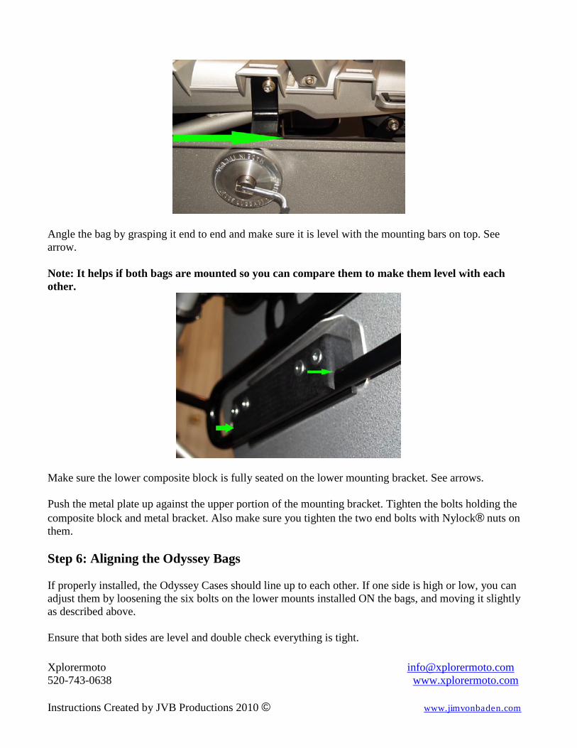
Angle the bag by grasping it end to end and make sure it is level with the mounting bars on top. See arrow. Note: It helps if both bags are mounted so you can compare them to make them level with each other.
Make sure the lower composite block is fully seated on the lower mounting bracket. See arrows. Push the metal plate up against the upper portion of the mounting bracket. Tighten the bolts holding the composite block and metal bracket. Also make sure you tighten the two end bolts with Nylock® nuts on them. Step 6: Aligning the Odyssey Bags If properly installed, the Odyssey Cases should line up to each other. If one side is high or low, you can adjust them by loosening the six bolts on the lower mounts installed ON the bags, and moving it slightly as described above. Ensure that both sides are level and double check everything is tight.

Xplorermoto [email protected] 520-743-0638 www.xplorermoto.com Instructions Created by JVB Productions 2010 © www.jimvonbaden.com
Low Pipe High Pipe
Remember, these bags are designed to be moved on the mounts. They will move as much as 3 inches for and aft. Depending on your needs, you can adjust them to suit. They will need to be completely removed and repositioned for this adjustment.
This photo shows the range of adjustment. Though it is a picture from the R1100/1150 series, the range is the same. Step 6: Go for a Ride Once you have completed the installation of your new Safari Cases, put all your tools away; grab a beer, a map, and start making plans for your next trip, because you and your Jesse Luggage are really going places. If you encounter any issues, please contact Xplorermoto at the e-mail and phone number listed below.