quickstart instructions - phytec · using keil's ulink and the keil microcontroller...
TRANSCRIPT

A product of a PHYTEC Technology Holding company
QuickStart Instructions
KEIL-Kit nanoMODUL-STM32F103
Using Keil's ULINK and the Keil Microcontroller Development Tool Chain
Note: The PHYTEC Kit CD includes the electronic version of the English nanoMODUL-STM32F103 Hardware Manual
Edition: August 2009

nanoMODUL-STM32F103 QuickStart Instructions
© PHYTEC Messtechnik GmbH, Germany 2009 L-739e_2
In this manual are descriptions for copyrighted products that are not explicitly indicated as such. The absence of the trademark (™) and copyright (©) symbols does not imply that a product is not protected. Additionally, registered patents and trademarks are similarly not expressly indicated in this manual. The information in this document has been carefully checked and is believed to be entirely reliable. However, PHYTEC Messtechnik GmbH assumes no responsibility for any inaccuracies. PHYTEC Messtechnik GmbH neither gives any guarantee nor accepts any liability whatsoever for consequential damages resulting from the use of this manual or its associated product. PHYTEC Messtechnik GmbH reserves the right to alter the information contained herein without prior notification and accepts no responsibility for any damages which might result. Additionally, PHYTEC Messtechnik GmbH offers no guarantee nor accepts any liability for damages arising from the improper usage or improper installation of the hardware or software. PHYTEC Messtechnik GmbH further reserves the right to alter the layout and/or design of the hardware without prior notification and accepts no liability for doing so. © Copyright 2009 PHYTEC Messtechnik GmbH, D-55129 Mainz. Rights - including those of translation, reprint, broadcast, photomechanical or similar reproduction and storage or processing in computer systems, in whole or in part - are reserved. No reproduction may be made without the explicit written consent from PHYTEC Messtechnik GmbH. EUROPE NORTH AMERICA
Address: PHYTEC Technologie Holding AG Robert-Koch-Str. 39 D-55129 Mainz GERMANY
PHYTEC America LLC 203 Parfitt Way SW, Suite G100 Bainbridge Island, WA 98110 USA
Ordering Information:
+49 (800) 0749832 [email protected]
1 (800) 278-9913 [email protected]
Technical Support:
+49 (6131) 9221-31 [email protected]
1 (800) 278-9913 [email protected]
Fax: +49 (6131) 9221-33 1 (206) 780-9135
Web Site: http://www.phytec.de http://www.phytec.com 2nd Edition: August 2009

Contents
© PHYTEC Messtechnik GmbH, Germany 2009 L-739e_2
1 Introduction to the Rapid Development Kit............................................... 1
1.1 Rapid Development Kit Documentation ........................................... 1
1.2 Overview of this QuickStart Instruction ............................................ 1
2 System Description .................................................................................. 2
2.1 Hardware Description ....................................................................... 2
2.2 Host System Requirements.............................................................. 2
2.3 The PHYTEC nanoMODUL-STM32F103......................................... 3
2.4 Keil RealView Microcontroller Development Kit ............................... 3
3 Getting Started ......................................................................................... 4
3.1 Installing Rapid Development Kit Software ...................................... 4
3.1.1 Installing Documentation from PHYTEC Kit CD................... 4
3.1.2 Installing Keil Microcontroller Development Tools................ 5
3.2 Interfacing the nanoMODUL-STM32F103 to a Host-PC.................. 6
3.3 Downloading Blinky Example Code with μVision3 ........................... 7
3.3.1 Build the Project.................................................................... 9
3.3.2 Start the Debugger and Download to nanoMODUL ............. 9
4 Debugging .............................................................................................. 11
4.1 Keil µVision3 Debug Features........................................................ 11
4.2 Debugging Modes .......................................................................... 13
4.3 Starting the Debugger .................................................................... 15
5 Internal Flash Programming ................................................................... 16
5.1 Loading the Blinky Application to internal Flash............................. 16
6 Getting More Involved.......................................................................... 17
6.1 Creating a New Project................................................................... 17


Introduction
© PHYTEC Messtechnik GmbH, Germany 2009 L-739e_2 1
1 Introduction to the Rapid Development Kit
The nanoMODUL-STM32F103 module is designed to be plugged into a PHYTEC Carrier Board. The PHYTEC Carrier Board contains the I/O connectors as well as any other interface circuitry not provided on the nanoMODUL module itself. The nanoMODUL module, combined with the PHYTEC Carrier Board, provides a platform to jump start embedded designs and propel concept to prototype and finished product. Each PHYTEC Rapid Development Kit contains an nanoMODUL-STM32F103 module mounted on an applicable Carrier Board, cables, power supply, printed schematics, applicable evaluation software development tool CDs, and the PHYTEC Kit CD. The PHYTEC Kit CD-ROM provides this QuickStart guide, complete electronic documentation and demo programs.
1.1 Rapid Development Kit Documentation
This Rapid Development Kit (RDK) includes the following documentation on the enclosed PHYTEC Kit CD: • the PHYTEC nanoMODUL-STM32F103 Hardware Manual
• controller User's Manuals and Data Sheets
• this QuickStart Instruction
1.2 Overview of this QuickStart Instruction
This QuickStart Instruction provides a general kit description, as well as software installation hints and example programs. It is structured as follows:
1. The "Getting Started" section describes how to interface the nanoMODUL-STM32F103 target hardware to a host PC and uses the Blinky example project to demonstrate the download of user code to the internal Flash using the Keil ULINK and Keil RealView Microcontroller Development Tools.
2. The "Debugging" section introduces the main debugging features using a new target within the Blinky example project and uses the Blinky example project to demonstrate the download of user code to the external SDRAM using the Keil ULINK and Keil Microcontroller Development Tools.
3. The "Getting More Involved" section provides instructions for creating a new project with the Blinky project as a template.

nanoMODUL-STM32F103 QuickStart Instructions
2 © PHYTEC Messtechnik GmbH, Germany 2009 L-739e_2
2 System Description
2.1 Hardware Description
The following PHYTEC hardware components are included in the nanoMODUL-STM32F103 Keil Rapid Development Kit (part number KNM-103-KEIL) and are necessary for completing the instructions in this QuickStart instruction: • the PHYTEC nanoMODUL-STM32F103 (NM-103)
• the nanoMODUL-STM32F103 Carrier Board (NM-999)
• AC adapter supplying 12V
• Serial cable
• USB Standard A to B cable
• Hard copy schematics
• Keil ULINK2 JTAG-USB adapter1
• PHYTEC Kit CD
• Keil Microcontroller Development Tools Evaluation CD
2.2 Host System Requirements
• This QuickStart guide will require the installation of Keil ARM/µVision3 software development tool
chain
• Operating System: Windows 2000, Windows XP or Windows Vista
• CPU architecture: Any x86 32-bit or 64-bit (x64: AMD64 or Intel EM64T) processor
• 60 MB Free Hard Disk Space
• 128 MB of RAM
1 : The Keil ULINK2 is included in the Rapid Development Kit version with the part number KPCM-044-KEIL.

System Description
2.3 The PHYTEC nanoMODUL-STM32F103
The nanoMODUL-STM32F103 is an CORTEX M3 based, small form factor, OEMable module populated with the ST-Microelectronics STM32F103ZE controller. Rich peripherals such as USB Client, make this module the ideal candidate for embedded applications requiring high performance and low power consumption. Other chip-level features include 3 x 12-bit ADCs with up to 16 channels, 2 channels 12-bit DAC, 2 UART’s, SPI, I2C, a real-time clock with a separate power domain, and NAND Flash. These features make the devices particularly suitable for automotive and industrial control applications as well as medical systems. Please refer to the nanoMODUL-STM32F103 Hardware Manual for specific information on board-level features, jumper configuration, memory mapping, pin layout, and Carrier Board features.
2.4 Keil RealView Microcontroller Development Kit
The Keil RealView Microcontroller Development Tools for ARM7, ARM9, and Cortex-M3 microcontrollers are easy to learn and use, yet powerful enough for the most demanding embedded applications. The RealView C/C++ compiler supports all ARM-compatible devices including the ST-Microelectronics STM32F103 device. For a complete list of supported ARM derivatives go to:
http://www.keil.com/arm/chips.asp µVision3, the latest version of Keil's popular IDE, combines project management, source code editing, program debugging, and Flash programming in a single, powerful environment. This QuickStart provides an overview of the most commonly used µVision3 features. For more information on Keil ARM/µVision3 tools visit their website at:
http://www.keil.com/arm/ For more information and example updates, please refer to the following sources:
http://www.phytec.com - or - http://[email protected] - or - [email protected]
http://[email protected]
© PHYTEC Messtechnik GmbH, Germany 2009 L-739e_2 3

QuickStart Instructions
4 © PHYTEC Messtechnik GmbH, Germany 2009 L-739e_2
3 Getting Started
What you will learn with this Getting Started example: • installing Rapid Development Kit software
• interfacing the nanoMODUL-STM32F103, mounted on the Carrier Board, to a host-PC using the
Keil ULINK2
• downloading example user code to the nanoMODUL-STM32F103 internal flash.
3.1 Installing Rapid Development Kit Software
3.1.1 Installing Documentation from PHYTEC Kit CD
The PHYTEC Kit CD installs documentation, datasheets, and demo files for the nanoMODUL-STM32F103. When you insert the PHYTEC Kit CD into the CD-ROM drive of your host-PC, the CD should automatically launch a setup program. Otherwise the setup program (setup.exe) can be manually executed from the root of the CD. 1. Insert the PHYTEC Kit CD.
2. On the Welcome to the nanoMODUL-STM32F103 Product CD Setup window, select Next to continue.
3. Keep C:\PHYTEC\nanoMODUL-STM32F103 as the installation path and select Next to continue.
4. Keep nanoMODUL-STM32F103 as the Program Folder and select Next to install.
5. After the installation process is complete, select Finish. The PHYTEC Kit CD installation path is C:\PHYTEC\nanoMODUL-STM32F103 and the following five subfolders are located within the nanoMODUL-STM32F103 directory: AppNotes – This folder is empty.
Datasheets – This folder contains product related datasheets.
extended Files – This folder contains the STMicroelectronics STM32 Function Library.
Keil-Kit – This folder contains this Quickstart Manual and the demo software.
Manual – This folder contains the hardware manual.

Getting Started
© PHYTEC Messtechnik GmbH, Germany 2009 L-739e_2 5
3.1.2 Installing Keil Microcontroller Development Tools
When you insert the Keil Microcontroller Development Tools CD into the CD-ROM drive of your host-PC, the CD should automatically launch a setup program that installs the required software. Otherwise the setup program (.exe) can be manually executed from the root folder of the CD. • Install the Keil ARM Evaluation tools, from the enclosed Keil Microcontroller Development Tools
CD, following the steps indicated in the install procedure. • Alternately, the Keil ARM Evaluation tools can be installed from:
https://www.keil.com/demo/eval/arm.htm

QuickStart Instructions
3.2 Interfacing the nanoMODUL-STM32F103 to a Host-PC
Connecting the nanoMODUL-STM32F103, mounted on the nanoMODUL-STM32F103 Carrier Board, to your computer is simple. • Ensure proper jumper settings on the nanoMODUL-STM32F103 Carrier Board as indicated in the
nanoMODUL-STM32F103 Hardware Manual.
• Connect the 2.54 mm pitch ribbon cable from the Keil ULINK2 JTAG adapter to the JTAG connector on the nanoMODUL Carrier Board.
• Connect the USB end of the ULINK JTAG adapter to the USB port of your host-PC using the
included USB cable.
• Connect the included 12V power adapter to the power sockets X24V and X24VIO and be shure you take the right polarity as marked with + and – on the carrier board.
• Several red LEDs should light. This indicates that proper voltage is supplied to the nanoMODUL and Carrier Board.
• The nanoMODUL and Carrier Board should now be properly connected to a host PC via the Keil ULINK. You are now ready to use the Keil Development Tools to establish communication between the host-PC and target hardware.
6 © PHYTEC Messtechnik GmbH, Germany 2009 L-739e_2

Getting Started
3.3 Downloading Blinky Example Code with μVision3
The μVision3 evaluation software development tool chain should have been installed as described in section 3.1.2. • Start the tool chain by selecting Keil μVision3 from within the programs group: Start \ Programs \
Keil μVision3 or by double-clicking on the Keil μVision3 icon on your desktop. After you start μVision3, the window shown below appears. From this window you can create projects, edit files, configure tools, assemble, link and start the debugger. Close all projects that might be open by selecting Project \ Close Project.
The Blinky project, when executed, manipulates a user LED on the nanoMODUL. The Blinky example contains one target:
− nanoModul-STM32F103: configured for on-chip flash
Open Blinky project by selecing Project / Open Project from the μVision3 menu and browse to C:\PHYTEC\nanoMODUL-STM32F103\Keil-Kit\Quickstart\Demos\Blinky
© PHYTEC Messtechnik GmbH, Germany 2009 L-739e_2 7
QuickStart Instructions
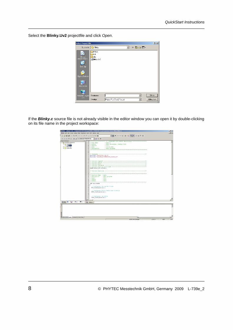
Select the Blinky.Uv2 projectfile and click Open.
If the Blinky.c source file is not already visible in the editor window you can open it by double-clicking on its file name in the project workspace:
8 © PHYTEC Messtechnik GmbH, Germany 2009 L-739e_2

Getting Started
3.3.1 Build the Project
• Build the target by either selecting the Build Target icon on the build toolbar or by selecting Project / Build target in the main menu bar.
• If any source file of the project contains any errors, they will be shown in the Output Window - Build tab. You can use the editor to correct the error(s) in the source code, to save the file and to repeat the build.
• If there are no errors, the code is ready to be downloaded into the internal RAM.
3.3.2 Start the Debugger and Download to nanoMODUL
• To start the µVision3 debug environment, click the debugger icon on the μVision3 toolbar or select Debug / Start/Stop Debug Session from the main menu bar.
• While using the µVision3 Evaluation Tools, the following warning will appear. Please select OK and continue.
• You will see a blue status bar from left to right at the bottom of your screen indicating the download process of the debug program.
If a problem occurs during data transfer, an error message will be displayed. If "No JTAG Devices Found" error should occur, make sure the target hardware is properly connected to a power supply and the host-PC using the Keil ULINK device (refer to section 3.2). If the data transfer was successful, a screen similar to the one shown below will appear. The Project Workspace window changes to the Register page. The debug toolbar is also displayed. In the lower part of the debug screen you will see the Command window.
© PHYTEC Messtechnik GmbH, Germany 2009 L-739e_2 9

QuickStart Instructions
You may need to open, resize and /or move some windows to make your screen look similar to the screen capture. You can open inactive windows by choosing the desired window from the View pull down menu. The debugger will run to the 'main' function and stop automatically. Notice the yellow arrow pointing to the first command in the 'main' function. Also notice the program counter R15 (PC) within the Project Window – Register page showing the start address of the 'main' function.
• Click on the Run icon and the program will run. Successful execution of the program will blink LED D1 on the nanoMODUL.
10 © PHYTEC Messtechnik GmbH, Germany 2009 L-739e_2

Debugging
4 Debugging
What you will learn with this example: • familiarizing yourself with simple debug functions provided by the Keil µVision3 debug
environment
• downloading example user code in the nanoMODUL
This Debugging section provides a basic introduction to the debug functions included in the Keil ARM/µVision3 evaluation tool chain. For a more detailed description of the debugging features, please refer to the appropriate manuals provided by Keil.
4.1 Keil µVision3 Debug Features
• The Debugger window toolbar gives access to the following debug commands: Reset, Run, Stop, Step Into, Step Over, Step Out and Run to Cursor line.
ResetRunStop
Step IntoStep OverStep Out
Run to Cursor line
• The first button on the debugger toolbar is the Reset button. The Reset command sets the program counter to 0.
• The button to the right of the Reset button starts the Run command. Clicking this button runs the program without active debug functions. To stop program execution at a desired point, a breakpoint can be placed before the Run button is pushed.
• The next button on the debugger toolbar is the Stop button. The Stop button interrupts and stops the running program at an undetermined location.
© PHYTEC Messtechnik GmbH, Germany 2009 L-739e_2 11

QuickStart Instructions
• The first button allowing exact control of the program execution is the Step Into button.
The Step Into command performs the execution of the command line to which the Current-Statement Arrow points. This can be a C command line or a single assembler line, depending on the current display mode. If the command line is a function call, Step Into jumps to the C function or subroutine, enabling you to explore the code contained in the accessed subroutine.
• The Step Over button is next on the debugger toolbar.
The Step Over command executes the command line, to which the Current-Statement Arrow points. This can be a C command line or a single assembler line, depending on the current display mode. If the command line is a function call, the function will be executed without single stepping into the function.
• The next button is the Step Out button.
Step Out is used to exit a function you are currently in. Step Out is very useful if you find yourself in a function you are not interested in and need to return quickly to your intended function.
• The last button on the debugger toolbar performs the Run to Cursor line command.
The Run to Cursor line command executes the program to the current cursor position within the code window. This allows use of the cursor line as a temporary breakpoint.
12 © PHYTEC Messtechnik GmbH, Germany 2009 L-739e_2
Debugging
4.2 Debugging Modes
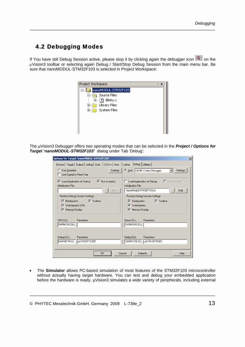
If You have still Debug Session active, please stop it by clicking again the debugger icon on the μVision3 toolbar or selecting again Debug / Start/Stop Debug Session from the main menu bar. Be sure that nanoMODUL-STM32F103 is selected in Project Workspace:
The µVision3 Debugger offers two operating modes that can be selected in the Project / Options for Target ‘nanoMODUL-STM32F103’ dialog under Tab ‘Debug’:
• The Simulator allows PC-based simulation of most features of the STM32F103 microcontroller without actually having target hardware. You can test and debug your embedded application before the hardware is ready. µVision3 simulates a wide variety of peripherals, including external
© PHYTEC Messtechnik GmbH, Germany 2009 L-739e_2 13

QuickStart Instructions
I/O and timers. The peripheral set is configured when you select a CPU from the device database for your target.
• USB-JTAG debugging interface adapters such as the Keil ULINK allow target-based debugging. With the ULINK interface you may connect directly to the target hardware using the JTAG interface. Debugging on the target hardware also enables the testing of peripheral components of the application and real-time program execution.
The Blinky demo in this section utilizes the ULINK Cortex Debugger environment.
• The ULINK Cortex Debugger settings can be viewed by selecting the Settings button:
14 © PHYTEC Messtechnik GmbH, Germany 2009 L-739e_2

Debugging
4.3 Starting the Debugger
• Open the Blinky project as described in section 3.3
• In the Select Target pull-down menu select the nanoMODUL-STM32F103 target.
• To start the ARM/µVision3 debug environment, click on the debugger icon on the μVision3
toolbar.
• Click on the Run icon and the program will run.
Successful execution of the program will blink LED D1 on the nanoMODUL.
© PHYTEC Messtechnik GmbH, Germany 2009 L-739e_2 15

QuickStart Instructions
5 Internal Flash Programming
What you will learn with this example: • downloading example user code to internal Flash memory using ARM/µVision3 tools
5.1 Loading the Blinky Application to internal Flash
This section shows how to download the Blinky executable into internal Flash of nanoMODUL • Open the Blinky project as described in section 3.3
• In the Select Target pull-down menu be sure that the nanoMODUL-STM32F103 target is selected.
• Download the code into Flash memory by either selecting the Download to Flash Memory icon
on the build toolbar or in the main menu bar select Flash / Download.
• The individual steps of the Flash download procedure can be viewed at the bottom of the μVision3 Output Window - Build tab.
• Wait until the programming is complete. This is indicated by the "Verify OK" message. The download utility will perform a reset and code will execute without further user interaction.
Successful execution of the program will blink LED D1 on nanoMODUL.
16 © PHYTEC Messtechnik GmbH, Germany 2009 L-739e_2

Getting More Involved
6 Getting More Involved
What you will learn within this example: • how to create a new project with the Blinky project as template
6.1 Creating a New Project
For ease of creating a new project for the nanoMODUL-STM32F103 it is recommended that the given Blinky project is used as a template. The Blinky project already has the target, linker, compiler, debugger, and startup code correctly configured for the nanoMODUL-STM32F103 target. Here are some suggestions for getting started:
• Create a new directory for your project and copy the contents of Blinky into the new directory.
• From the Project Workspace you can manage components of your project and add or remove source files, add code libraries, etc… For example, add source code from the Project Workspace window by right-clicking on the Source Code folder and selecting Add Files to Group ‘Source Code’.
• Advanced users can modify the target, compiler and linker settings from the Options for Target
area by selecting the Options for Target icon on the build toolbar or from the main toolbar menu select Project / Options for the Target 'nanoMODUL-STM32F103'.
© PHYTEC Messtechnik GmbH, Germany 2009 L-739e_2 17

QuickStart Instructions
18 © PHYTEC Messtechnik GmbH, Germany 2009 L-739e_2

Suggestions for Improvement
© PHYTEC Messtechnik GmbH, Germany 2009 L-739e_2 19
Document: nanoMODUL-STM32F103 QuickStart Instructions Keil Document number: L-739e_2, August 2009 How would you improve this manual?
Did you find any mistakes in this manual? page Submitted by: Customer number: Name: Company: Address: Return to: PHYTEC Technologie Holding AG Robert-Koch-Str. 39 55129 Mainz Fax: +49 (6131) 9221-26 [email protected]

Published by
© PHYTEC Messtechnik GmbH, Germany 2009 Document Number: L-739e_2 Printed in Germany