quick installation guide pcm-3730
TRANSCRIPT

PCM-3730 Installation Guide 1
Quick Installation Guide
Notice:
This guide is designed for experienced users tosetup the system within the shortest time. Fordetailed information, please always refer to theelectronic user's manual.
Safety Precautions
PCM-3730
PC/104 Plus Module
Part no. 2007373000 1st Ed. Printed in Taiwan April 2001
Quick Installation G
uide
Warning! Always completely disconnect the power cord fromyour chassis whenever you work with the hard-ware. Do not make connections while the power ison. Sensitive electronic components can bedamaged by sudden power surges. Only experi-enced electronics personnel should open the PCchassis.
Caution! Always ground yourself to remove any staticcharge before touching the CPU card. Modernelectronic devices are very sensitive to staticelectric charges. As a safety precaution, use agrounding wrist strap at all times. Place allelectronic components in a static-dissipativesurface or static-shielded bag when they are notin the chassis.
PCM-3730

PCM-3730
2 PCM-3730 Installation GuideBC-599/596
A Message to the Customer
AAEON Customer Services
Each and every AAEON product is built to the most exactingspecifications to ensure reliable performance in the harsh anddemanding conditions typical of industrial environments. Whetheryour new AAEON equipment is destined for the laboratory or thefactory floor, you can be assured that your product will provide thereliability and ease of operation for which the name AAEON hascome to be known.
Your satisfaction is our primary concern. Here is a guide toAAEON's customer services. To ensure you get the full benefit ofour services, please follow the instructions below carefully.
Technical Support
We want you to get the maximum performance from your products.So if you run into technical difficulties, we are here to help. For themost frequently asked questions, you can easily find answers inyour product documentation. These answers are normally a lotmore detailed than the ones we can give over the phone.
So please consult this manual first. If you still cannot find theanswer, gather all the information or questions that apply to yourproblem, and with the product close at hand, call your dealer. Ourdealers are well trained and ready to give you the support you needto get the most from your AAEON products. In fact, most problemsreported are minor and are able to be easily solved over the phone.
In addition, free technical support is available from AAEONengineers every business day. We are always ready to give adviceon application requirements or specific information on the installa-tion and operation of any of our products.

PCM-3730 Installation Guide 3
Quick Installation Guide
Product Warranty
AAEON warrants to you, the original purchaser, that each of itsproducts will be free from defects in materials and workmanship fortwo years from the date of shipment.
This warranty does not apply to any products which have beenrepaired or altered by persons other than repair personnel autho-rized by AAEON, or which have been subject to misuse, abuse,accident or improper installation. AAEON assumes no liabilityunder the terms of this warranty as a consequence of such events.
Because of AAEON's high quality-control standards and rigoroustesting, most of our customers never need to use our repair service.If an AAEON product is defective, it will be repaired or replaced atno charge during the warranty period. For out-of-warranty repairs,you will be billed according to the cost of replacement materials,service time, and freight. Please consult your dealer for moredetails.
If you think you have a defective product, follow these steps:
1. Collect all the information about the problem encountered. (Forexample, CPU type and speed, AAEON products used, otherhardware and software used, etc.) Note anything abnormal andlist any on-screen messages you get when the problem occurs.
2. Call your dealer and describe the problem. Please have yourmanual, product, and any helpful information readily available.
3. If your product is diagnosed as defective, obtain an RMA(return material authorization) number from your dealer. Thisallows us to process your return more quickly.
4. Carefully pack the defective product, a fully-completed Repairand Replacement Order Card and a photocopy proof of pur-chase date (such as your sales receipt) in a shippable container.A product returned without proof of the purchase date is noteligible for warranty service.
5. Write the RMA number visibly on the outside of the packageand ship it prepaid to your dealer.

PCM-3730
4 PCM-3730 Installation GuideBC-599/596
NoticeDear Customer,
Thank you for purchasing the PCM-3730 board. This QuickInstallation Guide is designed to help you to get the most out ofthe PCM-3730, please read it thoroughly before you install and usethe board. The product that you have purchased comes with antwo-year limited warranty, but AAEON will not be responsible formisuse of the product. Therefore, we strongly urge you to firstread the quick installation guide before using the product.To receive the latest version of the user manual, please visit ourWeb site at:
Http:\\WWW.AAEON.COM

PCM-3730 Installation Guide 5
Quick Installation Guide
Specification
• Supports 3 sets of 100Base-T Fast Ethernet
• 3 Intel 82559 GD
• Supports PC/104 and PC/104+
• Operating Temperature: 32 to 140 F (0 to 60 C)
• Board Size: 90mm(L) X 96mm(W)

PCM-3730
6 PCM-3730 Installation GuideBC-599/596
Installing PC/104 + modulesThe mainboard's PC/104 + connectors give you the flexibility toattach PC/104 + expansion modules. These modules perform thefunctions of traditional plug-in expansion cards, but save spaceand valuable slots.
Installing these modules on the mainboard is quick and simple. Thefollowing steps show how to mount the PC/104 + modules:
1. Remove the mainbaord from your system paying particularattention to the safety instructions already mentioned.
2. Make any jumper or link changes required to the mainboardnow. Once the PC/104 + module is mounted you may havedifficulty in accessing these.
3. Normal PC/104 + modules have male connectors and mountdirectly onto the main card. However, to ensure better busmatching, the connectors on the mainboard and the PC/104+module are both female. For this reason, you may need to usethe "male-male" adapter included with the mainboard in order toproperly connect your PC/104 + module. (Refer to the diagramon the following page.)
4. Mount the PC/104 + module onto the mainboard by pressingthe module firmly but carefully onto the mounting connectors.
5. Secure the PC/104 + module onto the mainboard using the fourmounting spacers and screws.

PCM-3730 Installation Guide 7
Quick Installation Guide
PC/104 & PC/104 Plus Module Mounting Diagram
������������������������������������������������������������������������������������������������
��������������������
��������������������
���������������������������������������������������������������������������
����������������������������������
������
��������������������
PC/104 Mounting Support
Female Male
PC/104 ModuleMain board
Female Male
PC/104 & PC/104 Plusmodule dimenstions (inches ±5%)
0.200
0 0 0.200 3.350
3.550
0.200
3.575
3.250 0.300
3.775 3.575
Installing PC 104 + Module
PCM-3730
8 PCM-3730 Installation GuideBC-599/596
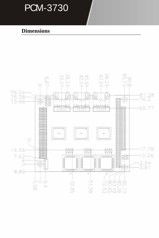
Dimensions

PCM-3730 Installation Guide 9
Quick Installation Guide
Locating Jumpers and Connectors
CN4
CN10
CN9
CN8
JP3
JP4
CN2
CN5
CN7
CN6
PCI 1
JP1
JP2
CN3
CN1

PCM-3730
1 0 PCM-3730 Installation GuideBC-599/596
Jumpers and Connectors
Name Function
JP1 LAN Enable/Disable
JP2 First LAN INT A, B, C, D
JP3 Second LAN INT A, B, C, D
JP4 Third LAN INT A, B, C, D
CN2 WOL Connector
CN4/5/6 100 Base-Tx Ethernet Connector
CN7 LAN LED
CN8/9/10 100 Base-Tx Ethernet Connector (Optional)
JP1 LAN Enabled/Disable1-2 Short: First LAN Disable
1-2 Open: First LAN Enable (Default)
3-4 Short: Second LAN Disable
3-4 Open: Second LAN Enable (Default)
5-6 Short: Third LAN Disable
5-6 Open: Third LAN Enable (Default)

PCM-3730 Installation Guide 11
Quick Installation Guide
JP2 First LAN INT A,B,C,D1-2 INTA (Default)
3-4 INTB
5-6 INTC
7-8 INTD
JP3 Second LAN INT A,B,C,D1-2 INTA
3-4 INTB (Default)
5-6 INTC
7-8 INTD
JP4 Third LAN INT A,B,C,D1-2 INTA
3-4 INTB
5-6 INTC (Default)
7-8 INTD

PCM-3730
1 2 PCM-3730 Installation GuideBC-599/596
CN2 WOL ConnectorPin Signal
Pin 1 5VSB
Pin 2 GND
Pin 3 WOL
Pin 4 SMBDATA
Pin 5 SMBCLK
CN4/5/6 100 Base-Tx Ethernet ConnectorPin Signal Pin Signal
Pin 1 TX+ Pin 9 NC
Pin 2 TX- Pin 10 NC
Pin 3 RX+ Pin 11 GND
Pin 4 NC Pin 12 GND
Pin 5 NC Pin 13 Active LED
Pin 6 RX- Pin 14 Link LED
Pin 7 NC Pin 15 +3.3V
Pin 8 NC Pin 16 Speed LED
PCM-3730 Installation Guide 13
Quick Installation Guide
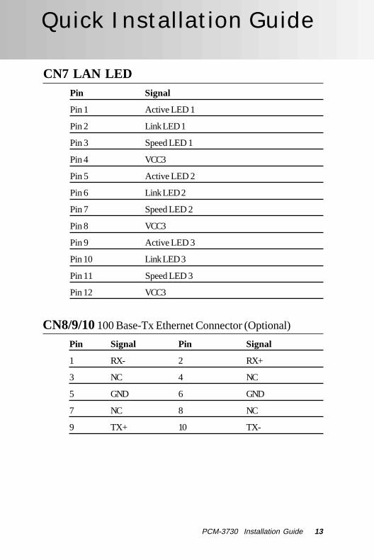
CN7 LAN LEDPin Signal
Pin 1 Active LED 1
Pin 2 Link LED 1
Pin 3 Speed LED 1
Pin 4 VCC3
Pin 5 Active LED 2
Pin 6 Link LED 2
Pin 7 Speed LED 2
Pin 8 VCC3
Pin 9 Active LED 3
Pin 10 Link LED 3
Pin 11 Speed LED 3
Pin 12 VCC3
CN8/9/10 100 Base-Tx Ethernet Connector (Optional)
Pin Signal Pin Signal
1 RX- 2 RX+
3 NC 4 NC
5 GND 6 GND
7 NC 8 NC
9 TX+ 10 TX-

PCM-3730
1 4 PCM-3730 Installation GuideBC-599/596
Adjusting Auto Boot Settings
Starting setupThe Auto Boot is immediately activated when you first turn on thecomputer. The Auto Boot reads system configuration informationin flash ROM and begins the process of checking out the systemand configuring it through the power-on self test (POST).
You can customize the behavior of the Boot Agent softwarethrough a pre-boot configuration program. You can access thispre-boot configuration setup program each time the client computercycles throught the boot process. The boot process is triggeredwhenever you perform any of the following boot events:
• Power on
• Hard Reset (if reset button is available)
• Soft Reset (Ctrl + Alt + Del)
• Operating system or application system restart
When the boot process begins, the screen clears and the computerbegins its Power On Self Test sequence. Shortly after completionof the POST, the Boot Agent software in the Flash ROM executes.The Boot Agent then displays an initialization message, similar tothe one below, indicating that the Boot is Active.
Initializing Intel (R) Boot Agent Version 4.X.XX
PXE m.m Build nnn (WfM w.w), RPL Vm.mm
Once you see this message, press Ctrl + S, this will allow you toenter the Auto Boot Menu.
If the message disappears before you respond and you still wish toenter Setup, restart the system to try again by turning it OFF thenON or pressing the RESET button on the system case. You mayalso restart by simultaneously pressing Ctr-Alt-Del.

PCM-3730 Installation Guide 15
Quick Installation Guide
Boot Agent Menu
ESC The <ESC> button will quit and shutdown the boot agent menu.
Space Bar The <Space Bar> will change the value ofthe configuration setting.
Enter After having selected the desired settinguse the <Enter> button to move on to thenext setting.
F4 To save and exit the Auto Boot setupmenu use the <F4> key.
Quit

PCM-3730
1 6 PCM-3730 Installation GuideBC-599/596
Boot Agent Menu Settings
Network Boot Protocol
Select PXE for use with Wfm-compatable network man-agement programs, such as Intel® Management Suite,Windows 2000 RIS, and Linux.
Select RPL for legacy-style remote booting.
If your boot agent does not support RPL, this setting will beunchangeable.
Boot Order
Allows you to select the order in which boot devices arequeried when the system boots. If your client computer'sBIOS supports the BIOS Boot Specification (BBS) orallows PnP-compliant selection of the boot order in theBIOS setup program, then this setting will always be "UseBIOS Setup Boot Order" and cannot be changed. In thiscase, refer to the BIOS setup manual specific to your clientcomputer to set up boot options.
If your client computer does not support BBS or PnPcompliant BIOS, you can select any one of the values listedin the Possible Values column of this table for this settingexcept for "Use BIOS Setup Boot Order".
PCM-3730 Installation Guide 17
Quick Installation Guide
Setup Menu Wait Time
The number of seconds the Boot Agent waits for you topress Ctrl + S during the system boot process.
The Choices: 0/2/3/5 seconds.
Legacy OS Wakeup Support
This setting applies only to Intel PRO/100 + WfM-compat-ible, 82559-based (or later) adapters.
Select Disable for this setting when using an ACPI Win-dows operating system such as Windows 2000 or Win-dows 98SE.
Select Enabled to allow non-Windows operating systems(such as DOS or NetWare) to make use of the Intel WfM-compatible adapter's remote makeup capability.
Consult your operating system instructions to determine ifyour operating system supports remote makeup, as well ashow to use this capability.
Show Setup Prompt
If you select Enable, the Ctrl + S prompt appears duringyour computer POST sequence.
If you select Disable, the Ctrl + S prompt does not appear.However, you can still press Ctrl + S to enter the setupprogram during your computer's POST sequence.

PCM-3730
1 8 PCM-3730 Installation GuideBC-599/596
Installing Intel 82559 for Windows 95 or 98 Ver. 1.0®
==>Place the Driver CDROM into your CDROM drive.==>Click on Start button==>Click on Settings button==>Click on Control Panel button==>Click on System button==>Click on Devise Manager button==>Click on PCI Ethernet Controller==>Click on Remove==>Click on OK==>Click on Refresh==>Click on Next==>Select the Optional: Other Location.....==>Click on Browse==>Select CDROM file==>Select Next==>Click on OK==>Click on Finish==>Then you will be asked to confirm the location of the select file....==>Now the shut down computer for restart Window should bevisible, follow the command and the chipset driver has beinstalled.
The LAN Driver must be installed threeseperate times, because PCM-3730 supportsthree different RJ-45 Connectors.

PCM-3730 Installation Guide 19
Quick Installation Guide
==>Place the Driver CDROM into your CDROM drive.==>Click on Start button==>Click on Settings button==>Click on Control Panel button==>Click on Network==>Click on yes==>Click on next==>Click on Select from list.......==>Click on have disk==>Type in file location: (CD Disk drive) E:\CDROM==>Click on OK==>Intel Pro Adapter will appear==>Click on OK==>Click on Next==>Click on Next==>Click on Next==>Click on Next==>Now the shut down computer for restart Window should bevisible, follow the command and the chipset driver has beinstalled.
Installing Intel 82559 for Windows NT®
The LAN Driver must be installed threeseperate times, because PCM-3730 supportsthree different RJ-45 Connectors.

PCM-3730
2 0 PCM-3730 Installation GuideBC-599/596
PCM-3730 Installation Guide 21
Quick Installation Guide