quadrangulation through morse-parameterization...
TRANSCRIPT
Quadrangulation through Morse-Parameterization Hybridization
XIANZHONG FANG, State Key Lab of CAD&CG, Zhejiang UniversityHUJUN BAO*, State Key Lab of CAD&CG, Zhejiang UniversityYIYING TONG,Michigan State UniversityMATHIEU DESBRUN, CaltechJIN HUANG*, State Key Lab of CAD&CG, Zhejiang University
Frame field
& Features
Parameterization
& Morse function
Final quad mesh
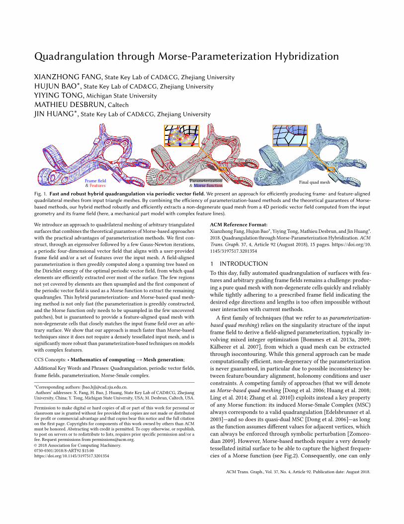
Fig. 1. Fast and robust hybrid quadrangulation via periodic vector field. We present an approach for efficiently producing frame- and feature-alignedquadrilateral meshes from input triangle meshes. By combining the efficiency of parameterization-based methods and the theoretical guarantees of Morse-based methods, our hybrid method robustly and efficiently extracts a non-degenerate quad mesh from a 4D periodic vector field computed from the inputgeometry and its frame field (here, a mechanical part model with complex feature lines).
We introduce an approach to quadrilateral meshing of arbitrary triangulated
surfaces that combines the theoretical guarantees ofMorse-based approaches
with the practical advantages of parameterization methods. We first con-
struct, through an eigensolver followed by a few Gauss-Newton iterations,
a periodic four-dimensional vector field that aligns with a user-provided
frame field and/or a set of features over the input mesh. A field-aligned
parameterization is then greedily computed along a spanning tree based on
the Dirichlet energy of the optimal periodic vector field, from which quad
elements are efficiently extracted over most of the surface. The few regions
not yet covered by elements are then upsampled and the first component of
the periodic vector field is used as a Morse function to extract the remaining
quadrangles. This hybrid parameterization- and Morse-based quad mesh-
ing method is not only fast (the parameterization is greedily constructed,
and the Morse function only needs to be upsampled in the few uncovered
patches), but is guaranteed to provide a feature-aligned quad mesh with
non-degenerate cells that closely matches the input frame field over an arbi-
trary surface. We show that our approach is much faster than Morse-based
techniques since it does not require a densely tessellated input mesh, and is
significantly more robust than parameterization-based techniques on models
with complex features.
CCS Concepts: • Mathematics of computing → Mesh generation;
Additional Key Words and Phrases: Quadrangulation, periodic vector fields,
frame fields, parameterization, Morse-Smale complex.
*Corresponding authors: {bao,hj}@cad.zju.edu.cn.
Authors’ addresses: X. Fang, H. Bao, J. Huang, State Key Lab of CAD&CG, Zhejiang
University, China; Y. Tong, Michigan State University, USA; M. Desbrun, Caltech, USA.
Permission to make digital or hard copies of all or part of this work for personal or
classroom use is granted without fee provided that copies are not made or distributed
for profit or commercial advantage and that copies bear this notice and the full citation
on the first page. Copyrights for components of this work owned by others than ACM
must be honored. Abstracting with credit is permitted. To copy otherwise, or republish,
to post on servers or to redistribute to lists, requires prior specific permission and/or a
fee. Request permissions from [email protected].
© 2018 Association for Computing Machinery.
0730-0301/2018/8-ART92 $15.00
https://doi.org/10.1145/3197517.3201354
ACM Reference Format:Xianzhong Fang, Hujun Bao*, Yiying Tong, Mathieu Desbrun, and Jin Huang*.
2018. Quadrangulation throughMorse-ParameterizationHybridization.ACMTrans. Graph. 37, 4, Article 92 (August 2018), 15 pages. https://doi.org/10.1145/3197517.3201354
1 INTRODUCTIONTo this day, fully automated quadrangulation of surfaces with fea-
tures and arbitrary guiding frame fields remains a challenge: produc-
ing a pure quad mesh with non-degenerate cells quickly and reliably
while tightly adhering to a prescribed frame field indicating the
desired edge directions and lengths is too often impossible without
user interaction with current methods.
A first family of techniques (that we refer to as parameterization-based quad meshing) relies on the singularity structure of the input
frame field to derive a field-aligned parameterization, typically in-
volving mixed integer optimization [Bommes et al. 2013a, 2009;
Kälberer et al. 2007], from which a quad mesh can be extracted
through isocontouring. While this general approach can be made
computationally efficient, non-degeneracy of the parameterization
is never guaranteed, in particular due to possible inconsistency be-
tween feature/boundary alignment, holonomy conditions and user
constraints. A competing family of approaches (that we will denote
as Morse-based quad meshing [Dong et al. 2006; Huang et al. 2008;
Ling et al. 2014; Zhang et al. 2010]) exploits instead a key property
of any Morse function: its induced Morse-Smale Complex (MSC)
always corresponds to a valid quadrangulation [Edelsbrunner et al.
2003]—and so does its quasi-dual MSC [Dong et al. 2006]—as long
as the function assumes different values for adjacent vertices, which
can always be enforced through symbolic perturbation [Zomoro-
dian 2009]. However, Morse-based methods require a very densely
tessellated initial surface to be able to capture the highest frequen-
cies of a Morse function (see Fig.2). Consequently, one can only
ACM Trans. Graph., Vol. 37, No. 4, Article 92. Publication date: August 2018.
92:2 • Fang, X. et al.
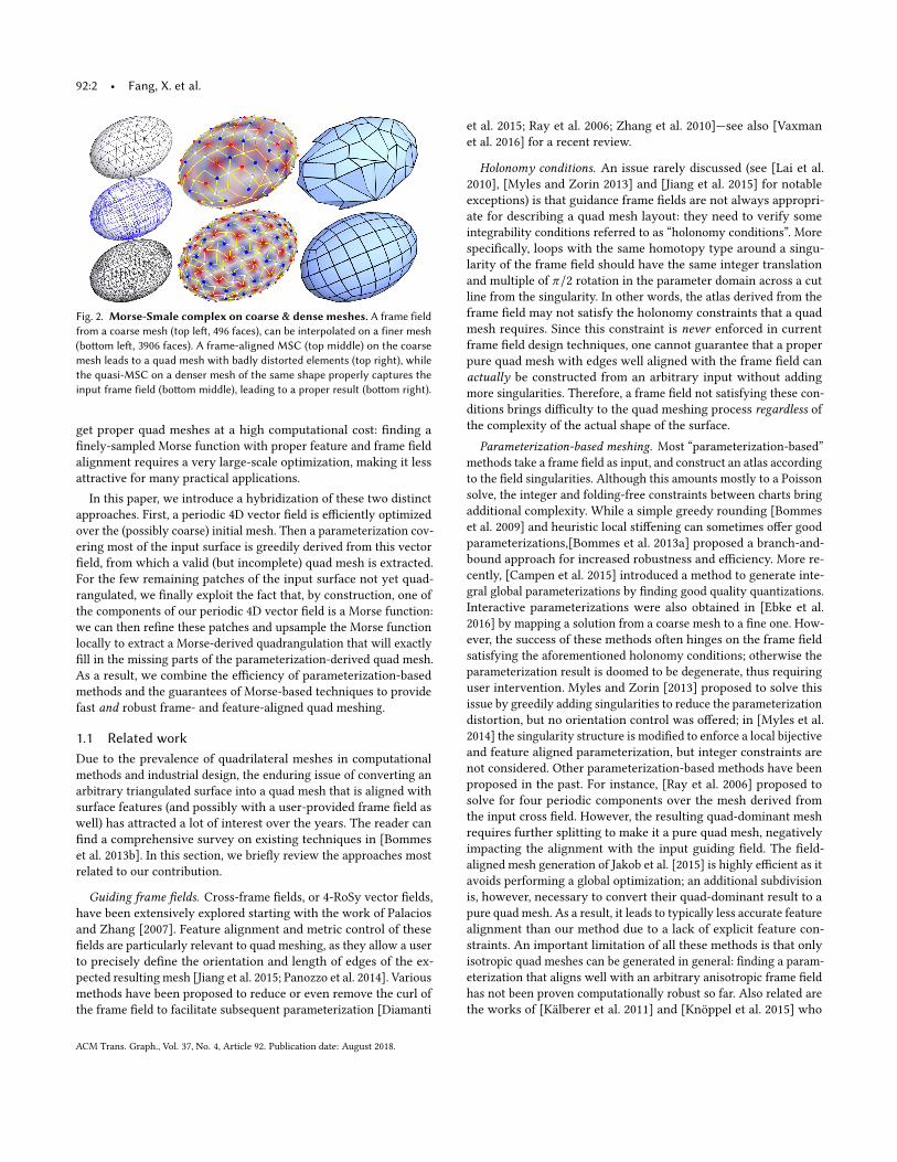
Fig. 2. Morse-Smale complex on coarse & dense meshes. A frame fieldfrom a coarse mesh (top left, 496 faces), can be interpolated on a finer mesh(bottom left, 3906 faces). A frame-aligned MSC (top middle) on the coarsemesh leads to a quad mesh with badly distorted elements (top right), whilethe quasi-MSC on a denser mesh of the same shape properly captures theinput frame field (bottom middle), leading to a proper result (bottom right).
get proper quad meshes at a high computational cost: finding a
finely-sampled Morse function with proper feature and frame field
alignment requires a very large-scale optimization, making it less
attractive for many practical applications.
In this paper, we introduce a hybridization of these two distinct
approaches. First, a periodic 4D vector field is efficiently optimized
over the (possibly coarse) initial mesh. Then a parameterization cov-
ering most of the input surface is greedily derived from this vector
field, from which a valid (but incomplete) quad mesh is extracted.
For the few remaining patches of the input surface not yet quad-
rangulated, we finally exploit the fact that, by construction, one of
the components of our periodic 4D vector field is a Morse function:
we can then refine these patches and upsample the Morse function
locally to extract a Morse-derived quadrangulation that will exactly
fill in the missing parts of the parameterization-derived quad mesh.
As a result, we combine the efficiency of parameterization-based
methods and the guarantees of Morse-based techniques to provide
fast and robust frame- and feature-aligned quad meshing.
1.1 Related workDue to the prevalence of quadrilateral meshes in computational
methods and industrial design, the enduring issue of converting an
arbitrary triangulated surface into a quad mesh that is aligned with
surface features (and possibly with a user-provided frame field as
well) has attracted a lot of interest over the years. The reader can
find a comprehensive survey on existing techniques in [Bommes
et al. 2013b]. In this section, we briefly review the approaches most
related to our contribution.
Guiding frame fields. Cross-frame fields, or 4-RoSy vector fields,
have been extensively explored starting with the work of Palacios
and Zhang [2007]. Feature alignment and metric control of these
fields are particularly relevant to quad meshing, as they allow a user
to precisely define the orientation and length of edges of the ex-
pected resulting mesh [Jiang et al. 2015; Panozzo et al. 2014]. Various
methods have been proposed to reduce or even remove the curl of
the frame field to facilitate subsequent parameterization [Diamanti
et al. 2015; Ray et al. 2006; Zhang et al. 2010]—see also [Vaxman
et al. 2016] for a recent review.
Holonomy conditions. An issue rarely discussed (see [Lai et al.
2010], [Myles and Zorin 2013] and [Jiang et al. 2015] for notable
exceptions) is that guidance frame fields are not always appropri-
ate for describing a quad mesh layout: they need to verify some
integrability conditions referred to as “holonomy conditions”. More
specifically, loops with the same homotopy type around a singu-
larity of the frame field should have the same integer translation
and multiple of π/2 rotation in the parameter domain across a cut
line from the singularity. In other words, the atlas derived from the
frame field may not satisfy the holonomy constraints that a quad
mesh requires. Since this constraint is never enforced in current
frame field design techniques, one cannot guarantee that a proper
pure quad mesh with edges well aligned with the frame field can
actually be constructed from an arbitrary input without adding
more singularities. Therefore, a frame field not satisfying these con-
ditions brings difficulty to the quad meshing process regardless ofthe complexity of the actual shape of the surface.
Parameterization-based meshing. Most “parameterization-based”
methods take a frame field as input, and construct an atlas according
to the field singularities. Although this amounts mostly to a Poisson
solve, the integer and folding-free constraints between charts bring
additional complexity. While a simple greedy rounding [Bommes
et al. 2009] and heuristic local stiffening can sometimes offer good
parameterizations,[Bommes et al. 2013a] proposed a branch-and-
bound approach for increased robustness and efficiency. More re-
cently, [Campen et al. 2015] introduced a method to generate inte-
gral global parameterizations by finding good quality quantizations.
Interactive parameterizations were also obtained in [Ebke et al.
2016] by mapping a solution from a coarse mesh to a fine one. How-
ever, the success of these methods often hinges on the frame field
satisfying the aforementioned holonomy conditions; otherwise the
parameterization result is doomed to be degenerate, thus requiring
user intervention. Myles and Zorin [2013] proposed to solve this
issue by greedily adding singularities to reduce the parameterization
distortion, but no orientation control was offered; in [Myles et al.
2014] the singularity structure is modified to enforce a local bijective
and feature aligned parameterization, but integer constraints are
not considered. Other parameterization-based methods have been
proposed in the past. For instance, [Ray et al. 2006] proposed to
solve for four periodic components over the mesh derived from
the input cross field. However, the resulting quad-dominant mesh
requires further splitting to make it a pure quad mesh, negatively
impacting the alignment with the input guiding field. The field-
aligned mesh generation of Jakob et al. [2015] is highly efficient as it
avoids performing a global optimization; an additional subdivision
is, however, necessary to convert their quad-dominant result to a
pure quad mesh. As a result, it leads to typically less accurate feature
alignment than our method due to a lack of explicit feature con-
straints. An important limitation of all these methods is that only
isotropic quad meshes can be generated in general: finding a param-
eterization that aligns well with an arbitrary anisotropic frame field
has not been proven computationally robust so far. Also related are
the works of [Kälberer et al. 2011] and [Knöppel et al. 2015] who
ACM Trans. Graph., Vol. 37, No. 4, Article 92. Publication date: August 2018.
Quadrangulation through Morse-Parameterization Hybridization • 92:3
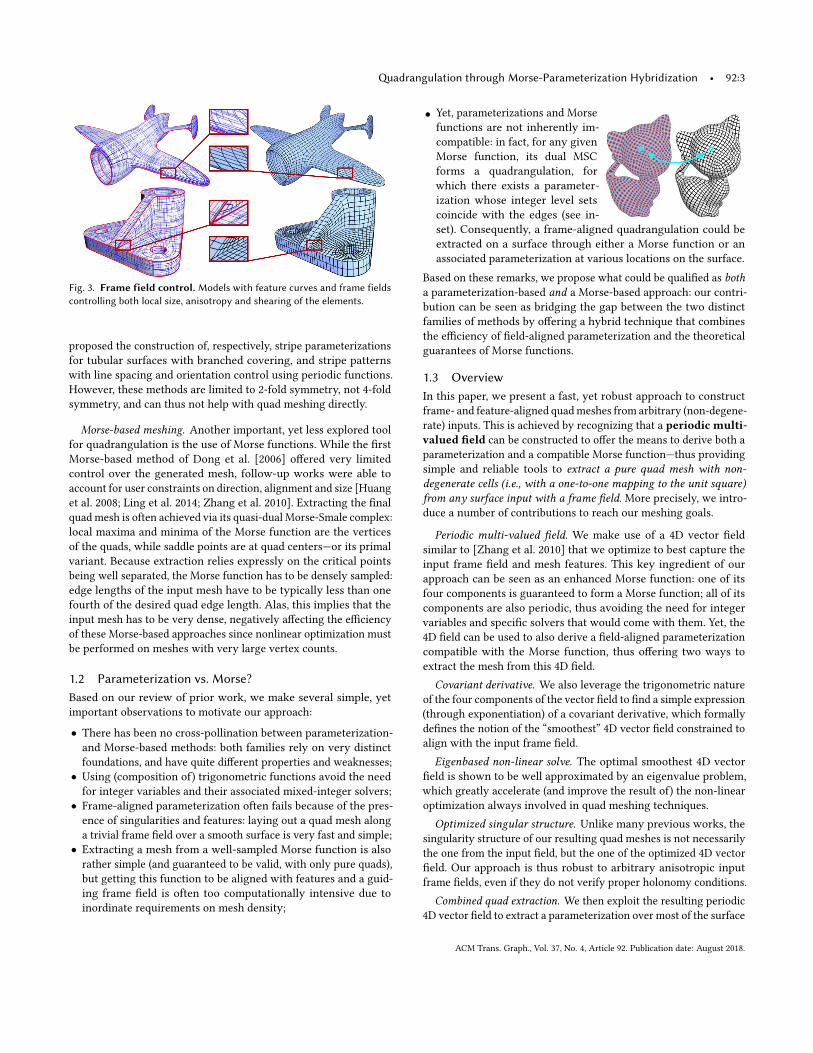
Fig. 3. Frame field control.Models with feature curves and frame fieldscontrolling both local size, anisotropy and shearing of the elements.
proposed the construction of, respectively, stripe parameterizations
for tubular surfaces with branched covering, and stripe patterns
with line spacing and orientation control using periodic functions.
However, these methods are limited to 2-fold symmetry, not 4-fold
symmetry, and can thus not help with quad meshing directly.
Morse-based meshing. Another important, yet less explored tool
for quadrangulation is the use of Morse functions. While the first
Morse-based method of Dong et al. [2006] offered very limited
control over the generated mesh, follow-up works were able to
account for user constraints on direction, alignment and size [Huang
et al. 2008; Ling et al. 2014; Zhang et al. 2010]. Extracting the final
quadmesh is often achieved via its quasi-dual Morse-Smale complex:
local maxima and minima of the Morse function are the vertices
of the quads, while saddle points are at quad centers—or its primal
variant. Because extraction relies expressly on the critical points
being well separated, the Morse function has to be densely sampled:
edge lengths of the input mesh have to be typically less than one
fourth of the desired quad edge length. Alas, this implies that the
input mesh has to be very dense, negatively affecting the efficiency
of these Morse-based approaches since nonlinear optimization must
be performed on meshes with very large vertex counts.
1.2 Parameterization vs. Morse?Based on our review of prior work, we make several simple, yet
important observations to motivate our approach:
• There has been no cross-pollination between parameterization-
and Morse-based methods: both families rely on very distinct
foundations, and have quite different properties and weaknesses;
• Using (composition of) trigonometric functions avoid the need
for integer variables and their associated mixed-integer solvers;
• Frame-aligned parameterization often fails because of the pres-
ence of singularities and features: laying out a quad mesh along
a trivial frame field over a smooth surface is very fast and simple;
• Extracting a mesh from a well-sampled Morse function is also
rather simple (and guaranteed to be valid, with only pure quads),
but getting this function to be aligned with features and a guid-
ing frame field is often too computationally intensive due to
inordinate requirements on mesh density;
• Yet, parameterizations and Morse
functions are not inherently im-
compatible: in fact, for any given
Morse function, its dual MSC
forms a quadrangulation, for
which there exists a parameter-
ization whose integer level sets
coincide with the edges (see in-
set). Consequently, a frame-aligned quadrangulation could be
extracted on a surface through either a Morse function or an
associated parameterization at various locations on the surface.
Based on these remarks, we propose what could be qualified as botha parameterization-based and a Morse-based approach: our contri-
bution can be seen as bridging the gap between the two distinct
families of methods by offering a hybrid technique that combines
the efficiency of field-aligned parameterization and the theoretical
guarantees of Morse functions.
1.3 OverviewIn this paper, we present a fast, yet robust approach to construct
frame- and feature-aligned quadmeshes from arbitrary (non-degene-
rate) inputs. This is achieved by recognizing that a periodic multi-valued field can be constructed to offer the means to derive both a
parameterization and a compatible Morse function—thus providing
simple and reliable tools to extract a pure quad mesh with non-degenerate cells (i.e., with a one-to-one mapping to the unit square)from any surface input with a frame field. More precisely, we intro-
duce a number of contributions to reach our meshing goals.
Periodic multi-valued field. We make use of a 4D vector field
similar to [Zhang et al. 2010] that we optimize to best capture the
input frame field and mesh features. This key ingredient of our
approach can be seen as an enhanced Morse function: one of its
four components is guaranteed to form a Morse function; all of its
components are also periodic, thus avoiding the need for integer
variables and specific solvers that would come with them. Yet, the
4D field can be used to also derive a field-aligned parameterization
compatible with the Morse function, thus offering two ways to
extract the mesh from this 4D field.
Covariant derivative. We also leverage the trigonometric nature
of the four components of the vector field to find a simple expression
(through exponentiation) of a covariant derivative, which formally
defines the notion of the “smoothest” 4D vector field constrained to
align with the input frame field.
Eigenbased non-linear solve. The optimal smoothest 4D vector
field is shown to be well approximated by an eigenvalue problem,
which greatly accelerate (and improve the result of) the non-linear
optimization always involved in quad meshing techniques.
Optimized singular structure. Unlike many previous works, the
singularity structure of our resulting quad meshes is not necessarily
the one from the input field, but the one of the optimized 4D vector
field. Our approach is thus robust to arbitrary anisotropic input
frame fields, even if they do not verify proper holonomy conditions.
Combined quad extraction. We then exploit the resulting periodic
4D vector field to extract a parameterization over most of the surface
ACM Trans. Graph., Vol. 37, No. 4, Article 92. Publication date: August 2018.
92:4 • Fang, X. et al.
Frame field MIQ Ours
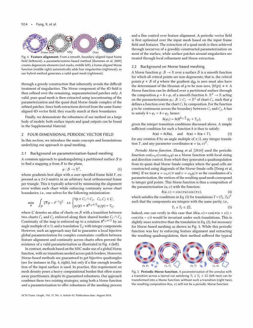
Fig. 4. Feature alignment. From a smooth, boundary-aligned input framefield (leftmost), a parameterization-based method [Bommes et al. 2009]creates degenerate elements (red marks, middle left); a frame-aligned Morsefunction (middle right) automatically adds four singularities (rightmost), soour hybrid method generates a valid quad mesh (rightmost).
through a greedy construction that inherently avoids the difficult
treatment of singularities. The Morse component of the 4D field is
then refined over the remaining, unparameterized patches only. Avalid, pure quad mesh is then extracted using isocontouring of the
parameterization and the quasi-dual Morse-Smale complex of the
refined patches. Since both extractions derived from the same frame-
aligned 4D vector field, they exactly match at their boundaries.
Finally, we demonstrate the robustness of our method on a large
body of models: both surface inputs and quad outputs can be found
in the Supplemental Material.
2 FOUR-DIMENSIONAL PERIODIC VECTOR FIELDIn this section, we introduce the main concepts and formulations
underlying our approach to quad meshing.
2.1 Background on parameterization-based meshingA common approach to quadrangulating a partitioned surface S is
to find a mapping φ from S to the plane,
φ : S → R2, (1)
whose gradients best align with a user-specified frame field F , ex-pressed as a 2×2-matrix in an arbitrary local orthonormal frame
per triangle. This is typically achieved by minimizing the alignment
error within each chart while enforcing continuity across chart
boundaries; i.e., one solves for the following minimization:
min
φ
∫S
∥∇φ − F−1∥2 s.t.
{∀p ∈ Ci ∩Cj , Ci ,Cj ∈ C,
φi (p) = Rki jπ /2φ j (p) +Ti j .
where C denotes an atlas of charts on S with a transition between
two charts Ci and Cj enforced along their shared border Ci ∩ Cj .
Continuity of the map is enforced up to a rotation Rki jπ /2 by an
angle multiple of π/2, and a translationTi j with integer components.
However, such an approach may fail to guarantee a local bijective
global parameterization for complex constraints: conflicts between
feature alignment and continuity across charts often prevent the
existence of a valid parameterization as illustrated in Fig. 4 (left).
In contrast, methods based on theMSCmake use of a globalMorse
function, with no transitions needed across patch borders. Moreover,
Morse-based methods are guaranteed to get bijective quadrangles
(see for instance in Fig. 4, right), but only if a fine enough tessella-
tion of the input surface is used. In practice, this requirement on
mesh density poses a heavy computational burden that often scares
away practitioners, despite its guaranteed robustness. Our approach
combines these two existing strategies, using both a Morse function
and a parameterization to offer robustness of the meshing process
and a fine control over feature alignment. A periodic vector field
is first optimized over the input mesh based on the input frame
field and features. The extraction of a quad mesh is then achieved
through isocurves of a greedily-constructed parameterization on
most of the surface, while surface patches around singularities are
treated through local refinement and Morse extraction.
2.2 Background on Morse-based meshingA Morse function д : S → R over a surface S is a smooth function
for which all critical points are non-degenerate; that is, the critical
points p ∈ S of д where the gradient dдp is zero must also have
the determinant of the Hessian of д to be non-zero, |H (p)| , 0. A
Morse function can be defined over a partitioned surface through
the composition д = h ◦ φi of a smooth function h : R2 → R acting
on the parameterization φi : S ⊃ Ci → R2of chart Ci , such that д
defines a function over the chartCi by composition. For the function
д to be continuous across the boundary between Ci and Cj , h has
to satisfy h ◦ φi = h ◦ φ j , hence:
h(φi ) = h(Rki j π
2 φ j +Ti j ), (2)
given the integer transition conditions discussed above. A simple
sufficient condition for such a function h is thus to satisfy:
h(u) = h(Ru), and h(u) = h(u +T ), (3)
for any rotation R by an angle multiple of π/2, any integer transla-
tion T , and any parameter coordinates u = (u,v)T .
Periodic Morse function. Zhang et al. [2010] used the periodic
function cos(ωxx) cos(ωyy) as a Morse function with local sizing
and direction control, from which they generated a quadrangulation
from its quasi-dual Morse-Smale complex where the quad cells are
constructed using diagonals of the Morse-Smale cells [Dong et al.
2006]. If we treat u = ωxx/π and v = ωyy/π as the coordinates of a
parameterization, the vertices of the resulting quadmesh correspond
to integer grid points. This Morse function is thus a composition of
the parameterization (u,v) with the function:
h(u,v) = cos (πu) cos (πv), (4)
which satisfies the conditions in Eq. (3) for translationsT = (T1,T2)T
such that the components are integers with the same parity, i.e.,
T1 ±T2 ∈ 2Z. (5)
Indeed, one can verify in this case that 2h(u,v)= cos(π (u + v)) +cos(π (u − v)) would be invariant under such translations. This is
slightly more restrictive than the translation in Eq. (2), but necessary
for Morse-based meshing as shown in Fig. 5. While this periodic
function was key to enforcing feature alignment and extracting
the resulting quadrangulation, their method suffered the typical
(0, 8) (1, 7) (0, 7) (1, 8)
Fig. 5. Periodic Morse function. A parameterization of the annulus witha transition across a lateral cut satisfying T1 ± T2 ∈ 2Z (left two) can betransformed into a Morse function; without such a transition (right two),the resulting composition h(u, v) will not be a periodic Morse function.
ACM Trans. Graph., Vol. 37, No. 4, Article 92. Publication date: August 2018.
Quadrangulation through Morse-Parameterization Hybridization • 92:5
drawbacks of Morse-based approaches. Instead, our work will use a
four-dimensional periodic vector field, already introduced in [Zhang
et al. 2010] but where only the first component was used for mesh
extraction. We show that a global parameterization can be reliably
recovered if the four components are exploited, and that this ap-
proach is robust even on coarse input triangle meshes, in marked
contrast with existing Morse-based quad meshing techniques.
2.3 Periodic four-dimensional vector fieldIn our approach, we use a four-component periodic functionψ :
ψ (u,v) = (cc(u,v), sc(u,v), cs(u,v), ss(u,v))T , (6)
whose components are four periodic scalar functions defined ascc(u,v) = cos (πu) cos (πv)
sc(u,v) = sin (πu) cos (πv)
cs(u,v) = cos (πu) sin (πv)
ss(u,v) = sin (πu) sin (πv)
(7)
Further, we denote by Ψ the four-dimensional vector field over
the surface S defined by composing the periodic functionψ with a
parameterization φ(p) = (u(p),v(p))T :
Ψ(p) = ψ ◦ φ(p), ∀p ∈ S. (8)
Note that the first component (Ψ0 = cc(u,v)) of this vector fieldis precisely the periodic Morse function h discussed in Sec. 2.2.
However, the other coordinates do not form Morse functions as
they are not invariant under π/2 rotation of the parameterization:
denoting the counterclockwise rotation of R2by π/2 as J , one has
ψ (Ju) = Jψ (u)
instead, where J is a matrix performing a permutation of the com-
ponents up to a sign as easily verified via trigonometric identities:
J =©«
1 0 0 0
0 0 −1 0
0 1 0 0
0 0 0 −1
ª®®®¬ .This implies that the vector field Ψ satisfies the following property
at the boundary between two charts Ci and Cj :
Ψ(p) = ψ (φi (p)) = ψ (Jki jφ j (p) +Ti j ) = J
ki jψ (φ j (p)),
where the translations Ti j between charts are naturally canceled
by our choice of the four periodic components of ψ , and where
we denoted the transition rotation between charts i and j by an
angle of ki jπ/2 as Jki j . Finally, we note that our choice of the four-component periodic function trivially implies the following proper-
ties for the vector field Ψ due to the use of trigonometric functions:
∥Ψ∥2 = 1 and Ψ0Ψ3 = Ψ1Ψ2.
Our approach will look for a smooth 4D vector field Ψ satisfying
these simple relationships between all four components, so as to
define a quad mesh with non-degenerate cells (i.e., cells with a
one-to-one map to the square).
2.4 Differential property of 4D vector fieldThe differential of the periodic functionψ (u,v) is easily found, usingthe derivatives of sin and cos, to be
dψ = π W (du,dv) ψ , (9)
whereW is the matrix-valued function
W (du,dv) =
0 −du −dv 0
du 0 0 −dvdv 0 0 −du0 dv du 0
. (10)
This property implies that a vector field Ψ based onψ and a param-
eterization φ(p) = (u(p),v(p)) has to satisfy (by chain rule):
∂Ψ
∂p− π W (
∂u
∂p,∂v
∂p) Ψ = 0.
Since we wish to construct a vector field Ψ before deducing a param-
eterization φ from it, we instead exploit the input guidance frame
field F , with which we want dφ to be aligned: we form a connection
(or covariant derivative [Crane et al. 2010])ˆ∇Ψ defined on the 4D
vector bundle S ×R4, which, for any tangent vector v, is defined as:
ˆ∇vΨ =∂Ψ
∂pv − πW (F−1v)Ψ. (11)
Note that we have effectively removed the explicit use of the pa-
rameterization: this differential expression should hold if the vector
field Ψ were to derive from an F -aligned parameterization.
2.5 Feature and boundary alignmentFeature and boundary alignment are easily incorporated as con-
straints on Ψ as proposed in [Zhang et al. 2010]. Indeed,
• for any point p along a feature or a boundary, one must have
u(p) ∈Z or v(p) ∈Z. This is achieved by enforcing:
Ψ3(p) = ss(u(p),v(p)) = 0; (12)
• for any corner point p, i.e., a sharp corner along a feature or
boundary, we need u(p) ∈Z and v(p) ∈Z. Thus we simply force
the components sc, cs, ss of Ψ to be zero:
Ψ1(p) = Ψ2(p) = Ψ3(p) = 0. (13)
2.6 Optimal periodic vector fieldIn order to obtain the simplest layout that satisfies all feature and
boundary alignments, we search for the smoothest Ψ for a given
guidance frame field F by simply minimizing the Dirichlet energy
E(Ψ)=
∫S
∥ ˆ∇Ψ∥2 s.t.
{∥Ψ∥2 = 1, Ψ0Ψ3 = Ψ1Ψ2,
and all feature constraints.(14)
We will show that this optimization of a 4D vector field is actually
simple to perform reliably by exploiting the fact that, once the first
two constraints are omitted, it corresponds to a simple quadratic
functional minimization.
3 PERIODIC VECTOR FIELD GENERATIONWe now explain how the geometric approach we described above is
easily implemented and solved numerically.
3.1 Discrete setupGiven a piecewise-linear approximationM of a surface S, with
vertices V and triangles T , we store the user-prescribed input
frame field as one frame Ft per triangle t ∈T [de Goes et al. 2015].
We discretize our periodic 4D vector field at vertices as a four-
component vector Ψp on each vertex p ∈V , and the vector stacking
all the values Ψp is denoted asΨΨΨ. Since the expression of Ψp depends
ACM Trans. Graph., Vol. 37, No. 4, Article 92. Publication date: August 2018.
92:6 • Fang, X. et al.
on the local frame, we have to define one frame per vertex as well.
Without loss of generality, we pick the vertex frame Fp to be the
frame Ft0, where t0 is one triangle in the one-ring of p.
3.2 Discretization of smoothness energyHalf-edge based discretization. Based on our discrete setup, we
discretize the integral of ∥ ˆ∇Ψ∥2 by summing up one term per half
edge, or equivalently, two terms per edge (p,q) ∈ E as we now
detail. For a half edge epq from vertex p to vertex q in triangle t ,the parallel-transport of Ψp along epq in the connection
ˆ∇ defined
by Ft is exp
(πW (F−1
t epq ))Ψp [Liu et al. 2016] since the continuous
field Ψ obeys the differential property given in Eq. (11). The edge
contribution to the discrete version of the smoothness energy E(Ψ)=∫S∥ ˆ∇Ψ∥2 is thus:
Epq =|t |
2|epq |2∥Ψq,t − exp
(πW (F−1
t epq ))Ψp,t ∥
2, (15)
where |t | is the area of triangle t , and Ψp,t is the expression of Ψp in
the frame of t , the latter being evaluated as Ψp,t = Jkpt Ψp where kpt
encodes the integer multiple of π/2 rotation between point p and
triangle t . (We will provide in the next paragraph a frame alignment
value for kpt based on the input frame field). Note that the matrix
exponential can be evaluated in closed form, since:
exp(πW )=
cc(du, dv) −sc(du, dv) −cs(du, dv) ss(du, dv)sc(du, dv) cc(du, dv) −ss(du, dv) −cs(du, dv)cs(du, dv) −ss(du, dv) cc(du, dv) −sc(du, dv)ss(du, dv) cs(du, dv) sc(du, dv) cc(du, dv)
.Frame alignment calculation. The input frame field F , given as a
frame for each face of the input triangle mesh, can be a cross field or
an arbitrary, non-orthogonal frame field [Jiang et al. 2015; Panozzo
et al. 2014]. We compute the alignment angles in Eq. (15) based on
the frames of the two faces across a common edge: for two adjacent
triangles s, t ∈ T , the best alignment angle kstπ/2 between frame
Fs and frame Ft is computed through
kst = argmin
k∥Fs J
4−k − Ft ∥2,k ∈ {0, 1, 2, 3},
where Fs and Ft are first aligned through the Levi-Civita connectionacross the common edge [de Goes et al. 2015].
For the local frame needed to express Ψ at each vertex p, wesimply use the frame of one of the adjacent faces t0. The best localalignment from p to that face then becomes kpt0
=0. Assuming the
faces incident to p are (t0, t1, ..., tm ) in counterclockwise order, the
best alignment for the other faces are simply given as
kptj =
( j−1∑i=0
kti ti+1
)mod 4.
Constrained optimization. Summing up all the half edge contri-
butions, we can now formulate the optimization of the discretized
smoothness energy E(ΨΨΨ) =∑
edge (p,q) Epq (quadratic in ΨΨΨ) as
min
ΨΨΨE(ΨΨΨ) s.t.
∥Ψp ∥
2 = 1 and Ψ0
pΨ3
p = Ψ1
pΨ2
p , p ∈ V
Ψ3
p = 0, p ∈ Vb
Ψ1
p = Ψ2
p = 0, p ∈ Vc
(16)
whereVb is the set of vertices on boundaries and feature curves, and
Vc is the set of corner vertices, i.e., vertices that belong to multiple
feature/boundary edges.
ss ,0 ss =0
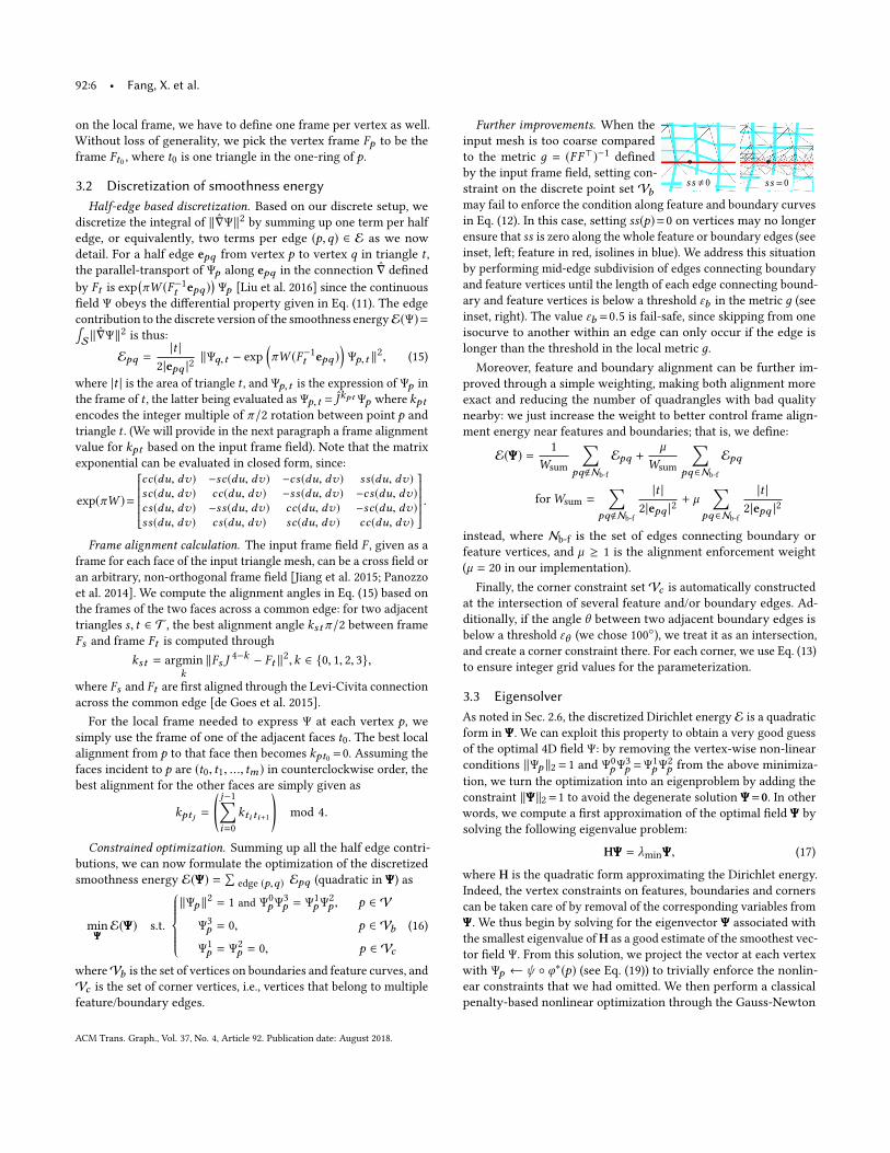
Further improvements. When the
input mesh is too coarse compared
to the metric д = (FF⊤)−1defined
by the input frame field, setting con-
straint on the discrete point set Vbmay fail to enforce the condition along feature and boundary curves
in Eq. (12). In this case, setting ss(p)=0 on vertices may no longer
ensure that ss is zero along the whole feature or boundary edges (seeinset, left; feature in red, isolines in blue). We address this situation
by performing mid-edge subdivision of edges connecting boundary
and feature vertices until the length of each edge connecting bound-
ary and feature vertices is below a threshold εb in the metric д (see
inset, right). The value εb =0.5 is fail-safe, since skipping from one
isocurve to another within an edge can only occur if the edge is
longer than the threshold in the local metric д.
Moreover, feature and boundary alignment can be further im-
proved through a simple weighting, making both alignment more
exact and reducing the number of quadrangles with bad quality
nearby: we just increase the weight to better control frame align-
ment energy near features and boundaries; that is, we define:
E(ΨΨΨ) =1
Wsum
∑pq<Nb-f
Epq +µ
Wsum
∑pq∈Nb-f
Epq
forWsum =∑
pq<Nb-f
|t |
2|epq |2+ µ
∑pq∈Nb-f
|t |
2|epq |2
instead, where Nb-f
is the set of edges connecting boundary or
feature vertices, and µ ≥ 1 is the alignment enforcement weight
(µ = 20 in our implementation).
Finally, the corner constraint setVc is automatically constructed
at the intersection of several feature and/or boundary edges. Ad-
ditionally, if the angle θ between two adjacent boundary edges is
below a threshold εθ (we chose 100◦), we treat it as an intersection,
and create a corner constraint there. For each corner, we use Eq. (13)
to ensure integer grid values for the parameterization.
3.3 EigensolverAs noted in Sec. 2.6, the discretized Dirichlet energy E is a quadratic
form in ΨΨΨ. We can exploit this property to obtain a very good guess
of the optimal 4D field Ψ: by removing the vertex-wise non-linear
conditions ∥Ψp ∥2 =1 and Ψ0
pΨ3
p =Ψ1
pΨ2
p from the above minimiza-
tion, we turn the optimization into an eigenproblem by adding the
constraint ∥ΨΨΨ∥2=1 to avoid the degenerate solution ΨΨΨ=0. In other
words, we compute a first approximation of the optimal field ΨΨΨ by
solving the following eigenvalue problem:
HΨΨΨ = λminΨΨΨ, (17)
where H is the quadratic form approximating the Dirichlet energy.
Indeed, the vertex constraints on features, boundaries and corners
can be taken care of by removal of the corresponding variables from
ΨΨΨ. We thus begin by solving for the eigenvector ΨΨΨ associated with
the smallest eigenvalue ofH as a good estimate of the smoothest vec-
tor field Ψ. From this solution, we project the vector at each vertex
with Ψp ← ψ ◦ φ∗(p) (see Eq. (19)) to trivially enforce the nonlin-
ear constraints that we had omitted. We then perform a classical
penalty-based nonlinear optimization through the Gauss-Newton
ACM Trans. Graph., Vol. 37, No. 4, Article 92. Publication date: August 2018.
Quadrangulation through Morse-Parameterization Hybridization • 92:7
method to solve for the original constrained minimization:
min
ΨΨΨE(ΨΨΨ) +
wr|V|
∑p∈V
( (∥Ψp ∥2
2−1)2 + ∥Ψ0
pΨ3
p−Ψ1
pΨ2
p ∥2
2)
s.t. Ψ3
p = 0, p ∈ Vb ; Ψ1
p = Ψ2
p = 0, p ∈ Vc .
(18)
where the weightwr allows for the enforcement of the nonlinear
constraints (wr =1 in our implementation, and we assume conver-
gence when gradient magnitude is below 1e-3). We eliminate the
constrained variables from the target function, replacing them by
their values directly.
We will show in Sec. 5 that this two-step procedure is very effi-
cient as the eigenvalue problem provides a close estimate of the final
solution, making the non-linear solve much more robust against
local minima (see Figs. 15 and 16). This is a particularly key feature
of our seemingly-redundant 4D vector field: it allows us to turn the
highly non-linear problem of frame alignment into a constrained
minimization well approximated by an eigenvalue problem.
4 FROM PERIODIC FIELD TO QUADRANGULATIONFrom the periodic vector field resulting from our constrained energy
minimization, a global parameterization needs to be extracted. We
offer a fast two-stage approach which greedily constructs a parame-
terization in regions of low Dirichlet energy first, then exploits the
Morse function Ψ0in regions where the greedy construction failed
to provide a satisfactory parameterization to quadrangulate. More
specifically, after the greedy parameterization stage, we extract
quadrangles centered at points with half-integer parameter values.
The union of these quadrangles is denoted QR , the complement of
which is defined as the singular regionMS . In the Morse-based
stage, we refine Ψ inMS by solving the constrained optimization on
a locally refined mesh to obtain a high-quality MSC, with the origi-
nal Ψ fixed on the common boundary QR∩MS to ensure flawless
compatibility between the two regions, see Fig. 6. This technique
allows us to extract a pure quad mesh efficiently as we now detail.
4.1 OverviewOnce a periodic field Ψ is known, finding a corresponding parame-
terization φ is no easy task: there is an infinite number of solutions
differing by integer offsets. Indeed, suppose we know a parameteri-
zation φ∗ which matches Ψ, then parameterizations of the form
φ(p) = φ∗(p) + (a,b)T , a ± b ∈ 2Z
are also valid due to the periodicity ofψ .
From all possible parameterizations, we need to construct one
that is best aligned with the input frame field; that is, one for which∫M∥∇φ − F−1∥2 is small. However, optimizing frame alignment
through integer programming while forcing the parameterization
to be seamless is computationally intractable in practice. Directly
exploiting the fact that the first component of Ψ is a Morse function
will also fail for coarse input meshes. We thus propose to proceed
instead in two steps:
• First, a local parameterization φ∗(p)= (u∗(p),v∗(p))T is assigned
to each vertex p based on the value of Ψp . From these local param-
eter values, we greedily construct a valid “spanning parameteriza-
tion” φ that covers most of the input surface through an efficient
Dirichlet energy guided mesh traversal. Here we leverage the fact
that a low local Dirichlet energy of the optimal periodic vector
field implies smoothness, hence easy construction of a parame-
terization. From this spanning parameterization, we can extract
most of the quad mesh;
• We then exploit the Morse function Ψ0to extract the missing
quadrangles using the quasi-dual Morse-Smale complex found
after refinement of the input mesh in the remaining regions.
We now review these two steps and discuss why they guarantee the
fast extraction of a seamless, pure quad mesh.
(a) (b)
(c) (d) (e)
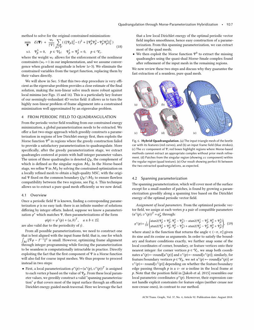
Fig. 6. HybridQuadrangulation. (a) The input triangle mesh of the beetlecar with its features (red curves), and (b) an input frame field (blue strokes).(c) The cc component of Ψ; red boxes highlight regions where Morse-basedmethods cannot extract an appropriate complex without prior mesh refine-ment. (d) Patches from the singular region (showing cc component) withinthe regular region (quad texture). (e) Our result showing perfect fit betweenthe two extracted quadrangulations, as expected.
4.2 Spanning parameterizationThe spanning parameterization, which will cover most of the surface
except for a small number of patches, is found by growing a param-
eterization greedily along a spanning tree based on the Dirichlet
energy of the optimal periodic vector field.
Assignment of local parameters. From the optimized periodic vec-
tor field, we assign at each vertex p a pair of compatible parameters
(u∗(p),v∗(p))T =φ∗p through:
φ∗(p)= 1
2π
(atan2(Ψ1
p + Ψ2
p ,Ψ0
p − Ψ3
p ) − atan2(Ψ1
p − Ψ2
p ,Ψ0
p + Ψ3
p )
atan2(Ψ1
p + Ψ2
p ,Ψ0
p − Ψ3
p ) + atan2(Ψ1
p − Ψ2
p ,Ψ0
p + Ψ3
p )
), (19)
where atan2 is the function that returns the angle ∈ (−π ,π ] givenits sine and its cosine as arguments. In order to satisfy the bound-
ary and feature conditions exactly, we further snap some of the
local coordinates of corner, boundary, or feature vertices onto their
nearest integer: for corner vertices p ∈ Vc , we snap both coordi-
nates u∗(p)←round[u∗(p)] and v∗(p)←round[v∗(p)]; similarly, for
feature/boundary vertices p ∈Vb , we set u∗(p)← round[u∗(p)] or
v∗(p)←round[v∗(p)] depending on whether the feature/boundary
edge passing through p is a v- or u-isoline in the local frame at
p. Note that the position field in [Jakob et al. 2015] resembles our
local parametric coordinates φ∗(p). However, their expression can-
not handle explicit constraints for feature edges (neither crease nor
non-crease ones), in contrast to our method.
ACM Trans. Graph., Vol. 37, No. 4, Article 92. Publication date: August 2018.
92:8 • Fang, X. et al.
Construction of spanning tree. Given local parametric coordinates
φ∗(p), we wish to find a “spanning” parameterization φ by advanc-
ing along a spanning tree of the dual graph of the mesh. To find a
good spanning tree through which the parameterization can easily
be computed, we drive the construction of the spanning tree based
on the value of the smoothness energy E(ΨΨΨ). More precisely, we
define the Dirichlet energy for each triangle t as the sum of the
energy values of its edges defined in Eq. (15),
Et =∑
(p,q)⊂t ∈T
(Epq + Eqp ). (20)
The root of the spanning tree is then set on the face tmin with the
minimum triangle energy value. The triangle tmin and its adjacent
neighbors are then pushed onto a heap of unvisited triangles, with
the triangle energy value as the key. We then repeat the following
operations until the heap is empty: remove the triangle with the
minimum key from the heap, add the dual edge to the adjacent
visited node to the tree, and push its adjacent triangles onto the
heap. This procedure forms a spanning tree that cuts the input mesh
into a topological diskMc .
Greedy construction of parameterization. We are now ready to
construct the spanning parameterization. We treat each triangle as
its own chart, such that a vertex p is assigned a different parameter
value per adjacent triangle. We will denote φt (p) the coordinates ofp within the chart formed by triangle t .
With the spanning tree and its implied topological disk, we can
now remove the constraints of transition between triangle charts
by simply setting the transition for all tree edges to zero rotation
and zero translation. We then traverse the spanning tree we just
constructed, and layout triangle-by-triangle the spanning parame-
terization that minimizes frame alignment distortion with respect
to the frame field F . We begin by setting φtmin(p)=φ∗(p) for one of
the vertices of tmin. The counterclockwise neighbor q of p in tmin
is then given the parametric coordinates φtmin(q) =φ∗(q)+(a,b)T
with a ± b ∈2Z such that the integrated gradient φtmin(q)−φtmin
(p)best matches the desired parametric integrated gradient dφ along
the edge epq in F . As we traverse the tree (i.e., as we cross edge(p,q) to go from triangle s = (m,p,q) to t = (p, r ,q)), we begin by
copying the parameter values of the two vertices of the edge such
that φt (p) = φs (p) and φt (q) = φs (q)—hence imposing a chart tran-
sition with no rotation and no translation. We then need to find
the parameter coordinates φt (r ) for the unvisited vertex r whichminimizes frame alignment distortion and find it by solving:
min
φt (r )∥φt (r ) − φt (p) − dφpr ∥
2 + ∥φt (r ) − φt (q) − dφqr ∥2
s.t.
{φt (r )= R(kr t+kt )
π2φ∗(r )+(T 0
t,r ,T1
t,r )T , T 0
t,r ±T1
t,r ∈2Z,
det(∇φt )>0.
Here, kt denotes the rotation determined by the spanning tree
through kt = kts +ks for s being the parent node of t , and we
set the root rotation ktminto 0. This minimization is trivially solved
by first computing the optimal parameter values φr without the
integer constraints, then testing the nine nearby integer grid points
to find the best valid match. Once φt (r ) is found, we move on to
the next tree edge. By the end of the tree traversal, we have a span-
ning parameterization with low frame alignment distortion almost
everywhere, see Fig. 8.
Robustness against floating point operations. In order to avoid float-ing point issues during the extraction of quadrangles from the pa-
rameterization, we add one last rounding of the value of φt (p) in our
implementation: we compute the value z=maxt,v ∈M,i ∈{0,1} |Tit,v |
measuring the maximum integer translation; then if u∗(p) > 0,
we replace u∗(p) by (u∗(p) + z) − z; otherwise, we replace it by
(u∗(p)−z)+z instead. v∗(p) is treated similarly. Then φt (p) is set
to R(kpt+kt )π /2φ∗(p)+(T 0
t,p ,T1
t,p )T. Extraction of integer points and
isolines is more robust with this rounding of φ∗(p).
4.3 Quadrangulation derived from parameterizationWhile we enforce proper (zero) transitions across edges in the span-
ning tree, the resulting parameterization is globally valid if the
following criteria are also satisfied:
• Seamlessness: the transition between two triangles across an edge
that is not part of the spanning tree should have integer π/2-rotation and translation;
• Injectivity: the local parameterization of each triangle t ∈ Tshould not be folded over, i.e., the parameterization φt of everytriangle t should satisfy det(∇φt ) > 0;
• Boundary condition: boundary and feature edges should align
well with integer isolines.
Regular region. We thus define the regular regionMR of S as the
set of faces of the original triangle mesh that are not adjacent to
edges that either fail the seamlessness or the boundary conditions.
Note thatMR typically covers most of the surface except a number
of small patches (see Fig. 18 for various examples).
Quad extraction from parameterization. WithinMR , we then ex-
tract all the points c with half-integer parameter values, i.e., such
that φ(c)= (k1 + 1/2,k2 + 1/2)T ,k1,k2 ∈ Z, as they correspond to
quadrangle centers. After extraction of points with integer param-
eter values (which will form the vertices of our quad mesh), we
establish the connectivity of each quadrangle by finding the four
adjacent vertices from each half-integer center c . We discard any
extracted quadrangle which has edges that cannot be traced through
isolines (from one integer point to another), or has internal seams.
For added robustness, we discard any quadrangle for which the
isoline edge crosses an other integer isoline or feature or boundary.
We are left with a quad mesh QR , with potentially small missing
patches corresponding to places where our spanning parameteriza-
tion failed. We use exact predicates [Shewchuk 1997] to determine
if an integer point is in a triangle to avoid floating point errors.
Singular region. We now define the part of the surface S that is
not covered by QR as the singular regionMS =M\QR . Note that
MS ∩MR , ∅ since the regular region was not entirely covered
with quadrangles (we discarded all quadrangles not fully contained
in the regular region). We refine the original triangle mesh along
the boundary ∂QR to make sure we have a proper triangulation of
the singular regionMS . Even if the singular region did not inherit
a proper parameterization from Ψ (most of the time because of
the presence of a singularity of the input frame field), we can now
exploit the Morse function Ψ0in this area to extract a local Morse-
based quadrangulation which, by construction, will exactly fill in
the singular patches as illustrated in Fig. 7 and explained next.
ACM Trans. Graph., Vol. 37, No. 4, Article 92. Publication date: August 2018.
Quadrangulation through Morse-Parameterization Hybridization • 92:9
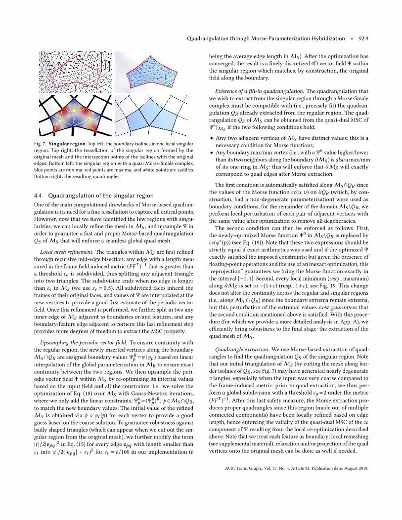
Fig. 7. Singular region. Top left: the boundary isolines in one local singularregion. Top right: the tessellation of the singular region formed by theoriginal mesh and the intersection points of the isolines with the originaledges. Bottom left: the singular region with a quasi Morse-Smale complex,blue points are minima, red points are maxima, and white points are saddles.Bottom right: the resulting quadrangles.
4.4 Quadrangulation of the singular regionOne of the main computational drawbacks of Morse-based quadran-
gulation is its need for a fine tessellation to capture all critical points.
However, now that we have identified the few regions with singu-
larities, we can locally refine the mesh inMS , and upsample Ψ in
order to guarantee a fast and proper Morse-based quadrangulation
QS ofMS that will enforce a seamless global quad mesh.
Local mesh refinement. The triangles withinMS are first refined
through recursive mid-edge bisection: any edge with a length mea-
sured in the frame field induced metric (FFT )−1that is greater than
a threshold εe is subdivided, thus splitting any adjacent triangle
into two triangles. The subdivision ends when no edge is longer
than εe inMS (we use εe = 0.5). All subdivided faces inherit the
frames of their original faces, and values of Ψ are interpolated at the
new vertices to provide a good first estimate of the periodic vector
field. Once this refinement is performed, we further split in two any
inner edge ofMS adjacent to boundaries or/and features, and any
boundary/feature edge adjacent to corners: this last refinement step
provides more degrees of freedom to extract the MSC properly.
Upsampling the periodic vector field. To ensure continuity with
the regular region, the newly inserted vertices along the boundary
MS ∩QR are assigned boundary values ΨRp =ψ (φp ) based on linear
interpolation of the global parameterization inMR to ensure exact
continuity between the two regions. We then upsample the peri-
odic vector field Ψ withinMS by re-optimizing its internal values
based on the input field and all the constraints, i.e., we solve the
optimization of Eq. (18) overMS with Gauss-Newton iterations,
where we only add the linear constraints, Ψ0
p = (Ψ0
p )R , p ∈MS∩QR ,
to match the new boundary values. The initial value of the refined
MS is obtained via ψ ◦ φt (p) for each vertex to provide a good
guess based on the coarse solution. To guarantee robustness against
badly shaped triangles (which can appear when we cut out the sin-
gular region from the original mesh), we further modify the term
|t |/2|epq |2 in Eq. (15) for every edge epq with length smaller than
εs into |t |/2(|epq | + εs )2 for εs = e/100 in our implementation (e
being the average edge length inMS ). After the optimization has
converged, the result is a finely-discretized 4D vector field Ψ within
the singular region which matches, by construction, the original
field along the boundary.
Existence of a fill-in quadrangulation. The quadrangulation that
we wish to extract from the singular region through a Morse-Smale
complex must be compatible with (i.e., precisely fit) the quadran-
gulation QR already extracted from the regular region. The quad-
rangulation QS ofMS can be obtained from the quasi-dual MSC of
Ψ0 |MS if the two following conditions hold:
• Any two adjacent vertices ofMS have distinct values: this is a
necessary condition for Morse functions;
• Any boundary max/min vertex (i.e., with a Ψ0value higher/lower
than its two neighbors along the boundary ∂MS ) is also amax/min
of its one-ring inMS : this will enforce that ∂MS will exactly
correspond to quad edges after Morse extraction.
The first condition is automatically satisfied alongMS∩QR since
the values of the Morse function cc(u,v) on ∂QR (which, by con-
struction, had a non-degenerate parameterization) were used as
boundary conditions; for the remainder of the domainMS \QR , we
perform local perturbation of each pair of adjacent vertices with
the same value after optimization to remove all degeneracies.
The second condition can then be enforced as follows. First,
the newly-optimized Morse function Ψ0inMS \QR is replaced by
cc(φ∗(p)) (see Eq. (19)). Note that these two expressions should be
strictly equal if exact arithmetics was used and if the optimized Ψexactly satisfied the imposed constraints; but given the presence of
floating-point operations and the use of an inexact optimization, this
“reprojection” guarantees we bring the Morse function exactly in
the interval [−1, 1]. Second, every local minimum (resp., maximum)
along ∂MS is set to −(1+ε) (resp., 1+ε), see Fig. 19. This changedoes not alter the continuity across the regular and singular regions
(i.e., alongMS ∩QR ) since the boundary extrema remain extrema;
but this perturbation of the extremal values now guarantees thatthe second condition mentioned above is satisfied. With this proce-
dure (for which we provide a more detailed analysis in App. A), we
efficiently bring robustness to the final stage: the extraction of the
quad mesh ofMS .
Quadrangle extraction. We use Morse-based extraction of quad-
rangles to find the quadrangulation QS of the singular region. Note
that our initial triangulation ofMS (by cutting the mesh along bor-
der isolines ofQR , see Fig. 7) may have generated nearly degenerate
triangles, especially when the input was very coarse compared to
the frame-induced metric; prior to quad extraction, we thus per-
form a global subdivision with a threshold εд =2 under the metric
(FFT )−1. After this last safety measure, the Morse extraction pro-
duces proper quadrangles since this region (made out of multiple
connected components) have been locally refined based on edge
length, hence enforcing the validity of the quasi-dual MSC of the cccomponent of Ψ resulting from the local re-optimization described
above. Note that we treat each feature as boundary; local remeshing
(see supplemental material), relaxation and/or projection of the quad
vertices onto the original mesh can be done as well if needed.
ACM Trans. Graph., Vol. 37, No. 4, Article 92. Publication date: August 2018.
92:10 • Fang, X. et al.
0.3 0.60
20
40
60
0.3 0.60
20
40
60
0.3 0.60
20
40
60
0.3 0.60
20
40
60
ave 0.16 ave 0.13 ave 0.16 ave 0.11
MIQ PGP+ Wave+ Ours
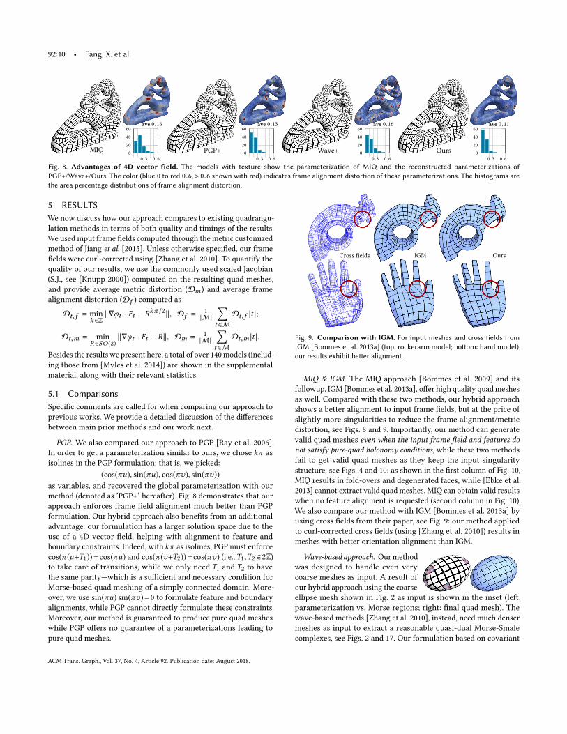
Fig. 8. Advantages of 4D vector field. The models with texture show the parameterization of MIQ and the reconstructed parameterizations ofPGP+/Wave+/Ours. The color (blue 0 to red 0.6,> 0.6 shown with red) indicates frame alignment distortion of these parameterizations. The histograms arethe area percentage distributions of frame alignment distortion.
5 RESULTSWe now discuss how our approach compares to existing quadrangu-
lation methods in terms of both quality and timings of the results.
We used input frame fields computed through the metric customized
method of Jiang et al. [2015]. Unless otherwise specified, our frame
fields were curl-corrected using [Zhang et al. 2010]. To quantify the
quality of our results, we use the commonly used scaled Jacobian
(S.J., see [Knupp 2000]) computed on the resulting quad meshes,
and provide average metric distortion (Dm ) and average frame
alignment distortion (Df ) computed as
Dt,f = min
k ∈Z∥∇φt · Ft − R
kπ /2∥, Df =1
|M |
∑t ∈M
Dt,f |t |;
Dt,m = min
R∈SO (2)∥∇φt · Ft − R∥, Dm =
1
|M |
∑t ∈M
Dt,m |t |.
Besides the results we present here, a total of over 140models (includ-
ing those from [Myles et al. 2014]) are shown in the supplemental
material, along with their relevant statistics.
5.1 ComparisonsSpecific comments are called for when comparing our approach to
previous works. We provide a detailed discussion of the differences
between main prior methods and our work next.
PGP. We also compared our approach to PGP [Ray et al. 2006].
In order to get a parameterization similar to ours, we chose kπ as
isolines in the PGP formulation; that is, we picked:
(cos(πu), sin(πu), cos(πv), sin(πv))
as variables, and recovered the global parameterization with our
method (denoted as ’PGP+’ hereafter). Fig. 8 demonstrates that our
approach enforces frame field alignment much better than PGP
formulation. Our hybrid approach also benefits from an additional
advantage: our formulation has a larger solution space due to the
use of a 4D vector field, helping with alignment to feature and
boundary constraints. Indeed, with kπ as isolines, PGP must enforce
cos(π (u+T1))=cos(πu) and cos(π (v+T2))=cos(πv) (i.e.,T1,T2 ∈2Z)to take care of transitions, while we only need T1 and T2 to have
the same parity—which is a sufficient and necessary condition for
Morse-based quad meshing of a simply connected domain. More-
over, we use sin(πu) sin(πv)=0 to formulate feature and boundary
alignments, while PGP cannot directly formulate these constraints.
Moreover, our method is guaranteed to produce pure quad meshes
while PGP offers no guarantee of a parameterizations leading to
pure quad meshes.
Cross fields OursIGM
Fig. 9. Comparison with IGM. For input meshes and cross fields fromIGM [Bommes et al. 2013a] (top: rockerarm model; bottom: hand model),our results exhibit better alignment.
MIQ & IGM. The MIQ approach [Bommes et al. 2009] and its
followup, IGM [Bommes et al. 2013a], offer high quality quadmeshes
as well. Compared with these two methods, our hybrid approach
shows a better alignment to input frame fields, but at the price of
slightly more singularities to reduce the frame alignment/metric
distortion, see Figs. 8 and 9. Importantly, our method can generate
valid quad meshes even when the input frame field and features donot satisfy pure-quad holonomy conditions, while these two methods
fail to get valid quad meshes as they keep the input singularity
structure, see Figs. 4 and 10: as shown in the first column of Fig. 10,
MIQ results in fold-overs and degenerated faces, while [Ebke et al.
2013] cannot extract valid quad meshes. MIQ can obtain valid results
when no feature alignment is requested (second column in Fig. 10).
We also compare our method with IGM [Bommes et al. 2013a] by
using cross fields from their paper, see Fig. 9: our method applied
to curl-corrected cross fields (using [Zhang et al. 2010]) results in
meshes with better orientation alignment than IGM.
Wave-based approach. Ourmethod
was designed to handle even very
coarse meshes as input. A result of
our hybrid approach using the coarse
ellipse mesh shown in Fig. 2 as input is shown in the inset (left:
parameterization vs. Morse regions; right: final quad mesh). The
wave-based methods [Zhang et al. 2010], instead, need much denser
meshes as input to extract a reasonable quasi-dual Morse-Smale
complexes, see Figs. 2 and 17. Our formulation based on covariant
ACM Trans. Graph., Vol. 37, No. 4, Article 92. Publication date: August 2018.
Quadrangulation through Morse-Parameterization Hybridization • 92:11
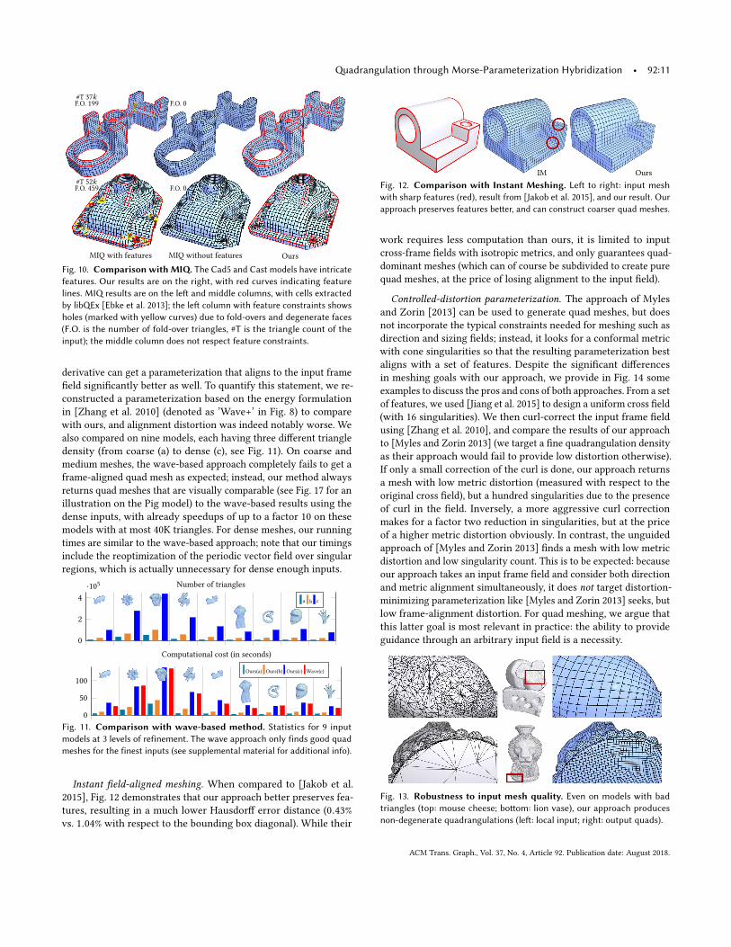
MIQ with features MIQ without features Ours
#T 37kF.O. 199
#T 52kF.O. 459
F.O. 0
F.O. 0
Fig. 10. Comparison with MIQ. The Cad5 and Cast models have intricatefeatures. Our results are on the right, with red curves indicating featurelines. MIQ results are on the left and middle columns, with cells extractedby libQEx [Ebke et al. 2013]; the left column with feature constraints showsholes (marked with yellow curves) due to fold-overs and degenerate faces(F.O. is the number of fold-over triangles, #T is the triangle count of theinput); the middle column does not respect feature constraints.
derivative can get a parameterization that aligns to the input frame
field significantly better as well. To quantify this statement, we re-
constructed a parameterization based on the energy formulation
in [Zhang et al. 2010] (denoted as ’Wave+’ in Fig. 8) to compare
with ours, and alignment distortion was indeed notably worse. We
also compared on nine models, each having three different triangle
density (from coarse (a) to dense (c), see Fig. 11). On coarse and
medium meshes, the wave-based approach completely fails to get a
frame-aligned quad mesh as expected; instead, our method always
returns quad meshes that are visually comparable (see Fig. 17 for an
illustration on the Pig model) to the wave-based results using the
dense inputs, with already speedups of up to a factor 10 on these
models with at most 40K triangles. For dense meshes, our running
times are similar to the wave-based approach; note that our timings
include the reoptimization of the periodic vector field over singular
regions, which is actually unnecessary for dense enough inputs.
0
2
4
·105 Number of triangles
a b c
0
50
100
Computational cost (in seconds)
Ours(a) Ours(b) Ours(c) Wave(c)
Fig. 11. Comparison with wave-based method. Statistics for 9 inputmodels at 3 levels of refinement. The wave approach only finds good quadmeshes for the finest inputs (see supplemental material for additional info).
Instant field-aligned meshing. When compared to [Jakob et al.
2015], Fig. 12 demonstrates that our approach better preserves fea-
tures, resulting in a much lower Hausdorff error distance (0.43%
vs. 1.04% with respect to the bounding box diagonal). While their
IM Ours
Fig. 12. Comparison with Instant Meshing. Left to right: input meshwith sharp features (red), result from [Jakob et al. 2015], and our result. Ourapproach preserves features better, and can construct coarser quad meshes.
work requires less computation than ours, it is limited to input
cross-frame fields with isotropic metrics, and only guarantees quad-
dominant meshes (which can of course be subdivided to create pure
quad meshes, at the price of losing alignment to the input field).
Controlled-distortion parameterization. The approach of Myles
and Zorin [2013] can be used to generate quad meshes, but does
not incorporate the typical constraints needed for meshing such as
direction and sizing fields; instead, it looks for a conformal metric
with cone singularities so that the resulting parameterization best
aligns with a set of features. Despite the significant differences
in meshing goals with our approach, we provide in Fig. 14 some
examples to discuss the pros and cons of both approaches. From a set
of features, we used [Jiang et al. 2015] to design a uniform cross field
(with 16 singularities). We then curl-correct the input frame field
using [Zhang et al. 2010], and compare the results of our approach
to [Myles and Zorin 2013] (we target a fine quadrangulation density
as their approach would fail to provide low distortion otherwise).
If only a small correction of the curl is done, our approach returns
a mesh with low metric distortion (measured with respect to the
original cross field), but a hundred singularities due to the presence
of curl in the field. Inversely, a more aggressive curl correction
makes for a factor two reduction in singularities, but at the price
of a higher metric distortion obviously. In contrast, the unguided
approach of [Myles and Zorin 2013] finds a mesh with low metric
distortion and low singularity count. This is to be expected: because
our approach takes an input frame field and consider both direction
and metric alignment simultaneously, it does not target distortion-minimizing parameterization like [Myles and Zorin 2013] seeks, but
low frame-alignment distortion. For quad meshing, we argue that
this latter goal is most relevant in practice: the ability to provide
guidance through an arbitrary input field is a necessity.
Fig. 13. Robustness to input mesh quality. Even on models with badtriangles (top: mouse cheese; bottom: lion vase), our approach producesnon-degenerate quadrangulations (left: local input; right: output quads).
ACM Trans. Graph., Vol. 37, No. 4, Article 92. Publication date: August 2018.
92:12 • Fang, X. et al.
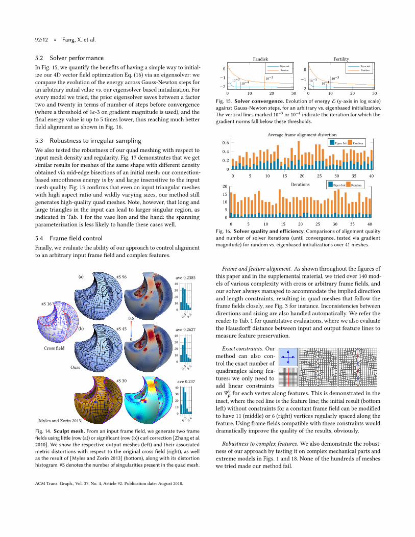
5.2 Solver performanceIn Fig. 15, we quantify the benefits of having a simple way to initial-
ize our 4D vector field optimization Eq. (16) via an eigensolver: we
compare the evolution of the energy across Gauss-Newton steps for
an arbitrary initial value vs. our eigensolver-based initialization. For
every model we tried, the prior eigensolver saves between a factor
two and twenty in terms of number of steps before convergence
(where a threshold of 1e-3 on gradient magnitude is used), and the
final energy value is up to 5 times lower, thus reaching much better
field alignment as shown in Fig. 16.
5.3 Robustness to irregular samplingWe also tested the robustness of our quad meshing with respect to
input mesh density and regularity. Fig. 17 demonstrates that we get
similar results for meshes of the same shape with different density
obtained via mid-edge bisections of an initial mesh: our connection-
based smoothness energy is by and large insensitive to the input
mesh quality. Fig. 13 confirms that even on input triangular meshes
with high aspect ratio and wildly varying sizes, our method still
generates high-quality quad meshes. Note, however, that long and
large triangles in the input can lead to larger singular region, as
indicated in Tab. 1 for the vase lion and the hand: the spanning
parameterization is less likely to handle these cases well.
5.4 Frame field controlFinally, we evaluate the ability of our approach to control alignment
to an arbitrary input frame field and complex features.
Cross field
0.3
0.6
0
10
20
30
40
ave 0.2385
0.3
0.6
0
10
20
30
40
ave 0.2627
0.3
0.6
0
10
20
30
40
ave 0.237
[Myles and Zorin 2013]
(a)
(b)
Ours
0
0.6
#S 30
#S 96
#S 45
#S 16
Fig. 14. Sculpt mesh. From an input frame field, we generate two framefields using little (row (a)) or significant (row (b)) curl correction [Zhang et al.2010]. We show the respective output meshes (left) and their associatedmetric distortions with respect to the original cross field (right), as wellas the result of [Myles and Zorin 2013] (bottom), along with its distortionhistogram. #S denotes the number of singularities present in the quad mesh.
0 10 20 30
−2
−1
0
Fandisk
Eigen init
Random
0 10 20 30
−2
−1
0
Fertility
Eigen init
Random
10−3
10−4
10−3
10−3
10−4
10−3
Fig. 15. Solver convergence. Evolution of energy E (y-axis in log scale)against Gauss-Newton steps, for an arbitrary vs. eigenbased initialization.The vertical lines marked 10
−3 or 10−4 indicate the iteration for which the
gradient norms fall below these thresholds.
0 5 10 15 20 25 30 35 40
0
0.2
0.4
0.6
Average frame alignment distortion
Eigen Init Random
0 5 10 15 20 25 30 35 40
0
5
10
15
20Iterations Eigen Init Random
Fig. 16. Solver quality and efficiency. Comparisons of alignment qualityand number of solver iterations (until convergence, tested via gradientmagnitude) for random vs. eigenbased initializations over 41 meshes.
Frame and feature alignment. As shown throughout the figures of
this paper and in the supplemental material, we tried over 140 mod-
els of various complexity with cross or arbitrary frame fields, and
our solver always managed to accommodate the implied direction
and length constraints, resulting in quad meshes that follow the
frame fields closely, see Fig. 3 for instance. Inconsistencies between
directions and sizing are also handled automatically. We refer the
reader to Tab. 1 for quantitative evaluations, where we also evaluate
the Hausdorff distance between input and output feature lines to
measure feature preservation.
Exact constraints. Ourmethod can also con-
trol the exact number of
quadrangles along fea-
tures: we only need to
add linear constraints
on Ψ0
p for each vertex along features. This is demonstrated in the
inset, where the red line is the feature line; the initial result (bottom
left) without constraints for a constant frame field can be modified
to have 11 (middle) or 6 (right) vertices regularly spaced along the
feature. Using frame fields compatible with these constraints would
dramatically improve the quality of the results, obviously.
Robustness to complex features. We also demonstrate the robust-
ness of our approach by testing it on complex mechanical parts and
extreme models in Figs. 1 and 18. None of the hundreds of meshes
we tried made our method fail.
ACM Trans. Graph., Vol. 37, No. 4, Article 92. Publication date: August 2018.
Quadrangulation through Morse-Parameterization Hybridization • 92:13
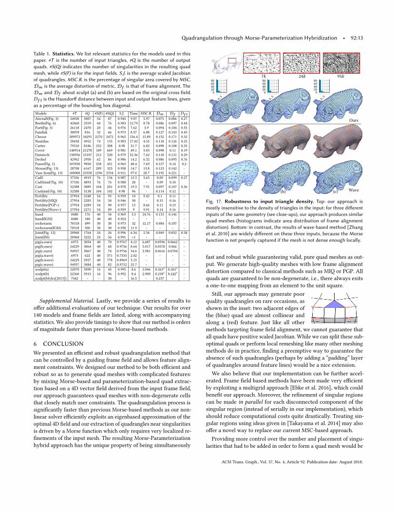
Table 1. Statistics. We list relevant statistics for the models used in thispaper. #T is the number of input triangles, #Q is the number of outputquads. #S(Q) indicates the number of singularities in the resulting quadmesh, while #S(F) is for the input fields. S.J. is the average scaled Jacobianof quadrangles. MSC.R. is the percentage of singular area covered by MSC.Dm is the average distortion of metric, Df is that of frame alignment. TheDm and Df about sculpt (a) and (b) are based on the original cross field.Df l is the Hausdorff distance between input and output feature lines, givenas a percentage of the bounding box diagonal.
Models #T #Q #S(F) #S(Q) S.J. Time MSC.R. Dm Df Df lAircraft(Fig. 3) 24920 3807 54 87 0.945 9.07 5.97 0.075 0.086 0.27
Beetle(Fig. 6) 42468 2559 60 76 0.983 12.79 8.78 0.086 0.097 0.44
Part(Fig. 3) 26118 2470 20 44 0.976 7.62 3.9 0.094 0.104 0.55
Fandisk 30078 816 32 66 0.973 8.57 6.88 0.127 0.143 0.45
Cheese 389972 34291 2270 2472 0.965 156.4 15.89 0.152 0.171 0.32
Nautilus 50438 4952 74 155 0.983 17.02 4.55 0.118 0.126 0.25
Carter 79310 8186 252 308 0.98 31.7 6.82 0.098 0.108 0.35
Cover 140914 21278 189 669 0.981 49.1 5.03 0.098 0.11 0.19
Datatech 130956 15107 212 520 0.979 52.36 7.62 0.118 0.131 0.29
Deckel 42962 2950 62 86 0.986 14.2 6.32 0.086 0.095 0.76
Fusee(Fig. 1) 107050 9050 258 451 0.965 40.4 7.69 0.127 0.14 0.2
Mouse(Fig. 13) 28708 6167 209 323 0.958 14.7 13.8 0.123 0.142 -
Vase-lion(Fig. 13) 100000 23358 1296 2534 0.911 97.0 28.7 0.192 0.221 -
Cad5 37336 4919 76 134 0.987 12.3 5.63 0.09 0.099 0.27
Cad5(mid Fig. 10) 37336 4893 76 76 0.988 28 - 0.09 0.10
Cast 52388 5089 104 201 0.978 19.3 7.91 0.097 0.107 0.36
Cast(mid Fig. 10) 52388 5138 104 102 0.98 96 - 0.114 0.12 -
Fertility 27954 2248 54 92 0.959 10 9.43 0.1 0.11 -
Fertility(MIQ) 27954 2283 54 54 0.946 30 - 0.15 0.16 -
Fertility(PGP+) 27954 2289 54 90 0.957 15 8.66 0.11 0.13 -
Fertility(Wave+) 27954 2271 54 89 0.959 9 9.91 0.14 0.16 -
hand 8480 176 40 34 0.969 3.5 24.76 0.133 0.146 -
hand(IGM) 8480 180 40 40 0.924 - - - - -
rockerarm 70318 499 30 38 0.973 32 12.17 0.084 0.107 -
rockerarm(IGM) 70318 500 30 30 0.958 11.9 - - - -
Joint(Fig. 12) 20968 1764 24 26 0.996 6.54 2.34 0.049 0.052 0.38
Joint(IM) 20968 3222 24 56 0.991 <1 - - - -
pig(a,ours) 6973 3054 40 70 0.9767 4.12 6.687 0.0596 0.0662 -
pig(b,ours) 24229 3064 40 68 0.9756 8.64 5.017 0.0578 0.066 -
pig(c,ours) 94937 3067 40 74 0.9756 34.6 3.981 0.0616 0.0704 -
pig(a,wave) 6973 622 40 371 0.7333 2.02 - - - -
pig(b,wave) 24229 2927 40 778 0.8969 5.15 - - - -
pig(c,wave) 94937 3084 40 82 0.9752 25.7 - - - -
sculpt(a) 22070 5890 16 45 0.995 8.6 2.046 0.263* 0.265* -
sculpt(b) 22360 5913 16 96 0.992 8.4 2.909 0.238* 0.242* -
sculpt(Myles[2013]) 7342 - - 30 - 16.5 - 0.237 - -
Supplemental Material. Lastly, we provide a series of results tooffer additional evaluations of our technique. Our results for over
140 models and frame fields are listed, along with accompanying
statistics. We also provide timings to show that our method is orders
of magnitude faster than previous Morse-based methods.
6 CONCLUSIONWe presented an efficient and robust quadrangulation method that
can be controlled by a guiding frame field and allows feature align-
ment constraints. We designed our method to be both efficient and
robust so as to generate quad meshes with complicated features:
by mixing Morse-based and parameterization-based quad extrac-
tion based on a 4D vector field derived from the input frame field,
our approach guarantees quad meshes with non-degenerate cells
that closely match user constraints. The quadrangulation process is
significantly faster than previous Morse-based methods as our non-
linear solver efficiently exploits an eigenbased approximation of the
optimal 4D field and our extraction of quadrangles near singularities
is driven by a Morse function which only requires very localized re-
finements of the input mesh. The resulting Morse-Parameterization
hybrid approach has the unique property of being simultaneously
7k 24k 95k
0.3
0
20
40
60
80
0.3
0
20
40
60
80
0.3
0
20
40
60
80
Ours
Wave(a) (b) (c)
Fig. 17. Robustness to input triangle density. Top: our approach ismostly insensitive to the density of triangles in the input: for three differentinputs of the same geometry (see close-ups), our approach produces similarquad meshes (histograms indicate area distribution of frame alignmentdistortion). Bottom: in contrast, the results of wave-based method [Zhanget al. 2010] are widely different on these three inputs, because the Morsefunction is not properly captured if the mesh is not dense enough locally.
fast and robust while guaranteeing valid, pure quad meshes as out-
put. We generate high-quality meshes with low frame alignment
distortion compared to classical methods such as MIQ or PGP. All
quads are guaranteed to be non-degenerate, i.e., there always exits
a one-to-one mapping from an element to the unit square.
Still, our approach may generate poor
quality quadrangles on rare occasions, as
shown in the inset: two adjacent edges of
the (blue) quad are almost collinear and
along a (red) feature. Just like all other
methods targeting frame field alignment, we cannot guarantee that
all quads have positive scaled Jacobian. While we can split these sub-
optimal quads or perform local remeshing like many other meshing
methods do in practice, finding a preemptive way to guarantee the
absence of such quadrangles (perhaps by adding a “padding” layer
of quadrangles around feature lines) would be a nice extension.
We also believe that our implementation can be further accel-
erated. Frame field based methods have been made very efficient
by exploiting a multigrid approach [Ebke et al. 2016], which could
benefit our approach. Moreover, the refinement of singular regions
can be made in parallel for each disconnected component of the
singular region (instead of serially in our implementation), which
should reduce computational costs quite drastically. Treating sin-
gular regions using ideas given in [Takayama et al. 2014] may also
offer a novel way to replace our current MSC-based approach.
Providing more control over the number and placement of singu-
larities that had to be added in order to form a quad mesh would be
ACM Trans. Graph., Vol. 37, No. 4, Article 92. Publication date: August 2018.
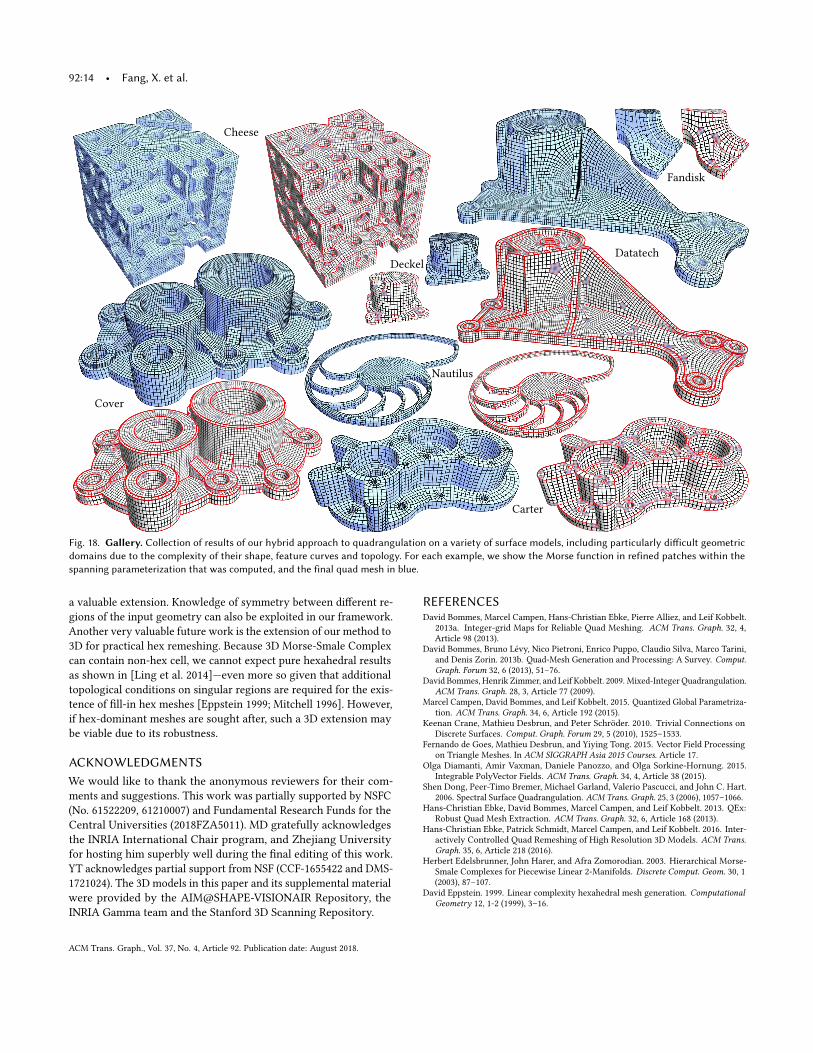
92:14 • Fang, X. et al.
Deckel
Datatech
Fandisk
Cheese
Nautilus
Carter
Cover
Fig. 18. Gallery. Collection of results of our hybrid approach to quadrangulation on a variety of surface models, including particularly difficult geometricdomains due to the complexity of their shape, feature curves and topology. For each example, we show the Morse function in refined patches within thespanning parameterization that was computed, and the final quad mesh in blue.
a valuable extension. Knowledge of symmetry between different re-
gions of the input geometry can also be exploited in our framework.
Another very valuable future work is the extension of our method to
3D for practical hex remeshing. Because 3D Morse-Smale Complex
can contain non-hex cell, we cannot expect pure hexahedral results
as shown in [Ling et al. 2014]—even more so given that additional
topological conditions on singular regions are required for the exis-
tence of fill-in hex meshes [Eppstein 1999; Mitchell 1996]. However,
if hex-dominant meshes are sought after, such a 3D extension may
be viable due to its robustness.
ACKNOWLEDGMENTSWe would like to thank the anonymous reviewers for their com-
ments and suggestions. This work was partially supported by NSFC
(No. 61522209, 61210007) and Fundamental Research Funds for the
Central Universities (2018FZA5011). MD gratefully acknowledges
the INRIA International Chair program, and Zhejiang University
for hosting him superbly well during the final editing of this work.
YT acknowledges partial support from NSF (CCF-1655422 and DMS-
1721024). The 3D models in this paper and its supplemental material
were provided by the AIM@SHAPE-VISIONAIR Repository, the
INRIA Gamma team and the Stanford 3D Scanning Repository.
REFERENCESDavid Bommes, Marcel Campen, Hans-Christian Ebke, Pierre Alliez, and Leif Kobbelt.
2013a. Integer-grid Maps for Reliable Quad Meshing. ACM Trans. Graph. 32, 4,Article 98 (2013).
David Bommes, Bruno Lévy, Nico Pietroni, Enrico Puppo, Claudio Silva, Marco Tarini,
and Denis Zorin. 2013b. Quad-Mesh Generation and Processing: A Survey. Comput.Graph. Forum 32, 6 (2013), 51–76.
David Bommes, Henrik Zimmer, and Leif Kobbelt. 2009. Mixed-Integer Quadrangulation.
ACM Trans. Graph. 28, 3, Article 77 (2009).Marcel Campen, David Bommes, and Leif Kobbelt. 2015. Quantized Global Parametriza-
tion. ACM Trans. Graph. 34, 6, Article 192 (2015).Keenan Crane, Mathieu Desbrun, and Peter Schröder. 2010. Trivial Connections on
Discrete Surfaces. Comput. Graph. Forum 29, 5 (2010), 1525–1533.
Fernando de Goes, Mathieu Desbrun, and Yiying Tong. 2015. Vector Field Processing
on Triangle Meshes. In ACM SIGGRAPH Asia 2015 Courses. Article 17.Olga Diamanti, Amir Vaxman, Daniele Panozzo, and Olga Sorkine-Hornung. 2015.
Integrable PolyVector Fields. ACM Trans. Graph. 34, 4, Article 38 (2015).Shen Dong, Peer-Timo Bremer, Michael Garland, Valerio Pascucci, and John C. Hart.
2006. Spectral Surface Quadrangulation. ACM Trans. Graph. 25, 3 (2006), 1057–1066.Hans-Christian Ebke, David Bommes, Marcel Campen, and Leif Kobbelt. 2013. QEx:
Robust Quad Mesh Extraction. ACM Trans. Graph. 32, 6, Article 168 (2013).Hans-Christian Ebke, Patrick Schmidt, Marcel Campen, and Leif Kobbelt. 2016. Inter-
actively Controlled Quad Remeshing of High Resolution 3D Models. ACM Trans.Graph. 35, 6, Article 218 (2016).
Herbert Edelsbrunner, John Harer, and Afra Zomorodian. 2003. Hierarchical Morse-
Smale Complexes for Piecewise Linear 2-Manifolds. Discrete Comput. Geom. 30, 1(2003), 87–107.
David Eppstein. 1999. Linear complexity hexahedral mesh generation. ComputationalGeometry 12, 1-2 (1999), 3–16.
ACM Trans. Graph., Vol. 37, No. 4, Article 92. Publication date: August 2018.
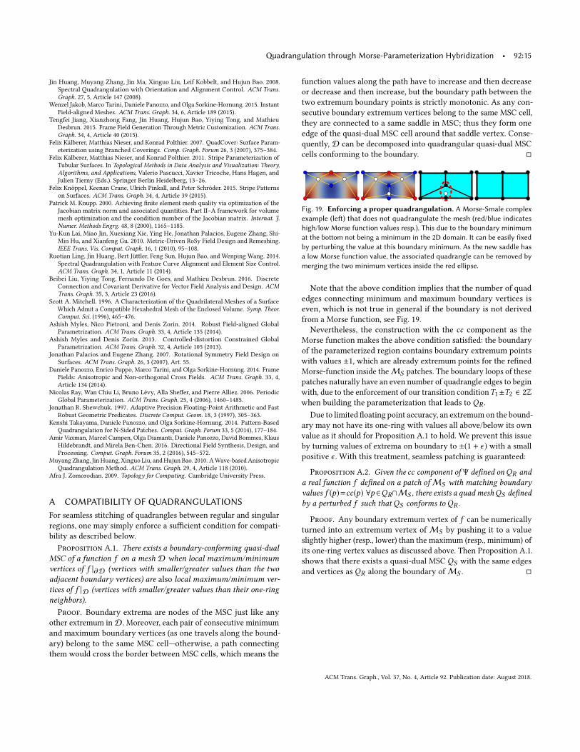
Quadrangulation through Morse-Parameterization Hybridization • 92:15
Jin Huang, Muyang Zhang, Jin Ma, Xinguo Liu, Leif Kobbelt, and Hujun Bao. 2008.
Spectral Quadrangulation with Orientation and Alignment Control. ACM Trans.Graph. 27, 5, Article 147 (2008).
Wenzel Jakob, Marco Tarini, Daniele Panozzo, and Olga Sorkine-Hornung. 2015. Instant
Field-aligned Meshes. ACM Trans. Graph. 34, 6, Article 189 (2015).Tengfei Jiang, Xianzhong Fang, Jin Huang, Hujun Bao, Yiying Tong, and Mathieu
Desbrun. 2015. Frame Field Generation Through Metric Customization. ACM Trans.Graph. 34, 4, Article 40 (2015).
Felix Kälberer, Matthias Nieser, and Konrad Polthier. 2007. QuadCover: Surface Param-
eterization using Branched Coverings. Comp. Graph. Forum 26, 3 (2007), 375–384.
Felix Kälberer, Matthias Nieser, and Konrad Polthier. 2011. Stripe Parameterization of
Tubular Surfaces. In Topological Methods in Data Analysis and Visualization: Theory,Algorithms, and Applications, Valerio Pascucci, Xavier Tricoche, Hans Hagen, and
Julien Tierny (Eds.). Springer Berlin Heidelberg, 13–26.
Felix Knöppel, Keenan Crane, Ulrich Pinkall, and Peter Schröder. 2015. Stripe Patterns
on Surfaces. ACM Trans. Graph. 34, 4, Article 39 (2015).Patrick M. Knupp. 2000. Achieving finite element mesh quality via optimization of the
Jacobian matrix norm and associated quantities. Part II–A framework for volume
mesh optimization and the condition number of the Jacobian matrix. Internat. J.Numer. Methods Engrg. 48, 8 (2000), 1165–1185.
Yu-Kun Lai, Miao Jin, Xuexiang Xie, Ying He, Jonathan Palacios, Eugene Zhang, Shi-
Min Hu, and Xianfeng Gu. 2010. Metric-Driven RoSy Field Design and Remeshing.
IEEE Trans. Vis. Comput. Graph. 16, 1 (2010), 95–108.Ruotian Ling, Jin Huang, Bert Jüttler, Feng Sun, Hujun Bao, and Wenping Wang. 2014.
Spectral Quadrangulation with Feature Curve Alignment and Element Size Control.
ACM Trans. Graph. 34, 1, Article 11 (2014).Beibei Liu, Yiying Tong, Fernando De Goes, and Mathieu Desbrun. 2016. Discrete
Connection and Covariant Derivative for Vector Field Analysis and Design. ACMTrans. Graph. 35, 3, Article 23 (2016).
Scott A. Mitchell. 1996. A Characterization of the Quadrilateral Meshes of a Surface
Which Admit a Compatible Hexahedral Mesh of the Enclosed Volume. Symp. Theor.Comput. Sci. (1996), 465–476.
Ashish Myles, Nico Pietroni, and Denis Zorin. 2014. Robust Field-aligned Global
Parametrization. ACM Trans. Graph. 33, 4, Article 135 (2014).Ashish Myles and Denis Zorin. 2013. Controlled-distortion Constrained Global
Parametrization. ACM Trans. Graph. 32, 4, Article 105 (2013).Jonathan Palacios and Eugene Zhang. 2007. Rotational Symmetry Field Design on
Surfaces. ACM Trans. Graph. 26, 3 (2007), Art. 55.Daniele Panozzo, Enrico Puppo, Marco Tarini, and Olga Sorkine-Hornung. 2014. Frame
Fields: Anisotropic and Non-orthogonal Cross Fields. ACM Trans. Graph. 33, 4,Article 134 (2014).
Nicolas Ray, Wan Chiu Li, Bruno Lévy, Alla Sheffer, and Pierre Alliez. 2006. Periodic
Global Parameterization. ACM Trans. Graph. 25, 4 (2006), 1460–1485.Jonathan R. Shewchuk. 1997. Adaptive Precision Floating-Point Arithmetic and Fast
Robust Geometric Predicates. Discrete Comput. Geom. 18, 3 (1997), 305–363.Kenshi Takayama, Daniele Panozzo, and Olga Sorkine-Hornung. 2014. Pattern-Based
Quadrangulation for N-Sided Patches. Comput. Graph. Forum 33, 5 (2014), 177–184.
Amir Vaxman, Marcel Campen, Olga Diamanti, Daniele Panozzo, David Bommes, Klaus
Hildebrandt, and Mirela Ben-Chen. 2016. Directional Field Synthesis, Design, and
Processing. Comput. Graph. Forum 35, 2 (2016), 545–572.
Muyang Zhang, Jin Huang, Xinguo Liu, andHujun Bao. 2010. AWave-based Anisotropic
Quadrangulation Method. ACM Trans. Graph. 29, 4, Article 118 (2010).Afra J. Zomorodian. 2009. Topology for Computing. Cambridge University Press.
A COMPATIBILITY OF QUADRANGULATIONSFor seamless stitching of quadrangles between regular and singular
regions, one may simply enforce a sufficient condition for compati-
bility as described below.
Proposition A.1. There exists a boundary-conforming quasi-dualMSC of a function f on a mesh D when local maximum/minimumvertices of f |∂D (vertices with smaller/greater values than the twoadjacent boundary vertices) are also local maximum/minimum ver-tices of f |D (vertices with smaller/greater values than their one-ringneighbors).Proof. Boundary extrema are nodes of the MSC just like any
other extremum inD. Moreover, each pair of consecutive minimum
and maximum boundary vertices (as one travels along the bound-
ary) belong to the same MSC cell—otherwise, a path connecting
them would cross the border between MSC cells, which means the
function values along the path have to increase and then decrease
or decrease and then increase, but the boundary path between the
two extremum boundary points is strictly monotonic. As any con-
secutive boundary extremum vertices belong to the same MSC cell,
they are connected to a same saddle in MSC; thus they form one
edge of the quasi-dual MSC cell around that saddle vertex. Conse-
quently, D can be decomposed into quadrangular quasi-dual MSC
cells conforming to the boundary. �
Fig. 19. Enforcing a proper quadrangulation. A Morse-Smale complexexample (left) that does not quadrangulate the mesh (red/blue indicateshigh/low Morse function values resp.). This due to the boundary minimumat the bottom not being a minimum in the 2D domain. It can be easily fixedby perturbing the value at this boundary minimum. As the new saddle hasa low Morse function value, the associated quadrangle can be removed bymerging the two minimum vertices inside the red ellipse.
Note that the above condition implies that the number of quad
edges connecting minimum and maximum boundary vertices is
even, which is not true in general if the boundary is not derived
from a Morse function, see Fig. 19.
Nevertheless, the construction with the cc component as the
Morse function makes the above condition satisfied: the boundary
of the parameterized region contains boundary extremum points
with values ±1, which are already extremum points for the refined
Morse-function inside theMS patches. The boundary loops of these
patches naturally have an even number of quadrangle edges to begin
with, due to the enforcement of our transition conditionT1±T2 ∈ 2Zwhen building the parameterization that leads to QR .
Due to limited floating point accuracy, an extremum on the bound-
ary may not have its one-ring with values all above/below its own
value as it should for Proposition A.1 to hold. We prevent this issue
by turning values of extrema on boundary to ±(1 + ϵ) with a small
positive ϵ . With this treatment, seamless patching is guaranteed:
Proposition A.2. Given the cc component of Ψ defined onQR anda real function f defined on a patch ofMS with matching boundaryvalues f (p)=cc(p) ∀p ∈QR∩MS , there exists a quad meshQS definedby a perturbed f such that QS conforms to QR .
Proof. Any boundary extremum vertex of f can be numerically
turned into an extremum vertex ofMS by pushing it to a value
slightly higher (resp., lower) than the maximum (resp., minimum) of
its one-ring vertex values as discussed above. Then Proposition A.1.
shows that there exists a quasi-dual MSC QS with the same edges
and vertices as QR along the boundary ofMS . �
ACM Trans. Graph., Vol. 37, No. 4, Article 92. Publication date: August 2018.