qrp z-match tuner (40 10m) g8ode · pdf fileqrp z-match tuner (40 –10m) – g8ode...
TRANSCRIPT
QRP Z-MATCH TUNER (40 –10m) – G8ODE
C1a270pF
C2a
270pF
Inductor L1/L2
wound
on red core
20T
50 Ohms
I/P
C1b270pF
C2b
270pF
ANTENNA
14T
10T
6T
Balanced /Unbalanced
Switch
RG174 Coax
TUNING
REACTANCE
COUPLING
L1
L2
PD7MAA
Tuning
Indicator
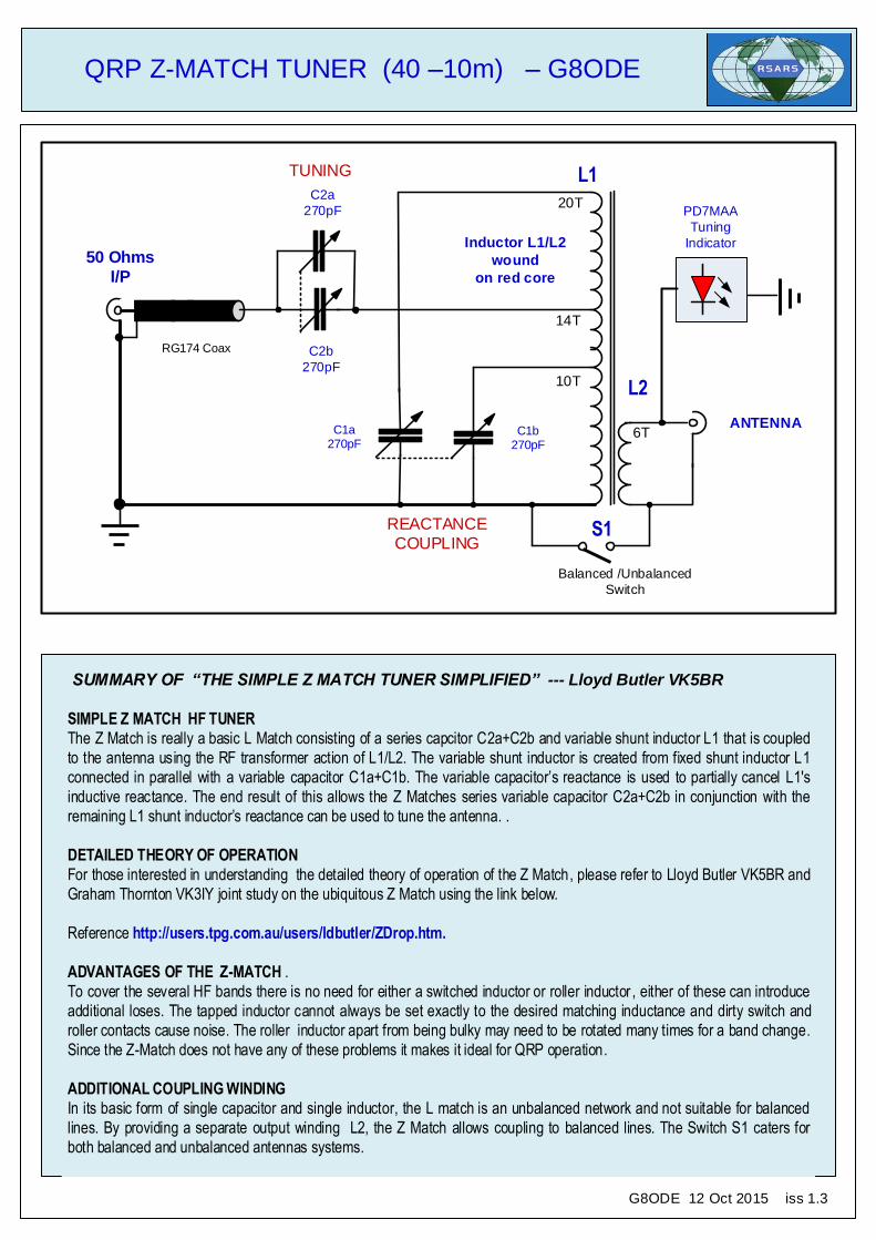
SUMMARY OF “THE SIMPLE Z MATCH TUNER SIMPLIFIED” --- Lloyd Butler VK5BR
SIMPLE Z MATCH HF TUNER
The Z Match is really a basic L Match consisting of a series capcitor C2a+C2b and variable shunt inductor L1 that is coupled
to the antenna using the RF transformer action of L1/L2. The variable shunt inductor is created from fixed shunt inductor L1 connected in parallel with a variable capacitor C1a+C1b. The variable capacitor’s reactance is used to partially cancel L1's
inductive reactance. The end result of this allows the Z Matches series variable capacitor C2a+C2b in conjunction with the
remaining L1 shunt inductor’s reactance can be used to tune the antenna. .
DETAILED THEORY OF OPERATION
For those interested in understanding the detailed theory of operation of the Z Match, please refer to Lloyd Butler VK5BR and
Graham Thornton VK3IY joint study on the ubiquitous Z Match using the link below.
Reference http://users.tpg.com.au/users/ldbutler/ZDrop.htm.
ADVANTAGES OF THE Z-MATCH .
To cover the several HF bands there is no need for either a switched inductor or roller inductor , either of these can introduce additional loses. The tapped inductor cannot always be set exactly to the desired matching inductance and dirty switch and
roller contacts cause noise. The roller inductor apart from being bulky may need to be rotated many times for a band change.
Since the Z-Match does not have any of these problems it makes it ideal for QRP operation.
ADDITIONAL COUPLING WINDING
In its basic form of single capacitor and single inductor, the L match is an unbalanced network and not suitable for balanced
lines. By providing a separate output winding L2, the Z Match allows coupling to balanced lines. The Switch S1 caters for
both balanced and unbalanced antennas systems.
S1
G8ODE 12 Oct 2015 iss 1.3
QRP Z-MATCH TUNER (40 –10m) – G8ODE
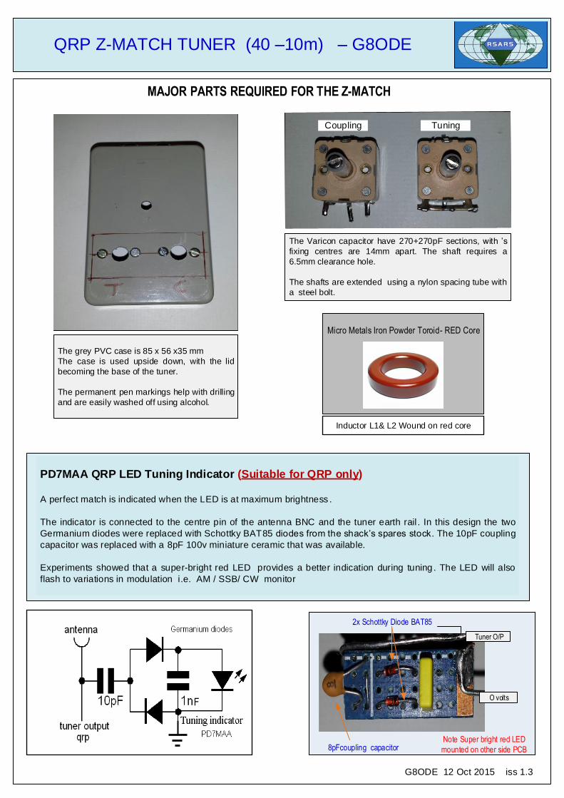
MAJOR PARTS REQUIRED FOR THE Z-MATCH
Micro Metals Iron Powder Toroid- RED Core
The Varicon capacitor have 270+270pF sections, with ’s
fixing centres are 14mm apart. The shaft requires a
6.5mm clearance hole.
The shafts are extended using a nylon spacing tube with
a steel bolt.
Tuner O/P
O volts
Note Super bright red LED
mounted on other side PCB
2x Schottky Diode BAT85
F
Inductor L1& L2 Wound on red core
PD7MAA QRP LED Tuning Indicator (Suitable for QRP only)
A perfect match is indicated when the LED is at maximum brightness .
The indicator is connected to the centre pin of the antenna BNC and the tuner earth rail . In this design the two
Germanium diodes were replaced with Schottky BAT85 diodes from the shack’s spares stock. The 10pF coupling
capacitor was replaced with a 8pF 100v miniature ceramic that was available.
Experiments showed that a super-bright red LED provides a better indication during tuning. The LED will also
flash to variations in modulation i.e. AM / SSB/ CW monitor
The grey PVC case is 85 x 56 x35 mm
The case is used upside down, with the lid
becoming the base of the tuner.
The permanent pen markings help with drilling
and are easily washed off using alcohol.
8pFcoupling capacitor
G8ODE 12 Oct 2015 iss 1.3
TuningCoupling
QRP Z-MATCH TUNER (40 –10m) – G8ODE
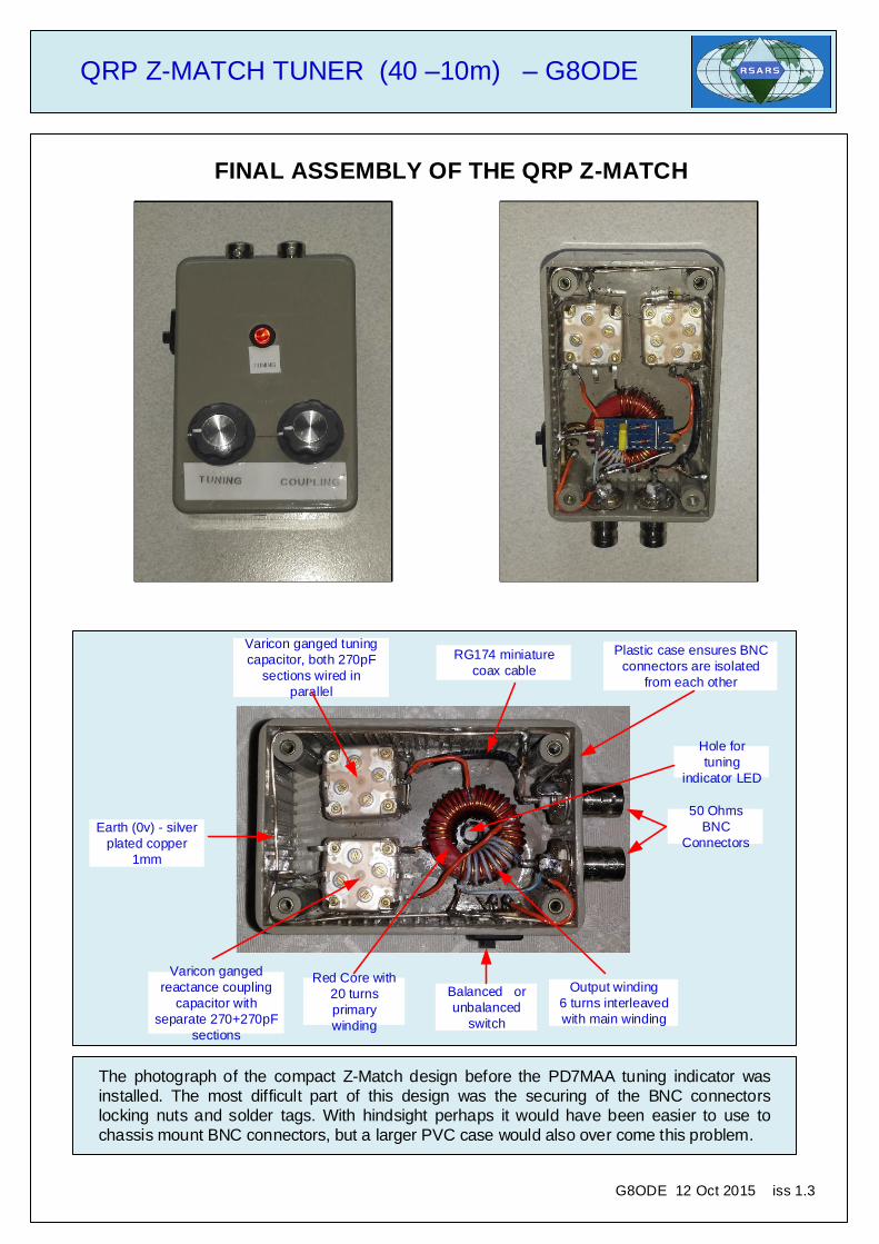
FINAL ASSEMBLY OF THE QRP Z-MATCH
G8ODE 12 Oct 2015 iss 1.3
Earth (0v) - silver
plated copper
1mm
Varicon ganged
reactance coupling
capacitor with
separate 270+270pF
sections
Varicon ganged tuning
capacitor, both 270pF
sections wired in
parallel
Red Core with
20 turns
primary
winding
Output winding
6 turns interleaved
with main winding
RG174 miniature
coax cable
50 Ohms
BNC
Connectors
Plastic case ensures BNC
connectors are isolated
from each other
Hole for
tuning
indicator LED
The photograph of the compact Z-Match design before the PD7MAA tuning indicator was
installed. The most difficult part of this design was the securing of the BNC connectors
locking nuts and solder tags. With hindsight perhaps it would have been easier to use to
chassis mount BNC connectors, but a larger PVC case would also over come this problem.
Balanced or
unbalanced
switch
QRP Z-MATCH TUNER (40 –10m) – G8ODE
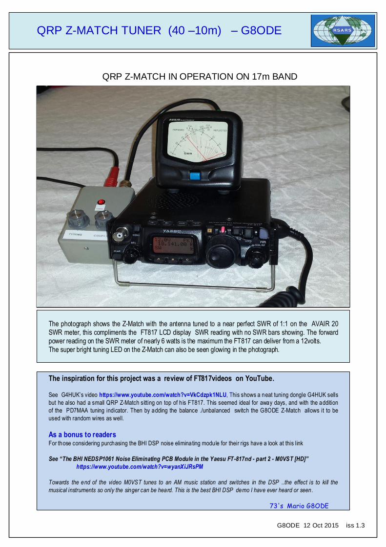
QRP Z-MATCH IN OPERATION ON 17m BAND
The photograph shows the Z-Match with the antenna tuned to a near perfect SWR of 1:1 on the AVAIR 20
SWR meter, this compliments the FT817 LCD display SWR reading with no SWR bars showing. The forward
power reading on the SWR meter of nearly 6 watts is the maximum the FT817 can deliver from a 12volts. The super bright tuning LED on the Z-Match can also be seen glowing in the photograph.
The inspiration for this project was a review of FT817videos on YouTube.
See G4HUK’s video https://www.youtube.com/watch?v=VkCdzpk1NLU, This shows a neat tuning dongle G4HUK sells
but he also had a small QRP Z-Match sitting on top of his FT817. This seemed ideal for away days, and with the addition
of the PD7MAA tuning indicator. Then by adding the balance ./unbalanced switch the G8ODE Z-Match allows it to be
used with random wires as well.
As a bonus to readers For those considering purchasing the BHI DSP noise eliminating module for their rigs have a look at this link
See “The BHI NEDSP1061 Noise Eliminating PCB Module in the Yaesu FT-817nd - part 2 - M0VST [HD]”
https://www.youtube.com/watch?v=wyanXiJRsPM
Towards the end of the video M0VST tunes to an AM music station and switches in the DSP ..the effect is to kill the
musical instruments so only the singer can be heard. This is the best BHI DSP demo I have ever heard or seen.
73's Mario G8ODE
G8ODE 12 Oct 2015 iss 1.3