i qrp - arii qrp bulletin official bulletin of italian qrp club maggio 2008 [email protected]...
TRANSCRIPT
I QRP Bulletin
Official Bulletin of Italian QRP Club
www.arimontebelluna.it Maggio 2008 [email protected]
QRP QRP
QRP
SOMMARIO
I nostri Soci Pag. 2 Notizie dall’ARI Pag. 3 Qrp e modi digitali Pag. 4 Piccole Radio e il sole Pag. 7 Elecraft K3 Pag. 8 Adattamentod’impedenza Pag. 10 W5GI Mistery antenna Pag. 16 D3+ Field Day Antenna Pag. 20 Original QRP Contest Pag. 23 Ricezione VLF Pag. 27
Hanno collaborato : I1BAY IQRP # 309- IZ1GLM IQRP # 759 – IZ2JNN IQRP # 770 -
IOSKK IQRP # 305 – IK1XZN IQRP #751 - W5GI -e la Sezione ARI di Montebelluna
THE QRP’ER BULLETIN

IQRP Club
IQRP Club BOLLETTINO MAGGIO 2008
2
Cari amici del Club, ispirandomi alle belle righe di Sergio 7Q7FCT, lette nello scorso bollettino, ho deciso di scrivere anch’io per presentarmi a coloro che non mi conoscono e per far conoscere il contest degli amici spagnoli dell’EA-QRP Club. Dunque, come detto, mi presento: sono Antonello, ho 33 anni e sono radioamatore dal 2004. Inizialmente titolare dell’ormai defunta licenza di classe “B” ho avuto il privilegio di sostenere l’ultima sessione dell’esame di telegrafia nel 2005. La circostanza davvero originale che merita di essere menzionata a proposito dell’esame di CW è che come vicina di banco avevo mia moglie che, per giunta, era scomodamente seduta a causa del suo grosso pancione. Ebbene sì, di lì a poco, avrebbe messo al mondo il mio adoratissimo primogenito Andrea. L’esito dell’esame, positivo per entrambi, ha riservato al sottoscritto l’amarezza di un unico errore contro il candido “zero” errori di Raffaella, da quel momento IZ1GLN. Prima ho parlato di privilegio a proposito dell’opportunità di sostenere l’esame di telegrafia, spiego il perché. Se non avessi avuto la necessità di impararla per ottenere la classe “A” non avrei mai avuto la possibilità di conoscere questo meraviglioso mondo fatto di collegamenti senza urlare al microfono ma con tanta pazienza e voglia di migliorarsi. Quando ho iniziato il corso di CW presso la mia sezione ARI a Torino non avrei neanche minimamente immaginato che quello sarebbe diventato il modo esclusivo di utilizzo delle bande HF. Quelle serate passate e scoprire la magia dei suoni che diventano lettere sul foglio bianco continua ancora a rubarmi il sonno. Anche perché il momento della giornata in cui riesco a mettermi in radio e fare qualche CQ è proprio quando le persone normali si preparano per andare a letto. Subito dopo è venuta anche la passione per il QRP leggendo sul web e sulle riviste del settore le strabilianti imprese di chi si diverte a fare radio con deboli potenze. Come socio dell’I-QRP ho quindi deciso di disputare il mio primo contest prendendo parte nell’aprile dello scorso anno all’EA-QRP CW. Immaginate la sorpresa quando, dopo qualche settimana dall’invio del log, mi viene comunicato che mi sono classificato 1° per la categoria stranieri. E le sorprese non sono finite qui perché, qualche mese dopo via posta, mi vedo anche recapitare un simpaticissimo trofeo: un mini tasto verticale della “LLAVES ARTESANAS” con tanto di incisioni personalizzate del mio nominativo quale 1° classificato al concorso. Un ricordo bellissimo per il quale sarò sempre riconoscente agli amici spagnoli. Detto questo vi saluto invitandovi a partecipare numerosi al prossimo contest che vi descrivo brevemente: viene disputato il 3° Week-end di aprile (sabato 19 e domenica 20 aprile 2008) ed è diviso in 4 parti: 1ª parte: sabato 19, dalle ore 17:00 alle 20:00 UTC in banda 10, 15 e 20 metri; 2ª parte: sabato 19, dalle ore 20:00 alle 23:00 UTC in banda 80 metri; 3ª parte: domenica 20, dalle ore 07:00 alle 11:00 UTC in banda 40 metri; 4ª parte: domenica 20, dalle ore 11:00 alle 13:00 UTC in banda 10, 15 e 20 metri. Bisogna scambiarsi il rapporto: RST + Una lettera (Lettera “A” se QRPp (< 1 watt), lettera “B” se QRP) + M (Solo se Membri dell’EA-QRP Club). Es: 599A, 599B, 599BM. Insomma un contest tutto sommato semplice, con un'unica categoria: singolo operatore QRP. Per maggiori informazioni vi invito a visitare il sito http://www.eaqrp.com/index.htm. La foto che vedete è con mio figlio e la mia piccola stazione l’anno scorso quando ho ricevuto il trofeo. Un affettuoso saluto a voi tutti e, propagazione permettendo, buoni DX in QRP. 73 DE IZ1GLM/QRP ANTO I-QRP #759 I.T.C. #855
I NOSTRI SOCI

IQRP Club
IQRP Club BOLLETTINO MAGGIO 2008
3
Dear Club friends, inspired by 7Q7FCT Sergio's beautiful lines read in the last bulletin, I've decided to write some lines for present me and the Spanish friend contest of EA-QRP Club. So I present myself: I'm antonello, I'm 33 year old and ham since 2004. From the beginning owner of “B” license and proud to participate in 2005 to the last telegraphy exam session. That circumstance needs a mention: during the exams beside me was my wife, pregnant, uncomfortably seated. Yes you understand that soon she would get a nice baby called Andrea. Exams results, positive for both, were stained only by one mistake from although zero from my wife Raffaella, obtaining callsign IZ1GLN... Before I've talked about be proud taking part in a telegraphy exam: now I explain why. I would never known a so fascinating world of CW without taking courses and exams, a world made of contacts without shouting to the mic, a world with lot of patience and better yourself. When I began CW courses at Turin ARI section, I would never imagine how the HF bands are so exclusive. That nights spent to discover magic sounds turning into words on white paper continues keep awake me. Also because for me the best QSO moment is when everybody goes sleep. Soon after QRP passion wraps me, reading on web all feats done with low power radios. As IQRP member I decided to take part to my first contest at EA-QRP CW last April. Imagine the surprise when, after received the log, I saw my name top ranked on international category. And surprises were not finished: after about one month I've received via mail a nice trophy: a small vertical key of “LLAVES ARTESANAS” with my callsign engraved as top ranker. A very nice souvenir and for that I'll always give recognition to Spanish friends. Said that I welcome you to participate to forthcoming contests: Is run off April' 3rd Week-end (Saturday, 19th and Sunday, 20th April 2008) and is divided in 4 parts: 1st part: Saturday 19th, from 17:00 to 20:00 UTC band 10, 15 and 20 meters; 2nd part: Saturday 19th, from 20:00 to 23:00 UTC in 80 meter band; 3rd part: Sunday 20, from 07:00 to 11:00 UTC in 40 meter band; 4th part: Sunday 20th, from 11:00 to 13:00 UTC in 10, 15, 20 meter band. RST report is mandatory with suffix “A” if QRP (< 1 watt), suffix “B” if >= 1watt) and a suffix M only if member of EA-QRP Club. Examples: 599A, 599B, 599BM. In sum an easy contest with only one category: single QRP operator. For further info please visit http://www.eaqrp.com/index.htm. The photo attached is my son and my small ham station, the same I used for contest. Nice greeting to all of you and, if propagation permits, well DX using QRP. 73 DE IZ1GLM/QRP ANTO I-QRP #759 I.T.C. #855
Cari Amici, nel settembre 2003 l'ARRL ha implementato il Logbook of The World (LoTW), il sistema che permette di farsi accreditare i QSO per il DXCC (e il WAS) senza avere in mano le QSL cartacee. Attualmente gli utenti italiani sono circa 450: potrebbero essere di più, perché molti, nei mesi passati, hanno manifestato un concreto interesse verso il LoTW, ma sono stati scoraggiati dalla barriera linguistica. Per venire incontro a quanti desiderano usufruire del LoTW e non si sentono sufficientemente ferrati in inglese, sono disponibili due utili strumenti in lingua italiana.
COMUNICAZIONE DALL’A.R.I.
IQRP Club
IQRP Club BOLLETTINO MAGGIO 2008
4
Luciano Lucini, IK2QPO ha curato la traduzione italiana di tutto il materiale illustrativo LoTW (comprese le FAQ) presente sul sito dell'ARRL. Questo documento, elaborato di comune accordo con l'ARI HF Manager, è consultabile e scaricabile dalla sezione HF-DX del sito ARI (http://www.ari.it/hf/lotw.php ). Sul sito dell'ARRL ( http://www.arrl.org/lotw/language-help.html) è invece disponibile una guida pratica, compilata da Roberto Pagano, IV3IYH (ex IK2MRZ), che illustra "cosa fare" durante le varie fasi della procedura, dalla creazione di un account LoTW al caricamento del log. I due documenti, entrambi in formato .pdf, si integrano l'un l'altro, e offrono un valido aiuto e un ottimo punto di partenza per chi desidera addentrarsi nel mondo non più misterioso del LoTW. Sul numero di giugno di RadioRivista troverete un interessante articolo sul LoTW. Buoni DX. Mauro Pregliasco, I1JQJ A.R.I. HF & Award Manager E-mail: [email protected] Skype: i1jqj
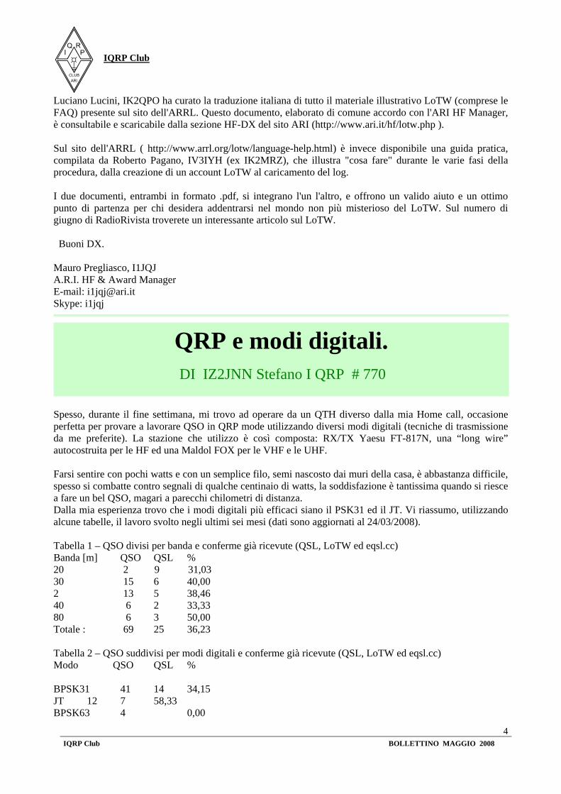
Spesso, durante il fine settimana, mi trovo ad operare da un QTH diverso dalla mia Home call, occasione perfetta per provare a lavorare QSO in QRP mode utilizzando diversi modi digitali (tecniche di trasmissione da me preferite). La stazione che utilizzo è così composta: RX/TX Yaesu FT-817N, una “long wire” autocostruita per le HF ed una Maldol FOX per le VHF e le UHF. Farsi sentire con pochi watts e con un semplice filo, semi nascosto dai muri della casa, è abbastanza difficile, spesso si combatte contro segnali di qualche centinaio di watts, la soddisfazione è tantissima quando si riesce a fare un bel QSO, magari a parecchi chilometri di distanza. Dalla mia esperienza trovo che i modi digitali più efficaci siano il PSK31 ed il JT. Vi riassumo, utilizzando alcune tabelle, il lavoro svolto negli ultimi sei mesi (dati sono aggiornati al 24/03/2008). Tabella 1 – QSO divisi per banda e conferme già ricevute (QSL, LoTW ed eqsl.cc) Banda [m] QSO QSL % 20 2 9 31,03 30 15 6 40,00 2 13 5 38,46 40 6 2 33,33 80 6 3 50,00 Totale : 69 25 36,23 Tabella 2 – QSO suddivisi per modi digitali e conferme già ricevute (QSL, LoTW ed eqsl.cc) Modo QSO QSL % BPSK31 41 14 34,15 JT 12 7 58,33 BPSK63 4 0,00
QRP e modi digitali.
DI IZ2JNN Stefano I QRP # 770
IQRP Club
IQRP Club BOLLETTINO MAGGIO 2008
5
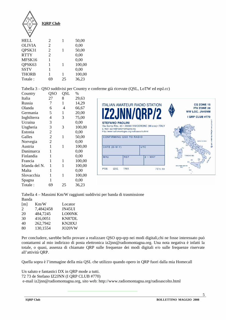
HELL 2 1 50,00 OLIVIA 2 0,00 QPSK31 2 1 50,00 RTTY 2 0,00 MFSK16 1 0,00 QPSK63 1 1 100,00 SSTV 1 0,00 THORB 1 1 100,00 Totale : 69 25 36,23 Tabella 3 – QSO suddivisi per Country e conferme già ricevute (QSL, LoTW ed eqsl.cc) Country QSO QSL % Italia 27 8 29,63 Russia 7 1 14,29 Olanda 6 4 66,67 Germania 5 1 20,00 Inghilterra 4 3 75,00 Ucraina 3 0,00 Ungheria 3 3 100,00 Estonia 2 0,00 Galles 2 1 50,00 Norvegia 2 0,00 Austria 1 1 100,00 Danimarca 1 0,00 Finlandia 1 0,00 Francia 1 1 100,00 Irlanda del N. 1 1 100,00 Malta 1 0,00 Slovacchia 1 1 100,00 Spagna 1 0,00 Totale : 69 25 36,23 Tabella 4 – Massimi Km/W raggiunti suddivisi per banda di trasmissione Banda [m] Km/W Locator 2 7,4842458 JN45UI 20 484,7245 LO00NK 30 416,0051 KN87DL 40 262,7942 KN28XJ 80 130,1554 JO20VW Per concludere, sarebbe bello provare a realizzare QSO qrp-qrp nei modi digitali,chi ne fosse interessato può contattarmi al mio indirizzo di posta elettronica [email protected]. Una nota negativa è infatti la totale, o quasi, assenza di chiamate QRP sulle frequenze dei modi digitali e/o sulle frequenze riservate all’attività QRP. Quella sopra è l’immagine della mia QSL che utilizzo quando opero in QRP fuori dalla mia Homecall Un saluto e fantastici DX in QRP mode a tutti. 72 73 de Stefano IZ2JNN (I QRP CLUB #770) e-mail [email protected], sito web: http://www.radiomontagna.org/radioascolto.html

IQRP Club
IQRP Club BOLLETTINO MAGGIO 2008
6
QRP and digital modes written by Z2JNN Stefano (I QRP CLUB #770), e-mail [email protected], web page: http://www.radiomontagna.org/radioascolto.html Usually, during weekend, I operate in a different place than home call, so I can perfectly match QSO in QRP using different digital modes (my favourite modulations). The station is so organized: RX/TX Yaesu FT-817N, one “long wire” self build for HF and one Maldol FOX for VHF and UHF. Let your signal be heard with so few watts and a simple wire, halfly hidden in the home walls, is hard, usually you fight with hundred watt signals, but the satisfaction to do a nice QSO, better if far, is big. Based on my experience I found that the best digital modes are PSK31 and JT. I summarize, using some tables, the result of work of last six months (data updated to April 24th 2008). Table 1 – QSO separated for band and confirmation already received (QSL, LoTW and eqsl.cc) Table 2 – QSO divided for digital modes and confirmation already received (QSL, LoTW and eqsl.cc) Table 3 – QSO divided by Country and confirmation already received (QSL, LoTW and eqsl.cc) Tabella 4 – Maximum Km/W rreached divided by band transmissin In summary, should be nice try to realize QSO qrp to qrp using digital modes, for who is interested can take contact with me using email [email protected]. A bad note is the almost totally lack of QRP calls on the digitas mode frequencies or QRP frequencies. The picture is my QSL used for calls out of my Home Greeting to all and good DX using QRP. 72 73 de Stefano IZ2JNN (I QRP CLUB #770)

IQRP Club
IQRP Club BOLLETTINO MAGGIO 2008
7
E' dal 17 marzo dell'anno 2000, da quando terminato il montaggio e il mio K2 ha dato i primi segni di vita, che il SOLE lo alimenta. Il sole l'alimenta sia nella postazione fissa, sia quando con me va errabondo su i monti, per il Sota. In questi sette anni il K2 è stato aggiornato internamente puntualmente, ha avuto la sua prima batteria nuova al Ni-MH poi, come si conviene,al Litio, ma la sua alimentazione è stata sempre e solamente dal sole. Ho fatto a tutto oggi 38.725 qso in tutti i modi, partecipando a contest internazionali fra i più importanti al mondo e raggiungendo qualche volta piazzamenti prestigiosi. Ho scritto da qualche parte le antenne che uso, le fatiche che faccio per mantenere questi livelli nelle prestazioni, ma non ho detto, o ho detto poco, quanto devo al sole e al mio K2. Dunque, si può, oggi, in qrp, e segnamente in qrp, senza arroganza, in modo onesto e veritiero raggiungere grandi obbiettivi o anche più semplicemente parlare con un amico lontano, o inseguire un dx quasi ad essere "qro" senza accorgersi di usare mezzi antichi e semplici come il sole. Allora, l'antico sole, opportunamente coniugato a un mezzo moderno come il K2, e malgrado che questo operatore stia ancora a giostrare in modo antico con la telegrafia, si può parlare direttamente con il mondo, senza satelliti, con "briciole" di RF, prodigiosamente annullando, una volta di più, le distanze e ancora meravigliando. Questa è la poesia del qrp, riuscire ancora a costruire qualcosa con le proprie mani, che ti permetta di spaziare nell'etere, raggiungere l'infinito ...quasi a confondere,a far sembrare i miracoli ancor oggi possibili. Nelle foto si evidenziano i segni per indicare questa attività, anche se nulla vien detto della passione e della fatica, che non sono dimenticate, ma che ci sono, presenti ed essenziali, come il sole. 1) II pannello solare: Dimensioni 270x300x8 mm.12,8V 800mA (media esposizione al sole). Peso 630 gr 2) Il carica batteria: Per batterie Litium 3 celle 7,4V 11,1V imput DC 12-15V Output 7.50 mA. Peso 44 gr. 3) La batteria: Due, in parallelo da 3 celle Li-ion/Li-Po da 9 Ah. Dimensioni 145x45x35 mm. Peso 630 gr. 4) Il ricetrans: Elecraft K2,sempre aggiornato sino al DSP, con modifiche interne:Batteria al Litio 4 Ah. Presa commutata per pannello solare, BT interna-esterna.Presa per segnali digitali, presa per key verticale, bnc per Antenna 160m. Filtri per segnali digitali. Modifica BF uscita altoparlante. I1BAY... con il sole, I Qrp #309
"Q"uelle "R"adio "P"iccole" e il sole
DI I1BAY IQRP # 309

IQRP Club
IQRP Club BOLLETTINO MAGGIO 2008
8
That Small Radios and the sun
Since March 17th 2000 my K2 is alive and kicking while the SUN is supplying it. Sun supply K2 even in base station than for Sota in mountain excursion. In those 7 years my K2 was improved with new Ni-MH batteries, afterwards with Lithium batteries but the source was always the sun. Up to now I did 38'725 QSOs in all modes, taking part to most important international contests and reaching nice positions. I've written somewhere about antennas that I use, efforts used for keep high performance, but I've never thanks the sun and K2 for their jobs. So today is possible, using QRP, without arrogance or tricks, reach great goals or communicate with far friend or at least tracking a DX without thinking that we are using sun as supply. Thus, the old sun joined with a modern device like K2, it is possible to connect the world using telegraphy and so little RF, without satellites, canceling and amazing, once more, distances and ourself. This is QRP's poesy, reach to build something that deals with void using your hands…reaching infinite….miracle is still possible. In the photos you can see signs of this activity, but passion and fatigue cannot be felt thru photos but they were like the sun! 1) Solar panel: 10.6''x11.8''x0.3'' 12.8V 800mA (average sun). Weigth 22oz 2) Battery charger: lithium one: 3 cells 7.4V 11.1V input DC 12-15V Output 7.5 mA. Weight 1.5oz 3) Battery: two in parallel, 3 Li-ion/PoLi cell each of 9Ah. Dimensions: 5.7''x1.7''x1.3'' Weigth 22.2 oz 4) The rig: Elecraft K2, always upgraded to DSP with following mods: � Lithium battery 4Ah � Outlet for solar panel, BT in-out � Outlet for digital signals � Outlet for vertical key � BNC outlet for 160m Antenna � Digital signal filters � BF output changed for speaker I1BAY... with sun, I Qrp #309
L'ho prenotato e atteso per quasi otto mesi poi l'altro giorno è arrivato il K3 qrp. Invece di arrivarmi un ricetrans, mi è arrivato un computer camuffato da radio con licenza per trasmettere. Ho messo qualche tempo per farlo funzionare e ancora di più per capire come funziona visto la complessità del "mostro", ho capito invece subito che era finita un'epoca, quella in cui "ti facevi la radio". La mia generazione targata 900 o "un millennio fai.... dunque, oggi rimane estromessa dalla genesi, rito fondante praticato per più di sessant'anni e che risultava ancora possibile fino a poco fa e proprio nel qrp, ultimo baluardo del fai da te! Si dice il progresso ! Come fai ad amare questi mostri, io che ho sempre creduto che quando tocchi un tasto fai una funzione di on-off, e invece ora debbo imparare che se lo palpo faccio una funzione, se lo pigio un'altra, se lo sfioro un'altra ancora e via così ! E poi il soft ? cosa è in una radio? Cosa vuoi dire la confusione che lo trasmetto in cw e dal "mostro può uscire rtty ? Cosa vuoi dire che , il "mostro riceve e scrive il cw sul display, demodula e fa la rtty trasmettendo con un tasto e l'operatore che fa in sto casino, come fa a tenere a mente tutto? Bisogna girare con la "Bibbia in tasca.
QRP Elecraft K3, una nuova era
DI I1BAY I QRP # 309
IQRP Club
IQRP Club BOLLETTINO MAGGIO 2008
9
lo mi deprimo (eufemismo). Non nego che quando "maneggio l'oggetto" ho dei brividi per quello che può fare, per quello che riesco a fare, però è come essere in compagnia di una donna leggiadra che devi trattare con estrema attenzione, che devi solo sfiorare che se fai un gesto inconsulto ti lascia. E’ la fine della conoscenza intima, del sapere come è fatta, cosa c'è dentro e come reagirà nell'uso, 1' amica radio. Certamente è la nuova frontiera, è cioè, cosa attende le nuove generazioni, io per il momento so cosa perdo, e non è cosa da poco a cominciare dalla tranquillità. Ma via, affinché il mio "mugugno da "antico” serva almeno a mettervi sull'avviso di cosa vi aspetta e magari
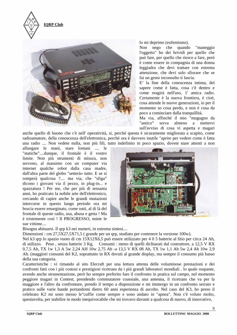
anche quello di buono che c'è nell' operatività, si, perché questa è sicuramente migliorata a scapito, come radioamatore, della conoscenza dell'elettronica, perché ora è davvero inutile "aprire per vedere come è fatta una radio .... Non vedete nulla, non più fili, tutto indefinito in poco spazio, dovete stare attenti a non allungare le mani, stare lontani .... le "statiche"....dunque, il frontale è il vostro limite. Non più strumenti di misura, non servono, al massimo con un computer via internet qualche robot dalla casa madre, dall'altra parte del globo "setterà» tutto. E se si romperà qualcosa ?.... ma via, che "sfiga” dicono i giovani via il pezzo, in plug-in... e spazzatura ! Per me, che per più di sessanta anni, ho praticato la nobile arte dell'elettronico, cercando di capire anche le grandi mutazioni intercorse in questo lungo periodo ora mi brucia essere emarginato, come tutti, al di là del frontale di queste radio, usa, abusa e getta ! Ma è tristemente così ! Il PROGRESSO, miete le sue vittime.... Bisogna abituarsi. Il qrp k3 nei numeri, in estrema sintesi.... Dimensioni : cm 27,5X27,5X71,5 ( grande per un qrp, studiato per contenere la versione 100w). Nel k3 qrp lo spazio vuoto di cm 15X12X6,5 può essere utilizzato per 4 0 5 batterie al litio per circa 24 Ah, di utilizzo. Peso , senza batterie 3 Kg. Consumi : meno di quelli dichiarati dal costruttore, a 12,5 V RX 0,7,5 Ah, TX 1w 1,3 A 5w 2,24 AH 10w 2,75 Ah -a 13,5 V RX 08 Ah, TX 1w 1,1 Ah 5w 2,4 Ah 10w 2,9 Ah. (maggiori consumi del K2, soprattutto in RX dovuti al grande display, ma sempre il consumo più basso della sua categoria. Caratteristiche : vi rimando al sito Elecraft per una lettura attenta delle voluminose prestazioni e dei confronti fatti con i più costosi e prestigiosi ricetrans da i più grandi laboratori mondiali . lo quale ruspante, avendo anche strumentazione, però ho sempre preferito fare il confronto in pratica sul campo, nel momento peggiore magari in Contest, prendendo commutatore coassiale, una antenna, il ricetrans che va per la maggiore e l'altro da confrontare, prendo il tempo a disposizione e mi immergo in un confronto serrato e pratico sulle varie bande portandomi dietro 60 anni esperienza di ascolto. Nel caso del K3, ho preso il celebrato K2 mi sono messo le"cuffie come sempre e sono andato in "apnea". Non c'è voluto molto, questavolta, per stabilire in modo inequivocabile che mi trovavo davanti a qualcosa di nuovo, di innovativo,
IQRP Club
IQRP Club BOLLETTINO MAGGIO 2008
10
un salto, o l'inizio di una nuova era, dove il termine radio diventa quasi desueto dalle mie parti, i vecchi saggi, quando vogliono significare una grande differenza dicono .... "Questi sono fichi di un altro cavagno! " Ebbene questa volta credo,si possa dire,che non è cambiato solo il cavagno, ma anche l'albero Veniamo alle dolenti note :Cosa viene a costare il "salto ...la nuova era... ecc,ecc" Come qrp, non poco .... 1600 $ il k3 10w assemblato, nudo, poi ci vuole 1'ATU, 289 $, è meglio mettere due filtri 8 poli nel Rx main 250$+39 $ di trasporto,il bus adattatore 39$,la spedizione UPS 185$, poi la dogana in euro 279. Amen ...così, semplicemente, con un ricevitore e in qrp Insomma, oggi sembra che fare qrp sia diventato un lusso e si risparmi, in fondo, solo la RF! L'unica consolazione, si può dire, è avere un qrp DOC, che,volendo,con qualche aggiunta può diventare uno straordinario ricetrans qro, e non è poco ! 72' de 11 BAY, 1 qrp # 309
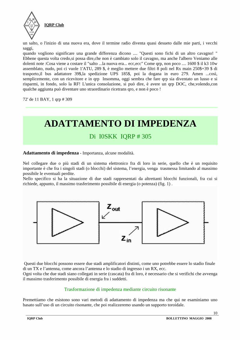
Adattamento di impedenza - Importanza, alcune modalità. Nel collegare due o più stadi di un sistema elettronico fra di loro in serie, quello che è un requisito importante è che fra i singoli stadi (o blocchi) del sistema, l’energia, venga trasmessa limitando al massimo possibile le eventuali perdite. Nello specifico si ha la situazione di due stadi rappresentati da altrettanti blocchi funzionali, fra cui si richiede, appunto, il massimo trasferimento possibile di energia (o potenza) (fig. 1) .
Questi due blocchi possono essere due stadi amplificatori distinti, come uno potrebbe essere lo stadio finale di un TX e l’antenna, come ancora l’antenna e lo stadio di ingresso i un RX, ecc. Ogni volta che due stadi siano collegati in serie (cascata) fra di loro, è necessario che si verifichi che avvenga il massimo trasferimento possibile di energia fra i suddetti.
Trasformazione di impedenza mediante circuito risonante Premettiamo che esistono sono vari metodi di adattamento di impedenza ma che qui ne esaminiamo uno basato sull’uso di un circuito risonante, che poi realizzeremo usando un supporto toroidale.
ADATTAMENTO DI IMPEDENZA
Di I0SKK IQRP # 305

IQRP Club
IQRP Club BOLLETTINO MAGGIO 2008
11
Una coppia di induttanze accoppiate (fig. 2) ed eventualmente con un nucleo di materiale ferromagnetico su cui sono avvolte, realizzano un trasformatore. Ricordiamo che l’effetto di trasformazione avviene solo in regime di corrente alternata. L’induttanza L1 viene detta avvolgimento primario, la L2 avvolgimento secondario. Come sappiamo la relazione elettrica che sussiste fra tensione V e corrente I negli avvolgimenti (primario e secondario) dipende dal rapporto fra le spire nei medesimi avvolgimenti. Quello che avviene nel trasformatore, riguardo l’impedenza è l’effetto che si riporta sul primario, per il carico RL
che è collegato ai morsetti del secondario: Riferendoci alla figura 3 è il rapporto fra N2 ed N1, dove N2 è il numero di spire di L2 ed N1 quello di L1.
Si ha cioè: 2
1
NNN
= ( 3 )
Quindi sul primario noi vedremo l’effetto di RL sul secondario, come se ci fosse una resistenza RLeq di valore pari a:
2L
LeqRRN
= ( 4 )
Facciamo un esempio: supponiamo che L1 abbia 10 spire e che L2 ne abbia 30, e che RL = 2700 Ω; si ha che N =30 /10 = 3. Perciò ai morsetti del primario troveremo lo stesso effetto di una RLeq = (2700 /33) = 300 Ω __________ L’effetto sopra descritto può essere sfruttato per far funzionare il circuito LC sia da filtro sia da adattattore di impedenza, nello stesso tempo; nel caso bisogna tenere in conto di varie cose: - il circuito composto dalla serie di L2A ed L2B è equivalente alla L totale del circuito risonante e pertanto il valore della somma delle due induttanze va messo nella formula [4], si ha cioè (L = L2A + L2B ); - il carico che noi simbolizziamo con RL, può essere ad esempio un filtro, o meglio la sua impedenza d’ingresso (supponendo essa sia di valore solamente resistivo e non presenti, quindi, reattanze; in caso contrario al posto di una RL, useremo una impedenza, cioè una ZL , ma i concetti rimangono invariati); - possiamo usare come trasformatore una coppia di induttanze accoppiate, normalmente, ovvero un circuito del tipo di fig. 4;

IQRP Club
IQRP Club BOLLETTINO MAGGIO 2008
12
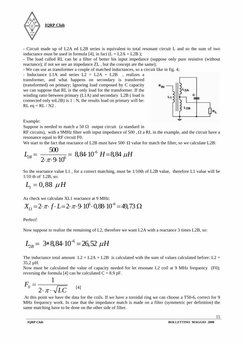
- l’induttanza L1A e la serie L2 = L2A + L2B , realizzano un trasformatore, e come tale quello che accade al secondario, si ripropone al primario, debitamente trasformato; trascurando il carico composto dalla capacità C, possiamo supporre che per il trasformatore che ora consideriamo, sia RL l’unico carico. Se il rapporto fra spire del primario (L1A) e spire del secondario L2B ( visto che il carico è collegato solo ad L2B) è di 1 : N, l’effetto sul primario del carico RL collegato al secondario, sarà una resistenza RL eq = RL / N2 . Facciamo un esempio numerico:
supponiamo si debba adattare ad un circuito la cui impedenza di uscita è di 50Ω (come abbiamo già detto, una sorta di standard nei circuiti RF), l’impedenza d’ingresso di un filtro a 9 MHz da 500 Ω, che nell’esempio rappresenta RL, e che il circuito debba risuonare appunto alla frequenza F0 del filtro. Partiamo dal fatto che la reattanza di L2B deve presentare il valore di 500 Ω per adattarsi al filtro, per cui ricaviamo quanto deve valere L2B:
6
2 6
500 8,84 10 8,842 9 10BL H Hμπ
−= = ⋅ =⋅ ⋅ ⋅
Di conseguenza il valore della reattanza di L1 deve essere 1/10 del valore di quella di L2B, per poter presentare il rapporto corretto che fornisce l’adattamento, quindi avremo che anche il valore di L1, sarà 1/10 di quello di L2B, cioè:
1 0,88L Hμ= Come riprova calcoliamo il valore di reattanza XL1 alla frequenza di 9 MHz:
6 61 2 2 9 10 0,88 10 49,73LX f Lπ π −= ⋅ ⋅ ⋅ = ⋅ ⋅ ⋅ ⋅ ⋅ = Ω
Come desiderato. Ora supponiamo di realizzare la rimanente parte di L2, quindi L2A facendo sì che la sua reattanza sia almeno 3 volte pari a quella di L2B, quindi si deve avere che:
62 3 8,84 10 26,52BL Hμ−= ∗ ⋅ =
Il valore complessivo dell’induttanza L2 = L2A + L2B si ricava sommando i due valori ora calcolati, e si ottiene L2 = 35,2 µH.

IQRP Club
IQRP Club BOLLETTINO MAGGIO 2008
13
Ora si deve calcolare il valore della capacità necessaria a far risuonare la bobina L2 sulla frequenza (F0) dei 9 MHz.; invertendo la formula seguente [4] si ricava C = 8.9 pF.
01
2F
LCπ=
⋅ ⋅
[4] A questo punto abbiamo i dati per realizzare la bobina: ipotizzando di usare un supporto toroidale: possiamo scegliere di usare un T50-6 che è adatto alla frequenza dei 9 MHz. Nel caso questo sia appunto l’adattatore di impedenza di un filtro che è un dispositivo simmetrico, la medesima cosa va fatta all’altro lato del suddetto filtro. Progettazione di un trasformatore a RF a larga banda Normalmente, è buon uso progettuale, far sì che la reattanza del primario del trasformatore a larga banda sia pari a 5 volte il valore dell’impedenza del primario. Quindi, ad esempio, dovendo realizzare un trasformatore che faccia passare da 200 Ω a 50 Ω, al primario dovremo avere una impedenza pari a 1000 Ω alla più bassa frequenza di utilizzo di detto trasformatore ( possiamo supporre che questa sia quella degli 1,8 MHz). Riferiamoci alla figura 5. Per questo esempio avremo bisogno di usare un trasformatore in avvolgimento bifilare che abbia una impedenza di 1000 Ω alla frequenza di 1,8 MHz, il che vuol dire una induttanza di 88 μH; esaminando il datasheet della Amidon possiamo vedere che il nucleo di ferrite del tipo FT 50-61 può fornire una induttanza di AL = 68 mH/ 1000 spire: dato che a noi serve una induttanza di 0,088 mH (equivalenti appunto a 88 μH), usando la formula fornita sul catalogo Amidon:
( )1000
( /1000 )desiderata
spireL
L mHNA mH spire
= ⋅
[5] Il risultato sarà che con 36 spire su questo tipo di supporto, avremo il valore richiesto di induttanza. Impedance matching Impedance matching – Importance, some guidelines. The important requirement connecting two or more electronic system stages in series is that energy between stages (or blocks) must flow without loss.

IQRP Club
IQRP Club BOLLETTINO MAGGIO 2008
14
In brief this is the main purpose: transmit energy between functional blocks without or at least with little energy (power) loss (fig. 1). Those blocks can be two distinct amplifier stages, can be a power amplifier and an antenna, can be an antenna and an input stage and so on. Every time that two stages are connected (chained) is necessary that we have maximum energy transfer. The energy transfer is maximized tuning the impedance of two stages: this
task is called “Impedance Matching”.
Impedance transformation using resonance circuit Many impedance matching methods exists, but here we write about one that uses a resonance circuit, realized with a toroidal support.
A couple of matched inductance (fig. 2) and perhaps wrapped on a ferromagnetic core realizes a transformator. Remember that transformer works only with AC current. Inductance L1 is called primary winding, L2 is called secondary winding. As we know the electrical relation between current I and tension V in windings depends on turns number of windings. Talking of impedance the load RL connected to secondary is seen in a different way on the primary winding: Looking figure 3 is the ratio between N2 and N1, where N2 is the number of windings of L2 and N1 is the number of windings of L1.
And so: 2
1
NNN
= ( 3 )
At last on primary we see a load based on RL called RLeq with value:
2L
LeqRRN
= [4]
Example: suppose that L1 has 10 wraps and L2 has 30 and load RL = 2700 Ω; we calculate N =30 /10 = 3. So on primary winding clamps we should have a load with an electrical behavior as RLeq = (2700 /33) = 300 Ω __________ The effect described above can be used in a LC circuit for having both filter and impedance matching in the same circuit; in that case some things have to keep in mind:
IQRP Club
IQRP Club BOLLETTINO MAGGIO 2008
15
- Circuit made up of L2A ed L2B series is equivalent to total resonant circuit L and so the sum of two inductance must be used in formula [4], in fact (L = L2A + L2B ); - The load called RL can be a filter of better his input impedance (suppose only pure resistive (without reactance); if not we see an impedance ZL , but the concept are the same); - We can use as transformer a couple of matched inductances, so a circuit like in fig. 4; - Inductance L1A and series L2 = L2A + L2B , realizes a transformer, and what happens on secondary is transferred (transformed) on primary; Ignoring load composed by C capacity we can suppose that RL is the only load for the transformer. If the winding ratio between primary (L1A) and secondary L2B ( load is connected only toL2B) is 1 : N, the results load on primary will be: RL eq = RL / N2 . Example: Suppose is needed to match a 50 Ω output circuit (a standard in RF circuits), with a 9MHz filter with input impedance of 500 , Ω a RL in the example, and the circuit have a resonance equal to RF circuit F0. We start to the fact that reactance of L2B must have 500 Ω value for match the filter, so we calculate L2B:
62 6
500 8,84 10 8,842 9 10BL H Hμπ
−= = ⋅ =⋅ ⋅ ⋅
So the reactance value L1 , for a correct matching, must be 1/10th of L2B value, therefore L1 value will be 1/10 th of L2B, so:
1 0,88L Hμ= As check we calculate XL1 reactance at 9 MHz:
6 61 2 2 9 10 0,88 10 49,73LX f Lπ π −= ⋅ ⋅ ⋅ = ⋅ ⋅ ⋅ ⋅ ⋅ = Ω
Perfect! Now suppose to realize the remaining of L2, therefore we want L2A with a reactance 3 times L2B, so:
6
2 3 8,84 10 26,52BL Hμ−= ∗ ⋅ = The inductance total amount L2 = L2A + L2B is calculated with the sum of values calculated before: L2 = 35,2 µH. Now must be calculated the value of capacity needed for let resonate L2 coil at 9 MHz frequency (F0); reversing the formula [4] can be calculated C = 8.9 pF.
01
2F
LCπ=
⋅ ⋅ [4]
At this point we have the data for the coils. If we have a toroidal ring we can choose a T50-6, correct for 9 MHz frequency work. In case that the impedance match is made on a filter (symmetric per definition) the same matching have to be done on the other side of filter.

IQRP Club
IQRP Club BOLLETTINO MAGGIO 2008
16
Design of a wide band RF transformer Usually, for a good design, reactance of primary must be five time impedance of primary. So if we need a transformer from 200 Ω to 50 Ω, on the primary we need an impedance of at least 1000 Ω for the lowest frequency use of the designed transformer (suppose lower frequency is 1,8 MHz). Refer to figure 5.
For this example we need a transformer with bifilar winding with impedance of 1000 Ω at 1,8 MHz, this means an inductance of 88 μH; reading the Amidon datasheet we found that FT 50-61 ferrite can give an inductance AL = 68 mH/ 1000 coils: we need an inductance of 0,088 mH (equivalent to 88 μH), using the formula given by Amidon datasheet:
( )1000( /1000 )
desiderataspire
L
L mHNA mH spire
= ⋅ [5]
The result will be 36 coils on this ferrite and we'll have the desired inductance value.
A multi-band wire antenna that performs exceptionally well even though it confounds antenna modeling software The design of the Mystery antenna was inspired by an article written by James E. Taylor, W2OZH, in which he described a low profile collinear coaxial array. This antenna covers 80 to 6 meters with low feed point impedance and will work with most radios, with or without an antenna tuner. It is approximately 100 feet long, can handle the legal limit, and is easy and inexpensive to build. It’s similar to a G5RV but a much better performer especially on 20 meters. The W5GI Mystery antenna, erected at various heights and configurations, is currently being used by thousands of amateurs throughout the world. Feedback from users indicates that the antenna has met or exceeded all performance criteria. The “mystery” part of the antenna comes from the fact that it is difficult, if not impossible, to model and explain why the antenna works as well as it does. The antenna is especially well suited to hams who are unable to erect towers and rotating arrays. All that's needed is two vertical supports (trees work well) about 130 feet apart to permit installation of wire antennas at about 25 feet above ground. The W5GI Multi-band Mystery Antenna is a fundamentally a collinear antenna comprising three half waves in-phase on 20 meters with a half-wave 20 meter line transformer. It may sound and look like a G5RV but it
The W5GI Multi-band Mystery Antenna
Inviato da I0SKK IQRP # 305

IQRP Club
IQRP Club BOLLETTINO MAGGIO 2008
17
is a substantially different antenna on 20 meters. Louis Varney’s antenna, although three half waves long, was an out-of-phase aerial. Mr. Varney had two specific reasons for selecting a 3 half waves on 20... he wanted a four-lobe radiation pattern, at least unity gain and a low feed point impedance. The Mystery antenna, on the other hand, presents a six-lobe pattern on 20 meters, gain broadside to the antenna, and also low feed point impedance to simplify matching the antenna to the rig. Additionally, the Mystery antenna is designed to work at least as well, on the other HF bands as a G5RV. In short, the Mystery antenna is a sky wire that incorporates the advantages of a 3 element collinear and the G5RV antenna. In its standard configuration, a collinear antenna uses phase reversing stubs added at the ends of a center fed dipole. These stubs put the instantaneous RF current in the end elements in phase with that in the center element. You can make these phase reversing stubs from open wire line or coaxial cable. Normally, a shorted quarter-wave stub is used, but an open-ended half wave stub would also work. The problem is that the dangling stubs are unwieldy and or unsightly. An article written by James E. Taylor, “COCOA-A Collinear Coaxial Array,” published in 73 Amateur Radio, August 1989, describes a low profile collinear coaxial array. According to Taylor, when you apply a RF voltage to the center conductor at the open end, the stub causes a voltage phase lag of 180 degrees at the adjacent coax shield. This happens because the RF is delayed by one quarter-cycle as it passes from left to right, inside the coax to the shorted (opposite) end. There’s another quarter-cycle delay as the wave passes back from right to left inside the coax and emerges on the shield at the open end. Add up the delays and you get a total time delay of one-half cycle, or 180 degrees. In essence, the coax section serves two purposes: it provides the necessary delay and provides part of the radiating element in a collinear array. The first prototypes of the Mystery antenna used the Taylor formulas, which which called for cutting the wires to a quarter wave length using the formula 234/f(Mhz) and the coax, using the same formula, but applying an appropriate velocity factor. The first version of my antenna worked well on 20 meters but failed as a multi-band antenna. The second antenna was built with constructed with the coax cut to the same length as the wire. This was done with the belief that perhaps the coax didn’t behave like coax and therefore the velocity factor wasn’t applicable. Surprisingly, the new antenna performed exceptionally well on 20 meters, had low SWR and performed just as well on the other HF bands and 6 meters as my G5RV reference antenna. Step-by-Step Construction The W5GI Multi-band Mystery Antenna looks like a plain dipole (see figure1 and photo A) and is very simple to build.
Builders of the Mystery antenna will need the following materials: � 3 wish bone insulators � About 70 feet of wire (14 gauge household electrical wire works well,) � Sufficient twin lead or open wire to make a half wave section on 20 meters. Window-type 18 gauge 300 ohm ribbon works best. The Wireman is an excellent source for antenna wire and 300 ohm line. � 34 feet of RG8X mini-coax � An electrical connector, available from most electrical parts stores, to
connect the twin lead and coax � Shrink tubing to cover the exposed coax joints

IQRP Club
IQRP Club BOLLETTINO MAGGIO 2008
18
The antenna can be built in less than an hour when you have the above materials. When you’re ready to proceed, perform the following steps: 1. Cut the electrical wire into four equal lengths of 17 feet. 2. Cut the two lengths of coax to 16’6” each. 3. Cut a 20 meter half-wave section of twin lead. This piece needs to be adjusted by its velocity factor. If 300 ohm window type line is used with a VF of .91, the total length will be 30 ft. Alternatively, 450 ohm, solid 300 ohm or homemade open-wire line can be used provided the
electrical length is on-half wave on 20 meters. Actual length will vary, typically between 27 and 35 ft., depending on type and velocity factor. 4. Trim two inches of braid from one end of both lengths of coax (Item A). 5. Trim one inch of braid and center insulator from the opposite end of both coax sections (Item B). 6. Build a 20-meter dipole without end insulators. Note: The next two steps 7 and 8 of the construction process involve connecting only the "inner" end section of the coax section to one end of the dipole; the shield is not connected to anything here. At the other end of the coax section both the coax shield and second wire section are connected to the coax center conductor. 7. Connect one end of the dipole to the center conductor of the coax (Item A) and cover with shrink tubing as shown in photo B below. 8. Connect the opposite end of the coax (Item B) to braid AND quarter wave wire section, cover with shrink tubing, and connect to end insulator as shown in Photo C below.
9. Install the twin lead through the holes of the center insulator (you may have to enlarge the holes) and solder to antenna wire as shown in photo D below. 10. Connect the opposite side of the twin lead to the coax as shown in photo E below. Almost any type of connection will work provided the connection is stable and sealed properly. 11. Install the antenna with the center conductor at least 25 feet high. Mine is installed in a horizontal plane; however, others have installed the ‘GI antenna as an inverted-vee and are getting excellent results.
IQRP Club
IQRP Club BOLLETTINO MAGGIO 2008
19
On-the-Air Performance
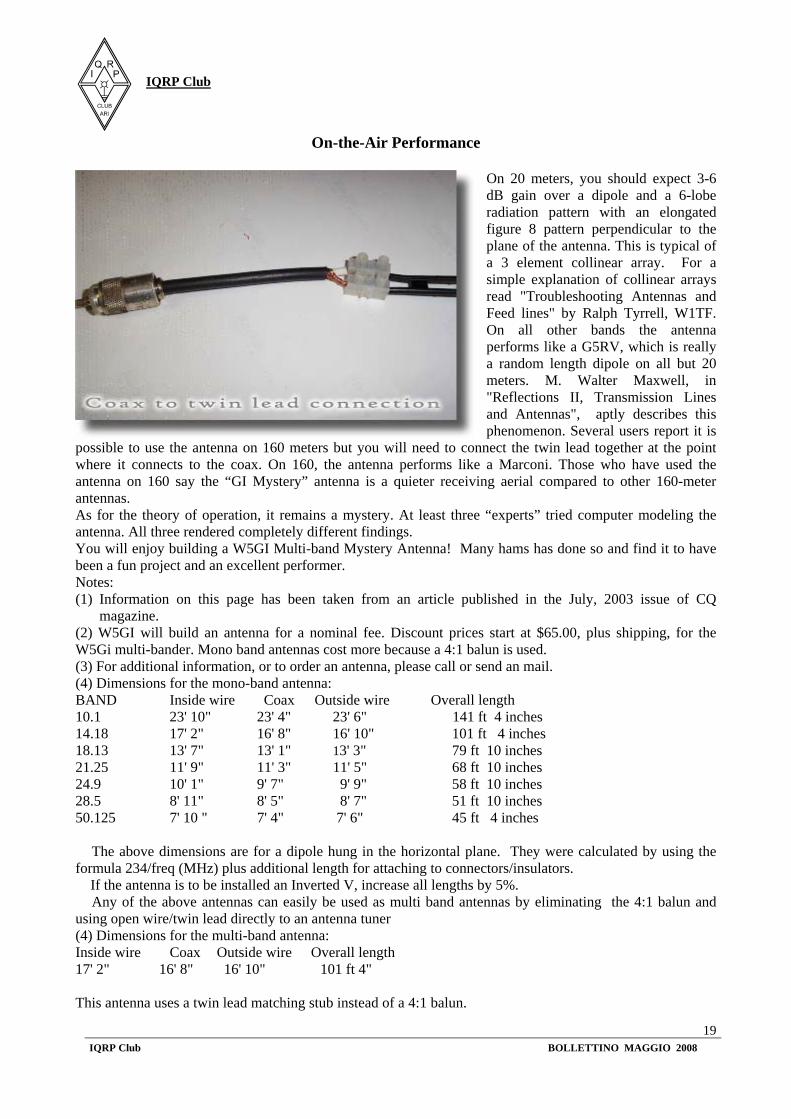
On 20 meters, you should expect 3-6 dB gain over a dipole and a 6-lobe radiation pattern with an elongated figure 8 pattern perpendicular to the plane of the antenna. This is typical of a 3 element collinear array. For a simple explanation of collinear arrays read "Troubleshooting Antennas and Feed lines" by Ralph Tyrrell, W1TF. On all other bands the antenna performs like a G5RV, which is really a random length dipole on all but 20 meters. M. Walter Maxwell, in "Reflections II, Transmission Lines and Antennas", aptly describes this phenomenon. Several users report it is
possible to use the antenna on 160 meters but you will need to connect the twin lead together at the point where it connects to the coax. On 160, the antenna performs like a Marconi. Those who have used the antenna on 160 say the “GI Mystery” antenna is a quieter receiving aerial compared to other 160-meter antennas. As for the theory of operation, it remains a mystery. At least three “experts” tried computer modeling the antenna. All three rendered completely different findings. You will enjoy building a W5GI Multi-band Mystery Antenna! Many hams has done so and find it to have been a fun project and an excellent performer. Notes: (1) Information on this page has been taken from an article published in the July, 2003 issue of CQ
magazine. (2) W5GI will build an antenna for a nominal fee. Discount prices start at $65.00, plus shipping, for the W5Gi multi-bander. Mono band antennas cost more because a 4:1 balun is used. (3) For additional information, or to order an antenna, please call or send an mail. (4) Dimensions for the mono-band antenna: BAND Inside wire Coax Outside wire Overall length 10.1 23' 10" 23' 4" 23' 6" 141 ft 4 inches 14.18 17' 2" 16' 8" 16' 10" 101 ft 4 inches 18.13 13' 7" 13' 1" 13' 3" 79 ft 10 inches 21.25 11' 9" 11' 3" 11' 5" 68 ft 10 inches 24.9 10' 1" 9' 7" 9' 9" 58 ft 10 inches 28.5 8' 11" 8' 5" 8' 7" 51 ft 10 inches 50.125 7' 10 " 7' 4" 7' 6" 45 ft 4 inches � The above dimensions are for a dipole hung in the horizontal plane. They were calculated by using the formula 234/freq (MHz) plus additional length for attaching to connectors/insulators. � If the antenna is to be installed an Inverted V, increase all lengths by 5%. � Any of the above antennas can easily be used as multi band antennas by eliminating the 4:1 balun and using open wire/twin lead directly to an antenna tuner (4) Dimensions for the multi-band antenna: Inside wire Coax Outside wire Overall length 17' 2" 16' 8" 16' 10" 101 ft 4" This antenna uses a twin lead matching stub instead of a 4:1 balun.
IQRP Club
IQRP Club BOLLETTINO MAGGIO 2008
20
� Use only 300 ribbon line for the matching stub. Start with 34 ft 7", trim as necessary to obtain lowest SWR. � Mono-banders with either a voltage or current (preferred) 4:1 balun. � This antenna exhibit significant gain only on 20 meters. On all other bands the antenna performs like a G5RV.
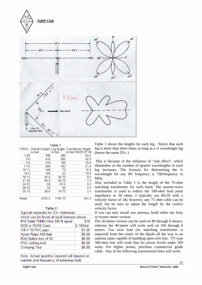
For over forty years, I have been an avid Field Day (FD) participant with clubs both small and large, from coast to coast. During these experiences I observed that top performing FD stations have one thing in common - superior antennas - typically large wire antennas and/or beams. Additionally, I’ve observed that aerials, which required use of antenna tuners for frequency excursions, often confound the inexperienced operator resulting in sub-optimal performance, or even damage to equipment. This article describes versatile broadband wire antennas. These antennas will double your effective radiated power over a dipole, will be easy and inexpensive to build and install, and will be simple to match. They can be operated as traditional dipoles or V-beams. Through careful choice of leg length and use of a matching unit, they can also be used on multiple bands. Because they are broad banded, newcomers to the hobby normally need not worry about antenna tuner adjustments. Perhaps most importantly, they’re fun to build and provide insight into antenna theory that you won’t get from working with dipoles alone. Many hams use half-wave dipoles because of their simplicity and outstanding performance. Increasing the length of each leg has long been advocated as one means of increasing gain. The most popular of the extended length antennas is Louis Varney’s, G5RV configured for 20 meters. The G5RV antenna on 20 meters is over three times as long-tree half wave lengths as a ordinary dipole with a feed point impedance of about 100 ohms. Although Varney initially set out to build a 20-meter antenna, he found that, with some minor changes, the antenna could be used on several other bands. A longer antenna offers significant advantages over a dipole for both portable and permanent installations. These advantages are: ·Gain of 3.4 db over a dipole ·Low feed point impedance; easy to match ·Relatively broad-banded ·Six-lobe (omni-directional) radiation pattern ·Performs well at any height ·Easy to adjust ·Can be configured as a V-beam The remainder of this article will show how to design and build three-half wave antennas for any band 160 to 6 meters. Figure 1 below shows the basic design of a three-half wave antenna with matching transformer.
D3+ High Performance Antennas for Field Day No Mystery Here!
By John P. Basilotto, W5GI
IQRP Club
IQRP Club BOLLETTINO MAGGIO 2008
21
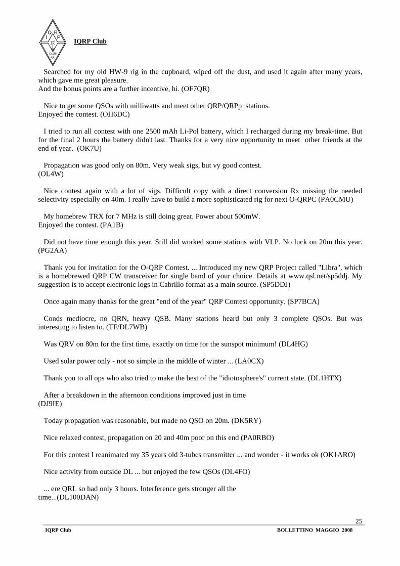
Table 1 shows the lengths for each leg. Notice that each leg is more than three times as long as a ¼ wavelength leg (hence the name D3+.) This is because of the influence of “end effect”, which diminishes as the number of quarter wavelengths in each leg increases. The formula for determining the ¾ wavelength for any HF frequency is 738/frequency in MHz. Also included in Table 1 is the length of the 75-ohm matching transformer for each band. The quarter-wave transformer is used to reduce the 100-ohm feed point impedance to 50 ohms. I typically use RG59 with a velocity factor of .66; however, any 75 ohm cable can be used, but be sure to adjust the length by the correct velocity factor. If you can only install one antenna, build either the forty or twenty meter version. The 20-meter version can be used on 80 through 6 meters, whereas the 40-meter will work well on 160 through 6 meters. Use twin lead (no matching transformer is required) from the center of the dipole all the way to an antenna tuner capable of handling open wire line. TV type 300-ohm line will work fine for power levels under 500 watts. For higher power, purchase commercial grade cable. Any of the following transmission lines will work:

IQRP Club
IQRP Club BOLLETTINO MAGGIO 2008
22
300-ohm window or solid dialectic [works best], 450 ohm line, or consider constructing your own line. All of the materials needed to construct the antennas presented can be purchased at most local home and building hardware stores. Figure 2 shows the method I used to connect the matching transformer to the center insulator. Figure 3 shows the method used to connect to the end insulators.
The D3+ antennas should be installed as high as possible. However, for field day use, I recommend you construct a system which allows the antenna to be lowered or raised. Antennas low to the ground will produce a high angle of radiation, which will improve the receive and transmit signal within 500 miles. For distant communications raise the antenna just before sunset to decrease the angle of radiation. Return the antenna to its lower height just after sunrise to improve close-in performance. The antenna may also be oriented as a horizontal V-beam, if directivity is desired. Furthermore, the V-beam can also be installed with its ends sloped to the ground. The later arrangement, allows the D3+ to be easily moved to change signal direction. These installation suggestions will maximize the antenna’s performance resulting in more contacts. And, you’ll rack up the points. If you can only place the antenna one way, install it as an Inverted-V as high as possible. Tuning the D3+ is simple. Leave a small length of wire at each end-see Figure 3; bend the wire 90 degrees (this is why I recommend solid wire). Use an SWR meter or similar device (an MFJ Antenna Analyzer works great for this step) to determine whether the antenna length needs to be decreased or increased. If the antenna needs to be electrically lengthened, just un-wrap the wire on each leg and move each end insulator, the same distance, away from the center. If it needs to be shortened, cut an equal length (a couple of inches at a time) from each leg. I have found that on 40 meters and higher the SWR is relatively flat across the entire band. On 80/75 and 160 meters the antenna has a much broader bandwidth than a standard dipole. Although this article focused on antennas for Field Day use, the D3+ Antennas make great base antennas as well. Have fun and good luck.

IQRP Club
IQRP Club BOLLETTINO MAGGIO 2008
23
QRP-CONTEST-COMMUNITY (qrpcc) 26-Mar-2008 c/o Dr. Hartmut Weber Schlesierweg 13 D-38228 SALZGITTER e-mail: [email protected] web: http://www.qrpcc.de --------------------------------------------------------- Been on the move again .... and fortunate in that the mild weather permitted /p operation from the car. (DF2HL/p) Strictly speaking the OQRP Contest is the only one I enter - even though often only for part-time attendance. (DF2SJ) Friendly contest, no strain. And I reached my goal of at least 50 QSOs. (DF3ZR) ... the first hour dragged along, hardly any QSOs. I drew a 27m long wire just in time for the contest, thus I was QRV on 80m, too. (DH3LK) Nice to hear more VLP stns taking part. (DJ3KK) Days between xmas & New Year's Day were turbulent here and left no time to adjust for the party, and for the moments when the higher bands open at least a little in this "lazy" sun. (DJ7RS) It was fun again despite heavy QRM on 40m. (DK6AJ) I took some time finding contest activity centering around 3560kHz, but after that the fun started. Friendly ops, no hectics. When no-one else was heard on 80m after 0030UTC I left the contest. (DL7BD) ... and I hope one or the other op will welcome a DL100DAN QSL. (DL4BCE/DL100DAN) No conds on 20m, 40m reasonably. The first DLs on 80m were logged after 2000UTC. Used this fine contest to test a sealed lead acid accumulator ... (DL1KAS) Needed to erect an aerial first, was in DL only for a short holiday... (DL1RNN) ... at least the aerial is home-made: 80cm diameter indoor small twin loop ... who says it can't be done? (DL2NA) House full of visitors. Made 15 QSOs while I looked after my grandchildren. (DL2NH) ... was rather tedious this time. Is it my antenna, or was everyone having a rest on the sofa? (DL3MBE)
Voices from the 23rd Original QRP Contest (29/30 Dec 2007)

IQRP Club
IQRP Club BOLLETTINO MAGGIO 2008
24
The contest was again a pleasure. I think conds weren't that bad, especially both late fore- and early afternoon went well. (DL4LBB) Had little time for a contest, a poor aerial, and made only 2 QSOs, but I submit my log just the same. Being part of it is what counts... (DL4VBN) ... had to prick up my ears quite a bit in order to copy those somewhat weaker QRP signals. (DL6AWJ) After a slow start lots of stations were heard. Low-band conds were quite good. Many VLPs came in with 599! 20m not completely closed but lacked usage. (DL6NDK) ... thank you for invitation to this contest, a pleasure to take part again.Had wished for better conds, but nothing to be seen yet of solar cycle 24. I think it was a nice idea to encourage homebrewing of rigs by giving bonus points to operators with self constructed devices. (DL7UWE) Tedious, especially on 80m. Here I simply lack a good aerial, hi. (DL8HK) A contest without the usual hurry, but demanding just the same. Provided lots of pleasure. (DL8ULF) No 80m due to no antenna. Portable operations in the winter aren't a walk in the park either. (DL9GWA) Poor conds in the evening, heavy QSB, got better after 2000UTC. (DO1UZ) Propagation on 20m was again poor down here in southern France. (F5VBT) Few QSOs, lots of fun. (F5ZV) Poor conditions this year; very few stations on 20m but a lot of fun with my KX1 at 1 watt (F6FTB) Vy bad propagation! (F8ALX) Any log for this contest! (F8BBL) Poor condx on 20m, deep QSB at times on 80/40m. (G3VIP) Just a short play for a bit of fun. Good contest! (G3YMC) Tough start, in the morning good activity on 40m with good signals, there was also time to wish each other HNY. A very nice contest. Am looking forward to the next one in 2008. (HB9DAX) Scoring worked fine, tks for the program. (HB9DEO) Once more 20m were in very bad condition. However 40 and 80 were a good meeting point for low power's friends. (I0UZF) First time qrv for O-QRPC. Very good QRP contest. Hope better next time. (IS0SDX) My first attempt at a QRP contest. QRM level over S9 yielded poor result. Hope better next time. (OE9GWI)
IQRP Club
IQRP Club BOLLETTINO MAGGIO 2008
25
Searched for my old HW-9 rig in the cupboard, wiped off the dust, and used it again after many years, which gave me great pleasure. And the bonus points are a further incentive, hi. (OF7QR) Nice to get some QSOs with milliwatts and meet other QRP/QRPp stations. Enjoyed the contest. (OH6DC) I tried to run all contest with one 2500 mAh Li-Pol battery, which I recharged during my break-time. But for the final 2 hours the battery didn't last. Thanks for a very nice opportunity to meet other friends at the end of year. (OK7U) Propagation was good only on 80m. Very weak sigs, but vy good contest. (OL4W) Nice contest again with a lot of sigs. Difficult copy with a direct conversion Rx missing the needed selectivity especially on 40m. I really have to build a more sophisticated rig for next O-QRPC (PA0CMU) My homebrew TRX for 7 MHz is still doing great. Power about 500mW. Enjoyed the contest. (PA1B) Did not have time enough this year. Still did worked some stations with VLP. No luck on 20m this year. (PG2AA) Thank you for invitation for the O-QRP Contest. ... Introduced my new QRP Project called "Libra", which is a homebrewed QRP CW transceiver for single band of your choice. Details at www.qsl.net/sp5ddj. My suggestion is to accept electronic logs in Cabrillo format as a main source. (SP5DDJ) Once again many thanks for the great "end of the year" QRP Contest opportunity. (SP7BCA) Conds mediocre, no QRN, heavy QSB. Many stations heard but only 3 complete QSOs. But was interesting to listen to. (TF/DL7WB) Was QRV on 80m for the first time, exactly on time for the sunspot minimum! (DL4HG) Used solar power only - not so simple in the middle of winter ... (LA0CX) Thank you to all ops who also tried to make the best of the "idiotosphere's" current state. (DL1HTX) After a breakdown in the afternoon conditions improved just in time (DJ9IE) Today propagation was reasonable, but made no QSO on 20m. (DK5RY) Nice relaxed contest, propagation on 20 and 40m poor on this end (PA0RBO) For this contest I reanimated my 35 years old 3-tubes transmitter ... and wonder - it works ok (OK1ARO) Nice activity from outside DL ... but enjoyed the few QSOs (DL4FO) ... ere QRL so had only 3 hours. Interference gets stronger all the time...(DL100DAN)
IQRP Club
IQRP Club BOLLETTINO MAGGIO 2008
26
First time, I enjoyed a lot, will join the next OQRPCs !!! Great idea! (DJ0MDO) ...continuous S9 noise floor on 80 through 20m, hopefully not from one of those inhouse PLT nuisances. (DK8SX) The date was ideal for concluding the contest year - propagation left much to be desired. (DM4TJ) 29/30th December fb date ... (DL2RT) Resolved to have more QSOs ... satisfied with VLP just the same. (PA9M) ... an outback and an indoor magnetic loop are the only aerials... (PA0ANK) ...hope to have a better antenna next time! (GU3TUX) This time the "poor conds" resulted from the many visitors "inbetween the years" who converted my house into a hotel. (DJ2GL) ...lots of qrn and qsb signals...before a qso could be completed, very frustrating! (G0KRT) Thank you for a wonderful QRP contest. (G0JZO) ... with self-assembled kit ... enjoyed the handywork and am still without computer ... age 83 ... (DL9HCW) The not present sunspots made themselves felt. Heartwarming the evenings: 3555-3575kHz packed with stations. 40m & 20m in contrast came to almost a standstill during daylight (DL0VLP/DF6MS) Thank you very much for this super contest ... (HB9BQB) ... rig homebrew and designed from scratch. Not pretty, but works flawlessly for already many years. (DL7VPE) ... even though conds on 40m & 20m weren't good. This is were QRP operation is extra fun (DL1UNK) The PDF logsheets (on the web-site, 7ST) aren't interactive, everything needs to be keyed in manually. (DL9KWW) Conditions were better than normal for this time of the year. (OZ9KC) No more time for contest, family at home visiting me for end of the year. (F6ACD) Intended only to listen in for a moment, but then it got better and better with 1w. (DL1JGA) Not been too active with my own household & my parents "around the corner" - but I was there! (PA9RZ) Unfortunately conds spoiled the game ... (with 138 QSOs? 7ST) (DJ6NS)
IQRP Club
IQRP Club BOLLETTINO MAGGIO 2008
27
Hope to hear everybody in the next "OQRP-Contest". (UA4LS) Each QSO counts, next year here I come. (DK6JK) Sporting challenge, same equipment including straight key, like in the 1st OQRPC. (HB9JBO) My homebrew loop did a nice job! I'm back agn since my last OQRPC in 2002 (PA3ALM) Propagation unfavourable for DL stations, but good for DX (DL9FBF) Consideration, patience when it comes to repeats, reasonable speed, and the by and large real reports still dominate. Am already looking forward to the next OQRPC. (DL6UKL)
. - . - . (mni tks for "blitz translation" to Eddi, DK3UZ !) hpe cuagn in the 9th QRP Minimal Art Session at May 1st 73/2 "Hal", Hartmut DJ7ST
Certamente non è questo lo spazio principe per questo argomento, ma si sa che gli amanti del QRP sono amanti delle scoperte e della sperimentazione e credo possa essere almeno di stimolo, citare qualcosa che forse molti nemmeno sanno che esiste.. Quando fra OM (anche io fino a qualche anno fa) si parla di VLF e anche di ULF si pensa alle onde lunghe, ai radiofari, ai Loran, ecc… e quasi si scarta il discorso pernsandolo come obsoleto o comunque privo di qualsiasi possibilità abbordabile di sperimentazione: antenne lunghissime, apparecchiature complesse, scarse possibilità di ascolti, ecc… Ho già detto che anche per me era così fino a qualche anno fa, quando incuriosito da discorsi ed esperimenti fatti su antenne e ricevitori costruiti ad hoc dall’amico Pino Accado IW0BZD, decisi di smetterla di essere snob e di capire realmente di cosa si parlava… scoprendo un mondo nuovo ed intrigante. La faccio breve e dico che già solo iscrivendomi ai due newsgroup, relativi alle VLF ed ULF ho avuto accesso non solo ai messaggi scambiati fra gli appassionati, ma ad alcuni documenti da leggere (in inglese) e soprattutto a tutta una serie di schemi e circuiti sperimentali, uno l’evoluzione dell’altro, tutto sommato, tesi alla ricezione anche di soli segali di origine naturale, come le oscillazioni della crosta terrestre dette “Risonanze di Schumann”. Non è qui lo spazio per approfondire, lo ripeto, ma la sperimentazione intriga sempre e vedere schemi semplici ed alla portata anche dell’OM meno esperto, mi ha portato a citarli nelle pagine del Nostro Notiziario. Gli indirizzi web di riferimento sono per i due newsgroup: http://tech.groups.yahoo.com/group/VLF_Group/ per le VLF
Ricezione VLF ed affini Di I0SKK IQRP # 305

IQRP Club
IQRP Club BOLLETTINO MAGGIO 2008
28
http://tech.groups.yahoo.com/group/ulfelf/ per le ULF e l’ottimo e completo sito gestito dal team capitanato da Renato Romero IK1 QFK: http://www.vlf.it/ . Non rubo altro spazio alle notizie QRP, ma invito chi fosse intrigato, come successo allo scrivente anni fa, a farsi una capatina sui siti citati (l’ultimo è una vera miniera di informazioni!) e forse ne riceverà stimoli interessanti per approfondire il suo hobby (lo spero vivamente). 73 e buon divertimento Alessandro I0SKK I QRP C # 305