qinetiq ltd mod shoeburyness & pendine noise and vibration ...€¦ · mod shoeburyness &...
TRANSCRIPT

QINETIQ LTD
MOD SHOEBURYNESS & PENDINE NOISE AND VIBRATION STUDY
CRITERIA FOR THE ASSESSMENT OF POTENTIAL BUILDING DAMAGE EFFECTS FROM RANGE ACTIVITIES
JUNE 2016
FINAL
1897M-SEC-00151-04

QINETIQ LTD
MOD SHOEBURYNESS & PENDINE NOISE AND VIBRATION STUDY CRITERIA FOR THE ASSESSMENT OF POTENTIAL BUILDING DAMAGE EFFECTS FROM RANGE ACTIVITIES DOCUMENT REFERENCE: 1897M-SEC-00151-04
REVIEW AND AUTHORISATION
Authored By Richard Fenton Rick Methold
Position Senior Consultant Director
Signature
Date 24/04/2015 20/06/2016
Reviewed By Rick Methold
Position Director
Signature
Date 20/06/2016
Peer Reviewed By Graham Parry
Position Associate Consultant
Signature
Date 20/06/2016
Approved By Rick Methold
Position Director
Signature
Date 21/06/2016
AMENDMENT HISTORY
Issue Status Description Date
01 Draft Submitted to Client for Comment 24/04/2015
02 Issue Final Report 29/05/2015
03 Issue Final Report 24/05/2016
04 Issue Final Report 22/06/2016
This report has been prepared using all reasonable skill and care within the resources agreed by the client. No responsibility is accepted for matters outside the terms and scope of the agreement under which this report has been prepared. Similarly no responsibility in any form is accepted for third party use of this report or parts thereof, the contents of
which are confidential to the client.

CONTENTS PAGE NO.
1. INTRODUCTION 1
1.1 Background 1 1.2 Aims and Objectives 1 1.3 Limitations 1 1.4 Review Structure 2
2. APPROACH TO THE REVIEW OF GUIDANCE AND AVAILABLE RESEARCH 3
2.1 Introduction 3 2.2 Review Methodology 3 2.3 Other Resources 4 2.4 Bibliography 4 2.5 Summary of Approach to the Review 4
3. CURRENT MOD POLICY AND MANAGEMENT OF NOISE AND VIBRATION 5
3.1 Introduction 5 3.2 MOD Policy 5 3.3 Control of Noise and Vibration Effects 6
4. OVERVIEW OF LAND RANGE ACTIVITIES AND ACOUSTIC EFFECTS 7
4.1 Land Range Activities 7 4.2 Acoustic Effects 8 4.3 Perceived Building Damage 16 4.4 Acoustic Wave Propagation 17 4.5 Ground-borne Vibration Propagation 21 4.6 Building Response 22
5. THRESHOLDS FOR THE ON-SET OF BUILDING DAMAGE 24
5.1 Introduction 24 5.2 Ground-borne Vibration 24 5.3 Air Overpressure 27 5.4 Fatigue Damage 31 5.5 Summary of Damage Criteria 31
6. MEASUREMENT AND MONITORING OF MILITARY ACOUSTIC EFFECTS 34
6.1 Scope 34 6.2 Ground-borne Vibration 34 6.3 Air Overpressure 37
7. SUMMARY OF FINDINGS 40
8. REFERENCES 41

APPENDIX A – GLOSSARY OF ACOUSTIC TERMS
APPENDIX B - BIBLIOGRAPHY

1897m-SEC-00151-04 1 June 2016
1. INTRODUCTION
1.1 Background
1.1.1 There is a public perception that Test, Evaluation, Demilitarisation, and Training support activities (the Range Activities) at the Ministry of Defence (MOD) Land Ranges operated by QinetiQ can produce noise and vibration that may be damaging to property through airborne or seismic shock waves or exceed legal limits.
1.1.2 Southdowns Environmental Consultants Ltd has been appointed by QinetiQ, on behalf of the MOD, to undertake an independent investigation into the extent to which Range Activities may result in potentially damaging effects to building structures at surrounding locations.
1.1.3 The overall study comprises the long-term continuous measurement of airborne sound pressure levels, air over pressure and ground-borne vibration caused by test activities at a series of locations within and around the LTPA Land Ranges. The resulting measurement dataset is to be analysed and where possible a causal link determined between on-range events and measured magnitudes at surrounding off-site locations determined.
1.1.4 Where a causal link is determined from the analysis, then the magnitudes of measured sound pressure, air overpressure and ground-borne vibration are to be assessed against appropriate criteria to establish the likely risk of potential building damage.
1.1.5 This report provides a contemporary review of published guidance and other research findings to enable the assessment criteria to be determined for the main study reporting.
1.1.6 The report uses the term ‘acoustic effects’ to describe the collective effects arising from sound pressure, air overpressure and ground-borne vibration.
1.2 Aims and Objectives
1.2.1 The review reported herein is intended to ensure that both the measurement and assessment stages of the main study are based upon robust methodologies. The following primary objectives have been identified:
i. Identify the physical mechanisms and acoustic characteristics of activities which are undertaken on MOD land ranges and how these may give rise to potential structural damage;
ii. provide best practice guidance for the measurement of sound pressure, air overpressure and ground-borne vibration from military land range activities at far-field receptor locations; and
iii. develop an understanding of the magnitudes of sound pressure, air overpressure and ground-borne vibration which could give rise to potential structural damage.
1.2.2 The review draws on previous similar studies undertaken in the UK and overseas, as well as relevant British Standards and academic literature, to provide a contemporary technical commentary on the key considerations for the main study.
1.3 Limitations
1.3.1 The primary focus of this review is associated with potential structural building damage associated with sound pressure, air overpressure and ground-borne vibration generated by Range Activities.

1897m-SEC-00151-04 2 June 2016
1.3.2 Human responses associated with the effects of noise and vibration on health and quality of life (including disturbance, annoyance and sleep disturbance) fall outside the scope of this review.
1.3.3 It is noted that the thresholds for the onset of general noise and/or vibration annoyance or health related effects are varied among human populations due to many different acoustical and non-acoustical factors, but that in general such effects occur at magnitudes which are considerably lower than established thresholds for the onset of potential building damage.
1.3.4 Consequently, it is not uncommon for individuals to report concern about the potential for structural damage to property based upon the human ability to perceive or be disturbed by the noise or vibration at much lower magnitudes. Furthermore, responses to different exposure levels vary greatly between individuals.
1.3.5 This review has required an appreciation of the characteristic behaviour of the acoustic energy generated by the range activities as it propagates outwards from the source position to the receiver locations. Such activities typically generate impulsive and intermittent acoustic effects travelling over large distances to a receptor.
1.3.6 The magnitude of the effect caused by sound pressure, air overpressure and/or ground-borne vibration at a given location is highly dependent on factors which influence long distance propagation including: the presence of natural barriers or other obstructions, acoustic absorption from air and ground, and meteorological effects. These factors are considered further in this review where they are of relevance to the measurement of the sound pressure, air overpressure and ground-borne vibration, and the consequent comparison of measured values with the assessment criteria.
1.3.7 This study does not attempt to describe the methods used to estimate, forecast or predict sound pressure, air overpressure or ground-borne vibration.
1.4 Review Structure
1.4.1 The approach to the review is described in Section 2. Section 3 introduces the current publicised MOD commitments in terms of its policy and management procedures. An overview of the military activities which take place on MOD Ranges throughout the UK and a summary of the associated acoustic characteristics are described in Section 4. Guidance on the magnitude thresholds for potentially damaging acoustic effects from military land range activities is detailed in Section 5, with a focus on reasonable objective metrics which are to be adopted during the measurement surveys presented in Section 6. Finally, a summary of the review is presented in Section 7.

1897m-SEC-00151-04 3 June 2016
2. APPROACH TO THE REVIEW OF GUIDANCE AND AVAILABLE RESEARCH
2.1 Introduction
2.1.1 A comprehensive literature review has been conducted to establish key reference material for this study.
2.2 Review Methodology
2.2.1 The review has included a general web based search to identify relevant published material that is available in the public domain. Web search terms used followed general introductory themes (e.g. ‘military noise effects’ ‘military blast noise and vibration’ ‘weapons blast noise vibration’).
Web searches enabled the identification of resources and academic material which is specific to the subject matter. These have included key information sources in the United States, particularly the United States Bureau of Mines (USBM).
2.2.2 For most of the 20th century, the USBM was the primary United States government agency conducting scientific research and disseminating information on the extraction, processing, use, and conservation of mineral resources.
2.2.3 The USBM undertook numerous research projects considering the effects of blasting from mining operations, including detailed research in the late 1970’s into structure response and damage from both air overpressure and ground-borne vibration.
2.2.4 In addition to undertaking its own testing, the USBM conducted a detailed review of other building damage research from blasting and from sonic booms and used the information to identify ‘safe’ damage criteria thresholds.
2.2.5 More recent research studies, such as those undertaken by the US Strategic Environmental Research and Development Program (SERDP) have focussed on developing prediction tools to estimate blast magnitudes, however they continue to consistently refer to the USBM criteria as the benchmark against which damage probability is assessed.
2.2.6 In the UK, the British Standards Institution (BSi) is the national body responsible for preparing British Standards and it is worth noting that British Standard 6472-2: 2008, Guide to evaluation of human exposure to vibration in buildings [1], also references the USBM research when setting out damage criteria for structures.
2.2.7 Key BSi publications applicable to this study are those relating to vibration in buildings and include BS 6472 Part 2 [1] (2008), BS ISO 4866 (2010) [2], BS 7385 Part 2 (1993) [3] and BS 5228 Part 2 [3].
2.2.8 The Defense Technical Information Center (DTIC) serves the United States Department of Defense (DoD) community within the US as the largest central resource for DoD and government-funded scientific, technical, engineering, and business related information.
2.2.9 The DTIC search function was used in a similar way to other web based searches to return (US based) literature and technical reports dedicated to military research. Strategic Environmental Research and Development Program (SERDP) and the Environmental Security Technology Certification Program (ESTCP) are the US Department of Defense’s environmental research programs. SERDP and ESTCP are developing and demonstrating the next generation of tools and technologies to predict, monitor, assess impacts, and reduce the level and impact of military noise.

1897m-SEC-00151-04 4 June 2016
2.2.10 The US Office of Explosives and Blasting (OEB), administers and enforces surface mine blasting laws in a manner that protects the public and their property from the harmful effects of surface mine blasting. The OEB web-site includes reports related to blasting.
2.3 Other Resources
2.3.1 Other references have been identified from in-house technical libraries including national and international standards, guidance documents, research papers and other publications.
2.4 Bibliography
2.4.1 The results of the reference searches have been documented in a project Bibliography which provides for:
a record of all references encountered in the search, including brief description/abstract, area of relevance and overall classification (primary / secondary);
quick identification of relevant subject material using search and filter functions; and
a dynamic resource for on-going contributions and additions by the review team and the client as appropriate.
2.4.2 Each reference has been recorded within the database as either ‘Primary’ or ‘Secondary’. In this instance, a primary reference refers to an information source with content that is directly related to the review topics for this study. Secondary references are those which are listed within or inform the primary studies.
2.4.3 The full bibliography listing is provided in Appendix B to this report.
2.5 Summary of Approach to the Review
2.5.1 The review has enabled the key contributors to the subject material to be identified. The depth of the review has been limited to a focus on the content of the primary references and / or those references which are considered by the authors of this report to be of particular importance. These include publications on air overpressure and ground-borne vibration thresholds for potential damage, particularly those published in national or international Standards and guidance.

1897m-SEC-00151-04 5 June 2016
3. CURRENT MOD POLICY AND MANAGEMENT OF NOISE AND VIBRATION
3.1 Introduction
3.1.1 Military training activities can create impulsive low frequency acoustic events which propagate over long distances. Further discussion on these characteristics is provided in Sections 4 and 5 of this report. These events can cause disturbance to members of the public through perceived effects such as exposure to noise and vibration, rattling of windows (and other fixtures) and potential structural damage resulting from airborne sound pressure, ground-borne vibration and air overpressure individually or in combination. MOD Policy [5] acknowledges that the adverse effects generated from these activities should be managed appropriately.
3.2 MOD Policy
3.2.1 The MOD has a duty of care to protect members of the public from the effects of noise and vibration generated by military training activities whilst at the same time maintaining the effective operation of Test, Evaluation, and Training support activities for the interests of national security.
3.2.2 The MOD Corporate Environmental Protection Manual [5] includes guidance on the MOD Policy and the legal obligations required for the management of environmental noise and the need to mitigate its effects.
3.2.3 It is MOD Policy, ‘to mitigate as far as is reasonably practicable, the effects of the environmental noise which its activities produce so as to minimise the noise generated whilst achieving operational imperatives, to reduce disturbance to local communities including residential areas’[5].
3.2.4 The MOD ‘considers itself bound by the noise provision of the Environmental Protection Act (EPA) 1990 [Part III] [6] regarding its application to everyday domestic activities’.
3.2.5 The EPA 1990 is an Act of the Parliament of the United Kingdom that defines, within England and Wales and Scotland, the fundamental structure and authority for waste management and control of emissions into the environment.
3.2.6 Part III defines a class of statutory nuisances over which the local authority can demand remedial action supported by criminal penalties.
3.2.7 However, for the protection of activities that directly relate to national security, the MOD has exemptions with regards to Statutory Nuisance – clauses 79(2), (6) & (6A) refer to 79(1)(b), (fb), (g) and (ga) of the Environmental Protection Act 90: Smoke, noise and light emitted from premises so as to be prejudicial to health or a nuisance.
3.2.8 MOD Policy therefore is ‘to reduce and where possible avoid, or minimise at best, the causes and effects of statutory nuisance and to comply with all relevant UK environmental legislation’ [7].
3.2.9 Previously, the MOD has provided commitments in the House of Lords as reported in Hansard (1 February 1995) where Lord Henley stated ‘….It is the practice of my department that private dwellings and areas of public use adjacent to military areas will not be subjected to impulse noise above 130 decibels’ [8]. It should be noted however that the setting of this guideline noise level related to annoyance, specifically relating to the Otterburn Training Area, and not any perceived effects related to building damage.

1897m-SEC-00151-04 6 June 2016
3.3 Control of Noise and Vibration Effects
3.3.1 Adverse effects caused by noise from military activities are managed on some MOD Ranges through an iterative process of noise prediction and noise monitoring. Vibration and air overpressure at properties in the vicinity of the MOD Range at Shoeburyness in Essex was assessed as part of an earlier study to determine the potential for structural building damage [9].
3.3.2 However, there remains a public perception among occupants of properties in the vicinity of MOD Ranges that military testing activities continue to cause effects that are damaging to property.
3.3.3 The following has been reported previously:
‘Residents living close to the 35,000 acre site at Shoeburyness in Essex, which is run by QinetiQ, have complained that the testing causes serious structural damage. Local residents allege that their houses have been badly damaged and are seeking compensation. One resident reported that their bungalow is being destroyed and that there were serious cracks inside and out. A spokesperson insisted that the site operated below the legal noise limit, with a maximum of 125 decibels, compared to the legal limit of 140 decibels and that QinetiQ monitored weather patterns and reduced the amount of explosives it used in training accordingly’ [10].
3.3.4 The Noise Amelioration Scheme (Military) (NAS(M)) is a non-statutory direct assistance scheme for residents who live within the eligibility areas of military airfields and ranges [11].
3.3.5 The scheme, which is based on the scheme applied to civil airports such as Heathrow, Gatwick and Stansted, was voluntarily introduced as part of MOD’s noise mitigation programme.
3.3.6 Introduction of a NAS(M) is considered on a ‘station by station basis’ and a proposal for any NAS(M) is directed in the first instance to the Environmental Noise Policy Working Group (NPWG) [11].
3.3.7 Assessing effects of military training is a high priority for the MOD. At Shoeburyness in Essex, a combination of acoustic forecasting and modelling is used to control noise to a limit of 125 dB (decibels) at off-site monitors.
3.3.8 It is understood that the MOD has not formally adopted any specific methods to control ground-borne vibration or assess complaints in respect of ground-borne vibration at any of its sites.

1897m-SEC-00151-04 7 June 2016
4. OVERVIEW OF LAND RANGE ACTIVITIES AND ACOUSTIC EFFECTS
4.1 Land Range Activities
4.1.1 The MOD is responsible for the security, independence and interests of the UK. Approximately 150,000 hectares of land owned by the MOD are used to prepare the armed forces for operations worldwide. There are numerous MOD facilities spread across the UK which are used for training the armed forces, including defence testing and evaluation [12].
4.1.2 There are different types of military activities which take place on MOD land ranges and these may cause concern for residents and occupiers of buildings in the areas surrounding the Defence Estates.
4.1.3 This study is only concerned with the effects of military training and testing activities conducted on LTPA Land Ranges as it potentially affects building structures. The study is not concerned with people’s perception of noise and vibration or the extent to which it gives rise to effects on health and quality of life.
4.1.4 Military training activities include dynamic testing (including missile events and multi-launch rocket systems) and static testing (including detonation of explosive devices and use of small arms weapons). In addition to testing, spare capacity within land ranges is typically used for waste disposal operations related to the destruction of munitions which are distressed or life expired or for private or commercial users.
4.1.5 A summary of activity at MOD Pendine, relevant to this study is provided below:
Test & Evaluation
Gunnery: the Site is the UK home of the NATO European Regional Test Centre for
Small Arms Ammunition (SAA) ;
Static (i.e. stationary) Test and Evaluation (T&E) of weapon systems;
Dynamic (i.e. moving) T&E of weapon systems on the Long Test Track;
Other Activities
Explosive Ordnance Disposal (EOD) training;
EOD of legacy items (e.g. historic items uncovered on the beach);
4.1.6 A summary of activity at MOD Shoeburyness, relevant to this study is provided below:
Test & Evaluation
Munitions safety and suitability for service;
Munitions and weapons systems performance assessment;
Munitions production proof and in-service proof;
Other Activities
Demilitarisation of life expired ordnance
Explosive Ordnance Disposal (EOD) training; and
EOD of legacy items (e.g. historic items uncovered in the local area).

1897m-SEC-00151-04 8 June 2016
4.1.7 Whilst other military activities exist and take place at some UK military sites, only the above activities are relevant for the sites currently being considered under the main study.
4.2 Acoustic Effects
Airborne Sound Pressure
4.2.1 Sound is perceived by the human ear when it is stimulated by pressure fluctuations in the air (or other media). Noise is often referred to as ‘unwanted sound’ and as such is synonymous with sound occurring at the wrong place at the wrong time and at an undesirable magnitude and/or character. Sound and noise are physical manifestations which for humans have set ranges of perception in terms of exposure level, exposure time and frequency content.
4.2.2 Airborne noise sources from military activities include: projectile noise and blast noise from in-use weapons (such as the noise of detonating propellant from a gun or ‘muzzle’ blast); high velocity rocket engine noise; and the noise of detonating shells or other explosive devices.
4.2.3 Different activities can cause different physical effects. Military land range weapons testing, evaluation and training activities, are commonly associated with acoustically impulsive events, characterised by: a very fast onset (rise time) of acoustic energy at the start of the event; a relatively short energy burst; followed by an exponential decay determined by the acoustical damping properties of the environment in which it is generated [13].
4.2.4 Impulsive sound pressure or noise events are associated with detonations, projectile impacts, large calibre artillery fire and sometimes sonic booms associated with firing of weapons systems. The events often cause high magnitudes of peak or maximum sound pressure, have high signal to noise ratios and are of relatively short-duration.
4.2.5 The rapid onset of high intensity energy associated with such events, along with other distinguishing characteristics can give rise to a more exacerbated subjective human response when compared to steady or anonymous noise sources over the same assessment period.
4.2.6 An example of an amplitude time history (represented here as the ‘strength’ in terms of the kilo pascal per metre (kPa/m) of a field gun is shown in Figure 4.1. The Figure shows the firing of a single round as measured at a distance of 16 metres [14], with rapid onset, and decay.

1897m-SEC-00151-04 9 June 2016
FIGURE 4.1: TIME HISTORY OF STRENGTH AMPLITUDE OF FIELD GUN RECORDED AT 16M
4.2.7 An impulsive event is characterised as a burst sound or continuous burst sounds with
duration of less than 1 second [15]. Typically, the energy from impulse noise associated with weapons discharge or other explosive events is focussed into only a few milliseconds (ms).
Blast Noise
4.2.8 Muzzle blast is large amplitude impulsive sound that is produced by an explosion inside the barrel of a gun. The deflagration of an explosive in a cartridge or shell produces a sudden increase in the volume of a gas. This rapid increase in volume causes pressure waves, which send the projectile into flight. The same pressure waves are heard as muzzle blast.
4.2.9 Other blast noise is produced directly by the detonation of explosives and also by impact noise from one object striking another, i.e. noise generated by a collision of the projectile into a target. Generally speaking, the same acoustic principles apply for these three types of ‘blast noise’.
Projectile Noise
4.2.10 The most prominent part of projectile noise is the sonic boom of supersonic projectiles.
4.2.11 A sonic boom is the sound associated with the shock waves created by an object traveling through the air faster than the speed of sound. When an aircraft, or other projectile, passes through the air it creates a series of pressure waves in front of it and behind it, similar to the bow and stern waves created by a boat.
4.2.12 These waves travel at the speed of sound, and as the speed of the object increases, the waves are forced together, or compressed, because they cannot avoid each other.

1897m-SEC-00151-04 10 June 2016
Eventually they merge into a single ‘bow’ or ‘shock’ wave, which travels at the speed of sound.
4.2.13 The sound heard on the ground as a "sonic boom" is the sudden onset and release of pressure after the build up by the shock wave or "peak overpressure".
4.2.14 This "overpressure profile" is known as an N-wave because of its shape. The "boom" is experienced when there is a sudden change in pressure, therefore an N-wave causes two booms - one, when the initial pressure-rise reaches an observer, and another when the pressure returns to normal. This leads to a distinctive "double boom" from a supersonic aircraft for example.
4.2.15 Figure 4.2 shows schematically how the ‘N’ pressure wave varies with time for a travelling projectile. The ‘N’ is very sharp at close distances, when the peak sound pressure is close to atmospheric pressure. When the ‘N’ wave propagates the positive and negative phase travel at slightly different velocities as in the case of any non-linear wave. This leads to spreading in time and in attenuation of the peaks. The spreading takes place as long as the pressures are high enough compared to the static pressure [16].
FIGURE 4.2: PROJECTILE NOISE WAVE SHAPE SPREADING IN TIME AT DIFFERENT DISTANCES ON THE REGION OF A SONIC BOOM [17]
4.2.16 Sonic booms can generate large magnitudes of sound energy, which can be observed as sounding like an explosion.
4.2.17 Another source of noise associated with moving projectiles is aerodynamic turbulence. This can manifest itself for example as a ‘whistle’ type of sound from high velocity large calibre shells or grenades. These are not activities of interest to this study, however. As such, and for the purpose of this review, projectile noise refers only to the supersonic effect.
Directivity of Sound
4.2.18 The directivity of a sound source refers to the extent to which a point source emits non-spherical propagation. Blast noise can generally be regarded as a point source, however the energy does not necessarily radiate symmetrically. For muzzle blasts, weapons often

1897m-SEC-00151-04 11 June 2016
have a strong directivity (up to 20 dB) [18], although directivity differs between different types of weapons – e.g. for a rocket propelled grenade the most prominent directivity pattern is behind the weapon whereas with traditional armoury and small arms the prominent directivity is on axis and in front of the weapon’s barrel.
4.2.19 Explosive blast noise can also be expected to vary in the directivity pattern depending on the size, type and blast design and the vertical location (height above or below ground) of the detonation.
4.2.20 The sonic boom from supersonic projectiles exhibits additional directivity; it in fact exists only in a region downrange of the firing point, typically within an arc of about sixty degrees on either side of the line of fire. Sonic boom noise spreads conically rather than spherically as displayed in Figure 4.3 below. [19].
FIGURE 4.3: EXAMPLE OF CONICAL NOISE SPREADING [19]
4.2.21 The directivity is frequency dependant with low frequencies more unidirectional than high frequencies. The representative location of sources of noise and vibration from weapons occurs at the weapon itself and also the point where the weapon projectile achieves ‘splashdown’ (and the resulting explosion). This splashdown can occur at ground level (point detonation) or for some weapon systems at heights which typically range from 1 metre to 18 metres above ground and this is known as air burst.
4.2.22 Examples of the sound directivity patterns of different weapon systems are provided in 4.4 and 4.5 below.

1897m-SEC-00151-04 12 June 2016
FIGURE 4.4: SOUND EXPOSURE LEVEL DIRECTIVITY PATTERN OF A 155MM CANNON SHOT, C-WEIGHTED 1 SEC AT A DISTANCE OF 100 METRES [20]
FIGURE 4.5: DIRECTIVITY PATTERN OF DIFFERENT LARGE CALIBRE WEAPONS MEASURED AS THE A-WEIGHTED ONE SECOND SOUND EXPOSURE LEVEL AT A DISTANCE OF 100 METRES [20]
Frequency Content of Sound
4.2.23 Low frequency sound is not defined consistently but is generally taken to mean sound below a frequency of about 100 to 150 Hz. Sound at frequencies below about 20 Hz is sometimes referred to as infrasound and is below the audible range.

1897m-SEC-00151-04 13 June 2016
4.2.24 Sound pressure signals from military blast activities typically have energy distributed across a broad range of acoustic frequencies.
4.2.25 Large-calibre guns generate higher proportions of low frequency energy compared to smaller calibre weapons. Figure 4.6 below presents examples of the impulse sound spectra for three generic forms of weapons (small arms and an explosive).
FIGURE 4.6: IMPULSE NOISE SPECTRA SUMMED OVER OCTAVES (C: PISTOL, 0.85 M DISTANCE, D 7.5 MM GUN, 5 M DISTANCE; E, EXPLOSION OF 4 KG TNT, 4 M DISTANCE)
4.2.26 The dominant frequency incident at the received position can vary from blast to blast according to distance, charge weight, intervening topography and meteorology. In general, dominant low frequency blast sound produced by weapons ranges from 20 Hz to 100 Hz. For large weapons, such as heavy artillery, there are large magnitudes of low frequency energy around the 30-50 Hertz (Hz) range [21]. This range is towards the lower end of the audible range of human hearing.
4.2.27 It should be noted that relatively significant levels of sound pressure are also evident between 500 Hz and 1.6 kHz close to the source.
4.2.28 Lower frequencies correspond to longer wavelengths. At 30 Hz, the wavelength of the sound is approximately 11 metres. Higher frequencies have much shorter wavelengths. For example, speech is centred around 1000 Hz, which has a wavelength of approximately 34 centimetres (0.34 m). Shorter wavelength energy is more readily attenuated by intervening objects, and/or by the ground and air molecules, whereas longer wavelength energy can diffract around objects and is less efficiently attenuated by soft ground and air molecules.
4.2.29 Consequently longer wavelength energy (low frequency) associated with military test activities exhibits effects at relatively long distances.
4.2.30 Humans have a typical chest cavity resonance lying in the range between 30 and 90 Hz [22], and a typical head resonance between 20 and 30 Hz [22] depending on the individual characteristics. Sound energy or overpressure in this range resulting from explosions can

1897m-SEC-00151-04 14 June 2016
therefore also be perceived as a physical sensation stimulating certain zones within the body. This is known as Whole Body Vibration (WBV).
Air Overpressure
4.2.31 Overpressure is the pressure caused by a shock wave over and above normal atmospheric pressure.
4.2.32 Whenever an explosive is detonated, transient airborne pressure waves are generated. As these waves pass a given position, the pressure of the air rises very rapidly to a value above the atmospheric or ambient pressure. It then falls more slowly to a value below atmospheric before returning to the ambient value after a series of oscillations. The maximum pressure above atmospheric is known as the peak air overpressure.
4.2.33 It involves rapid expansion of the gases into the surrounding medium (undisturbed air) initiating a pressure wave which takes on the form of a shock wave. In the fronts of the shock waves the pressure, velocity, density and temperature rapidly increase from small values ahead of the shock wave front up to high values in or closely behind the front. This shock front initially moves outward from the source point at supersonic speed; however, with increasing distance the velocity decreases to the velocity of sound. Behind the shock front an approximately exponential overpressure drop occurs followed by a lower-amplitude negative phase [23].
4.2.34 The pressure waves comprise energy over a wide frequency range, although the majority of acoustical energy is typically concentrated at frequencies between 1 and 100 Hz [24].
4.2.35 The overpressure energy consists of both audible (noise) and inaudible (concussion) energy, which can be felt as a pressure front or concussion as the air-blast passes, with an accompanying booming sound. It is the combination of the sound and concussion that is known as air overpressure.
4.2.36 The noise can either be continuous (lasting more than 1 second) or be of an impulsive nature, as is typical of blasts from explosions. Overpressure is usually expressed in Pascals (Pa) or Kilopascals (kPa), or in decibels (dB) to provide a more manageable scale. Peak pressures are usually reported in terms of decibels, which are defined as:
dB = 20 x log10(p/po)
where p is measured peak sound pressure and po is a reference of 2 x10⁻⁵ Pa.
Ground-borne Vibration
Vibration Units
4.2.37 Vibration is the oscillation of particles in an object or surface about a mean stationary position. The number of times a particle oscillates back and forth from its mean position per second defines the frequency of the vibration, in Hertz (Hz). The distance (m) a particle moves from its mean position is described as displacement. Vibrations can occur in one or a combination of three axes: radial, perpendicular and/or vertical, which are referred to as x, y and z respectively.
4.2.38 As well as displacement, vibration can also be described and measured in terms of velocity and acceleration. Velocity is a measure of the rate at which the displacement changes with time (m/s or ms-1), and can be specified in terms of either peak particle velocity (PPV) or root mean square (rms) value. The PPV is widely used for the assessment of vibration on structures, utilities and other sensitive equipment (including computers and laboratory equipment).

1897m-SEC-00151-04 15 June 2016
4.2.39 Much investigation has been undertaken, both practical and theoretical, into the damage potential of blast induced ground-borne vibration. Among the most eminent of such research authorities are the United States Bureau of Mines (USBM), Langefors and Kihlström, and Edwards and Northwood.
4.2.40 All have concluded that the vibration parameter best suited as a damage index is particle velocity. Studies by the USBM have also shown the importance of adopting a monitoring approach that also includes frequency [25].
4.2.41 Thus the parameters most commonly used in assessing the significance of an impulsive vibration are those of particle velocity and frequency which are related for sinusoidal motion as follows:-
PV = 2 π f a
where, PV = particle velocity, f = frequency and a = amplitude
4.2.42 It is the maximum instantaneous value of particle velocity in a vibration event, termed the PPV, that is of most significance and is recommended by the BSi and the International Organisation for Standards (ISO) amongst others as the basis for all the recognised
investigations into satisfactory vibration levels with respect to damage of structures.
4.2.43 In addition to peak velocity however, BS 7385 Part 2 Evaluation and measurement for vibration in buildings. Guide to damage levels from ground-borne vibration [3] also stipulates that for some building types, including residential properties, displacement should also be considered, at frequencies below 4 Hz.
4.2.44 Acceleration defines the rate at which velocity changes with time (m/s2 or ms-2), and is commonly expressed as an rms value (arms). In the UK, frequency-weighted (rms) values have traditionally been used as a basis for the evaluation of human exposure to vibration in relation to annoyance and comfort of occupants inside buildings and moving vehicles. Vibration dose values (VDV), can be used for assessing intermittent vibration and is a cumulative measurement of the vibration exposure received over an 8-hour or 16-hour period [3]
Vibration Characteristics
4.2.45 Depending on the type of vibration excitation, vibrations in an object or medium can occur at a single frequency or at a number of different frequencies and can be categorised as periodic, random or transient.
4.2.46 Vibration is described as periodic if the vibration motion repeats with time. This type of vibration is also known as being deterministic, as the vibration induced in the object can be predicted. Frequencies contained in periodic vibrations usually consist of a fundamental frequency and frequencies appearing at multiples of the fundamental frequency, known as harmonics. Periodic vibration can typically be found in machinery or plant with rotating parts that operate at a certain forcing frequency.
4.2.47 Random vibrations, in contrast to periodic vibrations, are particle oscillations that are not repetitive and are therefore difficult to predict. Random vibration typically contains a broad spectrum of frequencies. This type of vibration is also described as non-deterministic.
Secondary Noise & Combined Effects
4.2.48 Because low frequency sound can lie in the vicinity of, or below, the lower frequency range of normal human hearing, humans may perceive it in different ways. Even at very low A-weighted sound levels, the energy may be sufficiently high to excite window panes, doors

1897m-SEC-00151-04 16 June 2016
or objects in rooms, which in turn can cause secondary sound in the room (e.g. rattling windows / radiators and ornaments).
4.2.49 Secondary sound can also be caused by ground-borne vibration entering the room causing room surfaces to vibrate (and re-radiate sound) at magnitudes which otherwise might not be perceptible.
4.2.50 Therefore, whilst secondary noise may be caused by different effects (either high magnitude low frequency sound pressure, or by ground-borne vibration entering the building), reported complaints or adverse comment may not make any distinction between the causes, concentrating only on the end effect.
4.3 Perceived Building Damage
4.3.1 The threshold of human perceptibility is very low (PPV 0.14 – 0.3 mms-1) [26] and is many times lower than the levels of vibration which may result in the onset of building damage to a structure. Vibration-induced damage in occupied buildings is therefore relatively rare as occupants become disturbed or annoyed by building vibration at magnitudes considerably below those severe enough to cause damage to structural elements of a building.
4.3.2 A person’s response to ground-borne vibration is quite often influenced by concerns about the fear of possible damage to one's own dwelling. A person’s response to vibration can also be strongly influenced by their attitude toward the source or activity causing the vibration.
4.3.3 Effects on humans can be further confounded by the presence of WBV and it is common for respondents to report mistakenly whether the effects they experience are caused by individual or combined components of WBV, low frequency noise / infrasound or air overpressure. For example, it is not uncommon for respondents to report perceptible WBV effects when in fact it is the sensation of secondary noise from rattling objects which conditions the respondent to perceive the effect as vibration. Furthermore, the sensation of WBV caused by air overpressure is often reported as an effect caused by vibration in the building when in fact it is a burst of pressure not associated with building vibration at all.
4.3.4 These observations are important considerations when reviewing and attempting to understand the cause of widespread adverse comment to low frequency acoustic effects from blasting and/or other explosive events.

1897m-SEC-00151-04 17 June 2016
4.4 Acoustic Wave Propagation
4.4.1 It is important to understand that acoustic effects from military range activities acting upon buildings can occur both through the air and through the ground as illustrated in Figure 4.7 below.
FIGURE 4.7: AIRBORNE SOUND PRESSURE AND GROUND-BORNE VIBRATION PROPAGATION FROM SOURCE TO RECEIVER
4.4.2 In order to consider these acoustic effects at receptors, it is necessary to appreciate the acoustic behaviour between source and receptor. The magnitude of effect of a given blast at a given location is dependent on the level of influence of the factors which affect acoustic propagation between source and receptor.
Sound (and Air Overpressure) Wave Propagation
Distance Attenuation
4.4.3 In most situations, sound pressure decreases with distance from source due to the geometric spreading of energy. The level of attenuation during transmission is dependent on the type of sound source and the separation distance.
4.4.4 In general, for sound pressure, it can be assumed that propagation from a point source is purely spherical, thus sound energy in any direction is inversely proportional to the increasing surface of the sphere (inverse square law). This equates to a 6 dB sound reduction per doubling of distance from source.
Air Absorption
4.4.5 Air, or atmospheric, absorption can be significant at long distances. High frequencies are attenuated more than low frequencies. The magnitude of air absorption for different humidity, atmospheric pressure and temperature conditions can be estimated from standardised calculation methodologies presented in ISO 9613-1:1993. Acoustics -- Attenuation of sound during propagation outdoors -- Part 1: Calculation of the absorption of sound by the atmosphere [27]

1897m-SEC-00151-04 18 June 2016
4.4.6 Acoustic energy is absorbed by air during outdoor propagation as a result of molecular interaction. The amount of absorption is dependent on the temperature and humidity of the atmosphere, the higher the temperature and humidity, the less the atmospheric absorption.
Reflection / Ground Effects
4.4.7 In situations where a source, a receiver, or the pathway between source and receiver is relatively close to the ground, interactions between sound waves and the ground will alter the propagation.
4.4.8 Propagation can be modified as a result of ground effects depending on the nature of the ground, the terrain profile, the frequency of the sound, the distance over the ground and the source and receiver heights.
4.4.9 Sound wave interaction with the ground is often complex and is determined by the reflection coefficient of the ground surface, the angle of incidence and the impedance of the ground.
4.4.10 As a general rule, ground attenuation is usually higher for soft ground than for hard ground and most of the ground effect is produced by the ground in the vicinity of the source and receiver.
4.4.11 Some military activities require firing over water and in those instances water is normally treated as a hard surface, although this will also be affected by wave height which potentially can result in greater scattering and less reflection.
Scattering and Turbulence
4.4.12 Scattering occurs when acoustic waves interact with smaller objects, typically a few wavelengths or less in size. Examples of settings with strong acoustic scattering properties are cities (buildings, cars, people), forests (trees, foliage and undergrowth) and the turbulence present in the atmosphere.
4.4.13 Turbulence in the atmosphere affects the sound propagation direction and speed. In a turbulent medium, some of the sound energy is absorbed and some is dispersed in multiple directions from its original course.
4.4.14 Scattering from turbulence can lead to high variability in received levels of impulsive signals. According to the US Department of Defence Noise Working Group (DNWG), scattering from turbulence can lead to variability in received peak levels of up to 15 dB within a 15 minute time window [15].
4.4.15 Turbulence will have a noticeable effect on continuous noise sources but these tend to be averaged out over time, unlike impulsive signals that diminish quickly for the particular atmospheric condition at the time. Research has shown that sonic boom propagation, for example, can be affected by atmospheric turbulence. It has been shown that turbulence affects the perceived loudness of sonic booms, mainly by changing its peak pressure and rise time. [28]
Diffraction
4.4.16 Sound wave interactions with barriers and other obstructions between source and receiver can result in noise attenuation at the receiver location. Noise attenuation caused by barriers depends on two factors:
The path difference of the sound wave which is the difference in distance that the sound travels over the barrier compared with the direct sound path from source to receiver in the absence of the barrier; and

1897m-SEC-00151-04 19 June 2016
The frequency content of the sound.
4.4.17 Barrier attenuation is less important than other forms of propagation modification because at relatively low frequencies such as those associated with blast noise and air overpressure, the wavelength of the sound source is very large resulting in relatively low levels of diffraction (and hence attenuation) even when the line of sight is obstructed by the barrier.
Meteorological effects
4.4.18 Meteorological conditions, including air temperature, temperature gradients, lapse rate, cloud cover, humidity, wind speed, direction and atmospheric turbulence can all affect the magnitude of air overpressure at any single location. Certain atmospheric conditions can produce a localised enhancement of the air overpressure in one direction [15]
4.4.19 Atmospheric conditions such as temperature inversions and surface winds can, for example, affect air overpressure considerably. If these conditions exist, they can increase the peak overpressure by a factor of 5 to10 times [29].
4.4.20 In terms of sound pressure, meteorological conditions can yield large variations in received sound level with variations in received noise level of up to 20 dB even at relatively near distances, and as much as 50 dB at a given receiver location at larger distances.
4.4.21 Wind usually has a greater effect on sound propagation than temperature gradients. If the air itself is moving due to wind, the sound wave propagation will be carried in the moving air mass. The wind effect can be viewed as a shift in the spherical wave front of the sound propagation from a source. Wind will increase sound intensity downwind from a source and reduce sound intensity upwind.
Refraction in the atmosphere
4.4.22 For acoustic waves, refraction is controlled by the gradient of the vertical sound speed profile. The speed of sound in the atmosphere is dependent upon temperature and wind speed in the direction of propagation.
4.4.23 Both temperature and wind speed vary with height, depending on the time of day and other atmospheric conditions. Sound waves will bend towards the direction of lower sound speeds, which leads in general to two types of diffraction, upward refracting and downward refracting or in some cases, a combination of both.
4.4.24 Figure 4.8 below displays the different types of refraction.

1897m-SEC-00151-04 20 June 2016
FIGURE 4.8: EFFECTS OF TEMPERATURE GRADIENT ON SOUND TRANSMISSION [23]
4.4.25 In an upward refracting condition, the acoustic waves tend to bend upwards into the upper atmosphere, creating a shadow zone near the ground where very little sound is heard. In a downward refracting condition, such as those created by a temperature inversion, the sound waves tend to bend downwards back towards the ground and in this situation sound can travel for relatively long distances near the ground.
4.4.26 Upward refraction occurs when the speed of sound decreases with height. This can occur in a temperature lapse condition or upwind propagation condition. In a temperature lapse, the temperature decreases with height, which is a common daytime condition, where air near the ground in being warmed by the sun.
4.4.27 Downward refraction occurs when the speed of sound increases with height. This commonly occurs as a result of a temperature inversion or a downwind condition, and as described above, will result in acoustic waves travelling much greater distances.
4.4.28 It is also possible to encounter situations where both upward and downward refraction is observed, where the speed profile first decrease with height and then increases.
4.4.29 This is common early in the day, and the effect depends strongly on the inversion layer, defined as the height at which the temperature gradient changes from decreasing with height (lapse) to increasing with height (inversion). In this condition, the acoustic wave will first refract upwards.
4.4.30 When it reaches the inversion height, it will be refracted downwards. This can produce a situation where there may be little sound (shadow zone) near to the source, but strong signal further away.

1897m-SEC-00151-04 21 June 2016
4.5 Ground-borne Vibration Propagation
4.5.1 Detonation of explosives can generate ground-borne vibration in the immediate vicinity of the detonation, with seismic waves propagating away from the source through the ground media in all directions.
4.5.2 As with sound waves, vibration levels will decrease with distance from source due to the geometric spreading of energy.
4.5.3 However, the intervening geology between source and receptor is also influential [25]. Ground motion dissipation in rock is attributed to three mechanisms: viscous damping of ground vibrations, solid friction absorption of energy, and scattering of the ground motion wave due to reflections at discontinuities and strata inhomogeneities in the rock [29]
4.5.4 In addition, the initial airborne acoustic wave propagating close to the ground continually interacts with the ground and induces additional ground-borne vibration. This effect is known as acoustic-to-seismic coupling [30] and can occur following an explosion, or from air overpressure.
4.5.5 Whether a seismically or acoustically transmitted vibration arrives first depends on the seismic speed of the ground, relative to the sound speed in air. Commonly, the seismic wave induced near the explosion source will arrive first, followed by the wave coupled from the atmospheric wave.
4.5.6 At larger distances however, the ground vibration induced by the arrival of the atmospheric wave is always greater than vibration from precursor seismic waves. Energy loss for seismic wave propagation is much higher than the loss for sound propagation in air.
4.5.7 At some distance the seismically transmitted vibrations therefore vanish, compared to the acoustically transmitted vibration (for air, ground and shallow buried detonations). For well buried detonations most energy is released into the ground and therefore seismic vibration can dominate, even at long distances, although this type of detonation is more commonly associated with mining activities and not military detonations. [31]
4.5.8 Measurement data has been used to determine the levels of noise and vibration produced by explosive detonations to produce a procedure for estimating the maximum ground vibration produced by US Army training activities [31].
4.5.9 In the SERDP SEED project, undertaken by the US Army Corp of Engineers (2006), a scientifically based empirical equation for predicting the maximum ground vibration induced by military activities was derived from existing field measurement data of airborne detonations produced by charges of C4 explosive under a variety of environmental conditions [31].
4.5.10 The research describes that when an explosive charge is detonated above or on the surface of the ground, a pressure wave begins to propagate away from the charge location. As this pressure wave propagates over and interacts with the ground surface, it induces ground vibrations.
4.5.11 This wave is shown as Path A in Figure 4.8 below, with an acoustic-to-seismic coupling coefficient C1, and is referred to in the SERDP SEED project as the air-coupling seismic wave.
4.5.12 In addition to inducing ground vibration as the airblast propagates horizontally along the ground surface, the airblast also interacts with the ground directly beneath the source and produces waves that propagate mostly as seismic (ground) waves. These waves

1897m-SEC-00151-04 22 June 2016
correspond to Path B in Figure 4.8, with a coupling coefficient C2, and are termed precursor seismic waves in the SERDP SEED research paper.
4.5.13 The analysis of the experimental data indicated that, although two separate seismic (ground vibrational) arrivals could be detected in all cases, the early seismic arrival from an underground path (Path B in Fig. 4.8) was always much smaller than the vibration induced by the air blast arrival (Path A in Fig. 4.8), so the early seismic arrival was neglected in the empirical equation derived from the research.
FIGURE 4.8: GROUND VIBRATION PATHWAY MODEL [31]
4.6 Building Response
4.6.1 Ground-borne vibration entering a building may cause the building elements to be excited. In some cases, the extent of the excitation can result in the vibration being felt by the building occupants, being re-radiated as sound (or low frequency ‘ground-borne sound’) within a building space, or in extreme situations inducing sufficient strain in the building or its elements to cause differing degrees of damage.
4.6.2 The response of a building to vibration is affected by the type of foundation, underlying ground conditions, the building construction and the state of repair.
4.6.3 For instance, the existing stability of a structure will affect the sensitivity to vibration-induced damage and therefore if a structure is unstable it will be more vulnerable to potential damage.
4.6.4 Natural frequency and damping are considered to be the most important structural-response characteristics. The natural frequencies of a building or structural elements of the building influence its response and these aspects need to be known in order to allow several methods of evaluating vibration to be applied.
4.6.5 The frequencies commonly observed for the assessment of ground-borne vibration in buildings are within the range 0.1 Hz to 250 Hz, but tend to cover a narrower range than this [2]. Resonant frequencies of most low-rise buildings tend to lie between 4 Hz to 15 Hz [2].
4.6.6 The geology of the ground between the vibration source and the building affects the input frequency spectrum to the building. In general, higher input frequencies are often associated with harder ground and stiffer foundations. Since the propagation velocity increases with

1897m-SEC-00151-04 23 June 2016
ground stiffness, a higher PPV measured with harder ground conditions may induce the same strain as a lower PPV measured with softer ground [3].
4.6.7 Individual building components such as walls, floors, beams or ceilings have natural frequencies which are usually higher than the frequencies of the building as a whole and are therefore more susceptible to excitation at resonance [3].
4.6.8 Wood frame buildings, are more easily excited by ground vibration than heavier buildings. In contrast large masonry buildings with spread footings have a low response to ground vibration. Vibration generally reduces in level as it propagates through a building, however, counteracting this, resonances of the building structure, particularly the floors, will cause some amplification of the vibration. Consequently, for a wood frame structure, the building related adjustments nearly cancel out.
4.6.9 The structural response of a building can be significantly affected by the duration of a continuous source of vibration to which it is exposed. The limit above which damage may be caused for vibration of a continuous nature may need to be lower than the corresponding limit for vibration of a transient nature. BS 7385 Part 2 states that ‘If the building is exposed to continuous vibration for a sufficient time (which is dependent on frequency and damping of the structure), it is possible for dynamic magnification to occur if a resonant frequency of the structure is close to the excitation frequency’ [3].

1897m-SEC-00151-04 24 June 2016
5. THRESHOLDS FOR THE ON-SET OF BUILDING DAMAGE
5.1 Introduction
5.1.1 One of the key objectives of the review reported herein is to develop an understanding of the magnitudes at which acoustic effects could cause some form of damage to building structures.
5.1.2 Typically the magnitude and frequency content of the acoustic effect incident on the structure will determine the severity of the consequence of that effect. Such consequences include secondary effects such as windows and ornaments rattling or can be manifested as hairline plaster cracking, loosening of material and in extreme cases actual structural damage.
5.1.3 Whilst the appearance of cosmetic cracks or growth in existing cracks in plaster lining or ceilings may be perceived to be the first sign of damage as a consequence of acoustic effects, it should be noted however that such cracking in buildings often occurs from other mechanisms such as clay heave and changes in water table height, regardless of exposure to vibration and cracks themselves are not necessarily an indication of vibration-induced damage.
5.2 Ground-borne Vibration
5.2.1 The potential effects of vibration on buildings are described in BS ISO 4866 (2010): ‘Guidelines for the measurement of vibrations and evaluation of their effects on structures’ [2] and British Standard 7385 ‘Evaluation and Measurement for Vibration in Buildings’ [3].
5.2.2 BS ISO 4866 describes the various degrees of damage which may occur, whilst BS 7385 Part 2 provides PPV guideline values for the onset of various stages of damage. The Standard provides the following definitions of extent of damage:
Cosmetic: The formation of hairline cracks on drywall surfaces or the growth of existing cracks in plaster or drywall surfaces: in addition, the formation of hairline cracks in mortar joints of brick/concrete block construction.
Minor: The formation of large cracks or loosening and falling of plaster or drywall surfaces or cracks through bricks/concrete blocks.
Major: Damage to structural elements of the building, cracks in support columns, loosening of joint, splaying of masonry cracks, etc.
5.2.3 Criteria for minor and major structural damage to buildings are based on magnitudes of
vibration which are greater than twice and four times those required to cause cosmetic damage, respectively.
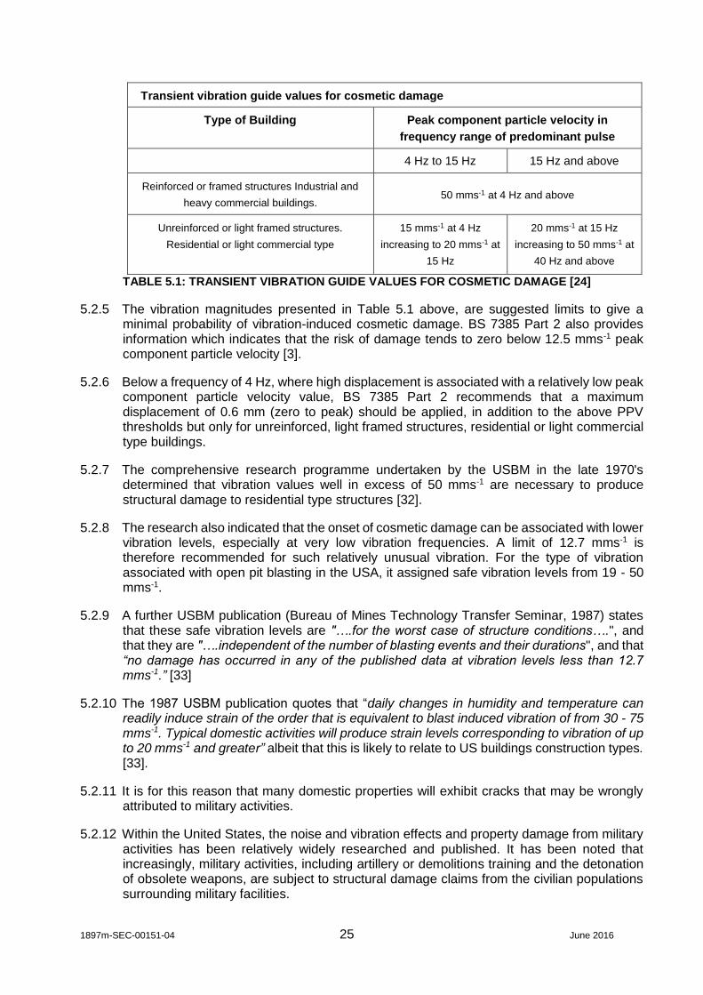
5.2.4 According to BS 7385 Part 2, for residential or light commercial buildings, the threshold for the onset of potential cosmetic damage (i.e. formation of hairline cracks on drywall surfaces or the growth of existing cracks in plaster or drywall surfaces) to buildings varies with frequency. This ranges from a component PPV of 15 mms-1 at 4 Hz, rising to 20 mms-1 at 15 Hz, and to 50 mms-1 at and above 40 Hz.
1897m-SEC-00151-04 25 June 2016
Transient vibration guide values for cosmetic damage
Type of Building Peak component particle velocity in
frequency range of predominant pulse
4 Hz to 15 Hz 15 Hz and above
Reinforced or framed structures Industrial and
heavy commercial buildings. 50 mms-1 at 4 Hz and above
Unreinforced or light framed structures.
Residential or light commercial type
15 mms-1 at 4 Hz
increasing to 20 mms-1 at
15 Hz
20 mms-1 at 15 Hz
increasing to 50 mms-1 at
40 Hz and above
TABLE 5.1: TRANSIENT VIBRATION GUIDE VALUES FOR COSMETIC DAMAGE [24]
5.2.5 The vibration magnitudes presented in Table 5.1 above, are suggested limits to give a minimal probability of vibration-induced cosmetic damage. BS 7385 Part 2 also provides information which indicates that the risk of damage tends to zero below 12.5 mms-1 peak component particle velocity [3].
5.2.6 Below a frequency of 4 Hz, where high displacement is associated with a relatively low peak component particle velocity value, BS 7385 Part 2 recommends that a maximum displacement of 0.6 mm (zero to peak) should be applied, in addition to the above PPV thresholds but only for unreinforced, light framed structures, residential or light commercial type buildings.
5.2.7 The comprehensive research programme undertaken by the USBM in the late 1970's determined that vibration values well in excess of 50 mms-1 are necessary to produce structural damage to residential type structures [32].
5.2.8 The research also indicated that the onset of cosmetic damage can be associated with lower vibration levels, especially at very low vibration frequencies. A limit of 12.7 mms-1 is therefore recommended for such relatively unusual vibration. For the type of vibration associated with open pit blasting in the USA, it assigned safe vibration levels from 19 - 50 mms-1.
5.2.9 A further USBM publication (Bureau of Mines Technology Transfer Seminar, 1987) states that these safe vibration levels are "….for the worst case of structure conditions….", and that they are "….independent of the number of blasting events and their durations", and that “no damage has occurred in any of the published data at vibration levels less than 12.7 mms-1.” [33]
5.2.10 The 1987 USBM publication quotes that “daily changes in humidity and temperature can readily induce strain of the order that is equivalent to blast induced vibration of from 30 - 75 mms-1. Typical domestic activities will produce strain levels corresponding to vibration of up to 20 mms-1 and greater” albeit that this is likely to relate to US buildings construction types. [33].
5.2.11 It is for this reason that many domestic properties will exhibit cracks that may be wrongly attributed to military activities.
5.2.12 Within the United States, the noise and vibration effects and property damage from military activities has been relatively widely researched and published. It has been noted that increasingly, military activities, including artillery or demolitions training and the detonation of obsolete weapons, are subject to structural damage claims from the civilian populations surrounding military facilities.

1897m-SEC-00151-04 26 June 2016
5.2.13 A simple procedure has previously been adopted in the United Sates to assess damage claims that attribute ground vibration to military activities. The procedure utilises empirical equations formulated by the Bureau of Land Management and the mining industry to estimate the peak level of ground vibration caused by the Army activity. A claim is viewed to have merit if the estimated ground peak particle velocity has a value of 25 mms-1 or greater.
5.2.14 It should be noted that for some regulations related to mining in the US, a more stringent threshold value of 12 mms-1 is used, although the threshold value is effectively the level at which claims are investigated, not necessarily an indication of the vibration level at which structural damage to properties might occur.
5.2.15 It is also important to note that the mining industry blasting significantly differs from Army activities, especially in the use of very large explosive charge sizes (typically thousands of pounds of TNT) spread over a relatively large area (to break the most rock).
5.2.16 Thus, the empirical equations currently in use to determine vibration impact, may not be accurate when applied to military activities, which usually involve point sources much smaller in explosive size.
5.2.17 In addition, many military activities, including artillery training and demolitions work sometimes use airborne explosives rather than the buried charges most often used in mining.
5.2.18 The research undertaken during the SERDP SEED project, discussed in Section 2, predicted, using a conservative empirical equation, that the vibrational damage criteria of 12 and 25 mms-1 will be exceeded if the peak positive air overpressure exceeds 480 Pa (147.6 dB) or 1 kPa (154.0 dB), respectively. Both of these levels are higher than the cautious damage thresholds presented and discussed below for air overpressure [31].
Historical buildings or Buildings of Specific Value
5.2.19 Information presented in BS7385: Part 2 regarding important buildings, suggests that buildings which are in a poor state of repair may require special consideration on a case by case basis.
5.2.20 The Standard explains that if a building is in an unstable state, then it will tend to be more vulnerable to the possibility of damage arising from vibration or any other ground-borne disturbance (e.g. settlement).
5.2.21 It also states however that ‘a building of historical value should not (unless it is structurally unsound) be assumed to be more sensitive’ [3].
Continuous Vibration
5.2.22 The guideline values set out in Table 5.1 above relate predominantly to transient vibration. BS 7385 Part 2 states that ‘where the dynamic loading caused by continuous vibration is such as to give rise to dynamic magnification due to resonance, especially at lower frequencies where lower guide values apply, then the guide values in the Table may need to be reduced by up to 50%’.
5.2.23 It also provides a precautionary note which states ‘There are insufficient cases to substantiate these guide values but they are based on common practice’.
5.2.24 The vibration associated with military activities will be transient in nature and therefore a precautionary reduction in threshold values to protect against dynamic loading caused by

1897m-SEC-00151-04 27 June 2016
continuous vibration would not be necessary, however, a reduction has been adopted, to provide a reasonable threshold for assessing damage to vulnerable buildings.
5.2.25 As an example, the Crossrail project in London adopted lower action thresholds than those presented in Table 5.1 above, to protect against continuous vibration and then reduced this threshold further for listed buildings.
5.2.26 The adopted thresholds for the on-set of building damage are presented in Table 5.2.
5.3 Air Overpressure
5.3.1 Several studies have been undertaken to establish reasonable thresholds for the prevention of building damage.
Structural Damage from Air Overpressure
5.3.2 One of the most prominent studies was undertaken by the US Bureau of Mines (‘Structure Response and Damage Produced by Airblast from Surface Mining’, RI 8485) [34] during which a total of 56 different structures were studied for air overpressure and ground vibration response and damage. The study found that in contrast to ground vibration, air overpressure is relatively ineffective at producing whole-structure responses in small structures such as residential homes.
5.3.3 Air overpressure damage criteria were developed from consideration of the ground vibration criteria already defined previously and from statistical comparisons between air overpressure responses and ground vibration responses. Essentially an equivalent damage risk in terms of air overpressure has been derived from the equivalent ground vibration level of 12.7 mms-1 PPV (or higher in some of the analyses conducted). Appreciable magnitudes of groundborne vibration were measured at some sites, due in part, to the measurement sites being within a few thousand feet of the blasts.
5.3.4 Three different analytical methods were used to determine safe air overpressure magnitudes, based on measured corner (structure) responses to both air overpressure and ground vibration. They included a comparison of the mean values of air overpressure and ground-borne vibration plots.
5.3.5 All three approaches resulted in similar air overpressure magnitudes. From the lowest (safest) of the three, overall safe air overpressure criteria, based on structural response and potential damage, were derived. Based on a minimal probability of the most superficial type of damage in typical residential type structures, any of the following represent safe maximum air overpressure magnitudes, according to the USBM:
0.1 Hz high-pass system 134 dB
2 Hz high-pass system 133 dB
5 or 6 Hz high-pass system, 129 dB
C-Slow (events not exceeding 2 second duration 105 dB
5.3.6 The statistical relationship that has been explored for the derivation of the above ‘safe’ maximum air overpressures is based on comparisons between measured mean groundborne vibration passing into the building structure, and corresponding measured air overpressures. The ‘safe’ values above correspond to groundborne vibration of 0.75 in/sec (or 19 mms-1). At significant distances from the blasting activity, where such high magnitudes of groundborne vibration become less likely or even absent, the use of air

1897m-SEC-00151-04 28 June 2016
overpressure thresholds derived empirically in this fashion from relatively high magnitudes of groundborne vibration may not be appropriate.
5.3.7 Furthermore the USBM’s objective with identifying the ‘safe’ maximum air overpressure values was to provide the mining industry with guidance for the design of blasting regimes to enable the adverse effects of structural response to be minimised. In this context the USBM describes the ‘safe’ maximum thresholds as corresponding to essentially zero probability of damage.
5.3.8 In 1983, the Office of Surface Mining and Reclamation Enforcement (OSMRE) (as cited in [35]) addressed air overpressure limits in their regulations. These mirror the criteria set out by the USBM as presented above.
5.3.9 These thresholds are generally considered to be quite conservative as they apply to the potential for actual damage and are aimed at preventative planning by the operators and regulatory authorities. Bender (2007) believes that they have been developed more for reducing human annoyance than to prevent damage to residential structures [35].
5.3.10 This is further supported by information presented consistently in both BS 6472 Part 2 and BS 5228 ‘Code of practice for noise and vibration control on construction and open sites – Part 2: Vibration’ [41], which when referring to structural damage, makes direct reference to the USBM research in [34] and states that:
windows are generally the weakest parts of a structure exposed to air overpressure;
research by the United States Bureau of Mines has shown that a poorly mounted window that is pre-stressed might or can crack at 150 dB (lin), with most windows cracking at around 170 dB (lin); and
structural damage would not be expected at levels below 180 dB (lin).
5.3.11 The British Standards therefore do not recognise the role of the ‘safe’ maximum air overpressure magnitudes in identifying the risk of structural damage from blasting activities. Furthermore, it is notable that BS 6472 states:
“Many of the complaints about vibration from blasting might be due, either in part or entirely, to this air overpressure exciting the elements of the building, rather than groundbome vibration. Subjective separation of ground vibration and the effects of air overpressure is difficult.”
5.3.12 The specification of the monitoring for the primary study includes processes that will enable the full capture of time histories thus allowing the separate analyses of measured groundborne vibration and air overpressure. The presence and influence of groundborne vibration can be determined by considering the differences in signal arrival times at the measurement location.
Mid-wall Response and Window Breakage
5.3.13 Similar comparisons were made by the USBM, between air overpressure and ground-borne vibration-produced mid-wall responses. These studies showed that predicted air overpressure equivalent values calculated from the mid-wall groundborne vibration were lower than the corresponding values from the corner responses, indicating that air overpressure is a relatively efficient generator of mid-wall motion. This can result in a lower tolerance level for air overpressure, with mid-wall motions producing annoyance from secondary rattling of objects, with complaints regarding this typically occurring at levels exceeding 120 dB (6 Hz) [34].

1897m-SEC-00151-04 29 June 2016
5.3.14 This does appear to counter Bender’s claim that the USBM/OSMRE limits have been developed for reducing human annoyance, as the secondary effects described above, would still occur within compliance of these limits.
5.3.15 While not significant for structural damage, mid-wall responses can contribute to glass breakages, which are found to be the first indication of excessive air overpressure.
Additional Research
5.3.16 The USBM RI 8485 [34] study included the review of 18 other studies plus new analysis of air overpressure damage risks.
5.3.17 However, they noted that despite widely varied source characteristics, assumptions of damage probabilities and experimental design, and also differing interpretations among the studies, most of the 21 studies concluded that, for impulsive events damage becomes improbable below approximately 140 dB [34].
5.3.18 Early research by the USBM [42] (as cited in [34]) determined that breakage of window glass in structures should occur at lower levels than other damage. This research evaluated glass breakage from small open air shots consisting of one to two sticks of dynamite. Damage to properly mounted glass is reported to have occurred at overpressures of 170 dB to 172 dB, while none was observed at 167 dB to 168 dB.
5.3.19 Perkins and Jackson (as cited in [42]) also conducted extensive tests. They defined damage threshold for properly mounted glass of 168 dB and for poorly mounted glass of 151 dB. They also noted that rattling of window sashes occurred at 141 dB to 145 dB.
5.3.20 Poulter (as cited in [34]) evaluated glass breakage and plaster damage produced by air overpressure from unconfined explosives. The USBM reports that he found glass damage and plaster damage could occur at approximately 141 and 160 dB respectively. This agrees with other conclusions that plate glass is more damage sensitive than plaster [34].
5.3.21 In order to determine whether ancient structures were more susceptible to vibration caused by air overpressure, limited acoustic trials were carried out on the Otterburn Training Area (OTA) in the late 1990’s in relation to ‘at risk’ ancient structures such as bastles (fortified farmhouses). A Multi-Launch Rocket System (MLRS) was fired in relative close proximity of the bastle and did not result in any observable damage to the structure.
5.3.22 The field trials included measurements of noise and vibration and also observations inside the bastle to determine whether any dust or debris was dislodged during firing. The predicted pressure level was 144 dB (lin) and a measured vibration level of 0.14 mms-1 was achieved on the structure. The predicted force on the bastle was 317 Nm-2 [36].
Sonic Booms
5.3.23 Experimental sonic boom tolerance tests reported by Sutherland (as cited in [37]), provided the following results:
Cracks in plaster on wood lath 144 dB-148 dB
Nail Popping ½ inch gypsum board 148 dB
Paint flaking on old gypsum board 147 dB
Falling bric-a-brac and rattling dishes 143 dB-148 dB

1897m-SEC-00151-04 30 June 2016
5.3.24 Sutherland also reviewed window and other damage from sonic booms. In a study of 24 windows sized 3ft x 3ft, no failures were observed below 154 dB. However pre-cracked windows failed at levels as low as 145 dB.
5.3.25 Having summarised theoretical and experimental studies of sonic boom damage, Sutherland (as cited in [34]) concludes that a sonic boom overpressure of 136 dB would preclude damage, based on theoretical damage calculations of stresses in a structure.
5.3.26 Wiggins (as cited in [34]) analysed sonic boom tests in Oklahoma and White Sands. The lowest value for any event was 134 dB, which caused the fall of a fleck of loose paint. A plaster crack from structure racking was observed at approximately 140 dB, however it was considered that plaster cracks typically required 145 dB to 151 dB. Wiggins also lists cases of glass damage, which typically had thresholds of 146 dB to 152 dB and noted that a significant amount of breakage occurred at 159 dB. Much of the glass damage reported in Wiggins study was attributed to impact of severely rattling window sashes, rather than direct pressure against the panes. Therefore the mechanism for glass failure may be different for windows in loose frames than for glass mounted to be immovable.
5.3.27 One variable which does appear to have a noticeable effect on damage thresholds is the size of the glass windows. Kryter (as cited in [34]) calculated maximum ‘safe overpressures’ for large panes of glass, subjected to sonic booms from four different aircraft. He observed that a low damage threshold was evident for the largest windows, which he claimed is consistent with the matching of their 3 Hz natural frequency with long N-wave duration for large aircraft.
5.3.28 According to Kryter, for a window measuring approximately 2.5m x 5m (139 ft2), a relatively low sonic boom overpressure level of 119 dB, will meet a 10-5 (1 in 100,000) damage probability, although it is noted that this is much larger than most residential windows. It was also noted that a ¼ inch thickness, as used for the tests, was not common in the larger sized windows, with thicknesses of 5/16th inch for an 80 ft2 pane and ½ inch for a 139 ft2 considered normal. Increasing the thickness of the glass would increase their safe thresholds by 2 dB and 5 dB respectively (Seaman as cited in [34]).
Damage Probabilities
5.3.29 An earlier publication by the USBM from 1974, Technical Progress Report 78 [42] by Siskind and Summers, and the more definitive RI 8485 report of 1980 [34], both provide an insight into the statistical damage probabilities which form the basis of the thresholds applied by USBM. At 140 dB the statistical probability of glass breakage for even the largest and hence most vulnerable windows studied indicate a probability of <1 in 5000 when excluding fast jet sonic-boom associated activity. With fast jet aircraft sonic-boom activity included some data which suggests around a <1 in 300 probability at 140 dB.
5.3.30 The appendices to the main USBM study suggest that it may be prudent to apply a 9 dB safety factor, per doubling of window size above 80 ft2 to the ‘safe’ maximum recommended air overpressure of 134 dB to preserve a 10-5 (1 in 100,000) damage probability in the case of sonic booms. However, the research explains that where a higher damage probability is acceptable, this correction is not necessary.
5.3.31 It is also important to note that the Kryter study (as cited in [34]) also showed that frequency affects the safe level, demonstrating that failure probability decreases for sonic booms of frequency higher than that of the window resonance, and consequently surmises that airblasts (as opposed to low frequency fast jet aircraft generated sonic booms) should present a lower damage probability. The USBM report concludes that the apparently greater damage risk from sonic boom is probably an artefact of the analyses, with large populations sampled with few pre-boom damage inspections.

1897m-SEC-00151-04 31 June 2016
5.3.32 The main USBM study findings for various ‘safe’ airblast and sonic boom damage criteria are stated to be based upon no greater damage risk than 1 chance in a 1,000. It has been assumed therefore that this level of probability is regarded as being synonymous with a ‘safe’ maximum by the researchers. Inspection of the glass damage summary data presented in the USBM report suggests that even with fast jet sonic boom data for large windows included, a level of 134 dB represents a damage risk probability of approximately 1 in 2000, and this reduces to approximately 1 in 20,000 with the sonic boom data excluded.
5.4 Fatigue Damage
5.4.1 Research and previous work undertaken has indicated that any vibration induced damage will occur immediately if the damage threshold has been exceeded and if there is no evidence of other long term effects.
5.4.2 British Standard 7385 Part 2 states that there is little probability of fatigue damage occurring in residential building structures due to blasting. The increase of the component stress levels due to imposed vibration is relatively nominal and the number of cycles applied at a repeated high level of vibration is relatively low. Non-structural components (such as plaster) should incur dynamic stresses which are typically well below, i.e. only 5% of, component yield and ultimate strengths.
5.4.3 The US Bureau of Mines [37] undertook testing on a wooden framed house, built in the path of an advancing coal mine. Structural fatigue and damage were assessed over a two year period. The house was subjected to vibrations from 587 separate production blasts with particle velocities that varied from 2.5 mms-1 to 176 mms-1. Later, the entire house was shaken mechanically to produce fatigue cracking.
5.4.4 Cosmetic or hairline cracks 0.01 mm to 0.10 mm wide occurred during the construction of the house and also during periods when no blasts were detonated. The formation of cosmetic cracks increased from 0.3 to 1.0 cracks per week when ground motions exceeded 25.4 mms-1. Human activity and changes in temperature and humidity conditions caused strains in walls that were equivalent to those produced by ground motions up to 30mms-1. When the entire structure was mechanically shaken, the first crack appeared after 56,000 cycles, the equivalent of 28 years of shaking by blast generated ground motions of 12.7 mms-1 twice a day [37].
5.4.5 It is also important to note that this and other research on blasting, principally relates to work carried out for the working of surface minerals where the explosive is detonated within a bored hole. Accordingly, vibration travels directly through the ground and the acoustic emission occurs as air overpressure. In this respect it may be different to many military sources where the activity either occurs above ground level or on the surface of the ground and therefore the extent to which vibration travels through the ground will be limited, although it should be acknowledged that some buried detonations do occur on military bases.
5.5 Summary of Damage Criteria
5.5.1 In consideration of the above information, thresholds for the study which include those for the onset of potential damage from ground-borne vibration and air overpressure have been established.
5.5.2 The thresholds are presented in Tables 5.2 and 5.3 for vibration and air overpressure respectively. Table 5.3 presents a compendium of thresholds from the available guidance and research.

1897m-SEC-00151-04 32 June 2016
TRANSIENT VIBRATION THRESHOLDS FOR THE ON-SET OF COSMETIC DAMAGE
TYPE OF BUILDING
MAXIMUM DISPLACEMENT
PEAK COMPONENT PARTICLE VELOCITY IN FREQUENCY RANGE OF PREDOMINANT PULSE
Less than 4 Hz Less
than 4Hz 4 Hz to 15 Hz 15 Hz and above
Reinforced or framed structures Industrial and heavy commercial
buildings[1] [2] [3] 50 mms-1 at 4 Hz and above
Unreinforced or light framed structures. Residential or light
commercial type[1]
0.6 mm zero to peak[1]
[3]
15 mms-1 at 4 Hz increasing to 20 mms-1 at
15 Hz
20 mms-1 at 15 Hz increasing to 50 mms-1
at 40 Hz and above
Precautionary Thresholds Adopted[4]
Any building[5]
0.6 mm zero to peak[1]
12.5 mms-1
Vulnerable Structures[6]
6 mms-1
TABLE 5.2: GROUND-BORNE VIBRATION THRESHOLDS FOR ON-SET OF COSMETIC DAMAGE TO BUILDINGS Notes: [1] – Following guidance from BS 7385-2 [2] – damage thresholds for maximum displacement below 4 Hz for reinforced or framed structures and heavy commercial buildings are not defined in BS 7385-2. [3] – damage thresholds for PPV below 4 Hz for any building type are not defined in BS 7385-2 [4] – Cautious thresholds adopted for this study which do not indicate a level above which damage will occur, rather they offer a precautionary level at which further consideration may be required. [5] - probability of damage tends towards zero at 12.5 mrns-1 peak component particle velocity (BS7385-2). [6] – reduction in PPV threshold levels for vulnerable structures based on precautionary principles applied on recent major UK infrastructure projects.

1897m-SEC-00151-04 33 June 2016
Air Overpressure Threshold Scale[1,7]
dB (lin)
Categorisation Source
180[6] Onset of structural damage BS 6472, BS 5228
171[5] General window breakage USBM [34]
170 Most windows crack BS 6472, BS 5228
160 Cracking of pre-stressed or poorly mounted windows
BS 6472, BS 5228
151[4] Some window breakage USBM [41]
150 Pre-stressed or poorly mounted windows may crack
BS 6472, BS 5228
140[3] Reasonable threshold to prevent glass and plaster damage
USBM [34]
134[2] USBM ‘Safe’ maximum USBM [34]
120 Secondary vibration effects including rattling windows and objects
BS 6472, BS 5228, USBM [34]
<120 No material effect -
TABLE 5.3: AIR OVERPRESSURE THRESHOLDS FOR DAMAGE EFFECTS ON BUILDING STRUCTURE Notes: [1] – Compendium of advised thresholds from BSi and USBM sources. [2] – USBM [34]. Level based on measurements with high pass filtering at 0.1 Hz. Precautionary advice for design of blasting, pre-supposes groundborne vibration components. Not recognised by BSi. Included for information. [3] – USBM [34] – ‘Despite the widely varied source characteristics, assumptions of damage probabilities and experimental design, and also the differing interpretations among the studies, there is a consensus that damage becomes improbable below approximately 140 dB’. [4] - Perkins and Jackson (as cited in USBM [42]) – damage thresholds for ‘poorly mounted glass under stress’ [5] – USBM [34] – ‘Damage to properly mounted glass is reported to have occurred at overpressures of 170 dB to 172 dB, while none was observed at 167 dB to 168 dB’. Mean value of 171 adopted. [6] – BS 6472 -2. ‘Structural damage would not be expected at air overpressure levels below 180 dB(lin)’. [7] – Shaded entries originate from primary sources of information and are recommended for application to the main study.
5.5.3 Based upon the guidance in the relevant British Standards, and inspection of the
background to the research conducted by the USBM in deriving the ‘safe’ maximum thresholds, it is considered that whilst these thresholds may have a role in maximising the protection against potential building damage where appreciable magnitudes of groundborne vibration are present and/or there is a requirement to regulate the prevalence of annoyance to the buildings occupants, they should be applied cautiously to situations where the primary concern is the risk of damage due solely to air overpressure.
5.5.4 The ‘safe’ maximum threshold used for blast regime planning is nevertheless recommended to be included in this study for information whilst recognising that there is a consensus that damage becomes improbable below approximately 140 dB by the same authors.

1897m-SEC-00151-04 34 June 2016
6. MEASUREMENT AND MONITORING OF MILITARY ACOUSTIC EFFECTS
6.1 Scope
6.1.1 The purpose of this section has been to review the available measurement and monitoring resources and determine an acceptable measurement methodology for sound pressure, air overpressure and ground-borne vibration. The aim is to ensure that any measurement strategy reduces uncertainty and where all other aspects are controlled, should result in repeatable measurements.
6.2 Ground-borne Vibration
Measurement Parameters
6.2.1 As indicated in Section 4, PPV’s are considered to be the most appropriate parameter for measuring ground-borne vibration levels with respect to potential damage of structures as recommended by the British Standards Institution and other researchers.
Frequency Response
6.2.2 Most building damage from man-made sources occurs in the frequency range from 1 Hz to 150 Hz according to BS ISO 4866 [2].
6.2.3 The typical range of vibration frequency for blast-induced vibration is from 5 Hz to 40 Hz [1].
6.2.4 Vibration measuring equipment or seismographs should therefore be able typically to measure over the amplitude range of 0.1 mms-1 to 100 mms-1 over the frequency range 1 Hz to 250 Hz [1].
Measurement Locations and Direction
6.2.5 BS 7385 Part 2 states that ‘measurements should be taken at the base of the building on the side of the building façade facing the source of vibration, to define the vibration input to the building. Where this is not feasible, the measurement should be obtained on the ground, outside of the building. One of the horizontal vibration components should be in the radial direction between the source and the building in the case of ground measurements or oriented parallel with a major axis of the building when investigating structural response’ [3].
6.2.6 In general, transducers should be coupled to the vibrating medium (ground, foundation, floor) so that they faithfully respond to the motion relative to the focus of the investigation.
6.2.7 According to BS ISO 4866, measurements of vibration response generated by traffic, pile driving and blasting, especially at great distance, show that vibration may be amplified within the building and in proportion to the height of the building. BS ISO 4866 indicates therefore that it may be necessary to carry out simultaneous measurements at several points within a building [2].
Mounting of Transducers
6.2.8 Transducers should be mounted to respond faithfully, to the vibration in the frequency and magnitude ranges in which the excitation may be expected.
6.2.9 According to the Association of Noise Consultants (ANC), measurements should be made outside the building on a well-founded hard surface as close to the building as possible. Alternatively transducers may be buried if no such surface is available [38].

1897m-SEC-00151-04 35 June 2016
6.2.10 Different methods of coupling and the guidance to ensure correct installation, are presented below in Table 6.1:
Type of Coupling Guidance
Ground Spikes Should be less than 0.4m in length to avoid natural frequencies within the frequency range of interest.
Should be greater than 0.2 m in length to ensure adequate coupling between transducer and ground.
Should be greater than 10 mm in diameter to ensure good contact with the surrounding medium and to resist rotation.
Steel angle sections minimise rotation; however, these are more difficult to drive particularly in made ground and spikes may produce better contact with the ground although they can be subject to rotation.
Metal Plate A metal plate (often known as a DIN plate) can be used as long as it has sufficient mass to remain coupled to the measurement surface.
It should have a method of transducer fixing, i.e. mounting bracket bolted to it, and interchangeable feet (spikes for carpets; buttons for hard surfaces). For measurements on open ground, this can be part buried to ensure good contact with the ground.
Block Must have sufficient plan area and mass to ensure stable mounting for transducer (to minimise rocking effects)
Must not be too large (will distort local ground response)
Use stud to affix transducer to block or very rigid glue (e.g. cement glue) to avoid transducer resonance falling into frequency range on interest.
Cast in ground blocks (patch) Cast concrete, plaster of Paris or appropriate material into small excavation to produce a ‘patch’
At the same time, paste small mounting block with stud to fix transducer into ‘patch’
Use quick setting material.
Vary density of material to ‘match’ that of surrounding ground.
N.B. Results are specific to the mass and geometry of the material
Buried transducer Extreme care required to ensure orientation of transducer, care required to ensure that compaction of backfill is adequate and controlled to ensure coupling of transducer to ground and reflect the surrounding ground conditions.
Care required where the material has large (granular) particle size. Extreme care required to avoid poor repeatability.
TABLE 6.1: METHODS OF MOUNTING TRANSDUCERS [38]

1897m-SEC-00151-04 36 June 2016
Type of Coupling Guidance
Existing ‘buried’ structure Use very rigid glue or stud to fix transducer.
Evaluate the dimensions and material of structure and quantify structure vibration response characteristics. (N.B. this will not yield free field vibration levels).
The vibration measurements obtained then need to be adjusted using transfer functions for the floors and surfaces of the new building.
TABLE 6.1(CTD): METHODS OF MOUNTING TRANSDUCERS [38]
6.2.11 Information presented by Bender [35] during a workshop for the International Society of Explosives Engineers provides the following direction for geophone placement.
‘The geophone should be located on the ground near to the base of the structure to be protected. Optionally, it can be located at an interim site closer to the blast in the case of great distance and/or small charge weights. If at all possible, record on original ground rather than fill’.
6.2.12 Bender goes on to state:, ‘Do not record blast vibration….
On structures (unless that is the only possible location or is mandated);
Over hollow spaces or areas of subsidence;
Immediately adjacent to posts, poles or any other object that could oscillate and
contribute to the motion in that specific location;
On grass, leaves, mulch, planter mix, loose soil or near trees and their roots.’
Measurement Duration
6.2.13 The measurement of vibration should be made over a period of sufficient duration to capture representative events, (often of the highest magnitude). The actual duration of measurement would therefore depend on the characteristic of vibration input, the frequency of the vibration events and the response of the structure under investigation [38].
Data Requirements
6.2.14 The amount of information required to characterise vibration increases as the complexity of the vibration increases. Data collections which are adequate for defining a periodic motion over a specified frequency range may not be adequate for establishing even a single parameter index (such as PPV) for a more complex motion.
6.2.15 When considering building response, the ANC recommend the following be recorded:
a. The maximum PPV including peak component and peak true resultant;
b. Individual time histories and duration of vibration; and
c. Predominant frequencies in time histories and frequency spectra.

1897m-SEC-00151-04 37 June 2016
6.3 Air Overpressure
6.3.1 A number of difficulties have been noted with respect to the measurement of air overpressure from military noise events and these include:
The requirement to accurately detect and classify military noises;
Wind noise on the microphone can interfere with the military noise event ;
Where logs of military noise events are not correlated with the recording of noise
events, there can be an unacceptable amount of ‘possible’ events reported;
Where military noise events occur below a specified peak noise level (aimed at
capturing all situations) then the data will not be captured.
6.3.2 It is very important therefore, that the correct measurement equipment and procedures are used when studying air overpressure magnitudes.
Measurement Parameters
6.3.3 Overpressure is usually expressed, Pascals or Kilopascals (Pa, kpa), or in decibels (dB). Peak pressures are usually reported in terms of decibels, which are defined as:
dB = 20log10(p/po)
where p is measured peak sound pressure and po is a reference of 20 x 10-6 Pa).
6.3.4 According to the USBM, the instrument used for measuring air overpressure should be a Type 1 impulse, precision instrument, able to record a complete time history from which a peak measurement can be obtained [34].
6.3.5 An impulse weighting is usually classified as having a 35 ms rise time and 1500 ms decay time. This would be considered the minimum requirement for any instrument used for measuring peak air overpressures.
6.3.6 In addition, any equipment used to measure air overpressure must have an adequate low frequency response to capture fully the dominant low frequency component [1]. USBM indicates that for confined blasts a frequency range of 0.1 to 200 Hz would suffice.
6.3.7 However, it also states that for unconfined blasts, which would be similar to those experienced at military ranges, a range of 0.05 Hz to 1 kHz would be required.
6.3.8 The human ear is less sensitive to low frequency sounds compared to mid frequencies. The military effects are commonly in the low frequency band, particularly at larger distances. Due to the sensitivity of human hearing, the A-weighting has been developed to mask the insensitivity at the lower frequencies.
6.3.9 As such, for the measurement of high intensity low frequency noise events, such as blast noise, the A-weighted scale can underemphasise the response to the noise (which is perceived not only through the ear, but also as secondary vibration).
6.3.10 Therefore the preferred parameter, according to BS 6472 Part 2, for measuring air overpressure magnitudes, is to use linear response, (dB Lin) due to dominant low frequency content [1].
6.3.11 Owing to the extremely low frequencies generated, BS 6472 Part 2 recommends that a 2 Hz high-pass system with an almost flat response down to 2 Hz should be used [1].

1897m-SEC-00151-04 38 June 2016
6.3.12 The standard states that if measurements include frequencies of less than 2 Hz they can be greatly distorted by even the slightest pressure changes, which can be caused by the gentlest of wind or people walking past the microphone [1]. However, research undertaken by the USBM supports the use of measurements down to 0.1 Hz as air blasts contain significant proportions of energy below 2 Hz.
6.3.13 The USBM suggests that the frequency response of the monitoring equipment should meet or exceed the following specifications:
0.1 Hz peak instrumentation 0.1 – 200 Hz +/- 3 dB
2 Hz peak instrumentation 2 – 200 Hz +/- 3 dB
5 Hz peak instrumentation 5 – 200 Hz +/- 3 dB
C-slow ANSI s1.1-1971 (Type 1 meter)
6.3.14 It is suggested that for research tests, the lower limit should meet or exceed 0.1 Hz, however it acknowledges that equipment with measurement ranges down to 0.1 Hz are expensive and advocates measurements using 2 Hz peak instrumentation.
6.3.15 The International Society of Explosives Engineers, in their ‘Field Practice Guidelines for Blasting Seismographs’ (ISEE 2009) [39] requires that air overpressure microphones should conform to the following minimum values:
Frequency range 2 to 250 Hz, -3 dB at 2 and 250 Hz, ±1dB
Accuracy ±1 dB between 4 and 125 Hz.
Microphone seismic sensitivity Microphone response to a mechanical vibration of 50 mms-1 at 30 Hz, from any angle, must be less than 40 dB below the maximum microphone output, or 106 dB whichever is lower.
Microphone Placement
6.3.16 The USBM indicates that the microphone should be at least 0.9m above local ground level and to the side of the structure to minimise reflections. Orientation of the microphone is of minor importance as it is directional only at high frequencies and essentially omnidirectional at the event-generated frequencies.
6.3.17 The ISEE (2009) recommend the following:
The microphone should be placed along the side of the structure, nearest the blast.
The microphone should be mounted near the geophone with the manufacturer’s
wind screen attached.
The microphone may be placed at any height above the ground.
6.3.18 Enhanced windscreens should be used to reduce wind effects over the microphone.
6.3.19 If practical, the microphone should not be shielded from the blast by nearby buildings, vehicles or other large barriers. If such shielding cannot be avoided, the horizontal distance between the microphone and shielding object should be greater than the height of the shielding object above the microphone.

1897m-SEC-00151-04 39 June 2016
6.3.20 If placed too close to a structure, the air overpressure may reflect from the house surface and record higher amplitudes. Structure response noise may also be recorded. Reflection can be minimised by placing the microphone near a corner of the structure.
6.3.21 The orientation of the microphone is not critical for air overpressure frequencies below 1,000 Hz.
6.3.22 Eltschlager, K et al (2005) [40] undertook a study of air overpressure measurements taken at different heights. Near and far field measurements were taken to obtain representative spectral and amplitude ranges.
6.3.23 The comparative analysis shows that microphone height has negligible impact on air overpressure measurements.
Recording Air Overpressure
6.3.24 Bender (2007) suggests that when recording air overpressure ‘always include the recording of the airblast. Structures may respond to airblast that you cannot readily hear and can result in creaking, rattling or other internal noises. Many blast vibration complaints are actually the result of airblast-induced structure motion rather than ground vibration’.
6.3.25 Bender also advises the use of a trigger mechanism, in order to make sure the event is recorded. A low trigger level is recommended to ensure the events are captured

1897m-SEC-00151-04 40 June 2016
7. SUMMARY OF FINDINGS
7.1.1 The purpose of this review is to ensure that both the measurement and assessment stages of the main study are based upon robust and contemporary methodologies. The following primary objectives have been identified:
identify the physical mechanisms and acoustic characteristics of activities which are undertaken on MOD land ranges and how these may give rise to potential structural damage;
provide best practice guidance for the measurement of sound pressure, air overpressure and ground-borne vibration from military land range activities at far-field receptor locations; and
develop an understanding of the magnitudes of sound pressure, air overpressure and ground-borne vibration which could potentially give rise to potential structural damage.
7.1.2 This report has identified the primary activities which take place on MOD land ranges, and described the different types of likely acoustic events produced by these activities.
7.1.3 The key acoustic effects influencing the impact on structure, including sound pressure, air overpressure and ground borne vibration have been considered in detail. Further information also been provided on the understanding of low frequency sound, infrasound and secondary noise and combined effects.
7.1.4 It has then been shown that the magnitude of sound pressure, air overpressure and ground-borne vibration for a given acoustic event at a given location is dependent on the level of influence of the factors which affect acoustic propagation between source and receptor. These factors have been considered in detail, as have the interaction between acoustic events and building response.
7.1.5 An introduction to the concept of vibration induced building damage is provided, followed by a review of current literature on magnitudes of air overpressure and ground-borne vibration likely to cause building damage. The review has indicated that vibration levels in excess of 12.5 mms-1 and pressure levels at 140 dB (lin) are required for the on-set of potential cosmetic damage in standard residential buildings, although it has also been established that vulnerable or structurally unsound buildings may be subject to damage at lower levels and therefore lower precautionary levels may be required to protect against damage.
7.1.6 Based on a minimal (or essentially zero) probability of the most superficial type of damage in typical residential type structures, a level of 134 dB (lin) (measured with a 0.1 Hz high pass system) represents a precautionary ‘safe’ maximum air overpressure magnitude promulgated by the US mining industry for designing blast regimes, assuming that groundborne vibration is a primary factor, and a need to provide a level of protection to building occupants from annoyance. It is included in this study for information only.
7.1.7 For the purposes of assessing the likelihood of building damage from land range military activities, the thresholds set out in Tables 5.2 and 5.3 are recommended for use.
7.1.8 Finally a review of the methodology and equipment requirements for undertaking robust measurements of sound pressure, air overpressure and ground-borne vibration has been reported.

1897m-SEC-00151-04 41 June 2016
8. REFERENCES
1. British Standard 6472 Part 2: 2008. Guide to Evaluation of human exposure to vibration in
buildings Part 2: Blast-induced vibration.
2. British Standard ISO 4866. 2010: Mechanical vibration and shock. Vibration of fixed
structures. Guidelines for the measurement of vibrations and evaluation of their effects on
structures.
3. British Standard 7385: Part 2 1993: ‘Evaluation and Measurement for Vibration in Buildings’.
4. British Standard 5228: Part 2 2014:
5. MOD Corporate Environmental Protection Manual: 2010. Environmental Noise. JSP 418
Leaflet 4.1
6. Environmental Protection Act 1990 Part III. London: The Stationery Office
7. MOD Corporate Environmental Protection Manual: 2010. Statutory Nuisance. JSP 418
Leaflet 4
8. Otterburn Training Area: AS90 Firing Plan HL Deb 01 February 1995 vol 560 cc114-5WA
9. Hogg, D.J. 2004. An Assessment of Environmental Vibration Produced During Explosive
Activities at Shoeburyness, Essex From January 2003 to March 2004. Vibrock
RO4.3760/2/DJH
10. Gammell, C. 2010. Military testing site 'damaging local homes' The Telegraph. November.
Available [http://www.telegraph.co.uk/news/uknews/8154074/Military-testing-site-
damaging-local-homes.html].
11. MOD. 2014. Noise Amelioration Scheme (Military). MOD
12. Ministry of Defence. Available https://www.gov.uk/government/organisations/ministry-of-
defence.
13. North Atlantic Treaty Organisation. 2010. Hearing Protection – Needs, Technologies and
Performance. NATO.
14. C.S. Wardle,T.J. Carter, G.G. Urquhart, A.D.F. Johnstone, A.M. Ziolkowski, G. Hampson,
D. Mackie. 2001. Effects of seismic air guns on marine fish. Pergamon.
15. Department for Defence Noise Working Group. 2013. Technical Bulletin. An overview of Blast Noise: Characteristics, Assessment and Mitigation. DNWG.
16. Markula. T., 2006. Propagation, measurement and assessment of shooting noise.
Department of Electrical and Communications Engineering Laboratory of Acoustics and
Audio Signal Processing.
17. Pierce, A. 1981. Acoustics. An introduction to its physical principles and applications. 1st
Edition. McGraw-Hill Book Company.
18. Pater, L., Mifflin, A., Broska, K.A., Russell, W.A. 2007. Assessing and Controlling Blast
Noise Emission: Final Report, ESTCP Project SI-0006. Environmental Security Technology
Certification Program.
19. Hay, P.R. n.d How the Ramjet Engine Works. Available [Online]
http://www.okieboat.com/How%20the%20ramjet%20works.html
20. Paakkonnen, R., Parri, A., Tiili, J. 2001. Low-frequency noise emission of Finnish large
calibre weapons. Journal of low-frequency noise, vibration and active control. 20(2) pg 80.
21. Paakkonnen, R.1994. Noise Attenuation of Structures against Impulses from Large Calibre
Weapons or Explosions. Applied Acoustics 45 (1995) 263-218
22. DEFRA. 2001. Low Frequency Noise – Technical Research Support for DEFRA Noise
Programme. DEFRA
23. Ratcliff, J., Sheehan, E., Carte, K. 2001. Predictability of airblast at surface coal mines in
West Virginia. Department of Environmental Protection Office of Explosives and Blasting.

1897m-SEC-00151-04 42 June 2016
24. Edward T. Nykaza, E.T., Luz, G.A., Pater, L.L. 2008. Field research on the assessment of
community impacts from large weapons noise. 9th International Congress on Noise as a
Public Health Problem (ICBEN).
25. Stagg. M.S., Eagle. A.J. Measurement of Blast Induced Ground Vibrations and
Seismograph Calibrations. USBM RI 8506.
26. British Standard 5885-2: 2009+A1:2014 Code of practice for noise and vibration control on
construction and open sites. Vibration
27. ISO 9613-1:1993. Acoustics -- Attenuation of sound during propagation outdoors -- Part 1:
Calculation of the absorption of sound by the atmosphere.
28. Benon-Blanc, B., Lipkens, B., Dallois, L,. Hamilton, M, Blackstock, D. 2002. Propagation of
finite amplitude sound through turbulence: Modelling with geometrical acoustics and the
parabolic approximation. Acoustical Society of America.
29. Abdel-Rasoul, E.I. 2000. Measurement and analysis of the effect of ground vibrations
induced by blasting at the limestone quarries of the Egyptian cement company. Cairo
University.
30. Albert, D.G., Taherzadeh, S., Attenborough, K., Boulanger, P., Decato, S.N. 2013. Ground
vibrations produced by surface and near-surface explosions. US Army Corps of Engineers.
31. Albert, D.G., Attenborough, K., Boulanger, P., White, M.J. 2006. Evaluation of Ground
Vibrations Induced by Military Noise Sources. US Army Corps of Engineers.
32. Siskind, D.E., Stagg, M.S., Kopp, J.W., Dowding, C.H. n.d. Structure Response and
Damage Produced by Ground Vibration from Surface Mine Blasting. USBM RI 8507.
33. Stagg, M.S., Siskind, D.E. 1987. Effects of Blast Vibration on Construction Material Cracking
in Residential Structures (in Surface Mine Blasting) - USBM Technology Transfer Seminar.
34. Siskind D.E., Stachura V.J., Stagg, M.S., Kopp, J.W. 1980. Structure Response and
Damage Produced by Airblast from Surface Mining. USBM RI 8485.
35. Bender, W.L., 2006. Understanding Blast Vibration and Airblast, their Causes, and their
Damage Potential.
36. Parry, G. 1997. Non-Statutory Local Inquiry under Department of the Environment Circular
18/84 Part IV.
37. Stagg. M.S., Siskind. D.E., Stevens. G., Dowding. C.H. 1984. Effects of Repeated Blasting
on A Wood-Frame House. USBM.
38. Association of Noise Consultants. 2012. Measurement and Assessment of Ground-borne
Noise and Vibration. ANC.
39. International Society of Explosives Engineers 2009. Field Practice Guidelines for Blasting
Seismographs. ISEE 2009
40. Eltschlager, K.K. 2005. Microphone Height Effects on Blast-Induced Air Overpressure
Measurements. ISEE 2005
41. British Standard 5228-2:2009 + A1:2014 Part 2 Code of practice for noise and vibration
control on construction and open sites – Part 2: Vibration.
42. Siskind D.E., Summers C.R. 1974. Blast Noise Standards and Instrumentation. USBM
Technical Progress Report 78.

1897m-SEC-00151-04 43 June 2016
APPENDIX A

1897m-SEC-00151-04 44 June 2016
Glossary of Acoustical Terms
Acceleration – rate of change of velocity (in m/s2);
Accelerometer – a transducer which measures acceleration;
Acoustic calibrator – a device for producing an accurately known sound pressure level;used for
the calibration of sound level meters;
Acoustic particle velocity- the velocity of a vibrating particle in an acoustic wave;
Airborne Sound – sound or noise radiated directly from a source, such as a loudspeaker or
machine, into the surrounding air (in contrast to structure-borne sound);
Ambient noise – the totally encompassing noise in a given situation at a given time; it is usually
composed of noise from many sources, near and far;
Amplitude – the maximum value of a sinusoidally varying quantity;
Audibility – the ability of a sound to be heard; the concept of audibility has been used as a criterion
for setting limits to noise levels, particularly from amplified music; it is a subjective criterion, ie one
which can only be determined by the ear of the listener, not by measurement of sound levels; also
used as a criterion to determine the degree of privacy between rooms (e.g offices);
Audibility Threshold – the minimum sound pressure which can just be heard at a particular
frequency by people with normal hearing; usually taken to be 20 µPa at 1000Hz;
Audible range – frequencies from 20 Hz to 20 kHz (approx.); sound pressures from 20 µPa to 100
Pa (approx.);
A weighting – a frequency weighting devised to attempt to take into account the fact that human
response to sound is not equally as sensitive to all frequencies; it consists of an electronic filter in
a sound level meter, which attempts to build in this variability into the indicated noise level reading
so that it will correlate , approximately, with human response;
Broadband – containing a wide range of frequencies;
C weighting - on of the frequency weightings defined in BS 5969; it corresponds to the 100-phon
contour and is the closest to the linear or unweighted value;
dB(A) – the A weighted sound pressure level; (see under a weighting);
Decibel (dB) – the decibel scale is a scale for comparing the ratios of two powers, W1 and W2 is N
dB, where N = 10log10 (W1 /W2); the decibel scale may aslo be used to compare quantities, whose
squared values may be related to powers, including sound pressure, vibration displacement,
velocity or acceleration, voltage and microphone sensitivity; in these cases the difference in level
between two signals, of magnitude S1 and S2, is given by N = 20log10 (S1 /S2); the decibel scale may
be used to measure absolute levels of quantities by specifying reference values which fix one point
in the scale (0 dB) in absolute terms; a decibel is one-tenth of a bel;
Frequency – of a sinusoidally varying quantity such as sound pressure or vibration displacement;
the repetition rate of the cycle, i.e. the reciprocal of the period of the cycle, the number of cycles
per second; measured in hertz (Hz);
Frequency weighting – an electronic filter built into a sound level meter according to BS 5969 (see
also under A and C weighting);
Hearing Level – a measured threshold of hearing, expressed in decibels relative to a specified
standard threshold for normal hearing;
Hertz (Hz) – the unit of frequency; the number of cycles per second;
High pass filter – a filter which transmits frequency components of a signal that are higher than a
certain cut-off frequency but which attenuates those below the cut-off;
Impact noise – sound resulting from the collision between colliding bodies;
Impulse – a transient signal of short duration; impulsive noise is often described by words such as
bang, thump, clatter;

1897m-SEC-00151-04 45 June 2016
Infrasound – acoustic waves with frequencies below the audible range, i.e. below about 20 Hz;
L (level) – sound pressure level, SPL; in general, it implies the use of decibels related to the ratio
of powers, or power-related quantities such as sound intensity or sound pressure;
LAeq, T – (see under continuous equivalent sound level);
LAmax – the maximum RMS A weighted sound pressure level occurring within a specified time period;
the time weighting, fast or slow, is usually specified;
Lpeak – (see under peak sound pressure level);
Linear – a measurement device is linear if its output is directly proportional to its input; in the case
of a microphone, for example, this means that the sensitivity is constant and does not change with
sound pressure level; linear SPL means unweighted.
Loudness – the measure of the subjective impression magnitude or strength of a sound;
Natural frequency – the frequency of free or natural vibrations of a system;
Noise – unwanted sound or unwanted signal (usually electrical) in a measurement or
instrumentation system;
Particle velocity – (see under acoustic particle velocity);
Reflection – the redirection of waves which occurs at a boundary between media when the size of
the boundary interface is large compared with the wavelength;
Refraction – the change in direction of waves caused by changes in the wave velocity in the
medium;
Resonance Frequency – the frequency at which resonance occurs, i.e. at which the forced
vibration amplitude in response to a force of constant amplitude is a maximum ; for an undamped
system the resonance frequency is the same as the natural frequency of the system; for a damped
system the resonance frequency is slightly reduced;
Sound – (1) pressure fluctuations in a fluid medium within the (audible) range of amplitudes and
frequencies which excite the sensation of hearing; (2) the sensation of hearing produced by such
fluctuations;
Sound Level – a frequency-weighted sound pressure level, such as the A-weighted value;
Sound Level Meter – an instrument for measuring sound pressure levels;
Sound Pressure – the fluctuations in air pressure, from the steady atmospheric pressure, created
by sound, measured in Pascals (Pa);
Structure-borne sound – sound which reaches the receiver after travelling from the source via a
building or machine structure; structure-borne sound travels very efficiently in buildings, and is more
difficult to predict than airborne sound;
Subjective – depending upon the response of the individual;
Ultrasound – acoustic waves with frequencies which are too high to be heard by human ears;
Unweighted sound pressure level – a sound pressure level which has not been frequency
weighted, sometimes known as the linear sound pressure level; symbol Lp;
Velocity – the rate of change of displacement, measured in m/s or mm/s;
Vibration – a to-and –fro motion; a motion which oscillates about a fixed equilibrium position
Vibration dose value, VDV – a measure of vibration exposure; the fourth root of the integral, over
the measurement period, of the fourth power of the frequency-weighted time-varying acceleration;
Wave – in an elastic medium; a mechanism whereby a disturbance, and the energy associated with
it, is propagated through an elastic medium; the disturbance results in vibrations of the particles of
the medium, vibrations transmitted to nearby regions as a result of the elastic and inertial nature of
the medium, resulting in a disturbance which is a function of both position and time;
Wavelength – the minimum distance between two points that are in phase within a medium
transmitting a progressive wave;
Whole-body vibration – Vibration transmitted to the body as a whole;

1897m-SEC-00151-04 46 June 2016
APPENDIX B

1897m-SEC-00151-04 47 June 2016
BIBLIOGRAPHY
Documents which have been included in the literature review are detailed below. In some instances they are primary sources whereas for others they are secondary sources where the content is not necessarily directly related to military noise and vibration or effects on buildings.
1. Abdel-Rasoul, E.I. 2000. Measurement and analysis of the effect of ground vibrations
induced by blasting at the limestone quarries of the Egyptian cement company. Cairo
University.
2. Albert, D.G., Taherzadeh, S., Attenborough, K., Boulanger, P., Decato, S.N. 2013. Ground
vibrations produced by surface and near-surface explosions. US Army Corps of
Engineers.
3. Albert.D, et al.2008. Evaluation of Ground Vibrations induced by Military Noise Sources.
US Army Corps of Engineers
4. Association of Noise Consultants. 2012. Measurement and Assessment of Ground-borne
Noise and Vibration. ANC.
5. Australian and New Zealand Environmental Council.1990. Technical Basis for Guidelines
to Minimise Annoyance Due To Blasting Over pressure And Ground Vibrations. Australian
and New Zealand Environmental Council
6. Bender, W.L., 2006. Understanding Blast Vibration and Airblast, their Causes, and their
Damage Potential.
7. Benon-Blanc, B., Lipkens, B., Dallois, L,. Hamilton, M, Blackstock, D. 2002. Propagation of
finite amplitude sound through turbulence: Modelling with geometrical acoustics and the
parabolic approximation. Acoustical Society of America.
8. Birch.W, et al. Theme 1 - Reducing the environmental effect - Reducing the environmental
effect of aggregate quarrying; dust, noise and vibration. Sustainable Aggregates
9. Brink.M, et al.2008. Community response to military shooting noise immissions -
Preliminary results. 9th International Congress on Noise as a Public Health Problem
(ICBEN)
10. Brinkmann.H.2000. Techniques and Procedures for the Measurement of Impulse Noise.
Wehrtechnische Dienstelle fur Waffen und Munition
11. Brisby.G.B. 1997.Sound Pressure Levels For Explosives
12. British Standard 5228: 2009+A1 2014 Code of practice for noise and vibration control on
construction and open sites – Part 2: Vibration
13. British Standard 6472 Part 2: 2008. Guide to Evaluation of human exposure to vibration in
buildings Part 2: Blast-induced vibration.
14. British Standard 7385 Part 1. 1990. Evaluation and Measurement for Vibration in Buildings
Part 1, Guide for measurement of vibrations and evaluation of their effects on buildings.
15. British Standard 7385: Part 2 1993: ‘Evaluation and Measurement for Vibration in
Buildings’.
16. British Standard ISO 4866. 2010: Mechanical vibration and shock. Vibration of fixed
structures. Guidelines for the measurement of vibrations and evaluation of their effects on
structures.
17. C.S. Wardle,T.J. Carter, G.G. Urquhart, A.D.F. Johnstone, A.M. Ziolkowski, G. Hampson,
D. Mackie. 2001. Effects of seismic air guns on marine fish. Pergamon.
18. Carter.J.S. Otterburn Public Inquiry Catterick Army Field Training Centre.1995. Noise from
Light Gun and 25 PDR
19. DEFRA. 2001. Low Frequency Noise – Technical Research Support for DEFRA Noise
Programme. DEFRA

1897m-SEC-00151-04 48 June 2016
20. DEF STAN 00-27 Issue 3 Date: 27 May 2015; The Measurement of Impulse Noise from
Military Weapons, Explosives and Pyrotechnics; and Selection of Hearing Protection
21. Department for Defence Noise Working Group. 2013. Technical Bulletin. An overview of
Blast Noise: Characteristics, Assessment and Mitigation. DNWG.
22. Drake. J.L, Ingram. L. F. 1981. Predictions of the Airblast and Ground Motions Resulting
from Explosive Removal of the Birds Point-New Madrid Fuze Plug Levee. Structures
Laboratory, U.S. Army Engineer Waterways Experiment Station.
23. Edward T. Nykaza, E.T., Luz, G.A., Pater, L.L. 2008. Field research on the assessment of
community impacts from large weapons noise. 9th International Congress on Noise as a
Public Health Problem (ICBEN).
24. Eltschlager, K.K. 2005. Microphone Height Effects on Blast-Induced Air Overpressure
Measurements. ISEE 2005
25. Environmental Protection Act 1990 Part III.
26. ESTCP.2008. Cost and Performance report – SARNAM™ Noise Impact Software. U.S
Department of Defense
27. Ford.R.D.1992. Report On The Measurement of Noise Around An L118 Light Gun.
University of Salford
28. Gammell, C. 2010. Military testing site 'damaging local homes' The Telegraph. November.
Available [http://www.telegraph.co.uk/news/uknews/8154074/Military-testing-site-
damaging-local-homes.html].
29. Gough.K.1995. Supporting Statement in Respect of Noise, Dust, Ground-borne Vibration
and Air Overpressure for an Environment Act 1995 Review Application. Advance
Environmental
30. Halcrow Fox.1995. Noise Assessment of Training with the AS90 and MLRS Weapon
Systems. Northumberland National Park Authority
31. Harris. R.J., Marshall.M.R., Moppett. D.J. 1997. The Response of Glass Windows to
Explosion Pressures. I.Chem. E. Symposium Series No.49 pp 83-97. Chemical Process
Hazards with Special Reference to Plant Design.
32. Hassall,J.2010. New Denmark Colliery Evaporation Pond – environmental noise report. JH
Consulting : Northriding (RSA)
33. Health and Safety Commission. Advisory Committee on Dangerous Substances. 2000.
Selection and Use of Explosion Effects and Consequence Models for Explosives. Her
Majesty’s Stationary Office.
34. Health and Safety Executive. The Control of Noise at Work Regulations 2005 (CNAWR
2005)
35. HSE INDG362 - Guidance for employers on the Control of Noise at Work Regulations.
http://www.hse.gov.uk/pubns/indg362.pdf;
36. HSE INDG363 - Protect your hearing or lose it! http://www.hse.gov.uk/pubns/indg363.pdf;
37. HSE HSG 260 - Sound Advice http://www.hse.gov.uk/pubns/books/hsg260.htm;
38. HSE Noise Exposure Calculators and Ready-Reckoners
http://www.hse.gov.uk/noise/calculator.htm;
39. HSE Advice on Acoustic Shock. http://www.hse.gov.uk/noise/acoustic.htm;
40. Hogg, D.J. 2004. An Assessment of Environmental Vibration Produced During Explosive
Activities at Shoeburyness, Essex From January 2003 to March 2004. Vibrock
RO4.3760/2/DJH
41. Hunt.R.M.1998. Comparison of noise levels for Lynx Mk7 and Apache AH-64. DERA
Technology

1897m-SEC-00151-04 49 June 2016
42. International Society of Explosives Engineers 2009. Field Practice Guidelines for Blasting
Seismographs. ISEE 2009
43. International Society of Explosives Engineers. 2011. Field Practice Guidelines For Blasting
Seismographs. ISEE 2011.
44. ISO 9613-1:1993. Acoustics -- Attenuation of sound during propagation outdoors -- Part 1:
Calculation of the absorption of sound by the atmosphere.
45. ISO. 2010. BS ISO 4866:2010 - Mechanical Vibration and shock – Vibration of fixed
structures – Guidelines for the measurement of vibrations and evaluation of their effects
and Structures. BS ISO 2866:2010
46. Jenner,G. 2013. Mt Arthur Coal Open Cut Modification – Noise and Blasting Assessment.
Wilkinson Murray : New South Wales
47. JSP 375 Management of health and safety in defence; Part 2 Volume 1; “Management of
health and safety in defence: arrangements”; Chapter 25 (Noise at work)
48. Kerry.G, et al.1997. Blast Noise Prediction, Assessment and Control at MOD Ranges.
University of Salford
49. Kerry.G, et al.1998. The Assessment of Noise From Low Flying Military Jet Aircraft In The
Community. Internoise
50. Kerry.G, et al.1998. The Evaluation of Noise Produced By Low Flying Military Jet Aircraft
in Semi-enclosed Spaces.Internoise
51. Kerry.G,et al.1995. Bandwidth Limitation Effects on Low-Frequency Impulse Noise
Prediction and Assessment. University of Salford
52. Kerry.G.1986. The use of meteorological profiles to predict the peak sound-pressure level
at distance from small explosions. Acoustic Society of America, 888-896
53. Loreryetto.R.1996. OTA-Otterburn: Noise Measurements, 3-6
54. Macleod.N, et al. 1997. Non-Statutory Local Inquiry under Department of the Environment
Circular 18/84 Part IV - Closing Submission on behalf of the Ministry of Defence. Ministry
of Defence
55. Madshus, C., Løvholt, F., Kaynia, A., Hole, L.R., Attenborough K., Taherzadeh. S. 2005.
Air–ground interaction in long range propagation of low frequency sound and
56. Markula.T.2006. Propagation, measurement, and assessment of shooting noise. Helsinki
University of technology
57. Ministry of Defence. Available https://www.gov.uk/government/organisations/ministry-of-
defence].
58. MOD Corporate Environmental Protection Manual: 2010. Environmental Noise. JSP 418
Leaflet 4.1
59. MOD Corporate Environmental Protection Manual: 2010. Statutory Nuisance. JSP 418
Leaflet 4
60. MOD. 2014. Noise Amelioration Scheme (Military). MOD
61. Mohamed.M.T.2010.Vibration Control.Assuit University
62. Muller,B, et al.2007. Comparison of different methods of measuring and calculating blast
vibrations in rock masses. Movement and Blasting Consulting: Leipzig
63. North Atlantic Treaty Organisation. 2010. Hearing Protection – Needs, Technologies and
Performance. NATO.
64. Nykaza.E.T, et al.2008 Field Research on the assessment of community impact from large
weapons noise. 9th International Congress on Noise as a Public Health Problem (ICBEN)
65. Office of explosives and blasting.2005. Report of Ground Vibration and Airblast
Compliance Methods Research. West Virginia Department of Environmental Protection
66. Otterburn Training Area: AS90 Firing Plan HL Deb 01 February 1995 vol 560 cc114-5WA

1897m-SEC-00151-04 50 June 2016
67. Pääkkönen.R, et al. 2001. Low-Frequency Noise Emission of Finnish Large-calibre
Weapons. Journal of low frequency noise, vibration and active control 85-92
68. Paakkonnen, R., Parri, A., Tiili, J. 2001. Low-frequency noise emission of Finnish large
calibre weapons. Journal of low-frequency noise, vibration and active control. 20(2) pg 80.
69. Paakkonnen, R.1994. Noise Attenuation of Structures against Impulses from Large
Calibre Weapons or Explosions. Applied Acoustics 45 (1995) 263-218
70. Parry, G. 1997. Non-Statutory Local Inquiry under Department of the Environment Circular
18/84 Part IV.
71. Parry,G.1999. Non-Statutory Local Inquiry under Department of the Environment Circular
18/84
72. Parry.G.1996. Noise Measurement Study of Reduced Range Practice Rocket (RRPR) at
SPTA. RPS Clouston
73. Parry.G.1997. Otterburn Training Area. RPS Clouston
Part IV. Otterburn Training Area - 'Options for Change' Proposals 74. Pater, L., Mifflin, A., Broska, K.A., Russell, W.A. 2007. Assessing and Controlling Blast
Noise Emission: Final Report, ESTCP Project SI-0006. Environmental Security
Technology Certification Program.
75. Personal Protective Equipment Regulations.
http://www.legislation.gov.uk/uksi/2002/1144/contents/made;
76. Personal Protective Equipment at Work Regulations.
http://www.hse.gov.uk/pubns/priced/l25.pdf;
77. Pierce, A. 1981. Acoustics. An introduction to its physical principles and applications. 1st
Edition. McGraw-Hill Book Company.
78. Plotkin.K.2012. Prediction Model for Impulsive Noise on Structures. SERDP.
79. Provision and Use of Work Equipment Regulations
http://www.legislation.gov.uk/uksi/1998/2306/contents/made;
80. Ratcliff, J., Sheehan, E., Carte, K. 2001. Predictability of airblast at surface coal mines in
West Virginia. Department of Environmental Protection Office of Explosives and Blasting.
81. Richards,A, et al. Blast vibration course - measurement-assessment-control. Terrock
Consulting Engineers
82. RPS Clouston.1995. Options for Change Proposals – Noise. Otterburn Training Area
83. RPS Clouston.1996. Environmental Noise and Vibration Impact Report for Convoy
Movements Through Ponteland.
84. RPS Clouston.1996. Otterburn Training Area - Options for change amendments. Ministry
of Defence
85. RPS Clouston.1997. MLRS (M28) Full Bore Practice Rocket - Measurement of noise at
community locations and recreational areas.
86. Schillinger.R.2012. On-site findings from vibration and noise measurements initiated by
blasting at the quarry Lengfurt. ICEM
87. Schomer,P.D, et al.1998. A Comparative Study of Indoor Human Response to Blast Noise
and Sonic Booms. US Army Corps of Engineers
88. Schomer.P.D, et al.1988. Operational Noise Data for CH-47D and AH-64 Army
Helicopters. US Army Corps of Engineers
89. Siskind D.E., Stachura V.J., Stagg, M.S., Kopp, J.W. 1980. Structure Response and
Damage Produced by Airblast from Surface Mining. USBM RI 8485.
90. Siskind, D.E., Stagg, M.S., Kopp, J.W., Dowding, C.H. n.d. Structure Response and
Damage Produced by Ground Vibration from Surface Mine Blasting. USBM RI 8507.
91. Sound Advice - noise at work in music and entertainment http://www.soundadvice.info;

1897m-SEC-00151-04 51 June 2016
92. Stachura,V.J, et al.1981. Airblast Instrumentation and Measurement Techniques for
Surface Mine Blasting. U.S Department of Interior, Office of Surface Mining
93. Stagg, M.S., Siskind, D.E. 1987. Effects of Blast Vibration on Construction Material
Cracking in Residential Structures (in Surface Mine Blasting - USBM Technology Transfer
Seminar).
94. Stagg. M.S., Eagle. A.J. Measurement of Blast Induced Ground Vibrations and
Seismograph Calibrations. USBM RI 8506.
95. Stagg. M.S., Siskind. D.E., Stevens. G., Dowding. C.H. 1984. Effects of Repeated Blasting
on A Wood-Frame House. USBM.
96. The Health and Safety (Safety Signs and Signals) Regulations.
http://www.legislation.gov.uk/uksi/1996/341/contents/made;
97. The Merchant Shipping and Fishing Vessels (Control of Noise at Work) Regulations.
http://www.legislation.gov.uk/uksi/2007/3075/contents/made;
98. The Merchant Shipping and Fishing Vessels (Safety Signs and Signals) Regulations
http://www.legislation.gov.uk/uksi/2001/3444/contents/made;
99. The Merchant Shipping and Fishing Vessels (Provision and Use of Work Equipment)
Regulations http://www.legislation.gov.uk/uksi/2006/2183/contents/made;
100. Thomas,G. 2009. Cowal Gold Mine E42 Modification – Noise and Blasting Impact
Assessment. Heggies: New South Wales
101. Trimpop.M.2011. Sound Propagation from Elevated Sources. Results of a Dedicated
Measuring Campaign. Acta Acustica united with Acustica
102. Turton.J.D.1988. The Larkhill noise assessment model. Part 1: Theory and formulation.
Meteorological Office
103. Vibration—field tests and model verification. Applied Acoustics 66 (2005) 553–578.
104. Vibrock Limited. 2009. Assessment of the Environmental Impact of Blasting, Plaistow
Quarry, Muddiford, Devon. Vibrock Limited: Haenor
105. Vipperman.J.S,2006. Algorithm Development for a Real-Time Military Noise Monitor.
University of Pittsburgh
106. West.M., et al.1995. A New Package for Blast Noise Predictions at UK Artillery and
Testing Ranges. University of Salford
107. White.M.J, et al.1993. Measurements of Blast Noise Propagation Over Water at Aberdeen
Proving Ground, MD. US Army Corps of Engineers
108. Wszolek,T and Klaczynski,M.2007. Accuracy of Assessing the Level of Impulse Sound
from Distant Sources. International Journal of Occupational Safety and Ergonomics. Vol
13. 433-440