qgt.qlogic.comqgt.qlogic.com/hidden/support/current answer attachme… · web viewnetware®, and...
TRANSCRIPT

QConvergeConsole Help
Web Management Interface for QLogic
Fibre Channel Adapters (QLx24xx and QLx25xx),Converged Network Adapters (QLE81xx and QLE82xx),
and Intelligent Ethernet Adapters (QLE324x)
Introduction
This help system describes the QConvergeConsole Unified Adapter Web Management Interface.
NOTE: HBA and adapter are used interchangeably, as are the terms target and device.
This help system provides the following topics:
Introduction – Summarizes the contents of this help system. QConvergeConsole Overview – Describes the purpose and scope of the
QConvergeConsole. Getting Started – Shows how to start using the QConvergeConsole and this help system.
It also describes how to initiate automatic e-mail notifications and set security on adapters installed for a selected host.
Managing Host Connections – Describes how to connect to a host, create and use a host group, view host information, and disconnect from one or more host servers.
Displaying Host and Adapter Information – Describes how to view general host and adapter information.
Displaying Device Information – Shows you how to view information about a device (disk or tape).
Using Reports – Describes the different types of reports and how to generate, view, and save them using the using QConvergeConsole's report facility.
Managing Fibre Channel and FCoE Adapter Ports – Describes how to view and configure common parameters on Fibre Channel and FCoE ports, which reside on either Fibre Channel or Converged Network Adapters. It also describes how to use the advanced utilities, create and delete virtual ports, and perform diagnostics.
Managing the QLE8 xxx FCoE Ports – Describes how to view the parameters and statistics for FCoE ports that reside on QLE81xx and QLE82xx adapters.
Managing iSCSI Ports – Shows and describes the parameters provided on the iSCSI port management pages for the QLE82xx Converged Network Adapters.
Managing Ethernet (NIC) Ports – Shows and describes the parameters and configuration options provided on the NIC port management pages for QLE324x Intelligent Ethernet Adapters, as well as QLE81xx and QLE82xx Converged Network Adapters.
Troubleshooting – Describes tools you can use to resolve the problems that can occur when installing and using the QConvergeConsole. It also provides the procedures for tracing QConvergeConsole GUI and agent activity, if directed to do so by your authorized service provider.
Frequently Asked Questions – Provides the answers to frequently asked questions about QConvergeConsole.
Technical Support – Provides information about technical support availability and contact information. Customers should contact their authorized maintenance provider for technical support of their QLogic adapter products.
Contacting QLogic – Describes how to contact technical support and how to obtain product information, the latest drivers, and links.
QConvergeConsole Overview
The QConvergeConsole Unified Adapter Web Management Interface is a web-based client/server application that allows for centralized management and configuration of QLogic adapters within the entire network (LAN and SAN).
On the server side, the QConvergeConsole runs as an Apache Tomcat server web application. After the application is launched on the web server, you can connect to the QConvergeConsole's graphical user interface (GUI) through a browser, either locally on the server or remotely from another computer. Your browser window becomes the client used to connect to servers that host the QLogic adapters and connected storage devices within the network.
The QConvergeConsole's web management interface displays the main window used to connect to servers that host QLogic adapters. Each host server may include a combination of the following QLogic adapters:
4Gb and 8Gb Fibre Channel Adapters (QLx24xx and QLx25xx) Intelligent Ethernet Adapters (QLE324x) Converged Network Adapters (QLE81xx and QLE82xx)
Note the following:
The QConvergeConsole web application works with the Windows XP Professional, Windows 2000, Windows Server 2003, Windows Vista, Windows Server 2008, Linux Red Hat Advanced Server, Linux SuSE SLES, Solaris SPARC, Solaris x86, Novell® NetWare®, and Macintosh OS X operating systems. Multiple operating system support allows control of heterogeneous environments.

The QConvergeConsole web interface runs on the two most recent versions of commonly used web browsers, including Apple Safari, Mozilla Firefox, Google Chrome, and Microsoft Internet Explorer.
The QConvergeConsole help system's Search and Index tools work best when running the Help system using Internet Explorer or FireFox browsers. Although the help topics display correctly in Chrome or Safari browsers, they do not support the features required to display the Index and Search results.
This section provides the following topics:
Features – Lists the functions you can use to manage the devices on your SAN. Configuration Parameters – Lists configuration and tuning parameters.
Getting Started
This section helps you get started using the QConvergeConsole web interface and this help system. For details, see the following topics:
Connecting to the QConvergeConsole QConvergeConsole Main Window Exiting the QConvergeConsole Getting Help Setting QConvergeConsole Security Using Security Check Setting Up Automatic Alarm Notification by E-mail
Connecting to the QConvergeConsole
Start using the QConvergeConsole web management user interface by opening its main page in your browser window. You can do this either locally on the server where the QConvergeConsole is installed or remotely from another computer. From the main window, you can connect to servers that host QLogic adapters and devices you want to manage.
To open the QConvergeConsole interface locally on the server, do one of the following:
Double-click the QConvergeConsole desktop icon, as shown in the following example.

QConvergeConsole Desktop Icon
Enter http:localhost:8080/QConvergeConsole as the web address, then press Enter.
The initial main menu of the QConvergeConsole opens, as shown in the following example.
QConvergeConsole Main Window on the Server Where QConvergeConsole Resides
To open the QConvergeConsole interface from a remote computer:
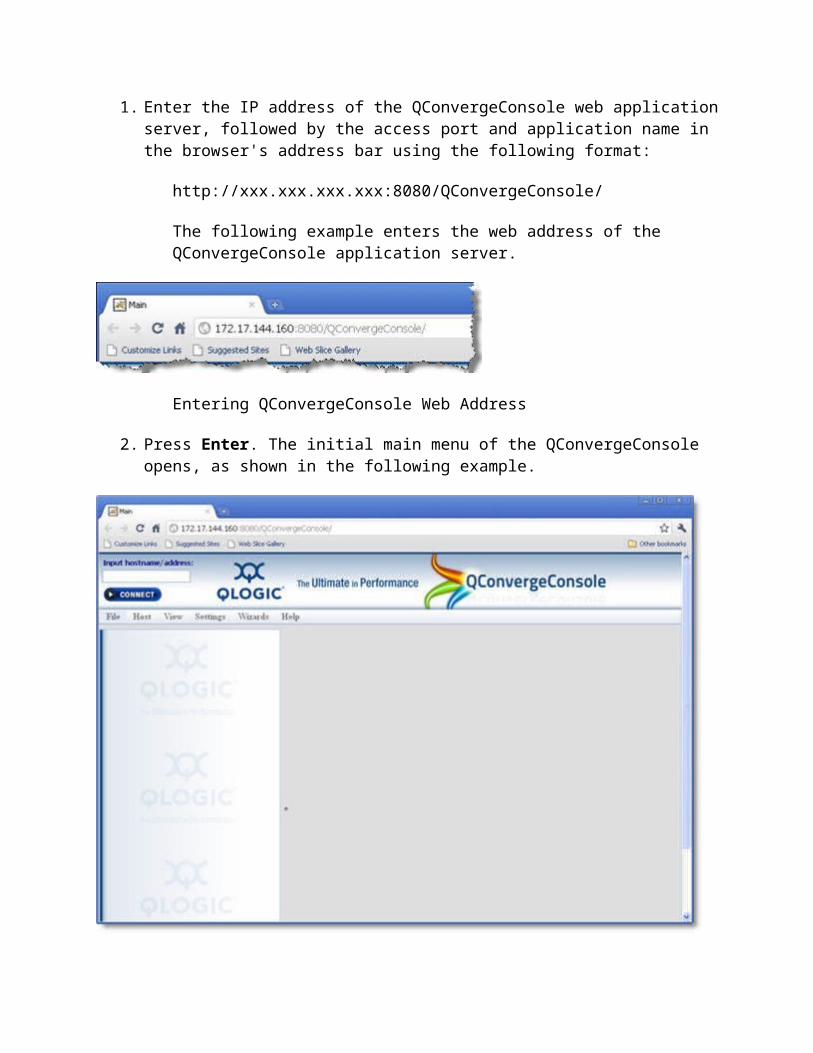
1. Enter the IP address of the QConvergeConsole web application server, followed by the access port and application name in the browser's address bar using the following format:
http://xxx.xxx.xxx.xxx:8080/QConvergeConsole/
The following example enters the web address of the QConvergeConsole application server.

Entering QConvergeConsole Web Address
2. Press Enter. The initial main menu of the QConvergeConsole opens, as shown in the following example.
QConvergeConsole Main Window from a Remote Computer - Unpopulated View
To connect to host servers from the QConvergeConsole main window:
1. Locate the Input hostname/address field in the upper-left corner of the QConvergeConsole screen.
2. Enter the host name or its IP address, as shown in the following example.
Hostname/IP Address Entry Field
3. Click Connect to initiate the connection. If successful, the host and its adapters display in the system tree.
See Also
QConvergeConsole Main Window Exiting the QConvergeConsole QConvergeConsole Overview Browsing Help Contents Viewing QConvergeConsole Software Information Setting QConvergeConsole Security Using Security Check Setting Up Automatic Alarm Notification by E-mail
QConvergeConsole Main Window
The main window gives you access to the features of the QConvergeConsole Unified Adapter Web Management Interface (see Connecting to the QConvergeConsole).
The main window contains a system tree, menu bar, and tabbed pages, as shown in the following example.

QConvergeConsole Main Window Components
System Tree
Located in the left pane of the QConvergeConsole window, the system tree provides expandable/collapsible lists of nodes that represent hosts with their connected adapters, ports, devices, and LUNs. These nodes let you navigate to the management pages for each host's adapters, ports, and devices.
Click next to any tree node to display a list of connected devices. Click next to any tree node to hide a displayed list of connected devices. Click the name or description of any tree node to display tabbed pages with information
and management options related to the selected host, adapter, port, or device in the content pane. Scroll to the bottom of the browser window to see the status bar, which identifies the selected node.
Host Icons and Text
The system tree displays:
Host status - live or offline Host name - host name or IP address Host icons

Online host – The blinking heart on the host icon indicates that the connection between the GUI and the agent is active for this host. An online host can be remote or local.
Indicates a remote host Indicates a local host Offline host – The connection between the QConvergeConsole and the agent is
inactive for this host.
Adapter Icons and Text
The system tree displays:
HBA model (such as, QLA2462, QLE8242, or QLA4060) HBA alias (if assigned) See Displaying Adapter Information. Loop down – The adapter does not have synchronization (cable disconnected, connection
mode set incorrectly, etc.) HBA status – The most severe displays - bad alarm, loop down, warning alarm, or good
(no alarm).
Examples:
HBA QLA2342:Engineering HBA:Warning
HBA QLA2342::Good
FC/CNA HBA Icons Good – No alarm Warning – Warning alarm Loop Down – The adapter does not have synchronization Bad – Bad alarm Offline – Adapter on offline host
Adapter Port Icons and Text
The system tree displays:
HBA port number (Port n) HBA port alias – If assigned Beacon flashing – Flash HBA Port Beacon is enabled (see Finding an Adapter Port) HBA status – The most severe displays are bad alarm, loop down, warning alarm, or
good (no alarm).
Examples:
Port 0:Marketing's HBA port:Good, Beacon Flashing

Port 3::Loop Down
Adapter Port Icons
Good
Warning. Warning alarm
Loop Down
Bad. Bad alarm
Offline. HBA port on offline host
Beacon Flashing, Good
Beacon Flashing, Warning
Loop Down, Beacon Flashing
Beacon Flashing, Bad
Device Icons and Text
The system tree displays the following information about disks, tapes, and SAFTE devices:
Device Type – Disk, tape, or SAFTE (used for enclosure information). Device Port ID – Port ID of the disk, tape, or SAFTE device. Online/Inactive Status – A circled red X on the icon indicates an inactive device (the
device is down, the port on device is down or inactive, or the device is not responding properly to SCSI commands).
Diagnostics enabled/disabled for read/write buffer test – A green check mark on the icon and Diag Enabled in text indicate enabled.
Beacon Flashing – Flash Beacon function is enabled (see Finding a Target).
Examples:
Disk (50-06-0E-83-00-00-2B-21):Online, Diag Disabled
Disk (21-00-00-04-CF-92-7A-B1):Online, Diag Enabled
Tape (10-00-00-04-32-72-06-64):Inactive, Diag Disabled
Device Icons
The disk icons are:
Disk Online, Diag Enabled
Disk Online, Diag Disabled
Disk Inactive, Diag Enabled
The tape icons are:
Tape, Diag Enabled
Tape, Diag Disabled
Tape Inactive, Diag Enabled

Disk Inactive, Diag Disabled
Offline. Disk on offline host
The SAFTE device icons are:
SAFTE device
Offline. SAFTE device on offline host
Tape Inactive, Diag Disabled
Offline. Tape on offline host
LUN Icons and Text
The system tree displays the LUN number (LUN n).
Example:
LUN (0)
LUN Icons
LUN online
LUN on offline host
See Also
Connecting to the QConvergeConsole Exiting the QConvergeConsole GUI QConvergeConsole Overview Browsing Help Contents Viewing QConvergeConsole Software Information
Setting QConvergeConsole Security Using Security Check Setting Up Automatic Alarm Notification by E-mail
Exiting the QConvergeConsole

To exit the QConvergeConsole, point to the File menu on the QConvergeConsole main window and click Exit.
See Also
QConvergeConsole Main Window Getting Help
Getting Help
This section discusses:
Browsing Help Contents Viewing QConvergeConsole Version Details
Browsing Help Contents
You can view the help system for the QConvergeConsole Unified Adapter Web Management Interface at any time using one of the following methods.
To view the help system from the main window:
1. Point to the Help menu on the menu bar and click Browse Contents. The help window displays a navigation pane on the left and a topic pane on the right.
2. From the navigation pane, select one of the following tabs to locate the information you want to display:
1.o Contents – Displays a list of topics organized by task, much like the Table of
Contents in a user's guide. This list also includes book icons that open and close to show and hide topics related to the book title. Click a closed book icon to open it and display its list of topics. Click an opened book icon to close it and hide its topics. Click the title of any book or topic to display its content in the topic pane.
o Index – Provides an alphabetically arranged list of key words. To jump to a keyword, start typing it in the text field. Click any index entry to display a related topic in the topic pane. If a keyword has more than one topic associated with it, a pop-up menu opens, displaying a list of related topics you can select.
o Search – Provides access to all topics contained in the help system using advanced search capabilities. Type one or more keywords in the text field, then

press Enter. The search tool lists all topics that meet your search criteria. Select any topic to display its contents in the topic pane. The search tool accepts Boolean expressions (such as AND, OR, and NOT), as well as nested expressions. It also accepts exact strings entered between quotation marks. It does not support wild cards.
NOTE: The Search and Index tools work best when running the Help system using Internet Explorer or FireFox browsers. Although the help topics display correctly in Chrome or Safari browsers, they do not support the features required to display the Index and Search results.
See Also
Connecting to the QConvergeConsole QConvergeConsole Main Window Exiting the QConvergeConsole QConvergeConsole Overview
Home > Getting Started > Getting Help > Viewing QConvergeConsole Version Details
Viewing QConvergeConsole Version Details
If you need technical assistance with the QConvergeConsole Unified Adapter Web Management Interface, your technician will ask you for the application version number.
To view your QConvergeConsole version:
1. Point to the QConvergeConsole Unified Adapter Web Management Interface main window Help menu and click About. A message window opens, as shown in the following example.
QConvergeConsole Unified Adapter Web Management Interface Version
2. Click OK to return to the QConvergeConsole Unified Adapter Web Management Interface main window.
See Also

Connecting to the QConvergeConsole QConvergeConsole Main Window Exiting the QConvergeConsole QConvergeConsole Overview Browsing Help Contents
Setting QConvergeConsole Security
Setting security on a host server ensures that configuration changes made to its installed adapters require password authorization. The QConvergeConsole prompts for the password when you change the following:
HBA Parameters Flash BIOS HBA driver Port configuration Password (when you want it changed)
You can change the QConvergeConsole access password for any host connected to your system for which you have administrator or root privileges.
NOTE: The default QConvergeConsole access password is located in the readme.txt file. Change this password after installation to ensure that security is not compromised.
To set the application access password for a host:
1. From the system tree, click the host for which you want to set the application access password.
2. Click the Security tab. The Security page displays (see the illustration below). The host name or IP address displays at the top of the tabbed page.

Host Security Page
3. Select the protocol type for ports installed on the host server to which you want to assign passwords:
FC/FCoE - Select this option to set the security on all Fibre Channel and FCoE
ports (QLx2xxx or QLE82xx adapters). iSCSI - Select this option to set the security on all iSCSI ports (QLx40xx or
QLE82xx adapters). Ethernet - Select this option to set the security on all NIC ports (QLE81xx or
QLE82xx adapters).
4. In the Host Access section, do the following to verify that you have administrator or root privileges for the selected host. These are the system login and password you use to access the machine.
a. In the Login field, type the login name that has administrator or root privileges.b. In the Password field, type the login password associated with the login name.
5. In the Application Access section, do the following to modify the QConvergeConsole access password:
a. In the Current Password field, type the current password.b. In the New Password field, type the new password.c. In the Verify New Password field, type the new password again for confirmation.

6. When you finish, click:
1. Apply to update the application access password. Clear Fields to clear the typed entries in the Security tabbed page fields.
See Also
QConvergeConsole Main Window Exiting the QConvergeConsole GUI QConvergeConsole Overview Browsing Help Contents Viewing QConvergeConsole Version Details
Home > Getting Started > Using Security Check
Using Security Check
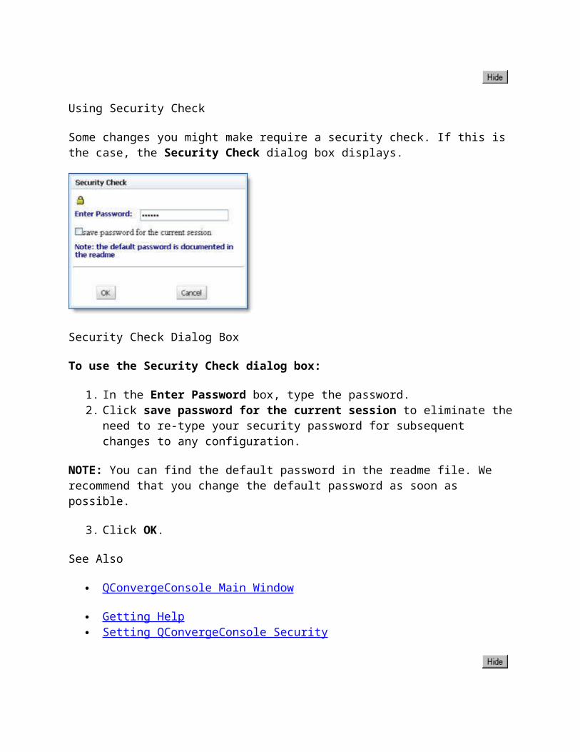
Some changes you might make require a security check. If this is the case, the Security Check dialog box displays.
Security Check Dialog Box
To use the Security Check dialog box:
1. In the Enter Password box, type the password.2. Click save password for the current session to eliminate the need to re-type your
security password for subsequent changes to any configuration.
NOTE: You can find the default password in the readme file. We recommend that you change the default password as soon as possible.

3. Click OK.
See Also
QConvergeConsole Main Window
Getting Help Setting QConvergeConsole Security
Setting Up Automatic Notification by E-mail
You can automatically send notifications with a copy of the current host configuration by e-mail to a distribution list, thus enabling the information to be opened and analyzed from other locations. Notification is available only with SMTP e-mail servers.
To set up automatic notification by e-mail:
1. Point to the QConvergeConsole main window Settings menu and click Email. The Email Settings dialog box opens (see the illustration below).
Email Settings Dialog Box
2. Select the Enable Alarm Notifications over E-mail check box to enable ( ) e-mail notification.
3. Type the host name or an IP address of the SMTP server accessible on the local network in the Server field.
4. Type the login information in the Login field.5. Type the password in the Password field.

6. Click the alarm notification check boxes to toggle their settings to disable ( ) or enable () their selection. Select the notifications that you want to send:
Informational Alarms – Sends messages that require no action. Warning Alarms – Sends warning messages. Bad Alarms– Sends error messages. Unknown Alarms – Sends messages that do not belong in the other message
categories.
7. Enter one or more e-mail addresses (one per line) to be notified in the E-mail Addresses list.
8. Once you finish making your selections, click:
OK to save your modifications and close the E-mail Settings dialog box. Cancel to close the E-mail Settings dialog box without saving the e-mail
notification settings.
See Also
QConvergeConsole Main Window
Getting Help Setting QConvergeConsole Security
Managing Host Connections
This section describes how to connect to a host, create and use a host group, view host information, and set security on adapters installed for a selected host. For details, see the following topics:
Manually Connecting to a Host Connecting to Hosts Using a Host Group Refreshing the Host Configuration Disconnecting from a Host Disconnecting from All Hosts
Manually Connecting to a Host
To manually connect to a host:
1. Locate the Input hostname/address field in the upper-left corner of the QConvergeConsole screen.
2. In the Hostname or IP Address field, enter the host name or its IP address, as shown in the following example.
Hostname / IP Address Entry Field
3. Click Connect to initiate the connection. If successful, the host and its adapters display in the system tree.
See Also
Connecting to Hosts Using a Host Group File Disconnecting from a Host Disconnecting from All Hosts
Connecting to Hosts Using a Host Group
You can connect to a group of host servers using a host group that you previously created. When any host group exists, the QConvergeConsole web server stores a list of the host server names or IP addresses in a text file with the host group name.
For example, after creating a host group named HostGroup1, the application created a text file on the Apache Tomcat web server under this folder path:
C:\Program Files (x86)\Apache Software Foundation\Tomcat 6.0\webapps\QConvergeConsole\hosts\HotGroup1
This section discusses:
Creating a Host Group Using a Host Group to Connect to Hosts
Creating a Host Group

When you create a host group using the QConvergeConsole, it creates a file on the server. The file includes the IP addresses of all host servers included in the saved group.
To save the group of hosts that display in the system tree to a host group file:
1. From the QConvergeConsole main window, point to the Host menu, and then select Group > Save, as shown in the following example.
Selecting Host Save Group
2. Enter a name to assign to the group of hosts, as shown in the following example.
Host Group Save - Entering a File Name
3. Click Save. A message box opens, confirming that the host group was saved successfully.
Successful Host Group Saved Message Box

4. Click OK to close the message box.
See Also
Using a Host Group to Connect to Hosts Manually Connecting to a Host Disconnecting from a Host Disconnecting from All Hosts
Home > Managing Host Connections > Connecting to Hosts Using a Host Group File > Using a Host Group to Connect to Hosts
Using a Host Group to Connect to Hosts
To connect to a group of hosts using a previously created host group:
1. Point to the Host menu on the QConvergeConsole main window and select Group > Open, as shown in the following example. A Host Group Open dialog box opens, displaying a list of saved host groups.
Selecting Open Group from the Host Menu
2. Select the host group name from the Select File Name list, as shown in the following example.

Host Group Open Name Dialog Box
3. Click Open. The system tree populates the hosts in the same order they had been saved as a group. The following illustration shows the system tree populated with hosts connected when the user created the HostGroup1.
QConvergeConsole with Multiple Hosts
See Also
Creating to a Host Group File

Manually Connecting to a Host Disconnecting from a Host Disconnecting from All Hosts
Refreshing the Host Configuration
The host configuration that the QConvergeConsole displays, including the system tree, refreshes automatically based on a default polling interval of 30 seconds.
If you want to refresh the host configuration immediately, for example if the configuration changes, select the host, point to the Host menu, and click Refresh. (See the following illustration.)
Selecting Refresh from the Host Menu
See Also
Using a Host Group to Connect to Hosts Manually Connecting to a Host Disconnecting from a Host Disconnecting from All Hosts
Home > Managing Host Connections > Disconnecting from a Host
Disconnecting from a Host
Disconnecting from a host removes the selected host nodes from the system tree.
To disconnect from a specific host:

1. In the QConvergeConsole system tree, click the host (or adapter, adapter port, device, or LUN connected to the host) that you want to disconnect.
2. Open the Host menu.3. Point to Disconnect and then click Selected Host (see the following illustration).
Disconnecting from the Selected Host
If you want to reconnect to a disconnected host, do so manually (see Manually Connecting to a Host).
See Also
Manually Connecting to a Host Connecting to Hosts Using a Host Group File Disconnecting from All Hosts
Disconnecting from All Hosts
Disconnecting from all hosts removes all host nodes from the system tree.
To disconnect from all hosts:
1. Open the Host menu.2. Point to Disconnect and click All Host(s) (see the following illustration).

Disconnecting from All Hosts
If you want to reconnect to a disconnected host, do so manually (see Manually Connecting to a Host).
See Also
Manually Connecting to a Host Connecting to Hosts Using a Host Group File Disconnecting from a Host
Displaying Host and Adapter Information
The following topics describe how to view general host and adapter information:
Viewing General Host Information Displaying Adapter Information
Viewing General Host Information
To view general information about a host:
1. Click the host node in the QConvergeConsole system tree.2. Click the Information tab. The Information page displays (see the illustration below).

Selecting the Host to Display General Host Information
The Information page displays following information about the selected host:
Hostname – The name or IP address of the connected host server. OS Type – Operating system running on the host server. OS Version – Operating system version. FC/FCoE Agent Version – Version of agent installed on the host to support the Fibre
Channel or FCoE ports on any Fibre Channel or Converged Network Adapters installed on the host server.
ISCSI Agent Version – Version of agent installed on the host to support the iSCSI ports on any iSCSI or Converged Network Adapters installed on the host server.
NIC Agent Version – Version of agent installed on the host to support the NIC ports on any Converged Network Adapters installed on the host server.
See Also
Refreshing the Host Configuration Displaying Adapter Information Managing Fibre Channel and FCoE Adapter Ports Managing iSCSI Ports Managing Ethernet (NIC) Ports

Displaying Adapter Information
To view general information about an adapter connected to a host:
1. In the QConvergeConsole system tree, click the adapter node.2. Click the HBA Info tab. The HBA Info page displays (see the illustration below).
Adapter Port - HBA Info Page
The identifying information displays:
1.o Hostname– Displays the name or IP address of the host connected to the adapter.o HBA Model – Displays the adapter model, which uses the naming convention of
QLx24xx (4Gb), QLx25xx (8Gb), QLE81xx (Converged Network Adapter), QLx40xx (iSCSI Adapter), or QLE82xx (Converged Network Adapter).
The general information displays:
1.o HBA Alias – Displays the symbolic name you can assign to the adapter for
identification purposes. The adapter alias is saved automatically after 5 seconds from the time you stop editing the field; if you press ENTER, the adapter alias is

saved immediately. You may use up to 101 characters, as well as, special characters (. , : ;) when creating an adapter alias.
o Serial Number – Displays the serial number of the adapter.o Driver Version – Displays the version of the adapter driver on the host that
controls the adapter.o Firmware Version – Displays the version of the adapter firmware on the host
that controls the adapter.
See Also
Viewing General Host Information Managing Fibre Channel and FCoE Adapter Ports Managing iSCSI Ports Managing Ethernet (NIC) Ports
Displaying Device Information
The following topics show you how to view information about a device (disk or tape):
Viewing General Target Information Displaying LUN Information Finding a Target
Viewing General Target Information
To view general information about a target or device (disk or tape):
1. Click a target from the QConvergeConsole system tree.2. Click the Device Info tab. The Device Info page displays (see the illustration below).

Device Information Page
The identifying information displays:
Hostname – The name or IP address of the host connected to the adapter. HBA Model – The Fibre Channel or FCoE adapter model. Node Name – World-wide adapter node name. Port Name – World-wide adapter port name. HBA Port – Adapter port number. Port ID – Port ID of the adapter port. MAC Address – Media Access Control (MAC) address hard-coded to the port.
The device information displays:
Product Vendor – Device manufacturer. Product ID – Product ID of the device. Product Revision – Device revision level. Node Name – World-wide node name of the device. Port ID – Port ID of the selected device's port. Port Name – World-wide port name of the selected device's port. Serial Number – The device serial number from page 80 of the VPD data.
See Also
Displaying LUN Information Finding a Targe t

Displaying LUN Information
To view general information about a LUN:
1. In the QConvergeConsole system tree, click the LUN node.2. Click the LUN Info tab. The LUN Info tabbed page for LUN displays (see the
illustration below).
LUN Info Page
The identifying information displays:
1.o Device Product Vendor – Device manufacturer.o Device Product ID – Product ID of the device.o Device Product Rev – Device revision level.o Serial Number – Device serial number from page 80 of the VPD data.o Device Node Name – World-wide node name of the device.o Device Port Name – World-wide port name of the selected device's port.o Device Port ID – Port ID of the selected device's port.
The LUN attributes include:
1.

o Product Vendor – Manufacturer of the LUN.o Product ID – Product ID of the LUN.o LUN – LUN number.o Size – Capacity of the LUN in megabytes or gigabytes.o WWULN – World Wide Unique LUN Name (world wide name of the LUN).o OS LUN Name – Shows the O/S device file path for a given LUN.
See Also
Viewing General Target Information Finding a Target
Finding a Target
You can find the location of a target by the way the hardware flashes. QConvergeConsole allows you to activate a flash beacon on a device. This flash beacon can be toggled on and off.
NOTE: This feature is supported only on 4Gb and 8Gb Fibre Channel adapters. It is not available on iSCSI or Converged Network Adapters.
Flashing a Target's LED
To flash a target's LED:
1. In the QConvergeConsole system tree, click an adapter port.2. Click the Port Info tab. The Port Info page displays. The following example shows the
location of the Beacon (On/Off) toggle button.
Location of Beacon On/Off Toggle Button
3. Click the Beacon On button. Its label changes to Beacon Off, which indicates that clicking it again will turn the beacon off. In the system tree, the adapter port's LED begins to flash, as well as all devices connected to it, as shown in the following example:

Stop Flashing a Target's LED
To stop flashing a target's LED:
1. Right-click the device in the system tree.2. On the shortcut menu, click Flash Beacon. The device's LED stops flashing.
See Also
Viewing General Target Information Displaying LUN Information Finding an Adapter Port
Using Reports
The QConvergeConsole's report facility lets you generate reports, which you can use to view various asset lists. After generating reports, you can view them and save them to a variety of file formats. This provides a hard copy record of your system assets. The report facility gives you eight report options:
Device centric SAN report – Generates a device list of all SAN assets: adapters, devices, and LUNs.
Flash version asset by host and adapter report – Generates an adapter flash asset list of all version attributes grouped by host name and adapter.
Adapter asset by DataRate report – Generates an adapter asset list of all adapter attributes grouped by adapter data rate.
Adapter asset by host report – Generates an adapter asset list of all adapter attributes grouped by host name.
Adapter asset by type report – Generates an adapter asset list of all adapter attributes grouped by adapter type.
Host asset report – Generates a host asset list of all host names, operating system types, and OS versions.
LUN asset by attached adapter report – Generates a LUN asset list of all adapter attributes grouped by attachment.
Transceiver vendor asset by adapter report – Generates a transceiver asset list of all attributes grouped by adapter.
The generated report opens as a PDF document, which you can save on your local system in any formats provided in Acrobat's drop-down list of file types, such as:
PDF RTF HTML XML

NOTE: The software required to view the available report file formats is not packaged with the QConvergeConsole application.
See Also
Generating Reports Viewing Reports
Generating Reports
QConvergeConsole allows you to create reports that describe SAN assets, host names, adapter flash assets, adapter assets, LUN assets, and transceiver assets.
To generate reports:
1. Point to the View menu and click Generate Reports. The Generate Reports dialog box appears, as shown in the following example.
Generate Reports Dialog Box
2. Click on one of the following:
Device centric SAN report – Generates a device list of all SAN assets: adapters, devices, and LUNs.
Flash version asset by host and adapter report – Generates an adapter flash asset list of all version attributes grouped by host name and adapter.
Adapter asset by DataRate report – Generates an adapter asset list of all adapter attributes grouped by adapter data rate.

Adapter asset by host report – Generates an adapter asset list of all adapter attributes grouped by host name.
Adapter asset by type report – Generates an adapter asset list of all adapter attributes grouped by adapter type.
Host asset report – Generates n host asset list of all host names, operating system types, and OS versions.
LUN asset by attached adapter report – Generates a LUN asset list of all adapter attributes grouped by attachment.
Transceiver vendor asset by adapter report – Generates a transceiver asset list of all attributes grouped by adapter.
3. After selecting the report type click:
1.o Generate to generate and display the report.o Cancel to close the Generate Reports dialog box without creating a report.

Generated Report Sample
4. After reviewing the report, you can save it in any of the formats provided in your Adobe Acrobat Save As file type drop-down list. For example:
1.o PDFo RTFo HTMLo XML

See Also
Reports Viewing Reports
Viewing Reports
Once you generate the specified report, it opens as a PDF document in your installed Adobe Acrobat application. Use the tools provided in your Adobe Acrobat application to view or print the report as desired. You can also save the report in to a variety of file formats allowing, which provides a hard copy record of your system assets.

Generated Report Sample
See Also
Reports Generating Reports
Managing Fibre Channel and FCoE Adapter Ports

Selecting a Fibre Channel or FCoE port in the QConvergeConsole's system tree displays a set of information and configuration pages in the content pane. While some of these pages display information regarding the selected port, others let you modify port and adapter configuration settings.
Except where indicated, parameters described in the topic examples exist on all Fibre Channel and FCoE ports, which reside on either a Fibre Channel (QLx23xx, QLx24xx, QLx25xx) or Converged Network Adapter (QLE81xx and QLE82xx).
The following topics describe how to use the adapter port information and configuration pages:
Viewing General Adapter Port Information Finding an Adapter Port Viewing General Adapter Port VPD Information Viewing and Updating Adapter Port Monitoring Updating the Fibre Channel or Converged Network Adapter Using the Adapter's Advanced Utilities Using Virtualization (NPIV) Performing Diagnostics
Viewing General Adapter Port Information
To view general information about an adapter port:
1. In the QConvergeConsole system tree, click an adapter port.2. Click the Port Info tab. The Port Info page displays (see the illustrations below).

1. Selecting FCoE Port to Display Port Info Page

1. Selecting Fibre Channel Port to Display Port Info Page
Located at the top of the page, the identifying information shows:
Hostname – The name or IP address of the host connected to the adapter. HBA Model – The Fibre Channel or FCoE adapter model. Node Name – World-wide adapter node name. Port Name – World-wide adapter port name. HBA Port – Adapter port number. Port ID – Port ID of the adapter port. MAC Address – Media Access Control (MAC) address hard-coded to the port. (FCoE
ports only)
The General Information section displays the following information:
Port Alias – Symbolic name you can assign to the Fibre Channel Adapter port for identification purposes. The port alias is saved automatically after 5 seconds from the time you stop editing the field; if you press ENTER, the port alias is saved immediately. You may use up to 101 characters, as well as, special characters (. , : ;) when creating an Fibre Channel Adapter port alias.

Serial Number – Serial number of the Fibre Channel Adapter. BIOS Version – BIOS version on the Fibre Channel Adapter port (Windows XP
Professional, Windows 2000, Windows Server 2003, Windows Vista, Windows Server 2008, Linux, NetWare, and Solaris x86).
Actual Connection Mode – The actual connection mode (unknown, loop, or point-to-point) of the Fibre Channel Adapter port.
Actual Data Rate – The actual Fibre Channel Adapter port data rate (unknown, 1 Gbps, 2 Gbps, 4Gbps, or 8 Gbps).
Driver Version – Fibre Channel Adapter driver version on the host that controls the Fibre Channel Adapter.
Firmware Version – Fibre Channel Adapter firmware version on the host that controls the Fibre Channel Adapter.
QLdirect Driver Version – Fibre Channel Adapter QLdirect driver version on the host that controls the Fibre Channel Adapter.
NOTE: QLdirect is available only on Linux platforms.
OS Instance – The operating system number from which the Fibre Channel Adapter can be accessed (Solaris SPARC only).
Fibre Channel Adapter Instance – The API Instance number from which the Fibre Channel Adapter can be accessed.
The Flash Information section displays the following information (4Gb or greater Fibre Channel Adapters only):
BIOS Version – Current BIOS version. FCode Version – FCode version on the Fibre Channel Adapter port (Solaris SPARC or
Macintosh). EFI Version – Current EFI version. Firmware Version – Current Flash firmware version.
The PCIe General Info section displays the following firmware-driven information:
Max Bus Width – Maximum bus width. Max Bus Speed – Maximum bus speed per lane. Negotiated Width – The link width, which the firmware updates after a link negotiation. Negotiated Speed – The link speed per lane, which the firmware updates after a link
negotiation.
See Also
Viewing Fibre Channel and FCoE Port VPD Information Viewing or Modifying Adapter Parameters Setting Advanced Adapter Parameters Selecting Boot Device Restoring Default Adapter Parameter from a File

Updating Flash from a File Updating the Adapter Driver
Finding an Adapter Port
You can find the location of a port by the way the hardware flashes. QConvergeConsole allows you to activate a flash beacon on a port. You can toggle this flash beacon on and off.
NOTE: This feature is supported only on 4Gb and 8Gb Fibre Channel adapters. It is not available on iSCSI or Converged Network Adapters.
Flashing a Port's LED
To flash the adapter port LED:
1. In the QConvergeConsole system tree, click an adapter port.2. Click the Port Info tab. The Port Info page displays. The following example shows the
location of the Beacon (On/Off) toggle button.
Location of Beacon On/Off Toggle Button
3. Click the Beacon On button. Its label changes to Beacon Off, which indicates that clicking it again will turn the beacon off. In the system tree, the adapter port's LED begins to flash, as shown in the following example:
Stop Flashing a Port's LED

To stop the LED from flashing:
1. In the QConvergeConsole system tree, click an adapter port.2. Click the Port Info tab. The Port Info page displays. 3. Click the Beacon Off button. Its label changes to Beacon On, which indicates that
clicking it again will turn the beacon off.
See Also
Viewing General Adapter Port Information Viewing General Adapter Port VPD Information Viewing and Updating Adapter Port Monitoring Updating the Fibre Channel or Converged Network Adapter Using the Adapter's Advanced Utilities Using Virtualization (NPIV) Performing Diagnostics
Viewing Fibre Channel and FCoE Port VPD Information
NOTE: The VPD tabbed page is absent for MAC operating systems.
To view VPD (Vital Product Data) information about an adapter port:
1. Click a 4Gb, 8Gb, or FCoE adapter port from the QConvergeConsole system tree.2. Click the VPD tab. The VPD page displays (see the illustration below).

4Gb or 8Gb Adapter Port VPD Page
FCoE Adapter Port VPD Page
Located at the top of the page, the identifying information shows:
Hostname – The name or IP address of the host connected to the adapter. HBA Model – The Fibre Channel or FCoE adapter model. Node Name – World-wide adapter node name. Port Name – World-wide adapter port name. HBA Port – Adapter port number. Port ID – Port ID of the adapter port.

MAC Address – Media Access Control (MAC) address hard-coded to the port. (FCoE ports only)
The general information displays:
Product Identifier – Product identifier of the adapter. Part Number – Part number of the adapter. Serial Number – Serial number of the adapter. Misc. Information – Miscellaneous information of the 4Gb or 8Gb adapter port. Manufacturing ID – Manufacturing ID of the 4Gb or 8Gb adapter. EFI Driver Version – EFI driver version on the 4Gb or 8Gb adapter port. Firmware Version – Version of the 4Gb or 8Gb adapter firmware on the host that
controls the adapter. BIOS Version – BIOS version on the 4Gb or 8Gb adapter port. FCode Version – FCode version on the 4Gb or 8Gb adapter port. Engineering Date Code – Date code engineering uses to identify release information on
an FCoE adapter port. Flash Image Version – Multiflash image version on an FCoE adapter port.
See Also
Viewing General Adapter Port Information Viewing or Modifying Port Parameters Setting Advanced Adapter Parameters Selecting Boot Device Restoring Default Adapter Parameter from a File Updating Flash from a File Updating the Adapter Driver
Viewing and Updating Adapter Port Monitoring
You can access the adapter port monitoring facility from the Monitoring page of any Fibre Channel or FCoE port. Adapter port monitoring allows you to monitor the following port parameters on an operating adapter port in real-time:
BPS Device Errors HBA Port Error I/O Count IOPS Reset

For details, see the following topics:
Viewing Adapter Port Monitoring Setting the Sampling Rate for Adapter Port Monitoring
Viewing Adapter Port Monitoring
NOTE: If you are using the IOCTL module with inbox drivers in Red Hat 4.0, adapter port monitoring is disabled. Adapter port monitoring is also disabled if you are using sysfs supported inbox drivers with Red Hat 5.0 or SLES 10.0.
The adapter port monitoring facility displays each parameter value in a table.
To view statistical information about an adapter port:
1. Click on a Fibre Channel or FCoE adapter port from the QConvergeConsole system tree.2. Click the Monitoring tab. The Monitoring page appears, as shown in the following
example.
Adapter Port Monitoring Page
The identifying information displays:
Hostname – The name or IP address of the host connected to the adapter. Node Name – World-wide adapter node name. HBA Port – Adapter port number.

HBA Model – Adapter model number. Port Name – World-wide adapter port name. Port ID – Port ID of the adapter port.
The statistical information displays:
BPS – Number of bytes processed by the adapter port per second. Device Errors – Number of device errors reported by the adapter's driver. HBA Port Errors – Number of errors for this adapter port reported by the adapter's
driver. I/O Count – Total number of I/Os reported by the adapter's driver. IOPS – Number of I/Os processed by the adapter port per second. Reset – Number of LIP resets reported by the adapter's driver.
See Also
Setting the Sampling Rate for Adapter Port Monitoring
Home > Managing Fibre Channel and FCoE Adapters and Ports > Viewing and Updating Adapter Port Monitoring > Setting the Sampling Rate for Adapter Port Monitoring
Setting the Sampling Rate for HBA Port Monitoring
You can set the adapter port monitor to automatically update at a given rate, between 5 and 30 seconds, by setting the statistics sampling rate.
NOTE: The faster the statistics sampling rate, the more quickly the QConvergeConsole receives data from the host. However, faster statistics sampling rates consume more of your system's CPU and network resources and slows the system.
To set the statistics sampling rate for adapter port monitoring:
1. Click on a Fibre Channel or FCoE adapter port from the QConvergeConsole system tree.2. Click the Monitoring tab. The Monitoring page appears, as shown in the following
example.

Adapter Port Statistics Page
3. Click Set Rate in the Monitoring page. The Set Rate dialog box appears, as shown in the following example.
Set Rate Dialog Box
4. In the Set Rate field, use the up and down arrow keys to scroll to the desired sampling rate interval. The smaller the number you choose, the faster the sampling rate.The range is 5 to 30 seconds. The default is 5 seconds.
5. Click OK to set the sampling rate. 6. Click Start to commence collecting data at the statistics sampling rate. When you finish
collecting data, click Stop to end the data collecting session.
See Also
Viewing Adapter Port Monitoring
Home > Managing Fibre Channel and FCoE Adapters and Ports > Updating the Fibre Channel or Converged Network Adapter

Updating the Fibre Channel or Converged Network Adapter
The QConvergeConsole lets you update a Fibre Channel or Converged Network Adapter's nonvolatile RAM (adapter parameters) settings, Flash, and driver (Windows only). The following topics describe these update and save operations:
Viewing or Modifying Port Parameters Updating Flash from a File Updating the Adapter Driver Using the SAN Flash Update Wizard Using the SAN Parameters File Update Wizard Restoring Default Adapter Parameter from a File
NOTE: Flash BIOS applies only to Windows XP Professional, Windows 2000, Windows Server 2003, Windows Vista, Windows Server 2008, Red Hat/SuSE Linux, and Solaris x86 systems. FCode applies to Solaris SPARC, Linux ppc64, and MAC pcc (4Gb or greater Fibre Channel adapters only) systems. EFI applies to IA64, Linux IA64 and MAC Intel (4Gb or greater Fibre Channel adapters only). Refer to the appropriate QLA2xxx Fibre Channel adapter software installation guide for information about adapter configuration settings.
Modifying Port Parameters
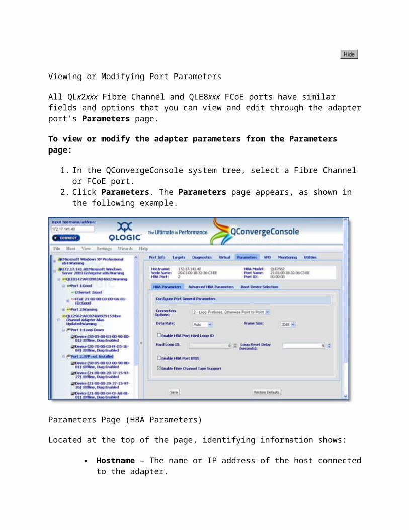
Viewing or Modifying Port Parameters
All QLx2xxx Fibre Channel and QLE8xxx FCoE ports have similar fields and options that you can view and edit through the adapter port's Parameters page.
To view or modify the adapter parameters from the Parameters page:
1. In the QConvergeConsole system tree, select a Fibre Channel or FCoE port.2. Click Parameters. The Parameters page appears, as shown in the following example.

Parameters Page (HBA Parameters)
Located at the top of the page, identifying information shows:
Hostname – The name or IP address of the host connected to the adapter. HBA Model – The Fibre Channel or FCoE adapter model. Node Name – World-wide adapter node name. Port Name – World-wide adapter port name. HBA Port – Adapter port number. Port ID – Port ID of the adapter port. MAC Address – Media Access Control (MAC) address hard-coded to the port.
(FCoE ports only)
3. Select the desired adapter parameters using the sub-tabs described in the following topics: HBA Parameters Advanced HBA Parameters Boot Device Selection
4. When you are finished making changes, click Save to save any changes to the adapter advanced parameters. The Save HBA Parameter Changes dialog box may display. Click Yes to save the changes.
After clicking Yes, the Security Check dialog box may display. In the Enter Password box, type the password. Click OK. See Security Check.

Any previously saved configuration for the current adapter is overwritten.
Restoring Factory Default Settings
To restore parameters to their default factory settings, click Restore Defaults. The software reads the default adapter parameters settings from the Flash BIOS image. If the software cannot read the BIOS image, then an error message displays and the operation stops. If the software can read BIOS, it immediately updates the current adapter parameters with the defaults.
NOTE: Restore Defaults applies to 4Gb or greater adapters only. If this feature fails to restore the default settings, see Restoring Default Adapter Parameter from a File.
See Also
Viewing General Adapter Port Information Viewing General Adapter Port VPD Information Restoring Default Adapter Parameter from a File Updating Flash from a File Updating the Adapter Driver
Home > Managing Fibre Channel and FCoE Adapters and Ports > Updating the Fibre Channel or Converged Network Adapter > Viewing or Modifying Port Parameters > HBA Parameters
HBA Parameters
This topic describes the fields and options available on the HBA Parameters sub-tab, located on the Parameters page for any selected Fibre Channel or FCoE port. The following example illustrates the HBA Parameters sub-tab.

HBA Parameters Sub-tab - Fibre Channel or FCoE Port
The following paragraphs describe each of these parameters.
NOTE: Only Enable HBA Port BIOS is supported on QLA2xx and QLE2xx adapters.
Connection Options – This setting defines the type of connection (loop or point-to-point) or connection preference. The FCoE port default setting is Point to Point Only. For the QLA22xx adapter, the default is 3 - Point-to-Point, Otherwise Loop. For the QLA23xx adapter, the default is 2 - Loop Preferred, Otherwise Point-to-Point.
Data Rate – This setting determines the adapter port data rate. The FCoE ports can run at 10 Gbps. When this setting is 8 Gbps, the 25xx adapter port runs at 8 Gbps. When this setting is 4 Gbps, the 24xx adapter port runs at 4 Gbps. When this setting is 2 Gbps, the 23xx adapter port runs at 2 Gbps. When this setting is Auto, QConvergeConsole determines what rate your system can accommodate and sets the rate accordingly. The default is Auto.
NOTE: The 1 Gb data rate selection is not available for 8Gb adapters or FCoE ports.
Frame Size – This setting specifies the maximum frame length supported by the QLA2xxx adapter. For the QLA22xx adapter, the default size is 1024. If using F-Port (point-to-point) connections, change this setting to 2048 for maximum performance.
The default size is 2048 for 4Gb or 8Gb Fibre Channel or FCoE ports, which provides maximum performance for F-Port (point-to-point) connections.
Enable HBA Port Hard Loop ID – This setting forces the adapter to attempt to use the ID specified in the Hard Loop ID setting. The default is disabled.
Hard Loop ID – If the Enable HBA Port Hard Loop ID setting is enabled, the adapter attempts to use the ID specified in this setting. The default ID is 0.
Loop Reset Delay – After resetting the loop, the firmware refrains from initiating any loop activity for the number of seconds specified in this setting. The default is 5 seconds.
Enable HBA Port BIOS – When this setting is disabled, the ROM BIOS on the adapter is disabled, freeing space in upper memory. This setting must be enabled if you are booting from a Fibre Channel hard disk attached to the adapter. The default is disabled.
Enable Fibre Channel Tape Support – This setting enables FCP-2 recovery. The default is disabled.
See Also
Viewing or Modifying Port Parameters Advanced Adapter Parameters Boot Device Selection

Home > Managing Fibre Channel and FCoE Adapters and Ports > Updating the Fibre Channel or Converged Network Adapter > Viewing or Modifying Port Parameters > Advanced HBA
Parameters
Advanced HBA Parameters
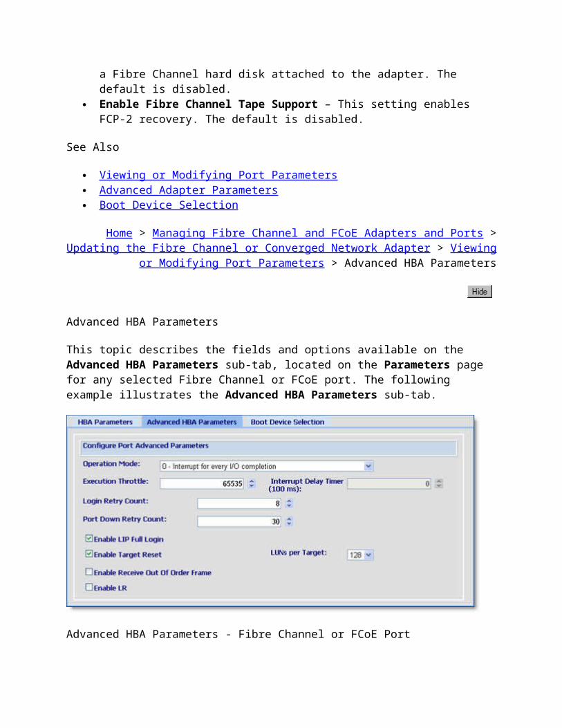
This topic describes the fields and options available on the Advanced HBA Parameters sub-tab, located on the Parameters page for any selected Fibre Channel or FCoE port. The following example illustrates the Advanced HBA Parameters sub-tab.
Advanced HBA Parameters - Fibre Channel or FCoE Port
The following paragraphs describe each of these parameters.
Operation Mode – Specifies the reduced interrupt operation (RIO) modes, if supported by the software driver. RIO modes allow posting multiple command completions in a single interrupt. The default is 0 - Interrupt for every I/O completion. When this setting is 0, the Interrupt Delay Timer setting is disabled. This setting does not apply to the QLA22xx adapter.
Execution Throttle – Specifies the maximum number of commands executing on any one port. When a port's execution throttle is reached, no new commands are executed until the current command finishes executing. The valid options for this setting are 1-65535. The default is 65535.
Interrupt Delay Timer – Contains the value (in 100-microsecond increments) used by a timer to set the wait time between accessing (DMA) a set of handles and generating an interrupt. The default is 0. This setting is enabled only when the Operation Mode setting

is 5 or 6. When the Operation Mode setting is 0, this setting is disabled. This setting does not apply to the QLA22xx adapter.
Login Retry Count – Specifies the number of times the software tries to log in to a device. The default is 8 retries.
Port Down Retry Count – Specifies the number of times the software retries a command to a port returning port down status. The default is 30 retries.
Enable LIP Full Login – Instructs the ISP chip to re-login to all ports after any loop initialization process (LIP). The default is enabled.
Enable Target Reset – Enables the drivers to issue a Target Reset command to all devices on the loop when a SCSI Bus Reset command is issued. The default is enabled.
LUNs per Target – Specifies the number of LUNs per target. Multiple LUN support is typically for RAID boxes that use LUNs to map drives. The default is 128. If you do not need multiple LUN support, set the number of LUNs to 0.
Enable Receive Out Of Order Frame (4Gb or greater adapters only) – Reassembles out-of-order frames as they are received, minimizing network congestion by eliminating the re-transmission of frames and exchanges.
Enable LR – Determines the type of LIP reset used when the operating system initiates a bus reset routine. When this setting is enabled, the driver initiates a global LIP reset to clear the target device reservations. When this setting is disabled, the driver initiates a global LIP reset with full login. The default is disabled.
NOTE: You do not need to reboot the adapter for the changes to take effect.
See Also
Viewing or Modifying Port Parameters HBA Parameters Boot Device Selection
Home > Managing Fibre Channel and FCoE Adapters and Ports > Updating the Fibre Channel or Converged Network Adapter > Viewing or Modifying Port Parameters > Boot Device
Selection
Boot Device Selection
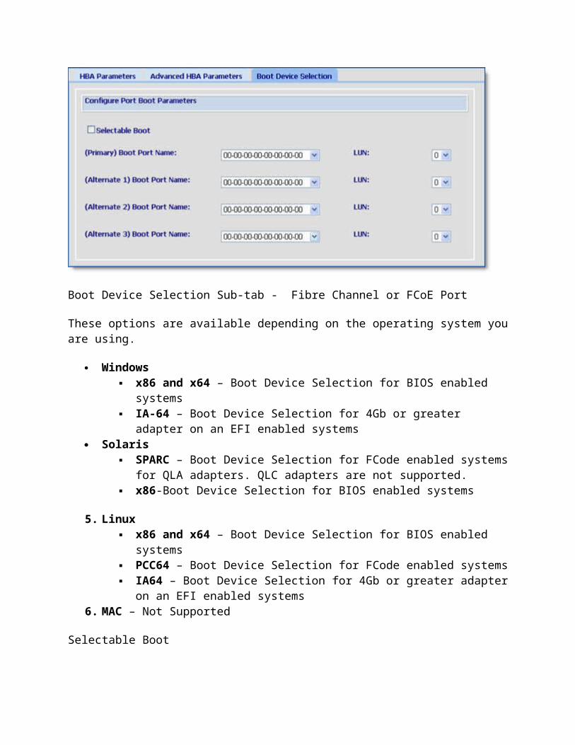
This topic describes the fields and options available on the Boot Device Selection sub-tab, located on the Parameters page for any selected Fibre Channel or FCoE port. The following example illustrates the Boot Device Selection sub-tab.
NOTES:• Currently this feature is disabled on Macintosh.• Boot device selection cannot be set for multiple adapter ports (only the HBA Parameters and Advanced HBA Parameters options apply to multiple adapter ports).

Boot Device Selection Sub-tab - Fibre Channel or FCoE Port
These options are available depending on the operating system you are using.
Windows x86 and x64 – Boot Device Selection for BIOS enabled systems IA-64 – Boot Device Selection for 4Gb or greater adapter on an EFI enabled
systems Solaris
SPARC – Boot Device Selection for FCode enabled systems for QLA adapters. QLC adapters are not supported.
x86-Boot Device Selection for BIOS enabled systems
5. Linux x86 and x64 – Boot Device Selection for BIOS enabled systems PCC64 – Boot Device Selection for FCode enabled systems IA64 – Boot Device Selection for 4Gb or greater adapter on an EFI enabled
systems6. MAC – Not Supported
Selectable Boot
Use selectable boot if you want the operating system to boot from the first target the BIOS finds.
NOTE: This option is not available on Solaris SPARC or Macintosh.
To use selectable boot:
1. Click the Selectable Boot check box.

2. From the (Primary) Boot Port Name list, click on the default setting: 00-00-00-00-00-00-00-00.
NOTE: Selecting a target other than the default setting from the (Primary) Boot Port Name list overrides the Selectable Boot setting. The target is selected using the primary boot port name.
3. In the HBA Parameters section, click Enable HBA Port BIOS (see HBA Parameters).4. When you are finished making changes, click Save to save any changes to the boot drive
parameters. The Save HBA Parameter Changes dialog box may display. Click Yes to save the changes.
After clicking Yes, the Security Check dialog box may display. In the Enter Password box, type the password. Click OK. See Security Check.
Any previously saved configuration for the current adapter is overwritten.
Primary Boot Port Name
Use the primary boot port name if you want the operating system to boot from a particular target.
To use the primary boot port name:
1. Click the target from the (Primary) Boot Port Name list. The operating system boots from that target.
In Windows XP Professional, Windows 2000, Windows Server 2003, Windows Vista, and Windows Server 2008, when "00-00.......00-00" is selected from the Primary Boot Port Name list, the operating system boots from the first target it finds with LUN 0.
In Solaris SPARC/x86 or Macintosh, when "00-00.......00-00" is selected from the Primary Boot Port Name list, all boot device information is cleared.
2. From the LUN list, click the LUN of the target from which you want to boot. This option is used with the (Primary) Boot Port Name to verify the boot device.
o In Macintosh, view the target ID. The Target ID read-only field designates the target ID of the device from which the operating system boots.
o In Solaris SPARC click an ID from the Target ID list.
Target IDs can be assigned to configured ports. Valid target ID values are in the range 0-2047. The IDs are validated before they are saved. Duplicate target IDs are not allowed.When you set a target ID for a visible path in Solaris SPARC, the same target ID is not set for both hidden and configured paths.The target ID cannot be modified if the device has been selected as a boot device.
Once persistent binding information for the targets is saved, the ports retain the assigned target IDs across reboots.
3. When you are finished making changes, click Save to save any changes to the boot drive parameters. The Save HBA Parameter Changes dialog box may display. Click Yes to save the changes. After clicking Yes, the Security Check dialog box may display. In the Enter Password box, type the password. Click OK. See Security Check.Any previously saved configuration for the current adapter is overwritten.
Alternate Boot Port Name
Use the alternate boot port name if you want the operating system to boot from that target. You must first select a primary boot port name. After selecting the primary boot port name, you can select up to three alternate boot port names.
To select the alternate boot port name:
1. Click the primary boot port name (see Primary Boot Port Name procedure).2. Click the alternate boot port name by selecting a port name from the Alternate Boot
Port Name list.3. From the LUN list, click the LUN of the target from which you want to boot. This option
is used with the alternate boot port name to verify the boot device.o In Macintosh, view the target ID. The Target ID read-only field designates the
target ID of the device from which the operating system bootso In Solaris SPARC click an ID from the Target ID list.
Target IDs can be assigned to configured ports. Valid target ID values are in the range 0-2047. The IDs are validated before they are saved. Duplicate target IDs are not allowed.When you set a target ID for a visible path in Solaris SPARC, the same target ID is not set for both hidden and configured paths.The target ID cannot be modified if the device has been selected as a boot device.Once persistent binding information for the targets is saved, the ports retain the assigned target IDs across reboots.
4. When you are finished making changes, click Save to save any changes to the boot drive parameters. The Save HBA Parameter Changes dialog box may display. Click Yes to save the changes. After clicking Yes, the Security Check dialog box may display. In the Enter Password box, type the password. Click OK. See Security Check.Any previously saved configuration for the current adapter is overwritten.
NOTE: When performing boot device selection and target persistent binding on Solaris SPARC, if a target device is selected as the boot device, the Bind check box and the Target ID field in the Target Persistent Binding page are disabled for the corresponding target.In addition, the Bind check box is checked, indicating that the target is already persistently
bound with the given target ID (in the adapter parameters). As a result, the corresponding target ID is taken; you cannot assign the same target ID to another target on the same adapter.
See Also
Viewing or Modifying Port Parameters HBA Parameters Advanced HBA Parameters
Home > Managing Fibre Channel and FCoE Adapters and Ports > Updating the Fibre Channel or Converged Network Adapter > Updating Flash from a File
Updating Flash from a File
CAUTION! Using the wrong file can render the adapter and the OS unusable. Be sure to use the correct file.
NOTES:
• Only Solaris SPARC and Linux PCC systems use Flash FCode.
• The Utilities tab is absent from Netware systems using 4Gb or greater adapters.
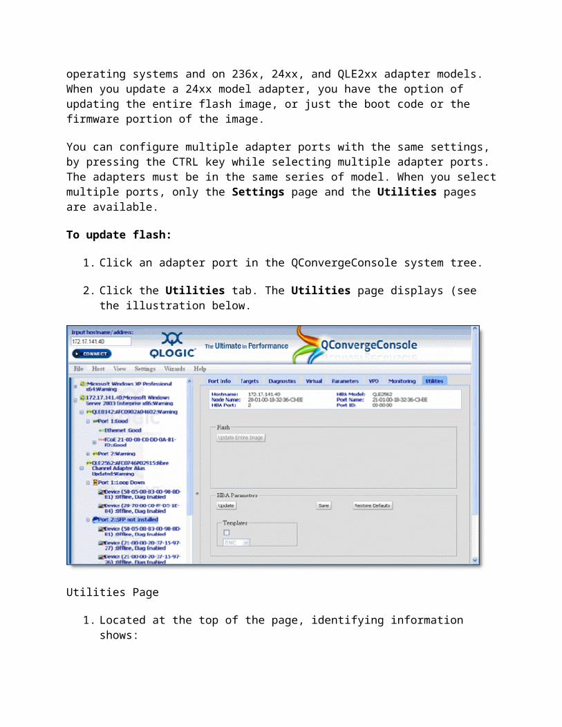
You can update the flash on an adapter from a file. The QConvergeConsole update flash feature is available on all operating systems and on 236x, 24xx, and QLE2xx adapter models. When you update a 24xx model adapter, you have the option of updating the entire flash image, or just the boot code or the firmware portion of the image.
You can configure multiple adapter ports with the same settings, by pressing the CTRL key while selecting multiple adapter ports. The adapters must be in the same series of model. When you select multiple ports, only the Settings page and the Utilities pages are available.
To update flash:
1. Click an adapter port in the QConvergeConsole system tree.
2. Click the Utilities tab. The Utilities page displays (see the illustration below.

Utilities Page
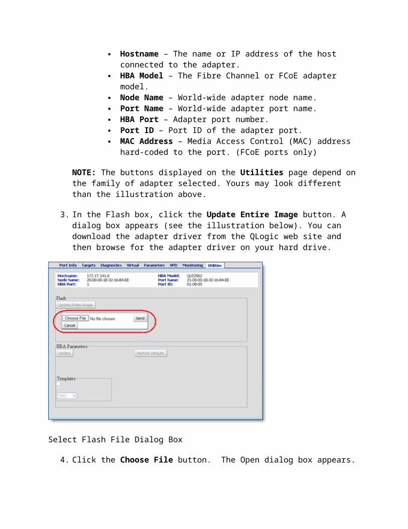
1. Located at the top of the page, identifying information shows: Hostname – The name or IP address of the host connected to the adapter. HBA Model – The Fibre Channel or FCoE adapter model. Node Name – World-wide adapter node name. Port Name – World-wide adapter port name. HBA Port – Adapter port number. Port ID – Port ID of the adapter port. MAC Address – Media Access Control (MAC) address hard-coded to the
port. (FCoE ports only)
NOTE: The buttons displayed on the Utilities page depend on the family of adapter selected. Yours may look different than the illustration above.
3. In the Flash box, click the Update Entire Image button. A dialog box appears (see the illustration below). You can download the adapter driver from the QLogic web site and then browse for the adapter driver on your hard drive.

Select Flash File Dialog Box
4. Click the Choose File button. The Open dialog box appears.5. Navigate to and click on the file from which to update, then click Open. Make sure you
select the correct file. It must end with a .bin extension. Firmware files are unique to each adapter model.
NOTE: The Flash file must end with a .bin extension. Note that Flash files are unique to each adapter model.
6. If you select a file that is an unacceptable Flash file for the adapter, the unacceptable Flash data file message displays. Re-select a valid file and click OK. The Security Check dialog box appears.
7. In the Enter Password box, type the password., and then click OK. See Security Check. The page appears dimmed during the update.
8. When complete, the flash update complete message appears.
See Also
Viewing General Adapter Port Information Viewing General Adapter Port VPD Information Viewing or Modifying Port Parameters Setting Advanced Adapter Parameters Selecting Boot Device Restoring Default Adapter Parameter from a File Updating the Adapter Driver
Home > Managing Fibre Channel and FCoE Adapters and Ports > Updating the Fibre Channel or Converged Network Adapter > Updating the Adapter Driver
Updating the Adapter Driver
NOTES:
• For Solaris operating systems:■ Do not use QLA driver versions 4.03 or lower.■ No driver update support on QLC attached adapters.
• For Linux operating systems:■ A warning appears when going from an Inbox driver to a standard driver.■ Use the Linux driver installer package (NOT the driver package) to install the driver.■ No driver update permitted on VMware.
• All QLA2xxx/QLA24xx/QLE24xx/QLE25xx Fibre Channel and QLE82xx/QLx81xx/QMI81xx FCoE adapters on the same host use different drivers.
You can get the adapter driver from the QLogic Web site or service personnel.
To update the adapter driver:
NOTE: All 23xx/24xx/2xx/25xx Fibre Channel adapters on the host use the same driver. All QLA22xx Fibre Channel adapters on the host use a different driver.
1. Click an adapter port in the QConvergeConsole system tree.
NOTE: You can select only one adapter from the system tree; you cannot select multiple adapters when updating the adapter driver.
2. Click the Utilities tab. The Utilities page displays (see the illustration below).

Utilities Page for Fibre Channel and FCoE Adapter Ports
Located at the top of the page, identifying information shows:
Hostname – The name or IP address of the host connected to the adapter. HBA Model – The Fibre Channel or FCoE adapter model. Node Name – World-wide adapter node name. Port Name – World-wide adapter port name. HBA Port – Adapter port number. Port ID – Port ID of the adapter port. MAC Address – Media Access Control (MAC) address hard-coded to the port.
(FCoE ports only)
NOTE: The buttons displayed on the Utilities tabbed page depend on the family of adapter selected. Yours may look different than the illustration above.
3. In the HBA Parameters box, click the Update button. A dialog box appears. You can download the adapter driver from the QLogic web site and then browse for the adapter driver on your hard drive.

Select Driver Dialog Box
4. Click the Choose File button. The Open dialog box appears.5. Navigate to and select the driver file, then click Open to proceed. The driver update
version check message shows the driver version to be installed and the current driver version.
6. Click Yes to install the new driver. The Security Check dialog box appears. 7. In the Enter Password box, type the password, and then click OK.
No matter which method you use to update the adapter driver, when the method is complete the driver update complete message appears. Click OK. If prompted, reboot the system.
TIP: On a Linux operating system, the following message may appear:
Unable to update driver. Module qla2xxx is in use, installer can not proceed.
If this happens, ensure the following conditions:
• No multiple qlremote processes are running• SCLI is not running• No I/Os are running• When trying to update the driver remotely from another system, make sure you are not running locally.
See Also
Viewing General Adapter Port Information Viewing General Adapter Port VPD Information
Viewing or Modifying Port Parameters Setting Advanced Adapter Parameters Selecting Boot Device Restoring Default Adapter Parameter from a File Updating Flash from a File
Home > Managing Fibre Channel and FCoE Adapters and Ports > Updating the Fibre Channel or Converged Network Adapter > Using the SAN Flash Update Wizard
Using the SAN Flash Update Wizard
The SAN Flash Update Wizard helps you update the flash across multiple hosts in your SAN.
To start the SAN Flash Update Wizard from the QConvergeConsole main window, point to the Wizards menu on the QConvergeConsole main window and select Flash Update Wizard (SAN).
Go to step 1
Using the SAN Parameters File Update Wizard
The SAN Parameters File Update Wizard helps you to update the parameter settings across multiple hosts in your SAN using an HBA Parameters file (.DAT) as the source of the adapter parameters.
To start the SAN Parameters File Update Wizard from the QConvergeConsole main window, point to the Wizards menu on the QConvergeConsole main window and select HBA Parameters File Update Wizard (SAN).
Go to step 1
Default Adapter Parameters Settings from a File
Restoring Default Adapter Parameter from a File
WARNING!! Changing adapter parameter settings incorrectly can cause serious damage to your system.
NOTE: The Utilities tab is absent from NetWare systems using 4Gb or greater adapters.
To restore the default adapter parameter settings from a file for Fibre Channel or FCoE ports only:
1. In the QConvergeConsole main window system tree, click the adapter port.
If you want to configure multiple adapter ports with the same settings, hold the CTRL key while selecting multiple adapter ports. The adapters must be the same model, for example, all QLA234x adapters.
NOTE: Only the Settings (Adapter Parameters and Advanced Adapter Parameters) and Utilities pages can be configured for multiple adapter ports; therefore, the remaining pages do not display when multiple adapter ports are selected.
2. Click the Utilities tab. The Utilities page appears (see the illustrations below).
Utilities Page for Fibre Channel and FCoE Adapter Ports
NOTE: You can only update Flash and adapter parameters when you select multiple ports.
Located at the top of the page, identifying information shows:
Hostname – The name or IP address of the host connected to the adapter. HBA Model – The Fibre Channel or FCoE adapter model. Node Name – World-wide adapter node name. Port Name – World-wide adapter port name. HBA Port – Adapter port number.
Port ID – Port ID of the adapter port. MAC Address – Media Access Control (MAC) address hard-coded to the port.
(FCoE ports only)
3. Click Restore Defaults in the HBA Parameters section.
4. Select the file that contains the default adapter parameter settings. You can obtain this file from service personnel. The file typically ends with .dat, such as default.dat.
If the HBA Parameters data file message displays. Select a valid file and click OK. The Security Check dialog box appears.
5. In the Enter Password box, type the password, and then click OK. See Security Check. The page appears dimmed during the update. When complete, the HBA Parameters save complete message appears.
See Also
Viewing General Adapter Port Information Viewing General Adapter Port VPD Information Viewing or Modifying Port Parameters Setting Advanced Adapter Parameters Selecting Boot Device Updating Flash from a File Updating the Adapter Driver
Using the Adapter's Advanced Utilities
The QConvergeConsole provides advanced utilities for 8Gb Fibre Channel and Converged Network Adapters that you can use to view, save, and update adapter firmware and configuration tables. The following topics show you how use these utilities to view, save, and update these tables.
Viewing the Advanced Utilities Saving the Firmware Preload Table Updating the Firmware Preload Table Saving the Firmware Serdes Table Updating the Firmware Serdes Table Saving the MPI Config Table Updating the MPI Config Table
Home > Managing Fibre Channel and FCoE Adapters and Ports > Using the Adapter's Advanced Utilities > Viewing the Advanced Utilities

Viewing the Advanced Utilities
The QConvergeConsole provides advanced utilities for 8Gb Fibre Channel and Converged Network Adapters that you can use to view, save, and update adapter firmware and configuration tables stored in the adapter's flash memory.
To open an adapter's advanced utilities page:
1. In the system tree, select the adapter node for any 8Gb Fibre Channel or Converged Network Adapter.
2. Select the Advanced Utilities tab. The following illustrations show the Advanced Utilities tabbed pages for each of these types of adapters.
Converged Network Adapter - Advanced Utilities Tabbed Page

Fibre Channel Adapter - Advanced Utilities Page
Located at the top of the page, the identifying information shows:
Hostname – The name or IP address of the host connected to the adapter. HBA Model – The Fibre Channel or FCoE adapter model. Node Name – World-wide adapter node name. Port Name – World-wide adapter port name. HBA Port – Adapter port number. Port ID – Port ID of the adapter port. MAC Address – Media Access Control (MAC) address hard-coded to the port. (FCoE
ports only)
The sections beneath the adapter's identification information show the current versions of firmware and configuration data stored on the adapter's flash memory.
See Also
Saving the Firmware Preload Table Updating the Firmware Preload Table Saving the Firmware Serdes Table Updating the Firmware Serdes Table Saving the MPI Config Table Updating the MPI Config Table
Home > Managing Fibre Channel and FCoE Adapters and Ports > Using the Adapter's Advanced Utilities > Saving the Firmware Preload Table
Saving the Firmware Preload Table
You can save and update the firmware preload table for 8Gb Fibre Channel and Converged Network Adapters using the adapter's Advanced Utilities page. The Save operation reads the contents of the firmware table in the adapter flash, displays its contents in a browser window, and exports the data to a specified DAT file.
NOTE: The Firmware Preload Table feature does not apply to Linux Inbox drivers.
To save the current firmware preload table:
1. In the system tree, select the adapter node for any 8Gb Fibre Channel or Converged Network Adapter.
2. Select the Advanced Utilities tab. The Advanced Utilities page appears in the content pane. The following example illustrates the Firmware Preload Table section that shows the current table version stored in the selected adapter's flash.
Firmware Preload Table Section
3. Click the Save button. A browser pop-up window opens, displaying the information stored in the firmware preload table.
4. Right-click anywhere on the browser window and select Save As from the pop-up menu. A Save As dialog box opens.
5. Navigate to a location where you want to save the firmware preload table and enter a file name, as shown in the following illustration.
Save As Dialog Box
6. Click Save. A file Save Successful dialog box opens.7. Click OK to close the dialog box.8. Click the close box [x] to close the browser's pop-up window when you're finished
reviewing the data file.
See Also
Viewing the Advanced Utilities Updating the Firmware Preload Table Saving the Firmware Serdes Table Updating the Firmware Serdes Table Saving the MPI Config Table Updating the MPI Config Table
Home > Managing Fibre Channel and FCoE Adapters and Ports > Using the Adapter's Advanced Utilities > Updating the Firmware Preload Table
Updating the Firmware Preload Table
You can save and update the firmware preload table for 8Gb Fibre Channel and Converged Network Adapters using the adapter's Advanced Utilities page. The Update operation accepts a DAT file and writes its data to the flash on the adapter.
NOTE: The Firmware Preload Table feature does not apply to Linux Inbox drivers.
To update the firmware preload table with a more current version:
1. In the system tree, select the adapter node for any 8Gb Fibre Channel or Converged Network Adapter.
2. Select the Advanced Utilities tab. The Advanced Utilities page appears in the content pane. The following example illustrates the Firmware Preload Table section that shows the current table version stored in the selected adapter's flash.
Firmware Preload Table Section
3. Click the Update button. A file selection pop-up window opens, as shown in the following example.
Choose File Dialog Box
4. Click Choose File and navigate to the location where you saved the .dat file you want to load, as shown in the following example.

Open File Dialog Box
5. Select the file and click Open. The file selection pop-up window reappears, showing the selected file name, as shown in the following example.
Choose File Dialog Box with File Selected
6. Click Send to write the new firmware preload table to the adapter's flash. The system checks to validate the firmware version and displays a message box showing the version update, as shown in the following example.
Updating Firmware Preload Table Message
7. Click OK to accept the version change. The Security Check dialog box appears.8. In the Enter Password box, type the password, and then click OK. See Security Check.
If you failed to enter the correct password, a message box informs you that the update failed.
If you entered the correct password, a message box informs you that the update was successful.
9. Click OK to close the message box.
See Also
Viewing the Advanced Utilities Saving the Firmware Preload Table Saving the Firmware Serdes Table Updating the Firmware Serdes Table Saving the MPI Config Table Updating the MPI Config Table
Home > Managing Fibre Channel and FCoE Adapters and Ports > Using the Adapter's Advanced Utilities > Saving the Firmware Serdes Table

Saving the Firmware Serdes Table
You can save and update the firmware Serdes table for 8Gb Fibre Channel and Converged Network Adapters using the adapter's Advanced Utilities page. The Save operation reads the contents of the Serdes settings in the adapter's flash, displays its contents in a browser window, and exports the data to a specified DAT file.
NOTE: This feature is currently available only on Windows® and Solaris® platforms.
To save the firmware Serdes table:
1. In the system tree, select the adapter node for any 8Gb Fibre Channel or Converged Network Adapter.
2. Select the Advanced Utilities tab. The Advanced Utilities page appears in the content pane. The following example illustrates the Firmware Serdes Table section that shows the current table version stored in the selected adapter's flash.
Firmware Serdes Table Section
3. Click the Save button. A browser pop-up window opens, displaying the information stored in the firmware Serdes table.
4. Right-click anywhere on the browser window and select Save As from the pop-up menu. A Save As dialog box opens.
5. Navigate to a location where you want to save the firmware Serdes table and enter a file name, as shown in the following illustration.

Save As Dialog Box
6. Click Save. A file Save Successful dialog box opens.7. Click OK to close the dialog box.8. Click the close box [x] to close the browser's pop-up window when you're finished
reviewing the data file.
See Also
Viewing the Advanced Utilities Saving the Firmware Preload Table Updating the Firmware Preload Table Updating the Firmware Serdes Table Saving the MPI Config Table Updating the MPI Config Table
Home > Managing Fibre Channel and FCoE Adapters and Ports > Using the Adapter's Advanced Utilities > Updating the Firmware Serdes Table
Updating the Firmware Serdes Table
You can save and update the firmware Serdes table for 8Gb Fibre Channel and Converged Network Adapters using the adapter's Advanced Utilities page. The Save operation reads the contents of the Serdes table in the adapter flash, displays its contents in a browser window, and exports the data to a specified DAT file. The Update operation accepts a DAT file and writes its data to the flash on the adapter.
NOTE: This feature is currently available only on Windows® and Solaris® platforms.

To update the firmware Serdes table:
1. In the system tree, select the adapter node for any 8Gb Fibre Channel or Converged Network Adapter.
2. Select the Advanced Utilities tab. The Advanced Utilities page appears in the content pane. The following example illustrates the Firmware Serdes Table section that shows the current table version stored in the selected adapter's flash.
Firmware Preload Table Section
3. Click the Update button. A file selection pop-up window opens, as shown in the following example.
Choose File Dialog Box
4. Click Choose File and navigate to the location where you saved the .dat file you want to load, as shown in the following example.
Open File Dialog Box

5. Select the file and click Open. The file selection pop-up window reappears, showing the selected file name, as shown in the following example.
Choose File Dialog Box with File Selection
6. Click Send to write the new firmware Serdes table to the adapter's flash. The system checks to validate the firmware version and displays a message box showing the version update, as shown in the following example.
Updating Firmware Serdes Table Message
7. Click OK to accept the version change. The Security Check dialog box appears.8. In the Enter Password box, type the password, and then click OK. See Security Check.
If you failed to enter the correct password, a message box informs you that the update failed.
If you entered the correct password, a message box informs you that the update was successful.
9. Click OK to close the message box.
See Also
Viewing the Advanced Utilities Saving the Firmware Preload Table Updating the Firmware Preload Table Saving the Firmware Serdes Table Saving the MPI Config Table Updating the MPI Config Table
Home > Managing Fibre Channel and FCoE Adapters and Ports > Using the Adapter's Advanced Utilities > Saving the MPI Config Table
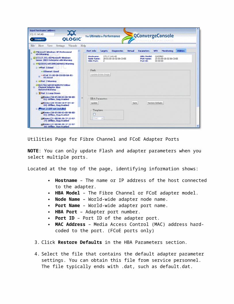
Saving the MPI Config Table
You can save and update the MPI configuration table for QLx81xx Converged Network Adapters using the adapter Utilities page. The Save operation reads the contents of the MPI configuration table in the adapter flash and exports the data to a specified DAT file.
To save the current MPI Config table:
1. In the system tree, select the adapter node for any Converged Network Adapter.2. Select the Advanced Utilities tab. The Advanced Utilities page appears in the content
pane. The following example illustrates the MPI Config Table section that shows the current table version stored in the selected adapter's flash.
MPI Config Table Section
3. Click the Save button. A browser pop-up window opens, displaying the information stored in the MPI configuration table.
4. Right-click anywhere on the browser window and select Save As from the pop-up menu. A Save As dialog box opens.
5. Navigate to a location where you want to save the MPI configuration table and enter a file name, as shown in the following illustration.
Save MPI Configuration Table as File Dialog Box
6. Click Save. A file Save Successful dialog box opens.

7. Click OK to close the dialog box.8. Click the close box [x] to close the browser's pop-up window when you're finished
reviewing the data file.
See Also
Viewing the Advanced Utilties Saving the Firmware Preload Table Updating the Firmware Preload Table Saving the Firmware Serdes Table Updating the Firmware Serdes Table Updating the MPI Config Table
Home > Managing Fibre Channel and FCoE Adapters and Ports > Using the Adapter's Advanced Utilities > Updating the MPI Config Table
Updating the MPI Config Table
You can save and update the MPI configuration table for QLx81xx Converged Network Adapters using the adapter Utilities page. The Update operation accepts a DAT file and writes its data to the flash on the adapter.
To update the MPI configuration table with a more current version:
1. In the system tree, select the adapter node for any QLx81xx Converged Network Adapter.2. Select the Advanced Utilities tab. The Advanced Utilities page appears in the content
pane. The following example illustrates the MPI Config Table section that shows the current table version stored in the selected adapter's flash.
MPI Config Table Section
3. Click the Update button. A file selection pop-up window opens, as shown in the following example.
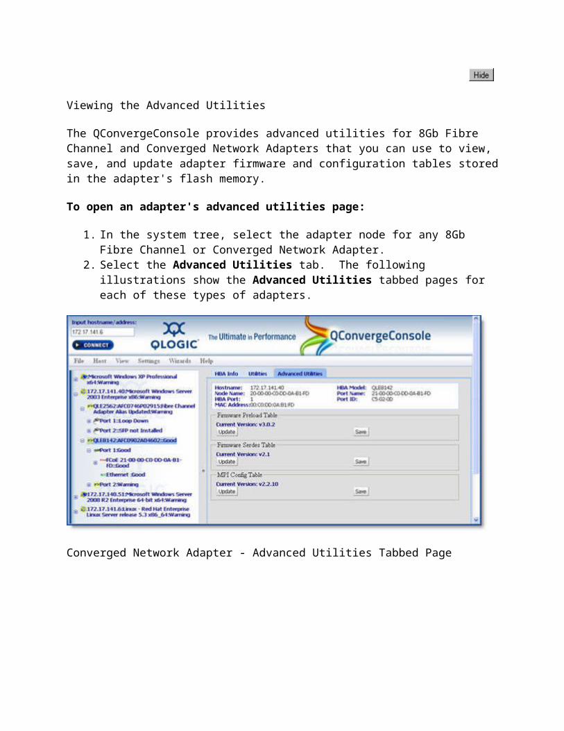
Choose File Dialog Box
4. Click Choose File and navigate to the location where you saved the .dat file you want to load, as shown in the following example.
Selecting DAT File in Open File Dialog Box
5. Select the file and click Open. The file selection pop-up window reappears, showing the selected file name, as shown in the following example.
Choose File Dialog Box with File Selection
6. Click Send to write the new MPI configuration table to the adapter's flash. The system checks to validate the version and displays a message box showing the version update, as shown in the following example.
Updating MPI Config Table Message
7. Click OK to accept the version change. The Security Check dialog box appears.8. In the Enter Password box, type the password, and then click OK. See Security Check.

If you failed to enter the correct password, a message box informs you that the update failed.
If you entered the correct password, a message box informs you that the update was successful.
9. Click OK to close the message box.
See Also
Viewing the Advanced Utilities Saving the Firmware Preload Table Updating the Firmware Preload Table Saving the Firmware Serdes Table Updating the Firmware Serdes Table Saving the MPI Config Table
Using Virtualization (NPIV)
Virtualization or NPIV (N_Port ID Virtualization) allows you to make the most of your server and Fibre Channel fabric. For instance, you can partition your server to support multiple operating systems at the same time, maximizing server utilization. By creating virtual ports from a single physical adapter port, you allow multiple initiators. QConvergeConsole facilitates creating multiple virtual ports from a single physical adapter port.
NOTE: NPIV is available for Windows operating systems and 4Gb and greater adapters only.
When using a virtual port, you cannot change the adapter parameters or update the drivers or flash memory on the physical adapter. Consequently, there is no Parameters tabbed page or Utilities page available when you click a virtual port. As a result, the following features are not available if you are using a Windows operating systems or VMWare drivers on Linux operating systems:
Adapter parameter settings Adapter parameter restore default Flash update from file Adapter parameter update from file Adapter parameter save to file Adapter parameter update from templates Target link speed (Intelligent Interleaf Factor) Boot device settings Driver settings Target list (unavailable in Windows only) LUN list (unavailable in Windows only)

However, the following pages are available and reflect the data from the physical adapter:
Port Info Targets Diagnostics VPD Monitoring (which shows real-time statistics) FCoE
NOTE: The Virtual page is not available for virtual ports.
Once you create a virtual port, you can view the same parameters available on the physical port from which you created the virtual port. The only differences between the virtual port and its physical parent is the www number and the port number. The only way to modify the parameters on a virtual port is to delete it, then create another one.
See Also
Creating Virtual Ports Deleting Virtual Ports
Creating Virtual Ports
Each physical port can support up to 64 virtual ports. QConvergeConsole lets you create one or more virtual ports at the same time.
NOTE: When mixing Fibre Channel and Converged Network Adapters on same host, you must use the same family of drivers to create the virtual port properly.
To create a virtual port in QConvergeConsole:
1. In the system tree, expand a 4Gb or better adapter node.2. Select the port in the system tree, as shown in the following example:

Select Port to Create a Virtual Port
3. Select the Virtual tab.
NOTE: Create vPort and Delete vPort are available only in Windows operating systems.
4. Click the Create vPort button, located at the bottom of the adapter image screen, as shown in the following example:

Click the Create vPort Button
The vPort WWN Generation dialog box appears, as shown in the following illustration:
vPort WWN Generation Dialog Box
In the Current WWN Generation section, the Generated WWN for the first virtual port appears. This is the WWN that is assigned to the vPort that you just created.
5. Use the Number of vPort(s) to Generate spinner to select the number of virtual ports to generate, then click Update. The vPort WWW Generation dialog box displays unique WWNs for the selected number of vPorts, as shown in the following example.
Multiple vPort WWN Generation Dialog Box
The generated WWN for multiple virtual ports supports the following:
The driver determines the number of vPorts allowed. For example, a Windows
driver that supports 16 ports can allow up to 15 virtual ports.
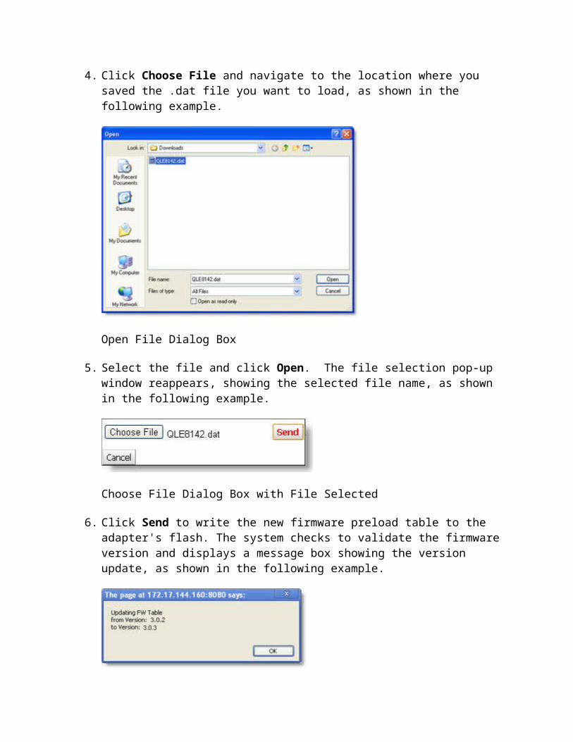
To generate a different set of randomly selected WWNs, click Generate to create a different one.
To change a particular WWN, type a different hex number (greater than 0x4) in the second field.
NOTE: The only number that changes is the second hex digit.
6. Click OK to accept the numbers in the Generated WWN fields. The Security Check dialog box opens, as shown in the following example.
Security Check Dialog Box
7. If you are creating more than one virtual port, select the save password for the current session option.
NOTE: If you do not select the save password for the current session option, QConvergeConsole creates only one virtual port at a time.
8. In the Enter Password field, type the password, then click OK. The newly created virtual ports, they appear in the left-hand frame of the page.
9. Click the browser Refresh button to refresh the screen, then reconnect to the hosts to view the updated system tree. The newly added virtual ports appear under the adapter physical port with the notation "Virtual Port n".
NOTE: When QLogic does not manage the name space under VMware, the port ID check does not work properly on QLE81xx adapter ports. Under these circumstances, the system tree displays all virtual ports as Virtual Port 1, regardless of the number of virtual ports assigned to each physical port on any QLE81xx adapter.
See Also
Deleting Virtual Ports Using Virtualization (NPIV)

Deleting Virtual Ports
To delete one or more virtual ports:
1. In the system tree, expand a 4Gb or better adapter node.2. Select the physical port that contains the virtual ports you want to delete, as shown in the
following example:
Selecting Port in Tree View
3. Select the Virtual tab. The Virtual tab appears in the content pane, as shown in the following example.
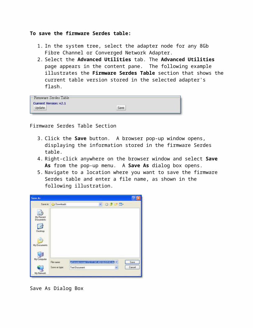
Adapter Port Virtual Page - With Configured Virtual Ports
NOTE: Create vPort and Delete vPort are available only in Windows operating systems.
4. Click the Delete vPort button, located at the bottom of the Adapter Port Virtual Page. A host dialog box opens, displaying a list of all vPorts.

Selecting Multiple Virtual Ports to Delete
5. Press the CTRL or Shift Key while multi-selecting virtual ports, then click Delete. The Security Check dialog box opens.
Security Check Dialog Box
6. Enter the administrative password, then click OK. The selected virtual ports clear from the screen. If successful, an Alert box opens, letting you know the deletion succeeded, as shown in the following example.

Successful vPort Deletion Alert Box
7. Click the browser Refresh icon, then reconnect to the Host to refresh the system tree.
See Also
Creating Virtual Ports Using Virtualization (NPIV)
Performing Diagnostics
The QConvergeConsole supports two diagnostic tests for Fibre Channel and FCoE ports: Loopback and Read/Write.
NOTE: You must use a loopback connector when running the loopback test, unless the operating system uses one of the driver versions listed in the Driver Versions That Do Not Require a Loopback Connector table. The read/write buffer test must be run without the loopback connector on a device (disk or tape) that supports the SCSI Read Buffer and SCSI Write Buffer commands.
When considering diagnostics, understand that:
Because diagnostic testing interrupts normal adapter operations,you should run these tests when no other activities are required of the adapter.
The adapter state reverts to pre-test conditions at the end of the testing process. Diagnostic tests read and write to sensitive areas on the adapter. Disruption of some diagnostic tests may require a complete update of the adapter's
critical memory areas.
NOTE: Although QConvergeConsole protects against normal operation interruption and testing disruption, it is your responsibility to ensure that the diagnostics are run without causing interruptions to other processes and disruptions to the actual testing process.
Loopback Test
The loopback test is external to the adapter. If the adapter port is in loop mode, you can run the loopback test with a loopback connector. If the adapter port is in point-to-point mode and attached to a switch, an echo test is run instead (no loopback connector is used). In addition, some driver versions do not require a loopback connector. See Preparing for the Loopback Test for information.
The test evaluates the ports (transmit and receive transceivers) on the adapter. More specifically, the loopback test transmits and receives (loopback) the specified data and checks for the frame CRC, disparity, and length errors.

To run a loopback test:
1. Prepare for the test (see Preparing for Diagnostic Testing).2. Set the diagnostic test parameters (see Setting the Diagnostic Test Parameters).3. Run the diagnostic test (see Running Diagnostic Tests).4. View the diagnostic test results (see Viewing the Diagnostic Test Results).5. Prepare for normal adapter operations (see Preparing for Normal Adapter Operations).
NOTE: The Loopback test is disabled if you are using inbox drivers with Red Hat 5.0 or SLES 10.0.
Read/Write Buffer Test
The read/write buffer test sends specified data through the SCSI Write Buffer command to a target device (disk or tape). It then reads the data back through the SCSI Read Buffer command and compares the data for errors. The test also compares the link status of the device before and after the read/write buffer test. If errors occur, the test indicates a broken or unreliable link between the adapter port and the device.
NOTE: Link Status is disabled if you are using inbox drivers with Red Hat 5.0 or SLES 10.0.
To run a read/write buffer test:
1. Prepare for the test (see Preparing for Diagnostic Testing).2. Set the diagnostic test parameters (see Setting the Diagnostic Test Parameters).3. Run the diagnostic test (see Running Diagnostic Tests).4. View the diagnostic test results (see Viewing the Diagnostic Test Results).
See Also
Installing a Loopback Connector
Preparing for the Loopback Test
NOTE: The Loopback test is disabled if you are using inbox drivers with Red Hat 5.0 or SLES 10.0.
Before running the loopback test:
1. Modify the Connection Options setting (see Modifying the Adapter Settings Connection Options Setting).
2. Attach a loopback connector to the Fibre Channel connector on the adapter port (see Installing a Loopback Connector).

NOTE: Skip this step under the following conditions (an echo test is run instead): • You have a 2xxx adapter that is connected to the fabric through a point-to-point connection (F-port). • The adapter is connected to a switch. • Your operating system has one of the driver versions listed in the table below.
1.
Driver Versions that Do Not Require a Loopback Connector
Operating System Driver Version
Windows 2000/Windows Server 2003 with SCSI miniport driver 8.2.3.11 and above
Windows XP Professional/Windows Server 2003/Windows Vista/Windows 2008 with STORport miniport driver
8.2.3.16 and above
Red Hat/SuSE Linux 6.06.00 and above
Solaris SPARC 4.12 and above
Solaris x86 4.15 and above
Novell NetWare 6.80 and above
3. If the adapter port is connected to the fabric through a point-to-point connection (F-port) and is connected to a switch, make sure the Connection Options setting is 1 - Point-to-Point Only. See Adapter Parameters for information about viewing and modifying the setting.
Home > Managing Fibre Channel and FCoE Adapters and Ports > Performing Diagnostics > Preparing for the Loopback Test > Installing a Loopback Connector
Installing a Loopback Connector
Before running the loopback test, you must install a loopback connector on the adapter port. Note the following about the loopback connector:

The loopback connector must be appropriate for the type of Fibre Channel adapter connector.
Be sure to select the appropriate adapter connector for testing. Each adapter connector displays in the QConvergeConsole system tree as an adapter port.
NOTE: Installing the connector stops normal adapter operations.
To install a loopback connector:
1. Disconnect the cable from the appropriate adapter connector.2. Install the loopback connector on the adapter connector.
Home > Managing Fibre Channel and FCoE Adapters and Ports > Performing Diagnostics > Preparing for the Loopback Test > Modifying the HBA Settings Connection Options Setting
Modifying the Adapter Settings Connection Options Setting
Before running the loopback test, the Connection Options setting must be set appropriately. See Adapter Parameters for information about viewing and modifying the setting.
NOTE: This procedure does not apply to QLE81xx and QMI81xx adapters since their Connection Options are not editable.
To modify the Connection Options setting:
1. Write down the current setting.2. Do one of the following:
o If the adapter port is not connected to the fabric through a point-to-point connection (F-port) and is not connected to a switch, change the setting to 0 - Loop Only, if not currently set to this option.
o If the adapter port is connected to the fabric through a point-to-point connection (F-port) and is connected to a switch, make sure the setting is 1 - Point-to-Point Only.
3. After completing the loopback test, change the Connection Options setting back to its original value.
Setting the Diagnostic Test Parameters
NOTE: This topic applies only to Fibre Channel and FCoE ports.
To set the loopback or read/write buffer test parameters:

1. Click the adapter port from the QConvergeConsole system tree.2. Click the Diagnostics tab, then click the General Diagnostics subtab (see the illustration
below).
Fibre Channel Adapter Port - General Diagnostics Page
The identifying information displays:
Hostname – The name or IP address of the host connected to the adapter. HBA Model – Adapter model number. HBA Port – The adapter port number. Node Name – The World-wide adapter node name. Port Name – The World-wide adapter port name. Port ID – The Port ID of the adapter port.
Test Configuration
The diagnostic test parameters are in the Test Configuration section. The parameters consist of the Data Pattern (jitter patterns) and Data Size in bytes.
Data Pattern sequences are the bit sequences that are transmitted by a serializer onto a link or bit sequences received by a deserializer from a link. The Data Pattern sets the test pattern for evaluating the jitter compliance of a fibre channel link. Test bit sequences have a significant impact on stressing the link's jitter characteristics.

For more information see American National Standards Institute (ANSI). Methodologies for Jitter and Signal Quality Specification - MJSQ Annex A - Test bit sequences.
In addition to selecting a Data Pattern, you must also select a Data Size in bytes. The maximum data size available is dependent on the frame size of the device you are testing and the kind of test you are conducting. See Adapter Parameters for more information about Frame Size.
Loopback/Echo tests support data sizes from 8 bytes to 2048 (2K) bytes.
NOTE: The following Data Size values apply to Linux operating systems only--2048, 4096, 8192 up to 65535 (2K bytes to 64K bytes).
Read/Write Buffer tests support data sizes from 8 bytes to 128 bytes.
NOTE: Echo tests are available when the HBA Port Connection Option is set to Point to Point Only. If Connection Option is set to Loop Only, the Loopback test is available.
The following Data Patterns are available for use with the:
Data Pattern Bit Sequence Notes
CRPATCompliant random data pattern in a valid fibre channel frame - sub clause A.2.2.4
The fibre channel frame sent during the Loopback diagnostic test does not match the MJSQ specification exactly (see reference below). To send this diagnostic frame, we use a SCSI FCP frame with a valid header. The modified SCSI FCP frame results in a CRC that does not match the MJSQ specification.
The cannot control the number of IDLES prior to sending the pattern frame.
For more information see American National Standards Institute (ANSI). Methodologies for Jitter and Signal Quality Specification - MJSQ Annex A - Test bit sequences.
CJTPAT Compliant jitter tolerance pattern in a valid fibre channel frame - sub clause A.2.3.3
The fibre channel frame sent during the Loopback diagnostic test does not match the MJSQ specification exactly (see reference below). To send this diagnostic frame, we use a SCSI FCP frame with a valid header. The modified SCSI FCP frame results in a CRC that does not match the MJSQ specification.
The cannot control the number of IDLES prior to sending the pattern frame.

For more information see American National Standards Institute (ANSI). Methodologies for Jitter and Signal Quality Specification - MJSQ Annex A - Test bit sequences.
CSPATSupply noise test sequence in a valid fibre channel frame - sub clause A.2.4.3
The fibre channel frame sent during the Loopback diagnostic test does not match the MJSQ specification exactly (see reference below). To send this diagnostic frame, we use a SCSI FCP frame with a valid header. The modified SCSI FCP frame results in a CRC that does not match the MJSQ specification.
The cannot control the number of IDLES prior to sending the pattern frame.
For more information see American National Standards Institute (ANSI). Methodologies for Jitter and Signal Quality Specification - MJSQ Annex A - Test bit sequences.
00 00000000
55 01010101
5A 01011010
A5 10100101
AA 10101010
FF 11111111
To use the HBA Diagnostics page to set the test parameters:
1. From the Data Pattern list, do one of the following:o Select a data byte or compliant jitter pattern.o Click Customized to specify your own eight-byte pattern. Enter the data in
hexadecimal format (0-FF) into the eight Customized boxes.o Click Random to randomly generate an eight-byte data pattern.
The data size sets the number of bytes transferred per test per iteration when the test is run.
2. From the Data Size list, click the number of bytes to transfer. Valid values are 8, 16, 32, 64, 128, 256, 512, 1024 and 2048. For Linux operating systems only, you can select data size values from 2048, 4096, 8192 up to 65535 (2K bytes to 64K bytes).
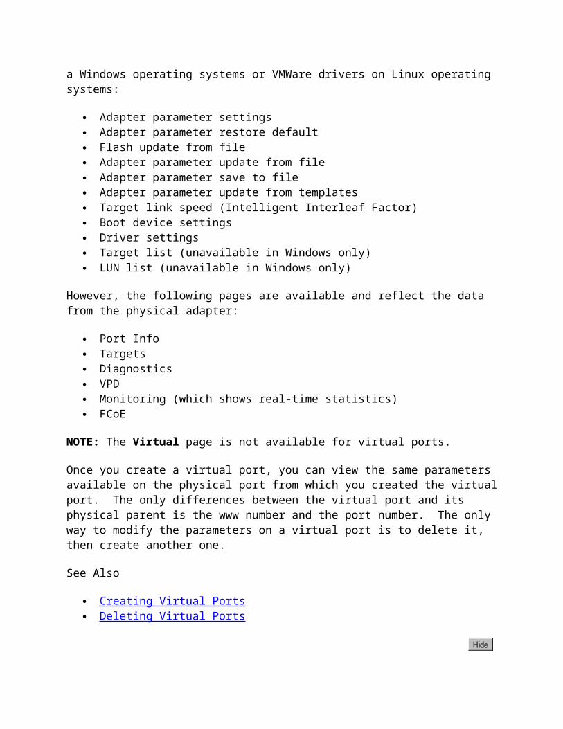
3. Do one of the following to set the test frequency:o In the Number of Tests field, type or select the number of tests you want to run.
Testing stops when the passes complete. The valid range is between 1 and 10,000.o Click the Test Continuously check box. You determine when testing stops.
4. From the On Error box, click one of the following to determine how errors are handled. This selection applies whether you entered the number of tests or selected test continuously.
o Ignore on Error – Ignores errors and continues the test sequence.o Stop on Error – Stops the test sequence once an error is encountered.o Loop on Error – Uses the same data pattern and test until the failure is cleared.
5. In the Test Increment field, type or select the number of passes you want to run before the test stops. The valid range is between 1 and 10,000, and must be less than or equal to the value in the Number of Tests box (see step 5). For example, if the Number of Tests box contains 100 and the Test Increment box contains 15, 100 tests are run in seven passes. The first six passes run 15 tests each; the seventh pass runs 10 tests (6 x 15 + 10 = 100).
6. When you finish setting the diagnostic test parameters, you are ready to start the diagnostic testing. See Running Diagnostic Tests.
NOTE: The test runs this number of passes before it stops on an error (if Stop on Error was selected in step 6) or stops when you select to stop testing (if Test Continuously was selected in step 5).
Running Diagnostic Tests
NOTE: The Loopback test is disabled if you are using inbox drivers with Red Hat 5.0 or SLES 10.0.
Once you have set the test parameters as described in Setting the Diagnostic Test Parameters, perform the following steps.
NOTE: The Loopback test is the only diagnostic test that supports QLx81xx and QMI81xx adapters, which require external loopback connectors.
To run the loopback or read/write buffer test:
1. Click the Loopback Test or Read/Write Buffer Test button.2. The diagnostic tests warning displays. Do one of the following:
o Click Yes if there are no I/ Os active and you want to proceed with the test.o Click No to cancel the diagnostic test.
3. If you selected Yes in step 2, a dialog box displays with the data pattern generated. Click Stop when you want to end the test.

NOTE: Run an echo test instead of a loopback test under the following conditions:
• You have a 2xxx adapter port that is connected to the fabric through a point-to-point connection (F-port).
• The adapter is connected to a switch. Your operating system has one of the driver versions listed in the Driver Versions That Do Not Require a Loopback Connector table.
Home > Managing Fibre Channel and FCoE Adapters and Ports > Performing Diagnostics > Viewing the Diagnostic Test Results
Viewing the Diagnostic Test Results
NOTE: The Loopback test is disabled if you are using inbox drivers with Red Hat 5.0 or SLES 10.0.
The Loopback Test Results section of the General Diagnostics page displays the results of a test run (see illustration below). The Test Status column indicates whether the test passed or failed. The remaining information pertains to error counters.

Diagnostic Test Results Section
NOTE: If you want to sort the existing entries in the table, click the column heading. A triangle displays in the heading, indicating an ascending sort (default). Click the triangle for a descending sort.
See Also
Loopback test results Read/write buffer test results
Home > Managing Fibre Channel and FCoE Adapters and Ports > Performing Diagnostics > Viewing the Diagnostic Test Results > Loopback Test Results
Loopback Test Results
NOTE: The Loopback test is disabled if you are using inbox drivers with Red Hat 5.0 or SLES 10.0.
The Loopback Test Results section provides the following information:
Tests Status – Whether the test passed or failed. The possible values:o Success – The test passed.o Error – CRC, disparity, or frame length errors occurred.o Failed – An error occurred when attempting to issue a command.o Loop down – The loop is down.
CRC Error – Number of CRC errors. Disparity Error – Number of disparity errors. Frame length error – Number of frame length errors.
The Loopback Test Results section shows a failed test. The Test Status column in the illustration below shows that the loopback test failed.

Diagnostic Test Results - Loopback Test Failed
See Also
Viewing the Diagnostic Test Results
Home > Managing Fibre Channel and FCoE Adapters and Ports > Performing Diagnostics > Viewing the Diagnostic Test Results > Read/Write Buffer Test Results
Read/Write Buffer Test Results
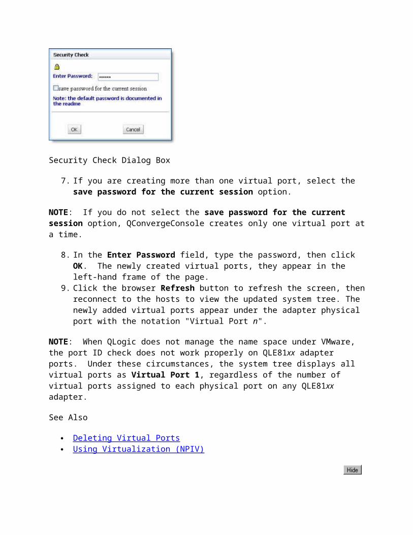
The Read/Write Buffer Test Results section provides the following information, as shown in the illustration below.
Diagnostic Test Results - Read/Write Buffer Test
Loop ID/Statuso The loop ID of the adapter when operating in loop mode.o The status of the test – whether the test passed or failed. The possible values:
o Success – The test passed. Error – A data miscompare or link status firmware error occurred. Failed – A link status error, SCSI write buffer error, or SCSI read buffer
error occurred. Unknown – The target was not present. Unsupported – The device does not support this test.
Data Miscompare – The possible values:o 0 (no data miscompares).o Device not present.o Get link status failed.o Read buffer failed.o R/W buffer not supported.

o Write buffer failed. Link Failure – Number of link failures. Sync Loss – Number of sync loss errors. Signal Loss – Number of signal loss errors. Invalid CRC – Number of invalid CRCs.
If the value in the Data Miscompare column is nonzero, you can view the miscompare information by double-clicking any column. The Diagnostic Details dialog box displays (see the illustration below).
Data Miscompare Results
When you finish viewing the miscompare information, click:
Next to view the details of the next miscompare. Previous to view the details of the previous miscompare. Close to return to the Diagnostics page.
Home > Managing Fibre Channel and FCoE Adapters and Ports > Performing Diagnostics > Viewing the Diagnostic Test Results > HBA Port Transceiver Details
Viewing Adapter Port Transceiver Details
The Tranceiver Details tabbed page, located in the Diagnostics page, displays the Digital Diagnostics Monitoring Interface for optical transceivers allowing access to device operating parameters. The Tranceiver Details page consists of two nested pages: General and Details.
NOTES:• The Tranceiver Details tabbed page is available only for 4Gb or greater Fibre Channel adapter devices.• The Tranceiver Details function is disabled if you are using inbox drivers with Red Hat 5.0 or SLES 10.0.
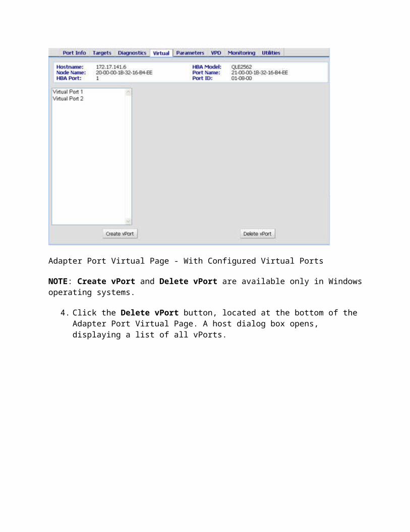
The General page shows an overview of the status data from the optical transceiver device. The Details page (see the illustration below) shows detailed digital diagnostic data from the optical transceiver device.
SFF-DMI Page - General Page
Identifying information displays above the nested pages:
Hostname – Name or IP address of the host connected to the adapter. HBA Model – Model number for the adapter (any ISP 2422/2432 based adapter). HBA Port – Adapter port number. Node Name – World wide adapter node name. Port Name – World wide adapter port name.

Port ID – Port ID of the adapter port.
General Page
The General page contains the Media Information section and the Diagnostic Data section.
Media Information
On the General tab, the following information displays in the Media Information section:
Vendor – Indicates the name, commonly accepted abbreviation, SCSI company code or the stock exchange code for the company that provides the transceiver device.
Part Number – Indicates the vendor part number or product name of the transceiver device. A value of zero indicates that the part number is unknown.
Revision – Indicates the vendor product revision number of the transceiver device. A value of zero indicates that the revision number is unspecified.
Serial Number – Indicates the vendor serial number for the transceiver device. Type – Describes the transceiver device based on information that the software reads from the
device.
For instance,the type 400-M6-SN-I describes a transceiver device that has a speed of 400 MBytes/sec (400), uses a multi-mode 62.5 m (M6) laser, which is a shortwave laser without OCF (SN) for an intermediate distance (I).
Speed – indicates the data transfer rate for the transceiver device in Mbytes/sec.
Diagnostic Data
Diagnostic data displays in the Diagnostic Data section showing the existing Value, Status, High Alarm value,High Warning value, Low Warning value, and Low Alarm value for the following data:
Temperature (C) – temperature of the transceiver device in degrees centigrade. Voltage (V) – voltage of the transceiver device power supply in volts. Tx Bias (mA) – transmitting laser bias current in mA. Tx Power (mW) – coupled transmitter output power of the laser in mW. Rx Power (mW) – received optical power in mW.
The Value shows the existing number value for the datum. The Status shows its rank as Normal, Warning or Fault. Normal status displays a green cell in the Diagnostic Data section. Fault status displays as a red cell and warning status displays as a yellow cell. A fault status requires immediate action.
Each datum has a High Alarm and a Low Alarm value. If a datum exceeds the High Alarm value or falls below the Low Alarm value, the conditions are likely to cause an inoperable link and require immediate action.

Additionally, each datum has a High Warning value and Low Warning value. Warnings indicate conditions outside the normally guaranteed bounds, but are not necessarily causes for immediate link failures.
NOTE: Certain warning flags may represent the manufacture's end of life indicators.
Details Page
The Details page (see the illustration below) shows detailed digital diagnostic data from the optical transceiver device. Please refer to SFF-8472 Specification for Diagnostic Monitoring Interface for Optical Xcvrs, Revision 9.3 August 1, 2002 for a detailed explanation of the diagnostic data displayed on the Details page.
Transceiver Details Page

Preparing for Normal Adapter Operations
To resume normal adapter operations when loopback testing is complete:
1. Remove the loopback connector from the adapter connector.2. Reconnect the cable that you disconnected.3. Modify the adapter settings Connection Options back to its previous setting (see
Modifying the Adapter Settings Connection Options Setting).
Managing the QLE8xxx FCoE Port
Selecting an FCoE port on a QLE81xx or QLE82xx adapter node in the system tree displays the same pages available for other adapter ports. It also displays an FCoE tab which provides four sub-pages for General Information, Data Center Bridging, DCE Statistics, and DCBX TLV details.
NOTE: QConvergeConsole supports this feature on Linux, Solaris, and Windows platforms.
For details, see the following topics:
Viewing FCoE Information Viewing Data Center Bridging Viewing DCE Statistics Viewing TLV Details
Managing iSCSI Ports
Selecting an iSCSI port in the QConvergeConsole's system tree displays a set of information and configuration pages in the content pane. While some of these pages display information regarding the selected port, others let you modify port and adapter configuration settings.
Except where indicated, parameters described in the topic examples exist on all iSCSI ports, which reside on a Converged Network Adapter (QLE82xx).
The following topics describe how to use the adapter port information and configuration pages:
Viewing iSCSI Port Information Viewing and Updating iSCSI Port Parameters Configuring iSCSI Port Targets

Viewing and Updating iSCSI Port Statistics Pinging an iSCSI Port Target
Viewing iSCSI Port Information
To view iSCSI port information:
1. In the QConvergeConsole system tree, expand a QLE82xx adapter node to display its ports.
2. Expand the Port, and then select the iSCSI port beneath it, as shown in the following example.
Selecting the iSCSI Port - QLE82xx Converged Network Adapter
3. Select any of the tabs in the content pane to display configuration details related to the selected iSCSI port. The top portion of each of these pages provides general information that identifies the selected adapter and iSCSI port as described in the following paragraphs:
Hostname – IP address or name of the host in which the adapter resides. HBA Model – Adapter model, such as QLE8242. Port State – Adapter port state. Possible states may include:
Ready Link Up Link Down Refreshing

Busy Commit Needed HBA Diag Mode Not Initialized Reboot Needed Unknown Link Down
IPv4 Address – IP address of the iSCSI adapter port. MAC Address – MAC address of the iSCSI adapter port. Port Alias – iSCSI adapter port alias name. This is the symbolic name you assign
to the iSCSI adapter port for identification purposes. iSCSI Name – By default, this is the QLogic manufacturing name of the iSCSI
port. This name concatenates adapter port details that uniquely identifies the selected iSCSI port. For example, the name shows the adapter port type, manufacturer, ASIC, and serial number.
4. Select the Port Info tab to display general information about the selected port. The bottom section of the Port Info page identifies the following port attributes:
Serial Number – Serial number assigned at the factory to uniquely identify the adapter.
Driver Version – Type and version of driver. The driver depends on the operating system installed on the host server.
Firmware Version – iSCSI firmware version. BIOS Version – BIOS version. Connection Type – Type of adapter port connector, such as Copper or Fiber. Duplex Setting – Port duplex setting (Half/Full/Auto Duplex) Flow Control – Port flow control (Enabled/Disabled). Link Speed – Speed of port connection(100/1000 Mbs). HBA Instance – Adapter instance number.
NOTEs:- For fiber connections and daughter cards, only 1Gbs link speed is supported.- For copper connections in manual mode, only 100Mbs link speed is supported.
See Also
Managing iSCSI Ports Viewing and Updating iSCSI Port Parameters Configuring iSCSI Port Targets Viewing and Updating iSCSI Port Statistics Pinging an iSCSI Port Target
Viewing and Updating iSCSI Port Parameters

All QLE82xx iSCSI ports have similar fields and options that you can view and edit through the iSCSI port's Parameters page.
To view or modify the adapter parameters from the Parameters page:
1. In the QConvergeConsole system tree, expand a QLE82xx adapter node to display its ports.
2. Expand the Port, and then select the iSCSI port beneath it,3. Select the Parameters tab. The Parameters page appears, as shown in the following
example.
Parameters Page - iSCSI Port
Located at the top of the page, identifying information shows:
Hostname – IP address or name of the host in which the adapter resides. HBA Model – Adapter model, such as QLE8242. Port State – Adapter port state. IPv4 Address – IP address of the iSCSI adapter port. MAC Address – MAC address of the iSCSI adapter port.

Port Alias – iSCSI adapter port alias name. This is the symbolic name you assign to the iSCSI adapter port for identification purposes.
iSCSI Name – By default, this is the QLogic manufacturing name of the iSCSI port. This name concatenates adapter port details that uniquely identifies the selected iSCSI port. For example, the name shows the adapter port type, manufacturer, ASIC, and serial number.
4. Select the desired adapter parameters using the sub-tabs described in the following topics: General Settings (see Configuring iSCSI Port Names and Restoring iSCSI Port
Parameters to the Factory Defaults Network Settings (see Setting the IP Address and Router Address) Boot Settings (see Configuring Boot Settings)
See Also
Managing iSCSI Ports Viewing iSCSI Port Information Configuring iSCSI Port Targets Viewing and Updating iSCSI Port Statistics Pinging an iSCSI Port Target
Home > Managing iSCSI Ports > Viewing and Updating iSCSI Port Parameters > Restoring Parameters to the Factory Defaults
Restoring iSCSI Port Parameters to the Factory Defaults
To reset the parameters to the factory defaults:
1. In the QConvergeConsole system tree, expand a QLE82xx adapter node to display its ports.
2. Expand the Port, and then select the iSCSI port beneath it.3. Select the Parameters tab. The Parameters page appears, as shown in the following
example.

Parameters Page - iSCSI Port with Modified Parameters
4. On the General Settings page, click Restore Port Defaults. The Restore Factory Defaults dialog box opens, as shown in the following example.

Restore Factory Defaults Dialog Box
5. Select which default settings you want to restore: If you want to restore all default iSCSI port settings, click Restore All Defaults. If you want to retain specific modified settings, click Restore Selective Defaults,
then select the check box for each individual item to restore.
6. Click Restore Defaults. The Security Check dialog box appears.7. In the Enter Password box, type the password, and then click OK. See Security Check.
The buttons on the General Settings page appear dimmed during the update.
See Also
Viewing and Updating iSCSI Port Parameters Configuring iSCSI Port Names Setting the IP Address and Router Address Configuring Boot Settings
Home > Managing iSCSI Ports > Viewing and Updating iSCSI Port Parameters > Configuring iSCSI Port Names
Configuring the iSCSI Port Names
You can modify the existing iSCSI port iSCSI name. You can also assign an iSCSI port iSCSI alias name.
Modifying the Port iSCSI Name
Unless your system requires that you change the name, we recommend that you use the default iSCSI port name as defined by QLogic manufacturing.
NOTE: If you modify the default iSCSI port name, you cannot reset the name to the original default value. Therefore, write down the default iSCSI port name before changing it.
To modify the iSCSI port name:
1. In the QConvergeConsole system tree, select the iSCSI port. 2. Click the Parameters tab to view the General Settings page.3. In the Port iSCSI Name box, type the desired iSCSI name. 4. Click Save Port Settings. The Security Check dialog box appears.5. In the Enter Password box, type the password, and then click OK. See Security Check.

Assigning the Port iSCSI Alias
The iSCSI port alias name is a symbolic name that you can assign to the iSCSI port for identification purposes.
To assign or modify the iSCSI port alias:
1. In the QConvergeConsole system tree, select the iSCSI port. 2. Click the Parameters tab to view the General Settings page.3. Type the alias iSCSI name in the Port iSCSI Alias box. 4. Click Save Port Settings. The Security Check dialog box appears.5. In the Enter Password box, type the password, and then click OK. See Security Check.
See Also
Viewing and Updating iSCSI Port Parameters Restoring iSCSI Port Parameters to the Factory Defaults Setting the IP Address and Router Address Configuring Boot Settings
Home > Managing iSCSI Ports > Viewing and Updating iSCSI Port Parameters > Setting the IP Address and Router Address
Setting the IP Address and Router Address
NOTE: Save Network Only and IPv6 features are not available and appear dimmed if you are:
Using inbox/ioctl module drivers with Red Hat 4 and 5 and SLES 10, – Or – Do not have ACB (Alternate Control Block) support with the proper hardware configuration, drivers and firmware.
If you download the standard drivers and latest firmware from the QLogic Web site, you can access the Save Network Only function and IPv6 features.
You can set IP addresses for adapters that support IPv4 protocols and link local and routable addresses for adapters that support the IPv6 protocol. You can set these addresses to use a dynamically assigned IP address or specify a fixed IP address.
If you are using adapters that support IPv6, link local addresses are within the same subnet. When you require addresses outside the subnet, use routable addresses. You can set the routable address automatically or manually. You can also set the default router automatically or manually.

Setting the IP addresses, link local addresses, and router addresses require you to navigate to the Parameters page.
To set IP addresses:
1. In the QConvergeConsole system tree, expand a QLE82xx adapter node to display its ports.
2. Expand the Port, and then select the iSCSI port beneath it.3. Select the Parameters tab and click the Network Settings tab. The Network Settings
page opens, as shown in the following example.
iSCSI Port Parameters - Network Settings Page
Setting the IP Address or Local Link Address Automatically
On the Parameters - Network Settings page:
IPv4-IP Address
1. In the IPv4 area, select the Enable IPv4 Address check box. The IPv4 area is enabled.2. Click Obtain IP address automatically (DHCP), and then click one of the following:
1. Refresh to renew the user interface with previously saved adapter configuration settings. If you click Refresh before saving the adapter configuration settings, the settings changes present in the user interface are lost and not saved to the card.
2. Save Port Settings to save all adapter configuration settings to the adapter. This command initiates an adapter reset.
3. Save Network Only to save only the network settings for the adapter configuration. The Save Network Only command does not initiate an adapter reset.
IPv6-Link Local Address
1. In the IPv6 area, select the Enable IPv6 Addresses check box. The IPv6 area is enabled.2. Click Obtain IPv6 link local address automatically, and then click one of the following
buttons:o Refresh to renew the user interface with previously saved adapter configuration
settings. If you click Refresh before saving the adapter configuration settings, the settings changes present in the user interface are lost and not saved to the card.
o Save Port Settings to save all adapter configuration settings to the adapter. This command initiates an adapter reset.
o Save Network Only to save only the network settings for the adapter configuration. The Save Network Only command does not initiate an adapter reset.
Setting the IP Address or Link Local Address Manually
On the Parameters - Network Settings page:
IPv4-IP Address
1. In the IPv4 area, select the Enable IPv4 Address check box. The IPv4 area is enabled.2. In the IPv4 area, click Use the following IP address.3. In the boxes, type the IP Address, Subnet Mask, and Gateway.4. When you finish entering the settings for the IP address, click one of the following
buttons:1. Refresh to renew the user interface with previously saved adapter configuration
settings. If you click Refresh before saving the adapter configuration settings, the settings changes present in the user interface are lost and not saved to the card.
2. Save Port Settings to save all adapter configuration settings to the adapter. This command initiates an adapter reset.

3. Save Network Only to save only the network settings for the adapter configuration. The Save Network Only command does not initiate an adapter reset.
IPv6-Link Local Address
1. In the IPv6 area, select the Enable IPv6 Addresses check box. The IPv6 area is enabled.2. In the IPv6 area:
a. Select Use the following link local address. The address state appears.b. Type the link local ID in the Link Local ID (8 bytes) box.
NOTE: The "fe80" prefix does not appear in the Local Link ID box. When configuring a link local address manually, you may enter “fe80” as part of the address, but it does not show after the save is complete.
3. When you finish entering the settings for the link local address, click one of the following buttons:
a. Refresh to renew the user interface with previously saved adapter configuration settings. If you click Refresh before saving the adapter configuration settings, the settings changes present in the user interface are lost and not saved to the card.
b. Save Port Settings to save all adapter configuration settings to the adapter. This command initiates an adapter reset.
c. Save Network Only to save only the network settings for the adapter configuration. The Save Network Only command does not initiate an adapter reset.
Setting Routable Addresses (IPv6) Automatically
On the Parameters - Network Settings page:
1. In the IPv6 area, select the Enable IPv6 Addresses check box. The IPv6 area is enabled.2. Select Obtain routable addresses automatically (R).3. Set the default router automatically or manually.4. When you finish entering the settings for the default router addresses, click one of the
following buttons:o Refresh to renew the user interface with previously saved adapter configuration
settings. If you click Refresh before saving the adapter configuration settings, the settings changes present in the user interface are lost and not saved to the card.
o Save Port Settings to save all adapter configuration settings to the adapter. This command initiates an adapter reset.
o Save Network Only to save only the network settings for the adapter configuration. The Save Network Only command does not initiate an adapter reset.
Setting Routable Addresses (IPv6) Manually

On the Parameters - Network Settings page:
1. In the IPv6 area, select the Enable IPv6 Addresses check box. The IPv6 area is enabled.2. Click Use the following routable addresses.3. Type each of two routable addresses in the Routable Address 1 and Routable Address
2 boxes. The address states appear.4. Set the default router automatically or manually. 5. When you finish entering the settings for the default router addresses, click one of the
following buttons:o Refresh to renew the user interface with previously saved adapter configuration
settings. If you click Refresh before saving the adapter configuration settings, the settings changes present in the user interface are lost and not saved to the card.
o Save Port Settings to save all adapter configuration settings to the adapter. This command initiates an adapter reset.
o Save Network Only to save only the network settings for the adapter configuration. The Save Network Only command does not initiate an adapter reset.
Setting the Default Router (IPv6) Automatically
On the Parameters - Network Settings page:
1. In the IPv6 area, click the Enable IPv6 Addresses check box in the IPv6 area. The IPv6 area is enabled.
2. Click Use the following routable addresses.3. In the Default router address box, type this symbol ::, which is equivalent to setting the
IP address to zeros. The default router is automatically discovered if one is available. The Default Router State appears, as well as the Router Adv. Link MTU.
4. When you finish setting the default router address automatically, click one of the following buttons:
o Refresh to renew the user interface with previously saved adapter configuration settings. If you click Refresh before saving the adapter configuration settings, the settings changes present in the user interface are lost and not saved to the card.
o Save Port Settings to save all adapter configuration settings to the adapter. This command initiates an adapter reset.
o Save Network Only to save only the network settings for the adapter configuration. The Save Network Only command does not initiate an adapter reset.
Setting the Default Router (IPv6) Manually
On the Parameters - Network Settings page:
1. In the IPv6 area, click the Enable IPv6 Addresses check box. The IPv6 area is enabled.2. Click Use the following routable addresses.

3. In the Default router address box, type the default router address. The Default Router State appears, as well as the Router Adv. Link MTU.
4. When you finish entering the settings for the default router addresses, click one of the following buttons:
o Refresh to renew the user interface with previously saved adapter configuration settings. If you click Refresh before saving the adapter configuration settings, the settings changes present in the user interface are lost and not saved to the card.
o Save Port Settings to save all adapter configuration settings to the adapter. This command initiates an adapter reset.
o Save Network Only to save only the network settings for the adapter configuration. The Save Network Only command does not initiate an adapter reset.
See Also
Viewing and Updating iSCSI Port Parameters Restoring iSCSI Port Parameters to the Factory Defaults Configuring iSCSI Port Names Configuring Boot Settings
Configuring Boot Settings
To configure the BIOS boot settings:
1. In the QConvergeConsole system tree, expand a QLE82xx adapter node to display its ports.
2. Expand the Port, and then select the iSCSI port beneath it.3. Select the Parameters tab and click the Boot Settings tab. The Boot Settings page
opens, as shown in the following example.

iSCSI Parameters - Boot Settings Page
Located at the top of the page, identifying information shows:
Hostname – IP address or name of the host in which the adapter resides. HBA Model – Adapter model, such as QLE8242. Port State – Adapter port state. IPv4 Address – IP address of the iSCSI adapter port. MAC Address – MAC address of the iSCSI adapter port. Port Alias – iSCSI adapter port alias name. This is the symbolic name you assign
to the iSCSI adapter port for identification purposes. iSCSI Name – By default, this is the QLogic manufacturing name of the iSCSI
port. This name concatenates adapter port details that uniquely identifies the selected iSCSI port. For example, the name shows the adapter port type, manufacturer, ASIC, and serial number.
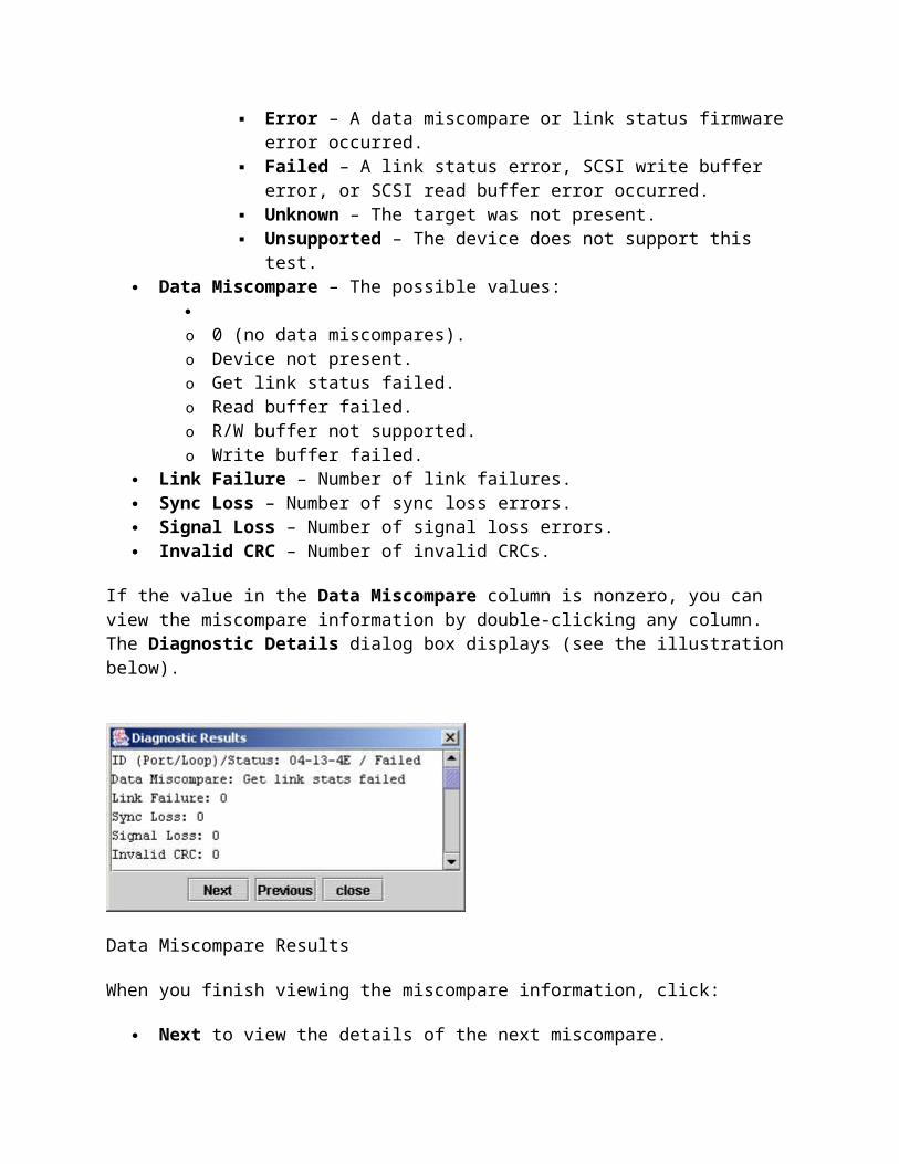
4. Select the BIOS Boot Mode Setting: (This feature is unavailable if the BIOS/UEFI Boot is Disabled message appears.)
3. Disabled – Disables booting from an iSCSI target with this iSCSI port.
o Manual – Enables booting from either the primary or secondary iSCSI boot targets configured for this port.
o DHCP – Enables automatic configuration of iSCSI boot targets using DHCP.
5. If the adapter has been configured with a DHCP Vendor ID (from QLogic OEMs), then the DHCP Boot Type can be configured as a Root Path, Vendor ID ,or Auto. The DHCP Vendor ID appears if you assigned it.
6. Select the Primary Boot Device ID. You can find the primary boot device ID on the Target Settings page by looking in the Target ID column under Target Configuration.
7. Select the Primary Boot LUN.8. Select the Secondary Boot Device ID. You can find the secondary boot device ID on
the Target Settings page by looking in the Target ID column under Target Configuration area.
9. Select the Secondary Boot LUN.10. Click Save BIOS/UEFI Only.11. When you finish entering the settings for boot, click one of the following:
o Refresh to renew the user interface with previously saved adapter firmware configuration settings. If you click Refresh before saving the configuration settings, the settings changes present in the user interface are lost and not saved to the card.
o Save Port Settings to save all firmware configuration settings to the adapter. This command initiates an adapter reset.
o Save Network Only to save only the network settings for the adapter firmware configuration. The Save Network Only command does not initiate an adapter reset.
NOTE: The Save Network Only function is not available if you are:
Using inbox/ioctl module drivers with Red Hat 4 and 5 and SLES 10, – Or – Do not have ACB (Alternate Control Block) support with the proper hardware configuration, drivers and firmware.
If you download the standard drivers and latest firmware from the QLogic Web site, you can access the Save Network Only function.
See Also
Viewing and Updating iSCSI Port Parameters Restoring iSCSI Port Parameters to the Factory Defaults

Configuring iSCSI Port Names Setting the IP Address and Router Address
Configuring iSCSI Port Targets
After configuring the iSCSI port, you can add and configure iSCSI targets. The following topics describe how to configure targets and assign CHAP names and secrets to targets:
Configuring iSNS to Automatically Discover Targets Configuring Specific Targets Authenticating Targets (CHAP)
See Also
Managing iSCSI Port s Viewing iSCSI Port Information Viewing and Updating iSCSI Port Parameters Configuring iSCSI Port Targets Viewing and Updating iSCSI Port Statistics Pinging an iSCSI Port Target
Configuring iSNS (iSCSI Name Service) to Automatically Discover Targets
The Configure iSNS to Automatically Discover Targets section of the Target iSNS Config page allows you to use an iSNS server to automatically discover targets. Target portals are not automatically logged in. Use this page to select which target portals to log in.
NOTE: iSCSI drivers distributed with RHEL 4.5, 4.6, 5.0, and 5.1 do not support iSNS target discovery.
To configure iSNS to automatically discover targets:
1. In the QConvergeConsole system tree, expand a QLE82xx adapter node to display its ports.
2. Expand the Port, and then select the iSCSI port beneath it.3. Click the Target Options tab, and then the Target iSNS Config tab, if not already
selected. The Target iSNS Config page opens within the Target Options page, as shown in the following example.

Target iSNS Conguration Page
4. Select the Enable iSNS check box.5. Depending on the type of IP address that the iSNS server uses, select either IPv4
Address or IPv6 Address.6. Enter either the IPv4 IP address or the IPv6 IP Address.7. If desired, set the iSNS TCP Port. The value entered must match the TCP port number of
the iSNS server to which you are trying to connect. Typically, it would be the default value of 3205.
8. When you finish entering the settings, click Save Port Settings to save all firmware configuration settings to the adapter. The Security Check dialog box appears.
9. In the Enter Password box, type the password, and then click OK. See Security Check.
See Also

Configuring iSNS to Automatically Discover Targets Configuring Specific Targets Authenticating Targets (CHAP)
Configuring Specific Targets
NOTES:• If you want to modify these parameters for an existing target, use the following procedures as appropriate (skipping steps 2 through 5).
• If you want to delete a target, select the target and click the red minus sign (-) on the right.
To configure a specific iSCSI target:
1. In the QConvergeConsole system tree, expand a QLE82xx adapter node to display its ports.
2. Expand the Port, and then select the iSCSI port beneath it.3. Click the Target Options tab, and then the Target Settings tab. The Target Settings
page opens within the Target Options page, as shown in the following example.

Target Settings Page
The target configuration section shows the current target configuration and enables you to configure these and additional targets on this adapter port.
4. Click the Add button. The IP Address dialog box opens. 5. Type the IP address of the target to which you want to connect, and then click OK.6. Double-click the iSCSI Name column. Type the iSCSI name of the target.7. If you want to enable the target, select the target's Enable check box. If this check box is
not selected, the target is visible, but not accessible, to the adapter.8. If you want to bind this target to the adapter (the Bind check box was not selected), select
the target's Bind check box.9. Add other targets as needed.10. If you want all of the targets to be restored when the adapter is reset, select the Dynamic
check box.

11. Click Save Target Settings and enter the administrative password when prompted to do so. The adapter:
Connects to the target. Makes these new targets available on the Target Settings page.
NOTE: QLogic recommends restarting the host PC for the operating system to recognize the new targets.
The adapter restarts and attempts to connect to the configured targets.
See Also
Configuring iSNS to Automatically Discover Targets Configuring Specific Targets Authenticating Targets (CHAP)
Authenticating Targets (CHAP)
The iSCSI firmware uses the Challenge Handshake Authentication Protocol (CHAP) as an authentication mechanism between iSCSI initiators (iSCSI ports) and attached devices (targets). You can enable or disable authentication for a specific target or for all targets attached to the iSCSI port.
NOTE: To use CHAP authentication, the targets attached to the adapter must support the CHAP protocol.
To set up CHAP for the iSCSI port and the attached devices:
1. In the QConvergeConsole system tree, expand a QLE82xx adapter node to display its ports.
2. Expand the Port, and then select the iSCSI port beneath it.3. Click the Target Options tab, and then click the Target Settings tab. The Target
Settings page opens within the Target Options page, as shown in the following example.

Target Settings Page (Target Options)
4. Click Config CHAP. The authentication configuration dialog box opens, as shown in the following example.

Authentication Configuration Dialog Box (CHAP Page)
The authentication configuration dialog box contains three tables:
Targets (assign CHAP Name/Secret to targets) CHAP Entries (CHAP entries available for assignment) Target Table (BIDI or Peer CHAP Entries)
5. To enable an initiator name and initiator secret:
a. Add a CHAP entry in the CHAP Entries table by clicking to the right of the CHAP Entries table. A new line appears in the CHAP Entries table.
b. Enter the Initiator Name and Initiator Secret directly into the CHAP Entries table.
c. In the Targets table, assign the Chap Name/Secret pair by typing the information directly into the Targets table.
d. After target data is saved, this CHAP entry assignment is active.e. To remove a CHAP entry from the CHAP Entries table, select the entry and
click to the right of the CHAP Entries table.6. If you want the adapter (initiator) to authenticate the target:
a. Add a Target Table CHAP entry by clicking to the right of the Target Table.b. Enter a Target Name and a Target Secret.c. In the Targets table select the Bidi check box of the target you want to
authenticate.d. After target data is saved, the CHAP entry assignment is active.

e. To remove a Target Table CHAP entry, select the entry and click to the right of the Target Table.
Entering Secrets
Most users enter secrets in the default ASCII mode. To enter a more complex secret, use hexadecimal mode. Hex mode allows values that do not have an equivalent standard character. In hexadecimal mode, the CHAP values range from 00 to FF, which is equivalent to standard base10 value range from 0 to 255.
To enter secrets:
1. Under Format of CHAP Secrets, click Hex (Two hex digits per CHAP secret octet) to create secrets in hex. If you want create secrets in ASCII, select ASCII.
NOTE: Toggling between Hex and ASCII automatically converts the hex representation to its ASCII equivalent, if one exists. CHAP secrets in ASCII are automatically converted to their hex equivalent.
2. In either the CHAP Entries table or Target Table, type the secrets.3. If you are using hexadecimal, type a two-digit hex character code for each hex digit that
is part of the secret.
4. To enable one default secret for bidirectional target authentication, select the Default Secret? check box corresponding to the appropriate Target Name/Target Secret pair in the Target Table.
See Also
Configuring iSNS to Automatically Discover Targets Configuring Specific Targets
Home > Managing iSCSI Ports > Viewing and Updating iSCSI Port Statistics
Viewing and Updating iSCSI Port Statistics
The iSCSI port's Monitoring page lets you view iSCSI port statistics, which provide information about an iSCSI port's iSCSI, TCP, IP, and MAC layers.
This topic provides steps for:
Viewing iSCSI port statistics

Resetting and refreshing iSCSI port statistics
Viewing iSCSI Port Statistics
To view statistical information about an iSCSI port:
1. In the QConvergeConsole system tree, expand a QLE82xx adapter node to display its ports.
2. Expand the Port, and then select the iSCSI port beneath it.3. Click the Monitoring tab to open the Monitoring - Statistics page (see the illustration
below).
Monitoring - Statistics Page
The iSCSI port identifying information includes:
Hostname – IP address or name of the host in which the adapter resides. HBA Model – HBA instance number and HBA model, such as QLE8242. Port State – Adapter port state. IPv4 Address – IP address of the iSCSI adapter port. MAC Address – The MAC address of the iSCSI adapter port.

iSCSI Name – By default, this is the QLogic manufacturing name of the iSCSI port. This name concatenates adapter port details that uniquely identifies the selected iSCSI port. For example, the name shows the adapter port type, manufacturer, ASIC, and serial number.
The Statistics sub-tab shows the parameters and their value based on the following type of card:
QLE82xx iSCSI Port Statistics
Resetting and Refreshing iSCSI Port Statistics
When an iSCSI adapter resets, the iSCSI port statistics counters reset to their initial values of zero. When an iSCSI adapter refreshes, the iSCSI port statistics counters update.
You can immediately reset or refresh the iSCSI port statistics counters as follows:
To set the baseline for statistics counters to the current counts, click Set Baseline. To reset the statistics counters to zero, click Clear Baseline. To immediately update the statistics counters, click Refresh Counters.
See Also
Managing the QLE82 xx iSCSI Port Viewing iSCSI Port Information Viewing and Updating iSCSI Port Parameters Configuring iSCSI Port Targets Viewing and Updating iSCSI Port Statistics Pinging an iSCSI Port Target
Home > Managing iSCSI Ports > Viewing and Updating iSCSI Port Statistics > QLE82xx iSCSI Port Statistics
QLE82xx iSCSI Port Statistics
The QLE82xx iSCSI port parameters that appear on the Monitoring - Statistics page are as follows:
MACTxFramesCount – MAC transmitted frame count MACTxBytesCount – MAC transmitted byte count MACTxMulticast – MAC transmitted multicast MACTxBroadcast – MAC transmitted broadcast MACTxPauseFrames – MAC transmitted pause frames

MACTxControlFrames – MAC transmitted control frames MACTxDeferrals – MAC transmitted deferrals MACTxExcessDeferrals – MAC transmitted excess deferrals MACTxLateCollisions – MAC transmitted late collisions MACTxAborts – MAC transmitted aborts MACTxSingleCollisions – MAC transmitted single collisions MACTxMultipleCollisions – MAC transmitted multiple collisions MACTxCollisions – MAC transmitted collisions MACTxFramesDropped – MAC transmitted frames dropped MACTxJumboFrames – MAC transmitted jumbo frames MACRxFramesCount – MAC received frame count MACRxBytesCount – MAC received byte count MACRxUnknownControlFrames – MAC received unknown control frames MACRxPauseFrames – MAC received pause frames MACRxControlFrames – MAC received control frames MACRxDribble – MAC received dribble MACRxFrameLengthError – MAC received frame length errors MACRxJabber – MAC received jabber MACRxCarrierSenseError – MAC received carrier sense errors MACRxFramesDiscarded – MAC received discarded frames MACRxFramesDropped – MAC received dropped frames MACCRCErrorCount – MAC CCR error count MACEncodingErrorCount – MAC encoding error count MACRxLengthErrorCountLarge – MAC received large length error count MACRxLengthErrorCountSmall – MAC received small length error count MACRxMulticast – MAC received multicast count MACRxBroadcast – MAC received broadcast count IPTxPacketsCount – IP transmitted packet count IPTxBytesCount – IP transmitted byte count IPTxFragmentsCount – IP transmitted fragment count IPRxPacketsCount – IP received packet count IPRxBytesCount – IP received byte count IPRxFragmentsCount – IP received fragment count IPDatagramReassemblyCount – IP datagram reassembly count IPInvalidAddrErrorCount – IP invalid address error count IPRxPacketErrorCount – IP received packet error count IPRxFragmentOverlapCount – IP received fragment overlap count IPRxFragmentOutOfOrderCount – IP received fragment out of order count IPFragmentReassemblyTimeout – IP fragment reassembly timeout count IPv6TxPacketCount – IPv6 transmitted packet count IPv6TxByteCount – IPv6 transmitted byte count IPv6TxFragmentCount – IPv6 transmitted fragment count IPv6RxPacketCount – IPv6 received packet count IPv6RxByteCount – IPv6 received byte count IPv6RxFragmentCount – IPv6 received fragment count IPv6DatagramReassembly – IPv6 datagram reassembly count

IPv6InvalidAddressError – IPv6 invalid address error count IPv6ErrorPacketCount – IPv6 error packet count IPv6FragRxOverlapCount – IPv6 fragment received overlap count IPv6FragRxOutOfOrderCount – IPv6 fragment received out of order count IPv6DatagramReassemblyTO – IPv6 datagram reassembly timeout count TCPTxSegmentsCount – TCP transmitted segment count TCPTxBytesCount – TCP transmitted byte count TCPRxSegmentsCount – TCP received segment count TCPRxBytesCount – TCP received byte count TCPDuplicateACKRetrans – TCP duplicate ACK retransmit count TCPRetransTimerExpiredCount – TCP retransmit timer expired count TCPRxDuplicateACKCount – TCP received duplicate ACK count TCPRxPureACKCount – TCP received pure ACK count TCPTxDelayedACKCount – TCP transmitted delayed ACK count TCPTxPureACKCount – TCP transmitted pure ACK count TCPRxSegmentErrorCount – TCP received segment error count TCPRxSegmentOutOfOrderCount – TCP received segment out of order count TCPRxWindowProbeCount – TCP received window probe count TCPRxWindowUpdateCount – TCP received window update count TCPTxWindProbePersistCount – TCP transmitted window probe persist count ECCErrorCorrectionCount – ECC error correction count iSCSITxPDUCount – iSCSI transmitted PDU count iSCSITxBytesCount – iSCSI transmitted bytes count iSCSIRxPDUCount – iSCSI received PDU count iSCSIRxBytesCount – iSCSI received byte count iSCSICompleteIOsCount – iSCSI I/Os competed count iSCSIUnexpectedIORxCount – iSCSI unexpected I/Os received count iSCSIFormatErrorCount – iSCSI format error count iSCSIHeaderDigestCount – iSCSI header digest count iSCSIDataDigestErrorCount – iSCSI data digest error count iSCSISeqErrorCount – iSCSI sequence error count
See Also
Viewing and Updating iSCSI Port Statistics
Pinging an iSCSI Port Target
The QConvergeConsole lets you test connections between iSCSI ports and their targets. Using the Diagnostics IP Ping Test, you can ping a specific iSCSI port target to determine if the target is receiving packets sent to it.

To open an iSCSI port's Diagnostics page:
1. In the QConvergeConsole system tree, expand a QLE82xx adapter node to display its ports.
2. Expand the Port, and then select the iSCSI port beneath it.3. Select the Diagnostics tab to display the Diagnostics page. The top portion of the
Diagnostics page contains the iSCSI adapter port-identifying information (see Managing the QLE82 xx iSCSI Port ). The IP Ping Test appears , as shown in the following example.
iSCSI Port Diagnostics - IP Ping Test Page
The IP Ping Test page shows the following ping diagnostic information fields and options:
IPv4 Address – Select to enter IPv4 address of the target. IPv6 Address – Select to enter IPv6 address of the target. IPv6 source address – Port address from which the ping originates. This address
could be the Auto Address, meaning the firmware determines the adapter's. As an alternative,you can enter a Link Local Address, Source Address 1 (a routable address), or Source Address 2 (a routable address).
Number of packet (1-10000) – Number of packets to test. Packet size – Minimum packet size is 32. Maximum packet size varies by path
MTU size. If the path MTU size is 1500, then the maximum size that succeeds is 1452 for IPv6 and 1472 for IPv4. If the path MTU is set for Jumbo frames and

the MTU is 9000, then the maximum size that succeeds is 8952 for IPv6 and 8972 for IPv4.
Pinging IPv4 and IPv6 Targets
QConvergeConsole allows you to ping targets using either the IPv4 or IPv6 protocols.
To ping an IPv4 target:
1. On the IP Ping Test page , select IPv4 Address, and then type the IP address in the IPv4 boxes.
2. In the Number of packet box, type the number of packets you want to send. Valid values range from 1–10000. The default is 1.
3. In the Packet size box, type the size of the packets you want to send. Valid values range from 32–64000. The default is 32.
4. Click Start Testing. A pop-up windows shows that the ping is in process, as shown in the following example.
Ping IP Address - Progress Pop-up Window
5. If you want to stop testing before it is complete, click Stop.
When the process completes, the status bar shows the test results, including how many packets the iSCSI port transmitted to the target and how many packets the target received, as shown in the following example:
Test Results7 packet(s) transmitted 7 packet(s) received.
6. To close the dialog box, click OK.
To ping an IPv6 address:
1. On the IP Ping Test page , select IPv6 Address, and then type the IP address in the IPv6 box.
2. In the IPv6 source address list, select the IP address source. As an alternative, to let the QConvergeConsole determine the source address, select Auto Address.
3. In the Number of packet box, type the number of packets you want to send. Valid values range from 1–10000. The default is 1.

4. In the Packet size box, type the size of the packets you want to send. Valid values range from 32–64000. The default is 32.
5. Click Start Testing. A pop-up windows shows that the ping is in process, as shown in the following example.
Ping IP Address - Progress Pop-up Window
6. If you want to stop testing before it is complete, click Stop.
When the process completes, the status bar shows the test results, including how many packets the iSCSI port transmitted to the target and how many packets the target received, as shown in the following example:
Test Results7 packet(s) transmitted 7 packet(s) received.
7. To close the dialog box, click OK.
See Also
Managing the QLE82 xx iSCSI Port Viewing iSCSI Port Information Viewing and Updating iSCSI Port Parameters Configuring iSCSI Port Targets Viewing and Updating iSCSI Port Statistics
Home > Managing Ethernet (NIC) Ports
Managing Ethernet (NIC) Ports
Selecting an Ethernet (NIC) port in the QConvergeConsole's system tree displays a set of information and configuration pages in the content pane. While some of these pages display information regarding the selected port, others let you modify port and adapter configuration settings.

Except where indicated, parameters described in the topic examples exist on all Ethernet (NIC) ports, which reside on an Intelligent Ethernet Adapter (QLE324x) or a Converged Network Adapter (QLE81xx or QLE82xx).
The following topics describe how to use the adapter port information and configuration pages:
Viewing NIC Port Information Setting General NIC Port Parameters Setting Advanced NIC Port Parameters Viewing and Updating NIC Port Statistics Performing NIC Port Diagnostics Viewing NIC Port VPD Information Partitioning NIC Ports
Viewing NIC Port Information
To view NIC port information:
1. In the QConvergeConsole system tree, expand a QLE324x, QLE81xx, or QLE82xx adapter node to display its ports.
2. Expand the Port n, and then select the NIC port beneath it.
The following examples show the NIC port selected for each of these adapter types.

Selecting the NIC Port - QLE324x Converged Network Adapter

Selecting the NIC Port - QLE82xx Converged Network Adapter

Selecting the NIC Port - QLE81xx Converged Network Adapter
3. Select any of the tabs in the content pane to display configuration details related to the selected NIC port. The top portion of each of these pages provides general information that identifies the selected adapter as described in the following paragraphs:
Hostname – The name or IP address of the host connected to the adapter. HBA Model – The QLogic adapter model. Port State – Adapter port state. IPv4 Address – IP address of the selected host server when configured using the
IPv4 protocol. MAC Address – Media Access Control (MAC) address hard-coded to the port. Port Alias – NIC port alias name. This is the symbolic name you assign to the
NIC port for identification purposes. Subnet Mask – This value identifies the subnet in which the host server resides.
For example, if the selected host has an IP address of 172.17.141.6 and the subnet mask is 255.255.255.0, the communications protocols understand that all servers with the IP address of 172.17.141.x are connected within the same subnet.
Gateway – IP address of the server used to provide Internet access for the selected adapter.
IPv6 Address – IP address of the selected host server when configured using the IPv6 protocol.

4. Select the Port Info tab to display general information about the selected port.
Port Alias – Use this field to assign an alias to the selected NIC port. The Port Attributes section of the Port Info page identifies the following port
attributes: Serial Number – Serial number assigned at the factory to uniquely
identify the adapter. Driver Version – Version of driver. The driver depends on the operating
system installed on the host server. Driver Name – Name that identifies the driver module type, such as
qlcnic for a QLE82xx adapter or qlge for a QLE81xx adapter. Firmware Version – NIC firmware version. PXE Version – Version of pre-boot execution environment (PXE). Connection Type – Type of adapter port connector, such as Copper or
Fiber. Duplex Settings – Port duplex setting (Half/Full/Auto Duplex) Link Speed – Speed of port connection(100/1000 Mbs). Location – The physical location of the NIC port within the Physical Port – Number of the physical port. Connection Name – Name assigned to the physical port. HBA Instance – Adapter instance number.
The Resource Type section of the Port Info page identifies the following settings:
IRQ – The interrupt request assigned to the port to allow it to send a signal to the host server when it is finished processing data.
Memory Range – When supplied, this is the address range (in hexadecimal values) of the PCIe bus claimed by the adapter for its PCIe functions.
See Also
Setting General NIC Port Parameters Setting Advanced NIC Port Parameters Viewing and Updating NIC Port Statistics Performing NIC Port Diagnostics Viewing NIC Port VPD Information Partitioning NIC Ports
Setting General NIC Port Parameters
NOTE: This NIC port Parameters page applies to NIC ports only for QLE324x and QLE82xx Converged Network Adapters.

To set general NIC port parameters:
1. In the QConvergeConsole system tree, expand a QLE324x or QLE82xx adapter node to display its ports.
2. Expand the Port n, and then select the NIC port beneath it.3. Click the General tab. The Parameters - General page appears, as shown in the
following example.
QLE82xx NIC Port Parameters - General Page
4. Select the desired general parameter settings: Local Administered MAC Address – Specifies a locally-administered MAC
(media access control) address (LAA).
To change this setting, type the address numbers into the fields provided. If you change this to a non-zero setting, the LAA overrides the permanent MAC address of the adapter. Make sure that you specify a unique LAA in the local Ethernet network.
IPv4 Checksum offload – Enables or disables the offload of the checksum computation on the transmit side or checksum validation on the receive side for an IPv4 header. When this option is enabled, the adapter performs checksum computation and validation for the IPv4 header, which helps increase available CPU bandwidth.

To change this setting, click the down arrow and select the desired option from the drop-down list:
Disabled - Disables IPv4 checksum offloadRx and Tx Enabled - Enables offload of both IPv4 checksum computation on the transmit side and validation on the receive sideRx Enabled - Enables offload of IPv4 checksum validation on the receive sideTx Enabled - Enables offload of IPv4 checksum computation on the transmitting side
IPv4 TCP Checksum offload – Enables or disables the offload of the checksum-computation on the transmit side or offload of checksum-validation on the receive side for TCP header and data (over IPv4). When this option is enabled, the adapter performs checksum computation and validation for the TCP header and data (over IPv4) to help increase available CPU bandwidth.
To change this setting, click the down arrow and select the desired option from the drop-down list:
Disabled - Disables checksum offload for TCP over IPv4Rx and Tx Enabled - Enables offload of both checksum computation on the transmit side and validation on the receive side for TCP over IPv4Rx Enabled - Enables offload of checksum validation on the receive side for TCP over IPv4Tx Enabled - Enables offload of checksum computation on the transmitting side for TCP over IPv4
IPv4 UDP Checksum offload – Enables or disables offload of checksum-computation on the transmit side or offload of checksum-validation on the receive side for UDP header and data (over IPv4). When this option is enabled, the adapter performs checksum computation and validation for UDP header and data (over IPv4) to help increase available CPU bandwidth.
To change this setting, click the down arrow and select the desired option from the drop-down list:
Disabled - Disables checksum offload for UDP over IPv4Rx and Tx Enabled - Enables offload of both checksum computation on the transmit side and validation on the receive side for UDP over IPv4Rx Enabled - Enables offload of checksum validation on the receive side for UDP over IPv4Tx Enabled - Enables offload of checksum computation on the transmitting side for UDP over IPv4

IPv6 TCP Checksum offload – Enables or disables offload of checksum-computation on the transmit side or offload of checksum-validation on the receive side for TCP header and data (over IPv6). When this option is enabled, the adapter performs checksum computation and validation for TCP header and data (over IPv6) to help increase available CPU bandwidth.
To change this setting, click the down arrow and select the desired option from the drop-down list:
Disabled - Disables checksum offload for TCP over IPv6Rx and Tx Enabled - Enables offload of both checksum computation on the transmit side and validation on the receive side for TCP over IPv6Rx Enabled - Enables offload of checksum validation on the receive side for TCP over IPv6Tx Enabled - Enables offload of checksum computation on the transmitting side for TCP over IPv6
IPv6 UDP Checksum offload – Enables or disables offload of checksum-computation on the transmit side or offload of checksum-validation on the receive side for UDP header and data (over IPv6). When this option is enabled, the adapter performs checksum computation and validation for UDP header and data (over IPv6) to help increase available CPU bandwidth.
To change this setting, click the down arrow and select the desired option from the drop-down list:
Disabled - Disables checksum offload for UDP over IPv6Rx and Tx Enabled - Enables offload of both checksum computation on the transmit side and validation on the receive side for UDP over IPv6Rx Enabled - Enables offload of checksum validation on the receive side for UDP over IPv6Tx Enabled - Enables offload of checksum computation on the transmitting side for UDP over IPv6
Wake On LAN – WoL is a power management feature.
To change this setting, click the down arrow and select the desired option from the drop-down list:
Disabled - Disables this featureWake On <Name of LAN> - Identifies the name of the LAN
Large receive offload – When this feature is enabled, the adapter combines multiple TCP segments on the receive side, and the driver indicates one single

large coalesced segment to the stack. This can significantly reduce effort for the stack in handling received TCP segments, which increases available CPU bandwidth.
To change this setting, click the down arrow and select the desired option from the drop-down list:
Off - Disables this featureOn - Enables this feature
Max Ethernet Frame Size – Specifies the maximum size of the Ethernet frames the adapter can transmit and receive. Ensure that you specify a value that matches the maximum transmission unit (MTU) of other elements in the network.
Note that this value includes the media access control (MAC) header but does not include a cyclical redundancy check (CRC). For example, a value of 1514 corresponds to 1514 bytes on the wire plus 4 bytes of CRC.
To change this setting, use the up and down arrows to scroll through the displayed numbers or type in the desired value.
Windows 2003 Servers: 142 to 9614Windows 2008 servers: 590 to 9614
Flow control – Enables or disables the Ethernet flow control mechanism by transmitting or receiving PAUSE frames. Network adapters and switches use PAUSE frames to control the transmit rate when a brief lack of resources causes a bottle-necked on the receive side. The Ethernet flow control mechanism significantly reduces packet loss during high traffic. Retransmissions cause performance of lossless communications, such as TCP traffic, to degrade when packet losses occur.
NOTE: QLogic recommends enabling flow control when using lossless communication.
To change this setting, click the down arrow and select the desired option from the drop-down list:
Disabled - Disables flow controlRx and Tx Enabled - Enables both receipt and transmission of PAUSE framesRx Enabled - Enables receipt of PAUSE framesTx Enabled - Enables transmission of PAUSE frames

Max Jumbo Buffers – Specifies the maximum number of jumbo-sized buffers that can be allocated for the jumbo ring. Increase this value if the system experiences a significant performance decrease on the receive side.
To change this setting, click the down arrow and select the desired value from the drop-down list:
1024204840968192
Receive Buffer Size – Specifies the number of buffers to allocate to the receive ring. Increase this value if the system experiences a significant performance decrease on the receive side.
To change this setting, click the down arrow and select the desired value from the drop-down list:
10242048409681921638432768
Transmit Buffer Size – Specifies the number of staged buffers the driver uses to transmit packets. The driver uses staged buffers for packets that are either very small or widely scattered. Increase this value if the system experiences a significant performance decrease on the transmit side.
To change this setting, click the down arrow and select the desired value from the drop-down list:
102420484096
PXE – Pre-eXecution environment (PXE)
To change this setting, click the down arrow and select the desired option from the drop-down list:
Disabled – Sets the NIC port as an active environment Enabled – Sets the NIC port as a pre-execution environment

5. When you are finished making changes, click Save to save any changes to the adapter advanced parameters. The Security Check dialog box may display. In the Enter Password box, type the password, and then click OK. See Security Check.
The saved configuration overwrites any previous settings for the current adapter.
See Also
Viewing NIC Port Information Setting Advanced NIC Port Parameters Viewing and Updating NIC Port Statistics Performing NIC Port Diagnostics Viewing NIC Port VPD Information Partitioning NIC Ports
Setting Advanced NIC Port Parameters
NOTE: This NIC port Parameters page applies to NIC ports only for QLE324x and QLE82xx Converged Network Adapters.
To set advanced NIC port parameters:
1. In the QConvergeConsole system tree, expand a QLE324x or QLE82xx adapter node to display its ports.
2. Expand the Port n, and then select the NIC port beneath it.3. Click the Advanced tab. The advanced parameters page appears, as shown in the
following example.

QLE82xx NIC Port Parameters - Advanced Page
4. Select the desired advanced parameter settings:
VLAN ID – Specifies the VLAN ID for this interface. For this parameter to take effect, VLAN tagging must be enabled in the Priority and VLAN Tag parameter.
To change this setting, use the up and down arrows to scroll through the displayed numbers or type in the desired value.
LSO V1 IPv4 – Enables or disables Large Send Offload (LSO) of TCP over IPv4 packets. When this option is enabled, the TCP protocol stack in the host sends to the driver packets that are larger than maximum segment size (MSS), but less than or equal to 64K. The adapter segments the packets to multiple MSS-sized TCP segments. This can significantly reduce the effort required by the stack to segment data to be sent, which increases available CPU bandwidth.
To change this setting, click the down arrow and select the desired option from the drop-down list:
Off - Disables this featureOn - Enables this feature
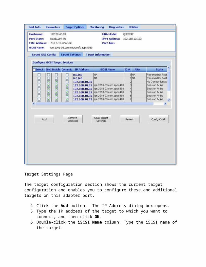
Health Monitoring – Enables or disables monitoring of the firmware and adapter. When this option is enabled, the driver checks to ensure normal operation and quick recovery.
NOTE: QLogic recommends keeping this parameter enabled at all times.
To change this setting, click the down arrow and select the desired option from the drop-down list:
Off - Disables this featureOn - Enables this feature
LSO V2 IPv4 – Enables or disables Large Send Offload (LSO) of TCP over IPv4 packets. When this option is enabled, the TCP protocol stack in the host sends to the driver packets that are larger than maximum segment size (MSS), but less than or equal to 128K. The adapter segments the packets to multiple MSS-sized TCP segments. This can significantly reduce the effort required by the stack to segment data to be sent, which increases available CPU bandwidth. This offload method is also called Giant Segment Offload (GSO).
To change this setting, click the down arrow and select the desired option from the drop-down list:
Off - Disables this featureOn - Enables this feature
LSO V2 IPv6 – Enables and disables TCP large send offload of TCP over IPv6 packets. This parameter is similar to Large Send Offload V2 IPv4, except that the TCP packet to be sent uses the IPv6 protocol.
To change this setting, click the down arrow and select the desired option from the drop-down list:
Off - Disables this featureOn - Enables this feature
Completion Queue Size – Specifies the size for the ring where the system posts transmit completion and receive status indicators. Increase this value if the system experiences a significant performance decrease on either the transmit or receive side.
To change this setting, click the down arrow and select the desired value from the drop-down list:
10242048

409681921638432768
Interrupt Moderation – Enables or disables coalescing of interrupts. If this option is disabled, the CPU is interrupted once for every packet that is transmitted or received. If this option is enabled, the CPU is interrupted less often, which can increase available CPU bandwidth.
To change this setting, click the down arrow and select the desired option from the drop-down list:
Off - Disables this featureOn - Enables this feature
RSS Enable – Enables or disables dynamic load balancing across multiple CPUs, also known as Receive Side Scaling (RSS).
To change this setting, click the down arrow and select the desired option from the drop-down list:
Off - Disables this featureOn - Enables this feature
RSS Ring – Specifies the number of Receive Side Scaling (RSS) rings to use.
To change this setting, click the down arrow and select the desired number from the drop-down list:
1234
5. When you are finished making changes, click Save to save any changes to the adapter advanced parameters. The Security Check dialog box may display. In the Enter Password box, type the password, and then click OK. See Security Check.
The saved configuration overwrites any previous settings for the current adapter.
See Also
Viewing NIC Port Information Setting General NIC Port Parameters Viewing and Updating NIC Port Statistics

Performing NIC Port Diagnostics Viewing NIC Port VPD Information Partitioning NIC Ports
Viewing and Updating NIC Port Statistics
The NIC port's Statistics page lets you view NIC port statistics, which provide information about packets sent and received over the selected NIC port.
This topic provides steps for:
Viewing NIC port statistics Resetting NIC port statistics Setting the Sampling Rate for NIC Port Monitoring
Viewing NIC Port Statistics
To view statistical information about an NIC port:
1. In the QConvergeConsole system tree, expand a QLE324x or QLE82xx adapter node to display its ports.
2. Expand the Port, and then select the NIC port beneath it.3. Click the Statistics tab to open the Statistics page (see the illustration below).

NIC Port Statistics Page
The NIC port identifying information includes:
Hostname – The name or IP address of the host connected to the adapter. HBA Model – The QLogic adapter model. Port State – Adapter port state. IPv4 Address – IP address of the selected host server when configured using the IPv4
protocol. MAC Address – Media Access Control (MAC) address hard-coded to the port. Port Alias – NIC port alias name. This is the symbolic name you assign to the NIC port
for identification purposes. Subnet Mask – This value identifies the subnet in which the host server resides. For
example, if the selected host has an IP address of 172.17.141.6 and the subnet mask is 255.255.255.0, the communications protocols understand that all servers with the IP address of 172.17.141.x are connected within the same subnet.

Gateway – IP address of the server used to provide Internet access for the selected adapter.
IPv6 Address – IP address of the selected host server when configured using the IPv6 protocol.
Resetting NIC Port Statistics
When an NIC adapter resets, the NIC port statistics counters reset to their initial values of zero. When an NIC adapter refreshes, the NIC port statistics counters update.
Use the statistics drop-down menu to choose display options, shown in the following example.
NIC Port Statistics Options
To start recording statistics, click Start. To stop recording statistics, click Stop. To reset the statistics counters to zero, select Baseline from the drop-down menu and
click Clear Baseline. To display absolute counts of packets sent and received over the selected NIC port, select
Absolute from the drop-down menu. To view the rate by second, select Rate (per second) from the drop-down menu.
Setting the Sampling Rate for NIC Port Monitoring
You can set the adapter port monitor to automatically update at a given rate, between 5 and 30 seconds, by setting the statistics sampling rate.
NOTE: The faster the statistics sampling rate, the more quickly the QConvergeConsole receives data from the host. However, faster statistics sampling rates consume more of your system's CPU and network resources and slows the system.
To set the statistics sampling rate for NIC port monitoring:
1. Click Set Rate in the Monitoring page. The Set Rate dialog box appears, as shown in the following example.
Set Rate Dialog Box

2. In the Set Rate field, use the up and down arrow keys to scroll to the desired sampling rate interval. The smaller the number you choose, the faster the sampling rate.The range is 5 to 30 seconds. The default is 5 seconds.
3. Click OK to set the sampling rate. 4. Click Start to commence collecting data at the statistics sampling rate. When you finish
collecting data, click Stop to end the data collecting session.
See Also
Viewing NIC Port Information Setting General NIC Port Parameters Setting Advanced NIC Port Parameters Performing NIC Port Diagnostics Viewing NIC Port VPD Information Partitioning NIC Ports
Performing NIC Port Diagnostics
NOTE: This NIC port Diagnostics page applies to NIC ports only for QLE324x and QLE82xx Converged Network Adapters. For QLE81xx adapters, see Performing Diagnostics.
To run diagnostics on a NIC port:
1. Select a QLE324x or QLE82xx adapter NIC port from the QConvergeConsole system tree.
2. Select the Diagnostics tab. The Diagnostics page opens, as shown in the following example.
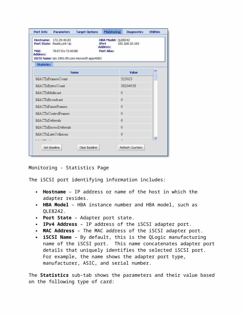
NIC Port Diagnostics Page
3. Select one or more diagnostic tests to run:
Hardware Test– Verifies that the hardware is running. Register Test – Verifies the NIC register read and write. Interrupt Test – Enables and disables the interrupt and functional verification
tests. Link Test – Verifies link activity. LED Test – Verifies that LEDs are on or off.
4. Click Run Tests. The system runs each test, starting from the first selected test on the list. The Diagnostics - General page displays the test progress in the Status column. Possible status results include:
In Progress Passed Failed
After completing all test, the system displays a dialog box, asking if you want to reboot the host.
See Also
Viewing NIC Port Information Setting General NIC Port Parameters

Setting Advanced NIC Port Parameters Viewing and Updating NIC Port Statistics Viewing NIC Port VPD Information Partitioning NIC Ports
Viewing NIC Port VPD Information
NOTE: This NIC port VPD page applies to NIC ports only for QLE324x and QLE82xx Converged Network Adapters. For QLE81xx adapters, see Viewing Fibre Channel and FCoE Port VPD Information.
To view VPD (Vital Product Data) information about an adapter port:
1. Select a QLE324x or QLE82xx adapter NIC port from the QConvergeConsole system tree.
2. Select the VPD tab. The VPD page opens, as shown in the following example.
QLE82xx NIC Port VPD Page
Located at the top of the page, the identifying information shows:
Hostname – The name or IP address of the host connected to the adapter. HBA Model – The QLogic adapter model. Port State – Adapter port state. IPv4 Address – IP address of the selected host server when configured using the IPv4
protocol.

MAC Address – Media Access Control (MAC) address hard-coded to the port. Port Alias – NIC port alias name. This is the symbolic name you assign to the NIC port
for identification purposes. Subnet Mask – This value identifies the subnet in which the host server resides. For
example, if the selected host has an IP address of 172.17.141.6 and the subnet mask is 255.255.255.0, the communications protocols understand that all servers with the IP address of 172.17.141.x are connected within the same subnet.
Gateway – IP address of the server used to provide Internet access for the selected adapter.
IPv6 Address – IP address of the selected host server when configured using the IPv6 protocol.
The information specific to the Port Vital Product Data (VPD) displays:
Product Identifier – Product identifier of the adapter. Part Number – Part number of the adapter. Serial Number – Serial number of the adapter. Engineering Date Code – Date code engineering uses to identify release information on
the NIC port. Flash Image Version – Multiflash image version installed on the NIC port.
See Also
Viewing NIC Port Information Setting General NIC Port Parameters Setting Advanced NIC Port Parameters Viewing and Updating NIC Port Statistics Performing NIC Port Diagnostics Partitioning NIC Ports
Home > Managing Ethernet (NIC) Ports > Partitioning NIC Ports
Partitioning NIC Ports
NIC partitioning (NPAR) is a feature built into QLE82xx Converged Network Adapters that divides the adapter's physical 10GbE ports into multiple PCIe physical functions. Each of the PCIe functions appear as an independent Ethernet interface to the host operating system. For example, a dual-port 10Gb adapter configured as an Ethernet-only adapter provides eight Ethernet functions – four for each physical port.
You can use the QConvergeConsole to configure and manage NPAR functions for both physical ports through NIC Partitioning tabs, available only on Port 1. You can enable or disable NPAR on either physical port and must reboot the operating system to apply the changes. When

NPAR is enabled, each physical port divides its function between four virtual ports, which support one of the following function types: NIC, FCoE, or iSCSI.
You can also manage Quality of Service (QoS) for traffic sent and received over each of the virtual ports. This feature lets you allocate minimum and maximum bandwidth to each virtual port.
You can configure up to four physical functions (seen as virtual ports) for each physical port. Each physical port can have up to 1 FCoE and 1 iSCSI physical functions. As an alternative, you can configure all four virtual ports as NIC ports (with Ethernet functions).
NOTE: The NIC Partitioning page applies to NIC ports only for NPAR-enabled Qxx82xx Converged Network Adapters.
To view the NIC Partitioning page:
1. Expand a QLE82xx adapter in the QConvergeConsole system tree.2. Expand the physical Port 1 node and select the NIC port. The content pane displays two
additional tabs that are not available on NIC ports for physical Port 2.3. Select the NIC Partitioning tab, as shown in the following example.
Selecting NIC Partitioning Tab
Located at the top of the page, the identifying information shows:
Hostname – The name or IP address of the host connected to the adapter. HBA Model – The QLogic adapter model.
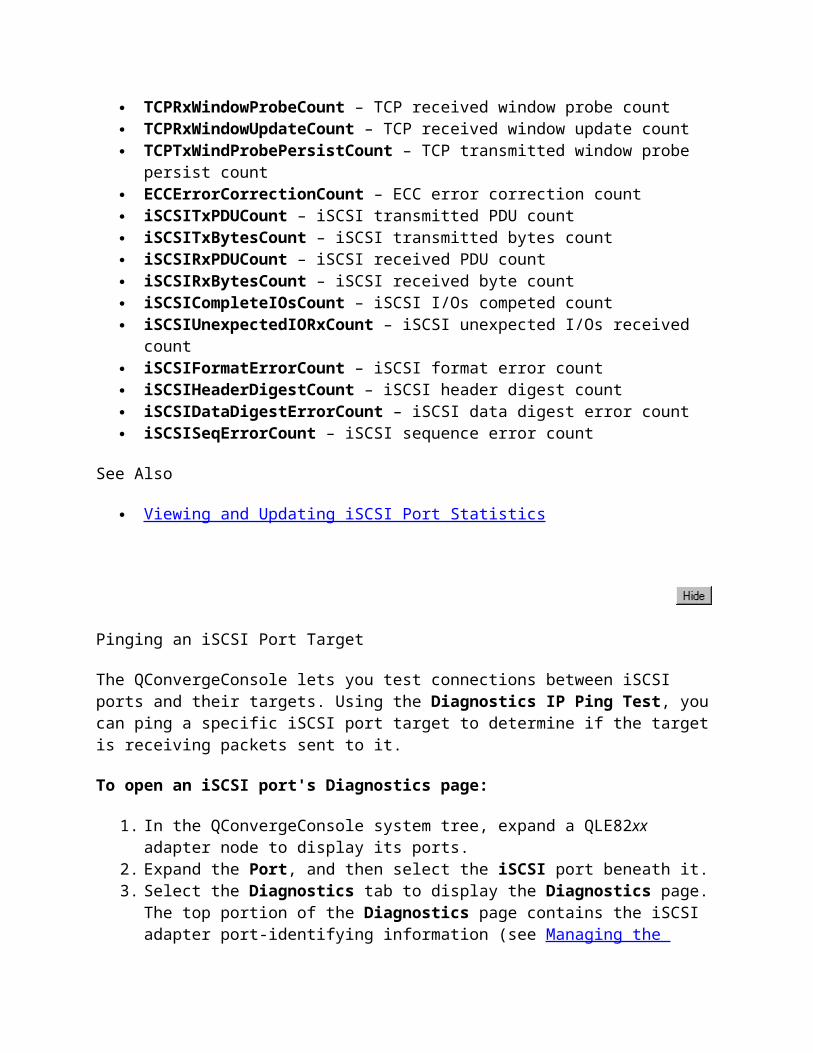
Port State – Adapter port state. IPv4 Address – IP address of the selected host server when configured using the IPv4
protocol. MAC Address – Media Access Control (MAC) address hard-coded to the port. Port Alias – NIC port alias name. This is the symbolic name you assign to the NIC port
for identification purposes. Subnet Mask – This value identifies the subnet in which the host server resides. For
example, if the selected host has an IP address of 172.17.141.6 and the subnet mask is 255.255.255.0, the communications protocols understand that all servers with the IP address of 172.17.141.x are connected within the same subnet.
Gateway – IP address of the server used to provide Internet access for the selected adapter.
IPv6 Address – IP address of the selected host server when configured using the IPv6 protocol.
See Also
Configuring Virtual Ports Setting Quality of Service (QoS) Viewing eSwitch Configuration
Home > Managing Ethernet (NIC) Ports > Partitioning NIC Ports > Configuring Virtual Ports
Configuring Virtual Ports
You can use the QConvergeConsole to configure and manage NPAR functions for both physical ports through NIC Partitioning tabs, available only on Port 1. You can enable or disable NPAR on either physical port and must reboot the operating system to apply the changes. When NPAR is enabled, each physical port divides its function between four virtual ports, configured to support one of the following function types: NIC, FCoE, or iSCSI. The QConvergeConsole represents each function type as a personality.
For diagrams that show the default NPAR settings, as well as the possible configurations, click the following:
NPAR Default Configuration NIC, FCoE, iSCSI NPAR Configuration Options - Personalities
NPAR Function Configuration
The following table shows the port identifications and the possible NPAR configurations.
Function Number Function Type Physical Port Number
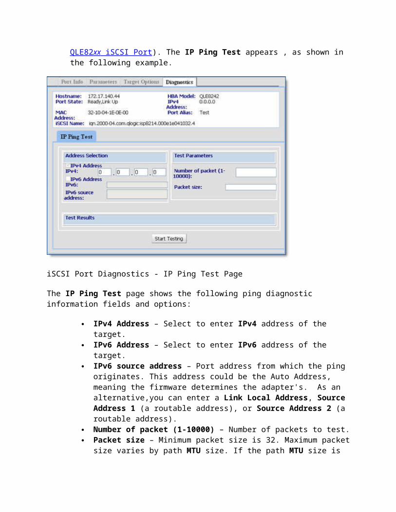
User Label1 System Number2
0 NIC 1 01 NIC 2 12 NIC 1 03 NIC 2 14 iSCSI/NIC 1 05 iSCSI/NIC 2 16 FCoE/NIC 1 07 FCoE/NIC 2 1
1The physical port number is displayed as Port 1 or Port 2 on the adapter port's label and in the QConvergeConsole's system tree.
2The physical port number is displayed as Phy Port 0 or Phy Port 1 on the NPAR Configuration screen.
NOTEs
Functions 0 and 1 are always enabled as NIC personalities, one for the first port and one for the second port; you can disable any of the other functions.
NIC, iSCSI, and FCoE have fixed function numbers. Functions 2 and 3 can only be NIC personalities. Functions 4 and 5 can be iSCSI or NIC personalities. Functions 6 and 7 can be FCoE or NIC personalities. You can configure only one iSCSI and one FCoE personalities for each physical port.
To configure virtual ports:
1. Expand a QLE82xx adapter in the QConvergeConsole system tree.2. Expand the physical Port 1 node and select the NIC port. The content pane displays two
additional tabs that are not available on NIC ports for physical Port 2.3. Select the NIC Partitioning tab. The NIC Partitioning Configuration page displays
configuration details that apply to the selected NPAR configuration and personality options, as shown in the following example.

NIC Partitioning Configuration Page
4. Select the physical port you want to configure from the Physical Port drop-down list. 5. If you want to change its function type, select the NIC partition and select the desired
protocol from the Function Type drop-down list. 6. Click Save to save any changes. The Security Check dialog box may display. In the
Enter Password box, type the password, and then click OK. See Security Check. 7. Reboot the operating system to apply the changes.
See Also
Partitioning NIC Ports Setting Quality of Service (QoS) Viewing eSwitch Configuration
Setting Quality of Service (QoS)
Each physical port on a QLE82xx Converged Network Adapter can send and receive data up to 10Gbps in both directions at the same time. When the physical port is partitioned into four virtual ports, the port bandwidth is divided between the virtual ports according to traffic demands.

The QConvergeConsole lets you set Quality of Server (QoS) for each virtual port by setting minimum and maximum percentages of the physical port's bandwidth for each virtual port. Using this feature lets you guarantee a transmission rate for each port that requires a particular bandwidth to run mission-critical applications for business continuity using virtual ports. The setting for a given QoS can resolve bottlenecks that exist when Virtual Machines contend for port bandwidth.
To set the Quality of Service (QoS):
1. Expand a QLE82xx adapter in the QConvergeConsole system tree.2. Expand the physical Port 1 node and select the NIC port. The content pane displays two
additional tabs that are not available on NIC ports for physical Port 2.3. Select the NIC Partitioning tab, and then click the Management sub-tab. The NIC
Partitioning Management General page displays configuration details that apply to the selected NPAR, as shown in the following example.
NIC Partitioning - General Management Page
4. Click the down arrow and select the NIC partition (NPAR0, NPAR1, NPAR2, or NPAR3) from the drop-down list.
Information and configuration fields related to the selected NIC partition include:

Default MAC Address – The Media Access Control (MAC) address set at the manufacturer.
Location – The logical location in the system: PCI bus number, device number, and function number.
NPAR PCI Function Number – The function number (0, 1, 2, 3, 4, 5, 6, or 7) of the eight PCIe function numbers claimed by the adapter.
NPAR Function Type – This correlates to the personality of the selected NPAR (PCIe) function: NIC, iSCSI, or FCoE
Minimum Bandwidth (%) – Use the up and down arrows to scroll between 1% to 100% to set the bandwidth you want to guarantee for data sent and received over the selected virtual port. Each additional percent increments the bandwidth by 100 MBps. For example, setting the minimum bandwidth to five percent guarantees sending and receiving data over the selected port at 500 MBps.
Maximum Bandwidth (%) – Use the up and down arrows to scroll between 1 to 100% to set the maximum bandwidth you want to allow for data sent and received over the selected virtual port. Each additional percent increments the bandwidth by 100 MBps. For example, setting the minimum bandwidth to 100 percent allows for sending and receiving data over the selected port at 10,000 MBps.
5. Repeat the previous step to configure the minimum and maximum bandwidth on the other virtual ports.
6. When you are finished setting changes, click Save to save any changes to the adapter advanced parameters. The Security Check dialog box may display. In the Enter Password box, type the password, and then click OK. See Security Check.
See Also
Partitioning NIC Ports Configuring Virtual Ports Viewing eSwitch Configuration
Home > Managing Ethernet (NIC) Ports > Partitioning NIC Ports > Viewing eSwitch Configuration
Viewing eSwitch Configuration
The QLE82xx Converged Network Adapters provide eSwitch (embedded switch) functionality. This provides a basic VLAN aware Layer-2 switch for Ethernet frames. Each physical port has one instance of eSwitch, which supports all NPARs on that physical port.
NOTE: The eSwitch Management page applies only to adapters installed on Xen Servers. QConvergeConsole does not let you edit this information. Configuring this information requires an API application. For example, VMware® vSphere™ provides a common information model (CIM) monitoring framework for both classic ESX and ESXi.

The QConvergeConsole displays the current eSwitch properties and capabilities. The eSwitch configuration is persistent across reboots on the server.
The eSwitch also supports a mirroring capability to replicate traffic on one or more NPARs running in privileged mode. Port mirroring is intended primarily for debugging; therefore, the port mirroring settings are not preserved across reboots.
To view the eSwitch configuration:
1. Expand a QLE82xx adapter in the QConvergeConsole system tree.2. Expand the physical Port 1 node and select the NIC port. The content pane displays two
additional tabs that are not available on NIC ports for physical Port 2.3. Select the NIC Partitioning tab, and then click the Management sub-tab. 4. Select the eSwitch sub-tab. The NIC Partitioning eSwitch Management page displays
configuration details that apply to the port's eSwitch configuration settings, as shown in the following example.
NIC Partitioning - eSwitch Management Page
If the eSwitch has been configured for NPAR functions, the NIC Partition eSwitch Configuration section provides the following information about the eSwitch for the selected NIC port. A check mark appears in check boxes for enabled options.
ESwitch Instance Number – Corresponds to the system's physical port number.

VLAN ID – Identification number assigned to the VLAN. Active VLAN Count – The number of VLANs created on the eSwitch function. Active Unicast filters count – The number of Unicast filters enabled on a given MAC
device. Ability to change operating MAC Address – Shows whether the MAC address can be
edited. Replication of Tx multicast packets to NPAR – When this option is enabled, if
function 0 is receiving any traffic, Tx multicast packets can increment in functions 2,4, and 6.
Replication of Rx multicast packets to NPAR – When this option is enabled, if function 0 is receiving any traffic, Rx multicast packets can increment in functions 2,4, and 6.
VLAN Filtering – Shows whether eSwitch can filter VLANs tagged in host. Capability to Enable Promiscuous Mode – Shows whether the eSwitch can accept
everything. VLAN ID Stripping – Shows whether the eSwitch can strip VLAN IDs. VLAN Tagged packets from host – Shows whether the eSwitch can accept the packets
tagged in host with any VLAN ID.
See Also
Partitioning NIC Ports Configuring Virtual Ports Setting Quality of Service (QoS)
Home > Troubleshooting
Troubleshooting
The following topics describe how to resolve the problems that can occur when installing and using the QConvergeConsole:
Troubleshooting Tools – Describes the tools that can help you identify the source of a hardware or software problem.
Tracing QConvergeConsole GUI and Agent Activity (Debug) – Provides procedures for enabling trace to debug problems as directed by your authorized service provider.
NOTE: The qlremote agent refers to the QConvergeConsole server agent (QConvergeConsole FC Windows XP Professional, Windows 2000, Windows Server 2003, Windows Vista, and Windows Server 2008 agent, QConvergeConsole FC Linux agent, QConvergeConsole FC Solaris agent, QConvergeConsole FC NetWare 5/6.x agent, or QConvergeConsole FC Mac OS X agent) with which the QConvergeConsole GUI (client) connects to manage QLogic QLA2xxx Fibre Channel adapters.

Troubleshooting Tools
When you encounter hardware problems, use the tools described in the following topics:
Windows Event Log Linux Messages File Solaris Messages File
Windows Event Log
The Windows event log is the main source of information for device driver problems and events. Device drivers usually indicate only status by logging events in the system event log.
The miniport driver logs events for significant driver errors. Because of a limitation of the Windows miniport driver interface, the miniport can log only two 32-bit values for any event. Information about interpreting these event codes is in the eventlog.txt file, which is shipped with the miniport driver.
In addition, the miniport driver can be configured to perform extended event logging for an adapter, which causes it to log all loop transitions and many minor events. Extended event logging uses extra overhead and is enabled only in troubleshooting situations. The extended event logging flag is stored in the adapter parameters and can be modified using Fast!UTIL.
Linux Messages File
For Red Hat/SuSE Linux systems, the Linux messages file is the main source of information for device driver problems and events. Device drivers usually indicate only status by logging events in the Linux messages file. QConvergeConsole agents also use the Linux messages file to report service errors, etc.
The Linux agent logs events for significant driver errors. In addition, the Linux agent can be configured to perform extended event logging for an adapter, which causes it to log all loop transitions and many minor events. Extended event logging uses extra overhead and is enabled only in troubleshooting situations. The extended event logging flag is stored in the adapter parameters and can be modified using Fast!UTIL.
The path for the linux messages file is:
/var/log/messages
Solaris Messages File
For Solaris SPARC/x86 systems, the Solaris messages file is the main source of information for device driver problems and events. Device drivers usually indicate only status by logging events

in the Solaris messages file. QConvergeConsole agents also use the Solaris messages file to report service errors, etc.
The Solaris agent logs events for significant driver errors. In addition, the Solaris agent can be configured to perform extended event logging for an adapter, which causes it to log all loop transitions and many minor events. Extended event logging uses extra overhead and is enabled only in troubleshooting situations. The extended event logging flag is stored in the adapter parameters and can be modified using Fast!UTIL (Solaris SPARC), FCode (Solaris x86), or QConvergeConsole.
The path for the Solaris messages file is
/var/adm/messages
Tracing QConvergeConsole GUI and Agent Activity (Debug)
Additional information, obtained from tracing the QConvergeConsole GUI and agent activity, can help troubleshoot application problems. Once debug has been enabled following the steps in this section, as directed by your authorized service provider, attempt to reproduce the problem to capture the application GUI and agent activity.
This section discusses:
Tracing QConvergeConsole GUI Activity Exporting or Saving Agent Activity Logs
Tracing QConvergeConsole GUI Activity
To trace QConvergeConsole GUI activity:
1. Shut down QConvergeConsole application. 2. Edit the local.properties file, which is located where QConvergeConsole is installed.
Change the following properties:node.trace.level=900 node.trace.output.setlevelonly=false
3. Edit the agent.properties file, which is located where QConvergeConsole is installed. Change the following property:node.agent.quiet.mode.enable=0
See the illustrations below for examples.

local.properties File (Example)
agent.properties File (Example)
4. Edit the QConvergeConsole.lax file, which is located where QConvergeConsole is installed. Do one of the following:
NOTE: You just hold the CTRL key down and bring up the application also at the same time bring up the console viewer to see the messages. The levels can be set the same way by updating the local.properties file.
1.o Edit the file so that the information displays on the console. Change the following
properties: lax.stderr.redirect=consolelax.stdout.redirect=consolelax.stdin.redirect=console
1.

o Edit the file so that the information is saved to a file. For a Windows XP Professional/Windows 2000/Windows Server 2003/Windows Vista system, the location could be: lax.stderr.redirect=c:\\trace.txtlax.stdout.redirect=c:\\trace.txtlax.stdin.redirect=c:\\ trace.txt
1.o For a Red Hat/SuSE Linux or Solaris SPARC/x86 system, the location could be:
lax.stderr.redirect=/trace.txtlax.stdout.redirect=/trace.txtlax.stdin.redirect=/trace.txt
See the illustration below
5. If you are using a Windows XP Professional, Windows 2000, Windows Server 2003, Windows Vista, or Windows Server 2008 system, do the following to change the height of the screen buffer:
a. Click the Start button, point to Programs, point to Accessories, and click Command Prompt.
b. The Command Prompt window displays. Click the upper left corner of the title bar.
c. From the shortcut menu, click Properties. The "Command Prompt" Properties dialog box displays.

"Command Prompt" Properties Dialog Box
d. Click the Layout tab.e. In the Screen Buffer Size Height box, type 9999. Click OK.f. The Apply Properties to Shortcut dialog box displays. Click Modify
shortcut that started this window. Click OK.
6. Start the QConvergeConsole; a new console window that displays QConvergeConsole GUI activity opens.
7. When you finish tracing the GUI activity, save the trace to a file. See Exporting or Saving the Agent Logs.
Exporting or Saving Agent Activity Logs
This section discusses:
The agent logs Exporting or saving the agent logs

The Agent Logs
Agent activity automatically logs to one of the following. The name and location of the log differs, depending on the type of operating system.
Windows XP Professional, Windows 2000, Windows Server 2003, Windows Vista, and Windows Server 2008 – Event Viewer
Red Hat and SuSE Linux – var/log/messages Macintosh – Use the Utilities console application Solaris SPARC and Solaris x86 – /var/log/syslog NetWare – sys:\\etc\lremote.log
Saving the Agent Logs
Exporting or Saving the Agent Logs
You can save or export the agent log for reference when troubleshooting the QConvergeConsole.
Windows XP Professional, Windows 2000, Windows Server 2003, Windows Vista, or Windows Server 2008
To save the current application log from the Event Viewer:
1. Click the Start button, point to Programs, point to Administrative Tools, and click Event Viewer.
2. From the Log menu, click Save As. Save the file using an appropriate name.
Red Hat, SLES Linux, or Macintosh
To export agent activity:
1. Open a terminal (for example, xterm or eterm).2. Stop the currently running qlremote agent:
# killall -TERM qlremote
3. In the agent.properties file, add the following line:node.agent.quiet.mode.enable=0
4. Start the agent, again, without forking into the background. Redirect the stdout and stderr properties to a file.
5. Send the file to your authorized service provider.For Red Hat/SLES Linux: # /usr/local/bin/qlremote > / AgentOutput.txt 2>&1

For Macintosh: # /installation folder/qlremote > / AgentOutput.txt 2>&1
5. Open a second terminal to start the QConvergeConsole GUI. Connect to the host with the QConvergeConsole GUI.
6. From the terminal you opened in step 1, press CTRL+C to stop the qlremote agent. This causes the agent to clean up and terminate.
Solaris SPARC or Solaris x86
To export agent activity:
a. Open a terminal (for example, xterm, or dtterm).b. Do the following to stop the currently running qlremote agent:
a. Type the following and then press ENTER to determine the process identifier ( pid) of qlremote:# ps - ef | grep qlremoteThe pid displays, as in the following example. Note that in the example, the pid is 227.
b. Type the following and then press ENTER. pid is the identifier returned in step a.# kill -TERM pid
c. In the agent.properties file, add the following line:node.agent.quiet.mode.enable=1
4. Start the agent, again, without forking into the background. Redirect the stdout and stderr properties to a file. Send the file to your authorized service provider.# /installation folder/qlremote> / AgentOutput.txt 2>&1
5. Open a second terminal to start the QConvergeConsole GUI. Connect to the host with the QConvergeConsole GUI.
6. From the terminal you opened in step 1, press CTRL+C to stop the qlremote agent. This causes the agent to clean up and terminate.
NOTE: For a NetWare system, the qlremote.log is already exported.
Frequently Asked Questions

The table below lists some frequently asked questions (FAQs) about the QConvergeConsole. For additional FAQs and other information, visit the QLogic support Web site support.qlogic.com.
Frequently Asked Questions
Q: On what platforms does QConvergeConsole run?
A:
The QConvergeConsole TC/GUI runs on any platform that supports the Java JVM 1.6.21/22 specification. The agent runs only on Windows XP Professional, Windows Server 2003/R2, Windows Vista, Windows 7, Windows Server 2008/R2, Solaris SPARC, Solaris x86, Red Hat Linux, SuSE Linux, Macintosh OS X, and NetWare.
Q: Can a QConvergeConsole GUI running on Red Hat/SuSE Linux talk to a Windows host running the agent?
A:The QConvergeConsole GUI running on any platform can talk to any other platform running the agent. The QConvergeConsole GUI allows connections to different platforms at the same time.
Q: What does the blinking heart on the connected host mean?
A:
QConvergeConsole actively pings the agent at the specified broadcast interval. This allows QConvergeConsole to detect agent presence on all platforms (even if agent shutdown notification is not supported). It also allows the detection of agent crashes as soon as possible. During an agent crash, the notification may not have been sent to all the connected GUIs.
Q: Does QConvergeConsole support SNMP?
A: No, QConvergeConsole currently supports only the RPC communication layer between the GUI and agent.
Technical Support
Customers should contact their authorized maintenance provider for technical support of their QLogic adapter products. QLogic-direct customers may contact QLogic Technical Support; others will be redirected to their authorized maintenance provider.
Visit the QLogic support Web site listed in Contact Information below for the latest firmware and software updates.
Availability

QLogic Technical Support is available from 7:00 AM to 7:00 PM Central Standard Time, Monday through Friday, excluding QLogic-observed holidays.
Contact Information
Address:
QLogic Corporation4601 Dean Lakes Blvd.Shakopee, MN 55379USA
Telephone: +1 952-932-4040
E-mail:Technical Service
Technical Training [email protected]@qlogic.com
Adapter Support Web Site: http://solutions.qlogic.com
Contacting QLogic
For product information, our latest drivers, and links for technical assistance, please visit QLogic's Web site at: http://www.qlogic.com/CompanyInfo/Pages/ContactQLogic.aspx
Send comments and suggestions regarding the documentation of this product to [email protected].
