pyrolysis of whole wood chips and rods in a novel ablative
TRANSCRIPT

Fuel 194 (2017) 229–238
Contents lists available at ScienceDirect
Fuel
journal homepage: www.elsevier .com/locate / fuel
Full Length Article
Pyrolysis of whole wood chips and rods in a novel ablative reactor
http://dx.doi.org/10.1016/j.fuel.2017.01.0100016-2361/� 2017 Elsevier Ltd. All rights reserved.
⇑ Corresponding author.E-mail address: [email protected] (F.L.P. Resende).
Guanqun Luo a, Devin S. Chandler a, Luiz C.A. Anjos b, Ryan J. Eng a, Pei Jia c, Fernando L.P. Resende a,⇑a School of Environmental and Forest Sciences, University of Washington, Seattle, WA 98195, United StatesbDepartment of Chemical Engineering and Chemistry, Federal Institute of Education, Science and Technology, Recife, PE 50740-540, BrazilcDepartment of Mechanical Engineering, University of Washington, Seattle, WA 98195, United States
h i g h l i g h t s
� A novel lab-scale ablative pyrolysis reactor was designed and constructed.� Wood chips and a rod were directly converted into bio-oil via ablative pyrolysis.� Bio-oil yield from ablative pyrolysis of wood chips (20 mm) was 60 wt.%.� Results from ablative reactor were similar to those from a fluidized bed reactor.
a r t i c l e i n f o
Article history:Received 13 October 2016Received in revised form 30 December 2016Accepted 4 January 2017
Keywords:Fast pyrolysisAblative pyrolysis reactorBeetle-killed treesWood chipsBio-oil
a b s t r a c t
The ability to carry out pyrolysis of entire wood chips and rods instead of small particles would be ofgreat value for mobile pyrolysis units, because of the large possible savings in grinding costs (7–9% oftotal process costs). With this goal in mind, we designed and constructed a novel lab-scale ablative reac-tor for fast pyrolysis of entire wood chips and even wood rods, converting those directly into a high yieldof bio-oil for the first time. The bio-oil yield from fast pyrolysis of wood chips (10 � 20 mm) was as highas 60 wt.%, similar to that from wood crumbles (2 � 2 mm). Additionally, the yield and composition ofbio-oil from ablative pyrolysis were in the same range as those obtained from a fluidized bed reactorusing <1 mm particles, with the small differences (slightly lower yield and HHV, and higher water con-tent) attributed to the longer vapor residence times in the ablative reactor, which promote secondaryreactions. We modeled the heat transfer characteristics of this semi-batch system, and comparison withexperimental measurements confirmed that radiation from the hot components does not significantlydecompose the wood prior to direct contact with the hot metallic surface in ablative pyrolysis. The find-ings of this work have the potential to lead to new developments for small-scale, mobile pyrolysis unitsfor the disposal of forest residues.
� 2017 Elsevier Ltd. All rights reserved.
1. Introduction
Lignocellulosic biomass is an abundant renewable energyresource. The use of biomass for energy leads to carbon neutralprocesses, and the chemicals and fuels derived from it have atremendous potential to reduce the problems caused by ourdependence on fossil fuels [1]. Fast pyrolysis is a promising tech-nology to convert lignocellulosic biomass into liquid fuels or chem-icals, and it has been in development for over 30 years. In thisprocess, biomass is heated up to 400–600 �C at a very high heatingrate (�500 �C/s) in the absence of oxygen, whereby it decomposesinto organic vapors, solid char, and permanent gases [2,3]. Theorganic vapors are rapidly cooled down and condensed to a liquid
product, known as bio-oil, which is the main product of fast pyrol-ysis. Depending on the feedstock, the yield of bio-oil can exceed70 wt.% on dry basis [2,3]. Bio-oil can either be combusted in boil-ers, engines, and turbines to generate heat or power, or beupgraded to produce transportation fuels and commodity chemi-cals [2–5].
Fast pyrolysis has been extensively studied for different feed-stocks, including agricultural, woody, and algal biomass [6–9].Our previous study using Py-GC/MS-FID indicated that fast pyroly-sis is a promising way to dispose beetle-killed trees by convertingthem into high-value chemicals and fuels [10,11]. Once these treesare dead, they may fall without previous warning, representing athreat to public safety, and are also undesirable for the solid woodpanel manufacturing industry. To date, about 42 million acres offorests have been attacked by bark beetles in the western UnitedStates, and they are typically located far from the urban industrial

230 G. Luo et al. / Fuel 194 (2017) 229–238
areas [12]. Therefore, using a mobile pyrolysis unit to convertbeetle-killed trees near the harvesting point could significantlyreduce the transportation costs that are a key barrier to wide-spread utilization of this vast resource, since bio-oil has 6–8 timeshigher energy density than the green wood chips [13,14].
The reactor is the key component of the mobile pyrolysis sys-tem. Reactors for fast pyrolysis of biomass include the bubbling flu-idized bed reactor, circulating fluidized bed reactor, free-fallreactor, auger reactor, and ablative reactor. For most pyrolysisreactor configurations, the biomass feedstock needs to be groundinto small particles of around 2 mm or less, because the processrequires minimizing heat transfer resistances throughout the par-ticle [15]. Kumar estimated that the costs of biomass chipping andgrinding were about 7–9% of the overall production costs [16]. For-est Concepts also studied the effects of final wood particle size onthe total comminution energy cost for the optimized Crumbler�
machine, and found out that the comminution energy costincreases from nearly zero to up to $4.50 per US ton as the woodparticle size is reduced from 12 mm to 1–2 mm [17]. Fortunately,the ablative pyrolysis reactor provides an opportunity to use largepieces of wood instead of only small particles as feedstock, savingon grinding costs. In ablative pyrolysis, biomass undergoes meltingand/or sublimation reactions as it directly contacts a hot solid sur-face. There is a steep temperature gradient at the biomass surface,leading to the formation of a thin superficial layer of reacting solid[18,19]. The reacting layer moves at constant velocity towards theheart of the cold biomass. Therefore, the reactive process in theablative reactor takes place only at the superficial layer rather thanthe entire biomass particle, and reaction rates are not limited bythe heat transfer through the entire particle. For this reason, inprinciple there is no upper limit to the biomass particle size thatcan be processed. These characteristics have been speculated inthe past, but there were no experimental data to back up the claimthat fast pyrolysis of large pieces of wood is possible. The majordrawback of the ablative pyrolysis reactor is that it is mechanicallydriven and therefore more complex than other types of reactors. Inaddition, ablative pyrolysis is surface area controlled, so scaling upis difficult. However, for using an ablative pyrolysis reactor as amobile unit, the scale-up issue is less of a concern.
To date, only a few ablative pyrolysis reactors have been devel-oped. The first pioneering experiments with ablative pyrolysiswere reported by Diebold [20], who used an electrically heatedwire to cut pieces of wood. These experiments demonstrated thatbiomass could be rapidly pyrolyzed via ablation, producing a thinlayer of liquid that vaporizes. Lédé et al. did a fundamental studyon the ablation heat transfer with specific application to woodpyrolysis [19,21–23]. However, their experimental setup did notallow for overall product recovery for analytical study and massbalance calculation. Reed and Cowdery [24] designed and con-structed a ‘‘pyrolysis mill” based on the principles of a conven-tional grain mill. Liquid bio-oil yield of up to 48.6% (dry basis)was obtained. However, the particle size of their feedstock, pinesawdust, was only as high as 14 mesh (1.4 mm). The major prob-lem of this system was the slow escape of the pyrolysis vaporsfrom the reactor, lowering the yield of bio-oil. Later, Peacockeet al. [25] designed an ablative reactor system with four rotatingblades scraping a continuous feed of pine wood, and up to 67.7%of bio-oil yield on dry feed was reported. One limiting factor of thissetup was the difficult removal of the char formed on the reactorsurface. The char built up below the rotating blades can quicklyprevent the incoming particles from being ablated. The particlesize of the pine wood feedstock was 4.75–6.25 mm, which wasthe largest particle size reported for tests in this system. AstonUniversity has claimed that whole wood chips up to 50 mm canbe processed in their ablative reactor, but no experimental dataor details on the reactor design are available [26]. Recently, Paulsen
et al. [27] designed a micro ablative pyrolysis apparatus in order todevelop a robust wood particle pyrolysis model that accounts forboth transport and pyrolysis decomposition kinetics at high tem-peratures and high heating rates. In the reactor, pyrolysis of1 mm thick wood particle was conducted by direct ablation witha heated surface, and the subsequent changes of wood compositionwere characterized by the spatiotemporally resolved diffuse reflec-tance in situ spectroscopy. However, bio-oil was not collected oranalyzed in their work.
Thus, we herein designed and constructed a prototype lab-scaleablative reactor to convert entire wood chips and wood rods intohigh yield of bio-oil in a single step. The goal is to experimentallyverify if high yields of bio-oil can be obtained from large particlesvia ablative pyrolysis. To the best of our knowledge, our work is thefirst to report bio-oil production from fast pyrolysis of entire woodchips and wood rods. The results from the ablative reactor werecompared to those obtained using a lab-scale fluidized bed reactor.In addition, the effect of pre-heating in this semi-batch reactorprior to ablative pyrolysis of wood chips was evaluated using bothmodeling work and experimental measurements.
2. Ablative pyrolysis reactor and its operation
As shown in Fig. 1, the ablative reactor is composed of a cham-ber, which contains a spinning bowl where the wood chips can beplaced, and a hot plate at the top that can move down and applypressure against wood chips. Fast pyrolysis initiates as the hotplate contacts the wood chips, and a high flow rate of inert gasrapidly sweeps the generated vapors out of the chamber forcondensation.
2.1. Reactor description
The ablative pyrolysis reactor designed and constructed in thepresent work is shown in Fig. 1. This is a semi-batch system witha capacity of 500 g wood chips per run. The reactor chamber ismade of A240 304L stainless steel with an internal diameter of0.30 m and an internal height of 0.42 m. This chamber can be splitinto an upper chamber and lower chamber, which are connectedwith flanges. A static seal is created by a graphite gasket placedbetween the two flanges faces. The wood chip bowl made ofA240 304L stainless steel has an internal diameter of 0.21 m anda height of 0.09 m. In order to make the generated pyrolysis vaporsescape from the wood chip bowl quickly, 0.05 � 0.01 m rectangu-lar slots were made on the shell of the bowl. To prevent wood chipsfrom dropping out of the bowl from the slots, a 1 mm thick perfo-rated T304 liner with 1.6 mm holes on a 3.2 mm 60� triangularpitch was installed inside the shell. The wood chip bowl is drivenby a 3 HP SEW-EURODRIVE gear motor, providing a rotation speedup to 160 rpm. The lower chamber contains a gas inlet and a gasoutlet. To minimize the vapor residence time, the product vaporsescaped out of the chamber through a perforated tube that wasbent around the circumference of the bowl and connected to thegas outlet. The upper plate is driven by a piston connected to ahydraulic system, capable of moving vertically and applying amaximum pressure of 1.5 bar against the wood chips. The lowerand upper drive shafts housing on the reactor chamber containgraphalloy bushings to prevent leakages and ingress of air. Three1 kW Chromalox CIR cartridge heaters were inserted in the upperplate, and are capable of generating a heat flux of up to 105 W/m2 and heating the plate up to 700 �C. Furthermore, two band hea-ters (Chromalox HBT 120) were used to heat the reactor wall to aminimum temperature of 300 �C, minimizing the condensation ofpyrolysis vapors on the inner reactor wall. Each of the band heatershas a power of 2 kW. The temperatures of upper plate and reactor

Fig. 1. Ablative pyrolysis reactor.
G. Luo et al. / Fuel 194 (2017) 229–238 231
wall are measured and controlled by inbuilt type K thermocouplesthat are connected to Chromalox 1/4 DIN temperature controllers.To minimize the heat losses, the entire reactor chamber was insu-lated using two layers of 1.3 cm thick ceramic sheets and one layerof silica fabric wrap.
2.2. Reactor operation
Fig. 2 shows the schematic diagram of the system, including thereactor, condenser, gas meter, etc. Prior to the reaction, a specifiedamount of wood chips is loaded in the wood chip bowl. After seal-ing the reactor chamber, the upper plate and the reactor wall arepre-heated to the operating temperatures. During the pre-heatingtime, the upper plate is located at the highest position. The dis-tance between the upper plate and the wood chip bowl bottomat this point is about 0.23 m to minimize the slow pyrolysis of bio-
Fig. 2. Schematic diagram of th
mass caused by radiative heat transfer during the pre-heating time.Concurrently, room temperature N2 (carrier gas) is introduced intothe system from the gas inlet at the reactor wall. The flow rate ofN2 is controlled by an Aalborg GCF47 mass flow controller withan accuracy of ±1.5%. Once the upper plate and reactor wall reachthe operating temperatures, the motor begins to rotate the woodchip bowl, and the upper plate driven by the hydraulic systemstarts moving down toward the wood chips. Ablative contact ofthe hot upper plate with the wood chips initiates fast pyrolysis.The produced pyrolysis vapors are then carried by N2 and quicklyescape from the reactor chamber through the gas outlet enter anice-water cooled impinger, in which heavy fractions of the bio-oilare condensed and collected. The remaining vapors flow out ofthe top of the impinger and enter a counter-current double-pipecondenser from the bottom, in which 50/50 vol.% propylene gly-col/water is used as cooling fluid in the outer pipe, with an inlet
e ablative reactor system.

Fig. 3. Schematic diagram for radiation heat rate calculation.
Table 2Parameters used for simulation.
Symbol Physical meaning
qtotal Total heat rateqconv Convection heat rateqrad Radiation heat rate�hbowl Average convection coefficient
Abowl Area of the wood chip bowl bottom surfaceTN2 N2 carrier gas temperatureTwood Wood chips temperatureqplate Radiation heat rate from upper plateqwall Radiation heat rate from reactor walle Emissivity coefficient of A240 304L
232 G. Luo et al. / Fuel 194 (2017) 229–238
temperature of �10 �C. This stage collects the light (aqueous) frac-tion of bio-oil. The remaining cooled vapors and non-condensablegases flow through a Swagelok coalescing filter and a packedquartz wool fiber, which collect any residual aerosols and watervapors. In addition, a building vacuum was connected to the sys-tem to drive the pyrolysis vapors out of the reactor chamber. How-ever, the non-condensable gases are sent to the receiver tank andcannot be collected for further analysis with only building vacuuminstalled. Thus, a parallel GAST vacuum with a gas outlet wasinstalled for a few runs for gas quantification and overall mass bal-ance calculation, though this slightly decreased bio-oil yield (moredetails are discussed in Section 5.2). The specifications of both thebuilding vacuum and the GAST vacuum pump are summarized inTable 1. Solid char is left on the wood chip bowl.
3. Simulation of wood chips temperature during the pre-heating time
During the pre-heating time, the wood chips on the bowlexchanged heat with the upper plate, the reactor wall, and theN2 gas via conduction, convection, and radiation (Fig. 3). Sincethe wood chips did not directly contact the hot components ofthe reactor, we are neglecting conduction. Then the total heat ratecan be expressed as:
qtotal ¼ qconv þ qrad ð1Þwhere qconv and qrad are convection and radiation heat rates,respectively.
Employing Newton’s law of cooling,
qconv ¼ �hbowlAbowlðTN2 � TwoodÞ ð2Þwhere �hbowl is the average convection coefficient, Abowl is the area ofthe wood chip bowl bottom surface, and TN2 and Twood are the tem-perature of N2 carrier gas and wood chips, respectively.
The radiation heat that reaches the wood chips includes radia-tion components from the upper plate and reactor wall. Employingthe Stefan-Boltzmann law,
qrad ¼ qplate þ qwall ¼ erAplateF13 T4plate � T4
wood
� �
þ erAwallF23 T4wall � T4
wood
� �ð3Þ
where e is the emissivity coefficient of A240 304L stainless steelmaterial (e = 0.67) [28], r is the Stefan-Boltzmann constant(r = 5.67 � 10�8 W/m2 K4), Aplate and Awall are the surface area ofupper plate and reactor wall, Tplate and Twall are the temperaturesof the upper plate and reactor wall, and F13 and F23 are the view fac-tors. We note that Eq. (3) is based on a few assumptions about thenature of the surfaces exchanging heat: (a) the surfaces are opaque,(b) the surfaces are gray (e = a), and (c) the reflective component ofthe radiosity (total radiative energy leaving a surface) is small bycomparison with the emissive power of the surfaces, and it wasneglected. This last assumption was based on the results of prelim-inary calculations, and it greatly simplifies the analysis of this tran-sient problem.
Details of the energy balance for each component and the selec-tion and calculation of the parameters in Eqs. (2) and (3) areincluded in the supplementary material. The total heat transfer
Table 1Specifications of the building vacuum and GAST vacuum pump.
Building vacuum Vacuum pump
Power (W) 3.50 � 103 186.43Flow rate (m3/s) 8.02 � 10�4 6.61 � 10�4
Vacuum level (Pa) 7.45 � 104–8.47 � 104 8.47 � 104
rate to the wood chips can be expressed as a function of timeand Twood. In order to simulate the temperature profile of woodchips as a function of pre-heating time, a numerical integrationhas been employed, where the total time can be divided by a smalltime interval (Dt = 1 s). According to the energy balance within thetime interval, the temperature of biomass after each time intervalis given below:
Tiþ1wood ¼ Ti
wood þqitotalDt
mwoodCp;woodð4Þ
where Tiwood and Tiþ1
wood are the temperatures of wood chips at thebeginning and at the end of the time interval, respectively. mwood
is the mass of wood chips (mwood ¼ 50 g) and cp;wood is the heatcapacity of wood, which is also a function of Twood. The temperaturesof the upper plate and reactor wall, Tplate and Twall, are functions oftime and were evaluated using energy balances. Matlab was usedto do the simulation. All the parameters used for the simulationare summarized in Table 2.
4. Experimental
4.1. Feedstock
The feedstock used in this study was beetle-killed lodgepolepine (Pinus contorta) purchased from Forest Concepts, LLC. Thesetrees were standing dead trees for 2–4 years before harvesting
r Stefan-Boltzmann constantAplate Surface area of upper plateAwall Surface area of reactor wallTplate Upper plate temperatureTwall Reactor wall temperatureF13, F23 View factorsmwood Mass of wood chipscp;wood Wood heat capacityDt Time interval

G. Luo et al. / Fuel 194 (2017) 229–238 233
and had lost their needles. Prior to the experiment, the feedstockwas chipped, ground, and sieved into three different sizes:2 � 2 mm, 5 � 15 mm, and 10 � 20 mm. Moreover, a small woodrod sample (35 dia. � 200 mm) was used. All of these samplesare shown in Fig. 4. The composition of the feedstock is given inTable 3. Briefly, the proximate analysis was carried out usingTGA, the ultimately analysis was performed using an elementalanalyzer (Series II 2400, PerkinElmer), and the chemical composi-tion was measured according to the ‘‘Standard Biomass AnalyticalProcedures” developed by the National Renewable Energy Labora-tory [10,11].
4.2. Fast pyrolysis in the ablative reactor
The ablative pyrolysis reactor system described in Section 2 wasused to carry out the fast pyrolysis of wood chips. Except for thesmall wood rod (100 g), 50 g wood crumbles or chips were usedfor each run. All the experiments reported herein were conductedat a pyrolysis temperature (upper plate temperature) of 500 or550 �C with a reactor wall temperature of 300 �C. The applied pres-sure against the wood chips was 0.5 bar, the rotation speed of thewood chip bowl was 100 rpm, and the run time was 3 min. N2 wasused as carrier gas. The selection of N2 flow rate and vacuum suc-tion is discussed in Section 5.2. After pyrolysis, the char left on thewood chip bowl was collected and weighed to determine its yield.Before and after each experiment, the impinger, condenser, and fil-ter were weighed to calculate the total bio-oil yield. Non-condensable gases were quantified when a parallel vacuum pumpwas installed. The total volume of non-condensable gases wasequal to the difference of the final and initial gas meter readingsubtracted the total volume of N2 carrier gas. An average molecularweight was determined by GC/TCD-FID analysis. Assuming thenon-condensable gases as an ideal gas, the mass of gas producedwas then calculated using the ideal gas law.
4.3. Fast pyrolysis in the fluidized bed reactor
For comparison purposes, fast pyrolysis of beetle-killed lodge-pole pine samples was also carried out in a lab-scale continuousbubbling fluidized bed reactor (the most common reactor usedfor fast pyrolysis). The schematic diagram of the reactor is shownin Fig. 5. In this system, the beetle-killed lodgepole pine samplewas first ground and sieved to a particle size of <1 mm to ensurerapid heat transfer rates in the reactor. The biomass was thenplaced in the hopper. While the system was pre-heated, N2 wasused to purge any oxygen present in the system. When the systemreached 500 �C, biomass at a rate of 0.6 kg/h was fed into the reac-tor by the screw auger. The reactor is a straight tube with an innerdiameter of 0.038 m and a length of 0.9 m. 500 g alumina sand wasused as heating media. N2 with a flow rate of 30 SLPM was used ascarrier gas and the residence time of pyrolysis vapors in the reactorwas around 1 s. At the outlet of the reactor, a cyclone was used toseparate the char from the pyrolysis vapors at a temperature of
a b c
Fig. 4. Picture of biomass feedstock in the wood chip bowl. (a) 2 � 2 mmwood crumbles�
wood rod.
325 �C. Vapors then flowed through an impinger, three counter-current double-pipe condensers (at 5 �C), and a coalescing filterfor condensation. Non-condensable gases were collected at theend of the system using a gas sampling bag. The char and sandwere removed from the reactor and cyclone and weighed whenthey were cooled to room temperature. The mixture was thenburned in a muffle furnace at 600 �C for 6 h, and the residues wereweighed after cooling down for determination of char yield. Theyield of bio-oil and non-condensable gases were determined in asimilar way to what is reported for the ablative unit.
4.4. Product analysis
The bio-oil samples were used for analysis as collected, since nosolid char was observed. Prior to the analysis, all bio-oil sampleswere stored in a refrigerator.
The moisture content of bio-oil was determined using a Karl Fis-cher titrator (V20, Mettler Toledo). The test method followed theASTM E203 standard for water using Hydranal-composite 5 Kreagent.
GC/MS-FID (QP2010, Ultra, Shimadzu) was used to determinethe chemical composition of bio-oil using methanol as solvent.The separation of different compounds was achieved by a SHRXI-5MS capillary column (30 m � 0.25 mm I.D. � 0.25 lm film thick-ness). The GC inlet temperature was 300 �C, and the inlet split ratiowas 30:1. The oven temperature was programmed from 40 �C to300 �C with a ramp of 10 �C/min. The initial and final temperatureswere held for 4 and 5 min, respectively. Compounds in bio-oil wereidentified by mass spectra comparison with NIST 2010 library, andwere quantified by FID using external standards (43 compoundswere identified and quantified using 20 standards).
The elemental composition of bio-oil and biochar were mea-sured using an elemental analyzer (Series II 2400, PerkinElmer).
The collected non-condensable gases were analyzed using GC/TCD-FID with a SUPELCO 60/80 Carboxen-1000 packed column(4.6 m � 2.1 mm I.D. � 0.5 lm film thickness). Helium with a flowrate of 35 mL/min was used as carrier gas. The oven temperaturewas programed from 40 �C (5 min) to 225 �C (10 min) at a heatingrate of 20 �C/min. Standard curves were prepared from individualgas (i.e. N2, CH4, CO, and CO2) for quantification.
5. Results and discussion
5.1. Wood chips temperature during the pre-heating time
The ablative pyrolysis reactor we designed is a semi-batch reac-tor. Prior to heating up the system, wood chips are loaded on thewood chip bowl. Due to the radiation from the hot components,the temperature of the wood chips may increase as we pre-heatthe upper plate and reactor wall to the operating temperature.However, biomass has been reported to slowly decompose at about200 �C, which negatively affects bio-oil yield [29]. Thus, prior toablative pyrolysis, the temperature profile of the wood chips
d
0 50 100 mm
; (b) 5 � 15 mmwood chips; (c) 10 � 20 mmwood chips, and (d) 35 dia. � 200 mm

Table 3Composition of beetle-killed lodgepole pine feedstock [10,11].
Proximate analysis (wt.%)Moisture Ash Volatile Fixed carbon7.30 0.26 82.29 10.15
Ultimate analysis (wt.%)a
C H Oc N HHV (MJ/kg)d
49.62 6.37 43.29 0.44 20.34
Chemical composition (wt.%)a
Extractivesa Carbohydratesb Ligninb
5.48 61.18 28.84
a wt.% of oven dry wood.b wt.% of oven dry extractive-free wood.c O wt.% was measured with O-mode using an elemental analyzer (Series II 2400, PerkinElmer).d HHV (MJ/kg) = C% � 0.3578 + H% � 1.1356 + N% � 0.0594 � O% � 0.0854–0.974 [10].
Fig. 5. Schematic diagram of the fluidized bed reactor system.
234 G. Luo et al. / Fuel 194 (2017) 229–238
during pre-heating time in our system was evaluated and con-trolled to minimize the extent of slow pyrolysis before the run.
Fig. 6 is the graphical description of how the temperature of thewood chips varies with the pre-heating time, comparing simula-tion results with experimental measurements. As the temperaturesof the upper plate and the reactor wall increase, the temperature ofthe wood chips gradually increases. When the upper plate is at550 �C and the reactor wall is at 300 �C, the temperature of thewood chips is around 200 �C. This indicates that the extent of slowpyrolysis of wood chips during the pre-heating time in the semi-batch ablative reactor is small. The results derived from our calcu-lation are in agreement with the measurements.
5.2. Minimizing the vapor residence times
A short vapor residence time is necessary to achieve a high yieldof liquid bio-oil in fast pyrolysis. Long vapor residence times pro-mote secondary reactions of pyrolysis vapors, favoring gas andchar production [30,31]. In our ablative pyrolysis reactor, the N2
flow rate is an important parameter affecting the vapor residencetime. Thus, the effect of N2 flow rate on the product yield has beenstudied, and the results are shown in Table 4. All the experimentswere performed using 5 � 15 mm wood chips at 550 �C. As the N2
flow rate increased from 15 to 40 SLPM, the yield of bio-oil did not
appear to increase (41.6 wt.% compared to 43.0 wt.%), and the charyield only slightly decreased from 26.0 wt.% to 23.7 wt.%. The slightdifference may be due to relatively short vapor residence timewhen using higher flow rate, 40 SPLM. However, both conditionsstill showed low yields of bio-oil and high yields of char, indicatingthe occurrence of secondary reactions to a large extent due to thelong vapor residence time.
The use of vacuum in fast pyrolysis has been investigated byprevious works and showed advantages of shortening vapor resi-dence time and reducing occurrence and intensity of secondaryreactions, thereby improving bio-oil yield [32,33]. Thus, the build-ing vacuum (specifications provided in Table 1) was used in ourreactor system. The suction provided by the vacuum preventspyrolysis vapors from staying inside the reactor chamber anddirects them towards the reactor outlet, escaping the chamberquickly instead of circulating inside the chamber. Two experimentswere performed using the building vacuum with 15 SLPM N2 flowrate or without N2 flow rate. Both conditions increased bio-oilyield, and the utilization of building vacuum combined with 15SLPM N2 flow rate significantly increased bio-oil yield by morethan 10 wt.%, decreasing char yield by 6 wt.%. Therefore, N2 flowrate of 15 SLPM combined with building vacuum were selectedto use for the remaining experiments in this study. One disadvan-tage of using the building vacuum is that the non-condensable

Fig. 6. Temperature profile of the wood chips during pre-heating time (solid lines represent results from calculation; orange circle, blue triangle, and gray square representdata from measurements). (For interpretation of the references to colour in this figure legend, the reader is referred to the web version of this article.)
Table 4Product yield at different N2 flow rates and vacuum conditions.
N2 flow rate (SLPM) 15 40 15 0 15Vacuum condition No No B B B + P
Product yield (wt.%)Bio-oil 41.6 43.0 52.8 48.4 47.0Char 26.0 23.7 19.7 26.1 26.4Non-condensable gases NA NA NA NA 15.8
B: building vacuum; P: vacuum pump; NA: not available.
G. Luo et al. / Fuel 194 (2017) 229–238 235
gases could not be analyzed and quantified. In order to quantify thegas production and thereby calculate the total mass balance, a vac-uum pump with a gas outlet was installed in parallel in a singlerun. From this run, the bio-oil, char, and non-condensable gasesyields were 47 wt.%, 26 wt.%, and 15.8 wt.%, respectively. The totalmass balance was about 90 wt.%. The composition of non-condensable gases was analyzed in GC/TCD-FID, including38.5 wt.% of CO, 57.3 wt.% of CO2, and 4.2 wt.% of CH4. The rela-tively lower bio-oil yield and higher char yield resulted from thelonger residence time caused by weaker suction in the parallel vac-uum system. Additionally, the results from preliminary experi-ments indicated that cracking reactions of volatiles intopermanent gases were important at 550 �C, leading to about8 wt.% lower yields of bio-oil at 550 �C than at 500 �C. For this rea-son, we selected 500 �C as the temperature for the rest of theexperiments in this study.
5.3. Ablative pyrolysis of wood crumbles, chips, and rods
Feedstock particle size is one of the important parametersaffecting bio-oil yield in fast pyrolysis, and usually very small(1–2 mm) particles are required to provide rapid heating andachieve a high yield of bio-oil [15]. Shen et al. investigated theeffect of particle size on the fast pyrolysis of oil mallee woody bio-mass in a fluidized bed reactor, and they found that the bio-oilyield dramatically decreased by 12–14% as biomass particle sizeincreased from 0.3 mm to 1.5 mm [34]. Similar results were alsoobserved by Salehi et al. [35]. The novel ablative pyrolysis reactorwe designed and constructed in this study aims to convert entire
wood chips into a high yield of bio-oil. The wood samples with dif-ferent particle sizes (i.e. 2 � 2 mm wood crumbles, 5 � 15 mm and10 � 20 mm wood chips, and a 35 dia. � 200 mm wood rod) wereused as feedstocks to study the effect of particle size on the productyield and distribution. All these experiments were operated at apyrolysis temperature of 500 �C, with N2 carrier gas at a flow rateof 15 SLPM and with building vacuum suction. Fig. 7 shows theproduct yield as a function of particle size. Two replicateswere performed using 5 � 15 mm and 10 � 20 mm wood chips toobtain standard deviations for the yield of bio-oil (±1.4 wt.%) andchar (±0.9 wt.%), and the standard deviations obtained from10 � 20 mm were applied to the results from 2 � 2 mm woodcrumbles and 35 dia. � 200 mm wood rod. Considering thestandard deviations, there was no difference in yields betweenthe 2 � 2 mm crumbles and the 5 � 15 mm and 10 � 20 mm woodchips. The yields of bio-oil and char were about 60 wt.% and 18 wt.%, respectively. These results support the hypothesis that the sizeof the wood chips does not affect the ablative process [19]. Notehow this conclusion is in stark contrast with the literature reportsfor effects of particle size obtained in other types of reactors. Thesystem also successfully pyrolyzed an entire wood rod(35 dia. � 200 mm), though this case shows lower yield of bio-oil(47 wt.%) and higher yield (25 wt.%) of char than wood chips.When 50 g of wood crumbles/chips was loaded in the wood chipbowl, the resulting thickness was around 5 mm, whereas thethickness of the wood rod was 35 mm. Using the wood rod asfeedstock; therefore, possibly led to more char due to the poorthermal conductivity of the wood and char, lowering the bio-oilyield.
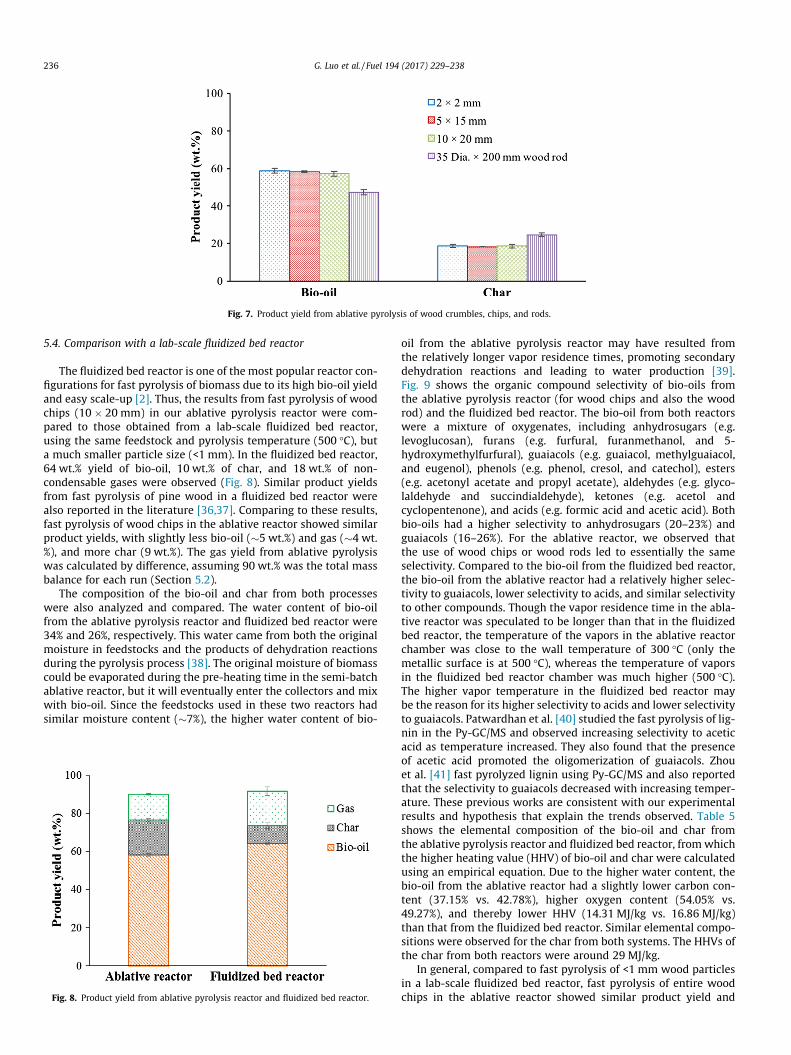
Fig. 7. Product yield from ablative pyrolysis of wood crumbles, chips, and rods.
236 G. Luo et al. / Fuel 194 (2017) 229–238
5.4. Comparison with a lab-scale fluidized bed reactor
The fluidized bed reactor is one of the most popular reactor con-figurations for fast pyrolysis of biomass due to its high bio-oil yieldand easy scale-up [2]. Thus, the results from fast pyrolysis of woodchips (10 � 20 mm) in our ablative pyrolysis reactor were com-pared to those obtained from a lab-scale fluidized bed reactor,using the same feedstock and pyrolysis temperature (500 �C), buta much smaller particle size (<1 mm). In the fluidized bed reactor,64 wt.% yield of bio-oil, 10 wt.% of char, and 18 wt.% of non-condensable gases were observed (Fig. 8). Similar product yieldsfrom fast pyrolysis of pine wood in a fluidized bed reactor werealso reported in the literature [36,37]. Comparing to these results,fast pyrolysis of wood chips in the ablative reactor showed similarproduct yields, with slightly less bio-oil (�5 wt.%) and gas (�4 wt.%), and more char (9 wt.%). The gas yield from ablative pyrolysiswas calculated by difference, assuming 90 wt.% was the total massbalance for each run (Section 5.2).
The composition of the bio-oil and char from both processeswere also analyzed and compared. The water content of bio-oilfrom the ablative pyrolysis reactor and fluidized bed reactor were34% and 26%, respectively. This water came from both the originalmoisture in feedstocks and the products of dehydration reactionsduring the pyrolysis process [38]. The original moisture of biomasscould be evaporated during the pre-heating time in the semi-batchablative reactor, but it will eventually enter the collectors and mixwith bio-oil. Since the feedstocks used in these two reactors hadsimilar moisture content (�7%), the higher water content of bio-
Fig. 8. Product yield from ablative pyrolysis reactor and fluidized bed reactor.
oil from the ablative pyrolysis reactor may have resulted fromthe relatively longer vapor residence times, promoting secondarydehydration reactions and leading to water production [39].Fig. 9 shows the organic compound selectivity of bio-oils fromthe ablative pyrolysis reactor (for wood chips and also the woodrod) and the fluidized bed reactor. The bio-oil from both reactorswere a mixture of oxygenates, including anhydrosugars (e.g.levoglucosan), furans (e.g. furfural, furanmethanol, and 5-hydroxymethylfurfural), guaiacols (e.g. guaiacol, methylguaiacol,and eugenol), phenols (e.g. phenol, cresol, and catechol), esters(e.g. acetonyl acetate and propyl acetate), aldehydes (e.g. glyco-laldehyde and succindialdehyde), ketones (e.g. acetol andcyclopentenone), and acids (e.g. formic acid and acetic acid). Bothbio-oils had a higher selectivity to anhydrosugars (20–23%) andguaiacols (16–26%). For the ablative reactor, we observed thatthe use of wood chips or wood rods led to essentially the sameselectivity. Compared to the bio-oil from the fluidized bed reactor,the bio-oil from the ablative reactor had a relatively higher selec-tivity to guaiacols, lower selectivity to acids, and similar selectivityto other compounds. Though the vapor residence time in the abla-tive reactor was speculated to be longer than that in the fluidizedbed reactor, the temperature of the vapors in the ablative reactorchamber was close to the wall temperature of 300 �C (only themetallic surface is at 500 �C), whereas the temperature of vaporsin the fluidized bed reactor chamber was much higher (500 �C).The higher vapor temperature in the fluidized bed reactor maybe the reason for its higher selectivity to acids and lower selectivityto guaiacols. Patwardhan et al. [40] studied the fast pyrolysis of lig-nin in the Py-GC/MS and observed increasing selectivity to aceticacid as temperature increased. They also found that the presenceof acetic acid promoted the oligomerization of guaiacols. Zhouet al. [41] fast pyrolyzed lignin using Py-GC/MS and also reportedthat the selectivity to guaiacols decreased with increasing temper-ature. These previous works are consistent with our experimentalresults and hypothesis that explain the trends observed. Table 5shows the elemental composition of the bio-oil and char fromthe ablative pyrolysis reactor and fluidized bed reactor, fromwhichthe higher heating value (HHV) of bio-oil and char were calculatedusing an empirical equation. Due to the higher water content, thebio-oil from the ablative reactor had a slightly lower carbon con-tent (37.15% vs. 42.78%), higher oxygen content (54.05% vs.49.27%), and thereby lower HHV (14.31 MJ/kg vs. 16.86 MJ/kg)than that from the fluidized bed reactor. Similar elemental compo-sitions were observed for the char from both systems. The HHVs ofthe char from both reactors were around 29 MJ/kg.
In general, compared to fast pyrolysis of <1 mm wood particlesin a lab-scale fluidized bed reactor, fast pyrolysis of entire woodchips in the ablative reactor showed similar product yield and

0
10
20
30
40
Acids
Ketones
Aldehyd
esEste
rs
Phenols
Guaiaco
ls
Furans
Anhydros
ug
Sele
ctiv
ity (%
)
Ablative reactor--wood chips
Ablative reactor--wood rod
Fluidized bed reactor
Fig. 9. Organic compound selectivity of bio-oil from ablative pyrolysis reactor and fluidized bed reactor.
Table 5Elemental composition of bio-oil and char from ablative pyrolysis reactor and fluidized bed reactor.
Elemental composition (wt.%) Bio-oil Char
Ablative Fluidized bed Ablative Fluidized bed
C 37.53 42.78 74.68 74.09H 8.38 7.92 3.41 4.41Oa 54.05 49.27 21.45 21.36N 0.03 0.03 0.17 0.14HHV(MJ/kg)b 14.31 16.86 28.52 29.81
a Calculate by difference.b HHV (MJ/kg) = (3.55 C2 � 232 C � 2230 H + 51.2 C H + 131 N + 20,600) � 10�3 [36].
G. Luo et al. / Fuel 194 (2017) 229–238 237
composition with a slightly lower bio-oil yield, a higher water con-tent, and a lower HHV of bio-oil. This is mainly caused by thelonger vapor residence times in the ablative reactor. The large reac-tor chamber volume, which was selected to minimize the slowpyrolysis of wood chips during the pre-heating time in this semi-batch reactor, was the main factor increasing the vapor residencetimes. However, this problem can be easily solved by modifyingthis prototype ablative pyrolysis reactor system into a continuoussystem in the future. It has been proposed many times that it ispossible to fast pyrolyze large pieces of wood in ablative reactors;however, the previously reported largest particle size used in abla-tive reactors to mainly produce bio-oil was only as high as 4.75–6.25 mm [19–23,25]. To the best of our knowledge, our study isthe first to report bio-oil production from fast pyrolysis of entirewood chips and wood rods, and the yield of bio-oil from woodchips (with size of up to 20 mm) was as high as 60 wt.%. The chop-ping/grinding costs would be significantly reduced by using woodchips as feedstock, which contribute to 7–9% of overall productioncosts. It is important to note that ablative pyrolysis is a processbased on the availability of a hot metallic surface area for con-tact/heat transfer, and for this reason its application in large-scale settings would be difficult. However, for small scale, mobilepyrolysis units intended for the disposal of forest residues, ablativepyrolysis of entire wood chips/logs is an interesting option, and thefindings of this work have the potential to lead to future develop-ments for this application.
6. Conclusion
A novel prototype lab-scale ablative fast pyrolysis reactor wasdesigned and constructed in this study to convert entire wood
chips and wood rods into bio-oil. Prior to ablative pyrolysis, thetemperature profile of wood chips during the pre-heating time inthis semi-batch reactor was evaluated and controlled to minimizethe extent of slow pyrolysis. The results from our calculations werein good agreement with experimental measurements and verifiedthat the extent of slow pyrolysis of wood chips during the pre-heating time was small in the ablative pyrolysis unit. The beetle-killed lodgepole pine wood samples with different particle sizes(i.e. 2 � 2 mm wood crumbles, 5 � 15 mm and 10 � 20 mm woodchips, and a 35 dia. � 200 mm wood rod) were used as feedstocks,and the results of this work confirm that the bio-oil yield fromablative pyrolysis is not dependent of the particle size in the rangestudied. Ablative pyrolysis of wood chips (10 � 20 mm) led to sim-ilar product yield as 2 � 2 mm wood crumbles, and the bio-oilyield was as high as 60 wt.%. These results were similar to thosefrom fast pyrolysis of small wood particles (<1 mm) in a fluidizedbed reactor. This study confirmed the hypothesis that high bio-oil yields can be obtained from ablative pyrolysis of entire woodchips. This information has the potential to save in grinding costsfor mobile pyrolysis units.
Acknowledgement
The authors would like to acknowledge the financial supportfrom USDA NIFA (Grant No. 2012-34638-2020). We would also liketo thank Forest Concepts for providing wood chips and wood rods,and Alaskan Copper Company for the detailed drawings, manufac-turing, and maintenance of the ablative reactor. We also thankJingda Wu from the University of Washington for his help on Mat-lab coding.
238 G. Luo et al. / Fuel 194 (2017) 229–238
Appendix A. Supplementary material
Supplementary data associated with this article can be found, inthe online version, at http://dx.doi.org/10.1016/j.fuel.2017.01.010.
References
[1] Ragauskas AJ, Williams CK, Davison BH, Britovsek G, Cairney J, Eckert CA, et al.The path forward for biofuels and biomaterials. Science 2006;311:484–9.
[2] Resende FLP. Reactor configurations and design parameters forthermochemical conversion of biomass into fuels, energy, and chemicals. In:Shi F, editor. Reactor and process design in sustainable energytechnology. Elesvier B.V.; 2014. p. 1–26 [chapter 1].
[3] Bianchi D, Perego C, Capuano F. Biomass transformation by thermo- andbiochemical process to diesel fuel intermediates. In: Cavani F, Albonetti S,Basile F, Gandini A, editors. Chemicals and fuels from bio-based buildingblocks. Germany: Wiley-Vch; 2016. p. 643–66 [chapter 2].
[4] Mortensen PM, Grunwaldt J-D, Jensen PA, Knudsen K, Jensen AD. A review ofcatalytic upgrading of bio-oil to engine fuels. Appl Catal, A 2011;407:1–19.
[5] Vispute TP, Zhang H, Sanna A, Xiao R, Huber GW. Renewable chemicalcommodity feedstocks from integrated catalytic processing of pyrolysis oils.Science 2010;330:1222–7.
[6] Ji-Lu Z. Bio-oil from fast pyrolysis of rice husk: yields and related propertiesand improvement of the pyrolysis system. J Anal Appl Pyrol 2007;80:30–5.
[7] Kim KH, Bai X, Rover M, Brown RC. The effect of low-concentration oxygen insweep gas during pyrolysis of red oak using a fluidized bed reactor. Fuel2014;124:49–56.
[8] Wang K, Brown RC, Homsy S, Martinez L, Sidhu SS. Fast pyrolysis of microalgaeremnants in a fluidized bed reactor for bio-oil and biochar production.Bioresour Technol 2013;127:494–9.
[9] Westerhof RJ, Brilman DWF, Garcia-Perez M, Wang Z, Oudenhoven SR, KerstenSR. Stepwise fast pyrolysis of pine wood. Energy Fuel 2012;26:7263–73.
[10] Luo G, Resende FL. Fast pyrolysis of beetle-killed trees. J Anal Appl Pyrol2014;110:100–7.
[11] Luo G, Resende FL. In-situ and ex-situ upgrading of pyrolysis vapors frombeetle-killed trees. Fuel 2016;166:367–75.
[12] USFS. Western Bark Beetle Strategy. U. S. Forest Service; 2011. <http://www.fs.usda.gov/Internet/FSE_DOCUMENTS/stelprdb5338089.pdf> [accessed on May20th, 2016].
[13] Badger PC, Fransham P. Use of mobile fast pyrolysis plants to densify biomassand reduce biomass handling costs—a preliminary assessment. BiomassBioenergy 2006;30:321–5.
[14] Raffelt K, Henrich E, Koegel A, Stahl R, Steinhardt J, Weirich F. The BTL2 processof biomass utilization entrained-flow gasification of pyrolyzed biomassslurries. Appl Biochem Biotech 2006;129:153–64.
[15] Bridgwater AV. Renewable fuels and chemicals by thermal processing ofbiomass. Chem Eng J 2003;91:87–102.
[16] Kumar A. A conceptual comparison of bioenergy options for using mountainpine beetle infested wood in Western Canada. Bioresour Technol2009;100:387–99.
[17] Forest concepts. Forest concepts completes US Department of Energy SBIRphase I Project to demonstrate technical feasibility of Milling Green and highmoisture biomass to biofuel feedstocks. Institution; 2014. <http://www.forestconcepts.com/index.php?page=04001> [accessed on May 20th,2016].
[18] Lédé J. Comparison of contact and radiant ablative pyrolysis of biomass. J AnalAppl Pyrol 2003;70:601–18.
[19] Lédé J, Panagopoulos J, Villermaux J. Experimental Measurement of ablationrate of wood pieces, undergoing fast pyrolysis by contact with a heated wall.In: Prepr Pap, Am Chem Soc, Div Fuel Chem, (United States); 1983, 38.
[20] Diebold J, Ablative pyrolysis of macroparticles of biomass. In: Proceedings ofthe specialists workshop on the fast pyrolysis of biomass, Copper MountainCo; 1980. p. 237.
[21] Lédé J, Li HZ, Villermaux J, Martin H. Fusion-like behaviour of wood pyrolysis. JAnal Appl Pyrol 1987;10:291–308.
[22] Lédé J, Panagopoulos J, Li HZ, Villermaux J. Fast pyrolysis of wood: directmeasurement and study of ablation rate. Fuel 1985;64:1514–20.
[23] Martin H, Lédé J, Li H, Villermaux J, Moyne C, Degiovanni A. Ablative melting ofa solid cylinder perpendicularly pressed against a heated wall. Int J Heat MassTransf 1986;29:1407–15.
[24] Reed TB, Cowdery CD. Heat flux requirements for fast pyrolysis and a newmethod for generating biomass vapor. In: 193rd National Meeting of theAmerican Chemical Society, American Chemical Society Division of PetroleumChemistry; 1987. p. 5–10.
[25] Peacocke G, Bridgwater A. Ablative plate pyrolysis of biomass for liquids.Biomass Bioenergy 1994;7:147–54.
[26] Aston University. <www.aston.ac.uk/EasySiteWeb/GatewayLink.aspx?alId=32782> [accessed on December 14th, 2016].
[27] Paulsen AD, Hough BR, Williams CL, Teixeira AR, Schwartz DT, Pfaendtner J,et al. Fast pyrolysis of wood for biofuels: spatiotemporally resolved diffusereflectance in situ spectroscopy of particles. ChemSusChem 2014;7:765–76.
[28] Bergman TL, Incropera FP, Lavine AS. Fundamentals of heat and masstransfer. John Wiley & Sons; 2011.
[29] Yang H, Yan R, Chen H, Lee DH, Zheng C. Characteristics of hemicellulose,cellulose and lignin pyrolysis. Fuel 2007;86:1781–8.
[30] Bridgwater A. Principles and practice of biomass fast pyrolysis processes forliquids. J Anal Appl Pyrol 1999;51:3–22.
[31] Bridgwater A, Meier D, Radlein D. An overview of fast pyrolysis of biomass. OrgGeochem 1999;30:1479–93.
[32] Benallal B, Roy C, Pakdel H, Chabot S, Poirier M. Characterization of pyrolyticlight naphtha from vacuum pyrolysis of used tyres comparison withpetroleum naphtha. Fuel 1995;74:1589–94.
[33] Roy C, Chaala A, Darmstadt H. The vacuum pyrolysis of used tires: end-uses foroil and carbon black products. J Anal Appl Pyrol 1999;51:201–21.
[34] Shen J, Wang X-S, Garcia-Perez M, Mourant D, Rhodes MJ, Li C-Z. Effects ofparticle size on the fast pyrolysis of oil mallee woody biomass. Fuel2009;88:1810–7.
[35] Salehi E, Abedi J, Harding T. Bio-oil from sawdust: effect of operatingparameters on the yield and quality of pyrolysis products. Energy Fuel2011;25:4145–54.
[36] Desisto WJ, Hill N, Beis SH, Mukkamala S, Joseph J, Baker C, et al. Fast pyrolysisof pine sawdust in a fluidized-bed reactor. Energy Fuel 2010;24:2642–51.
[37] Kang B-S, Lee KH, Park HJ, Park Y-K, Kim J-S. Fast pyrolysis of radiata pine in abench scale plant with a fluidized bed: influence of a char separation systemand reaction conditions on the production of bio-oil. J Anal Appl Pyrol2006;76:32–7.
[38] Oasmaa A, Czernik S. Fuel oil quality of biomass pyrolysis oils state of the artfor the end users. Energy Fuel 1999;13:914–21.
[39] Heo HS, Park HJ, Park Y-K, Ryu C, Suh DJ, Suh Y-W, et al. Bio-oil productionfrom fast pyrolysis of waste furniture sawdust in a fluidized bed. BioresourTechnol 2010;101:S91–6.
[40] Patwardhan PR, Brown RC, Shanks BH. Understanding the fast pyrolysis oflignin. ChemSusChem 2011;4:1629–36.
[41] Zhou S, Garcia-Perez M, Pecha B, Kersten SR, Mcdonald AG, Westerhof RJ.Effect of the fast pyrolysis temperature on the primary and secondary productsof lignin. Energy Fuel 2013;27:5867–77.