pxi switch modules product flyer - national instruments · maximum voltage maximum current maximum...
TRANSCRIPT

Have a question? Contact Us.
Page 1 | ni.com | PXI Switch Modules
PRODUCT FLYER
PXI Switch Modules CONTENTS PXI Matrix Switch Modules
PXI Multiplexer Switch Modules
PXI Relay Modules
PXI RF Matrix Switch Modules
PXI RF Multiplexer Switch Modules
PXI RF Relay Modules
SwitchBlock
PXI Relay Driver Modules
PXI Signal Insertion Switch Modules
PXI Transfer Switch Modules
PXI Programmable Resistor Modules
Platform-Based Approach to Test and Measurement
PXI Instrumentation
Hardware Services

Page 2 | ni.com | PXI Switch Modules
PXI Matrix Switch Modules PXI-2501, PXI-2503, PXI-2529, PXIe-2529, PXI-2530B, PXI-2531, PXIe-2531, PXI-2532B, PXIe-2532B, PXI-2533, PXI-2534, PXI-2535, PXI-2536, PXIe-2737, PXIe-2738, and PXIe-2739
• Software: Includes interactive soft front panel, API support for LabVIEW and text-based languages, shipping examples, and detailed help files
• Electromechanical, Reed, solid state, and FET relay options
• 1- and 2-wire options
• Up to 544 crosspoints in a single PXI slot
• Up to 150 V or 2 A
• Option for relay health monitoring through the NI Switch Health Center
Built for Automated Test and Measurement PXI Matrix Switch Modules are organized into rows and columns and provide maximum flexibility for switching systems by allowing you to connect any channel to any other channel. PXI Matrix Switch Modules use a variety of relay types, including electromechanical armature relays, reed relays, field-effect transistor (FET) relays, and solid-state relays, each with their own benefits, allowing you to choose a matrix that fits your requirements.
Additionally, NI switch modules offer advanced features, such as hardware triggering, relay health monitoring, onboard relay count tracking, and a wide variety of reconfigurable models, providing you the option to modify the topology of the switch based on your needs. These advanced features offer a smarter way to tackle difficult applications in industries ranging from consumer electronics to aerospace and defense.

Page 3 | ni.com | PXI Switch Modules
Table 1. NI offers a variety of PXI Matrix Switch Modules, varying in topology, density, relay type, and voltage/current rating, allowing you to pick the model that best fits your needs.
Maximum Voltage
Maximum Current
Maximum Bandwidth Relay Type Configuration(s)
PXI-2501 10 VDC 7 VAC 3 mA 400 kHz FET 4 x 6, 2-wire matrix
PXI-2503 60 VDC 30 VAC 1 A 10 MHz EMR 4 x 6, 2-wire matrix
PXI-2529 and PXIe-2529 150 V 2 A 10 MHz EMR 4 x 32, 2-wire matrix 8 x 16, 2-wire matrix Dual 4 x 16, 2-wire matrix
PXI-2530B 60 VDC 30 VAC 400 mA 19 MHz Reed
4 x 32, 1-wire matrix 8 x 16, 1-wire matrix 4 x 16, 2-wire matrix
PXI-2531 and PXIe-2531 60 VDC 30 VAC 500 mA 20 MHz Reed
4 x 128, 1-wire matrix 8 x 64, 1-wire matrix 2-bank, 4 x 64, 1-wire matrix 2-bank, 8 x 32, 1-wire matrix
PXI-2532B and PXIe-2532B
60 VDC 30 VAC 500 mA 20 MHz Reed
4 x 128, 1-wire matrix 8 x 64, 1-wire matrix 16 x 32, 1-wire matrix 2-bank, 4 x 64, 1-wire matrix 2-bank, 8 x 32, 1-wire matrix 2-bank, 16 x 16, 1-wire matrix 4-bank, 4 x 32, 1-wire matrix 16-bank, 2 x 16, 1-wire matrix 4 x 64, 2-wire matrix 8 x 32, 2-wire matrix 16 x 16, 2-wire matrix 2-bank, 4 x 32, 2-wire matrix
PXI-2533 55 VDC 30 VAC 1 A 1.5 MHz Solid-State 4 x 64, 1-wire matrix
PXI-2534 55 VDC 30 VAC 1 A 2 MHz Solid-State 8 x 32, 1-wire matrix
PXI-2535 12 VDC 8 VAC 100 mA 1 MHz FET 4 x 136, 1-wire matrix
PXI-2536 12 VDC 8 VAC 100 mA 1 MHz FET 8 x 68, 1-wire matrix
PXIe-2737 100 V 2 A 10 MHz EMR 4 x 64, 2-wire matrix
PXIe-2738 100 V 2 A 10 MHz EMR 8 x 32, 2-wire matrix
PXIe-2739 100 V 2 A 10 MHz EMR 16 x 16, 2-wire matrix
Page 4 | ni.com | PXI Switch Modules
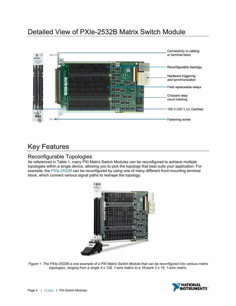
Detailed View of PXIe-2532B Matrix Switch Module
Key Features Reconfigurable Topologies As referenced in Table 1, many PXI Matrix Switch Modules can be reconfigured to achieve multiple topologies within a single device, allowing you to pick the topology that best suits your application. For example, the PXIe-2532B can be reconfigured by using one of many different front-mounting terminal block, which connect various signal paths to reshape the topology.
Figure 1. The PXIe-2532B is one example of a PXI Matrix Switch Module that can be reconfigured into various matrix
topologies, ranging from a single 4 x 128, 1-wire matrix to a 16-bank 2 x 16, 1-wire matrix.

Page 5 | ni.com | PXI Switch Modules
Synchronization and Integration NI switches use the inherent timing and synchronization capabilities of the PXI platform to communicate with other instruments within the PXI chassis1. You can store a list of switch connections in memory onboard the switch module and then use the integrated hardware scanning and triggering engine to advance the switch sequence and rapidly communicate with any PXI instrument that can send and receive digital triggers, such as DMM or oscilloscope. This advanced switching method removes the software overhead and reduces the bus latency associated with traditional software-controlled switching operations for faster test execution with more repeatable timing.
1Triggering is available on most NI switches. To check if this feature is supported by a switch module, reference the “Trigger Characteristics” section of the product specification document.

Page 6 | ni.com | PXI Switch Modules
Relay Health Monitoring To simplify relay maintenance and increase reliability in high-channel-count systems, NI PXI Matrix Switch Modules offer advanced relay health monitoring features, such as onboard relay count tracking, which is available on all NI switch modules, and functional and resistive self-tests, available through the NI Switch Health Center2.
Figure 2. The NI Switch Health center provides advanced relay health monitoring options, including functional and
resistive self-tests, onboard relay count tracking, and report generation.
2The NI Switch Health Center is available on some NI switches. To check if this feature is supported by a switch module, reference KnowledgeBase article: Which NI Switch Modules Support Resistive Self Test and Temperature Monitoring?
The NI Switch Health Center is a free application that installs with the NI-SWITCH driver that can be used to monitor individual relay health, guide relay replacement, and generate user reports. The NI Switch Health Center verifies the condition of each relay by sending a signal through a combination of routes and alerting users if a relay has failed stuck open or closed. Additionally, large changes in contact resistance over time can indicate that a relay is approaching, or has reached, end of life. The NI Switch Health Center tests for changes in resistance using the integrated relay resistance test, allowing you to view the resistance change across individual relays and determine whether a relay is nearing the end of its usable life. A large change in resistance from the baseline indicates that you will soon need to replace the relay. For more information on the Switch Health Center, relays, or switch topologies, see the NI Switch Health Center white paper.
Page 7 | ni.com | PXI Switch Modules
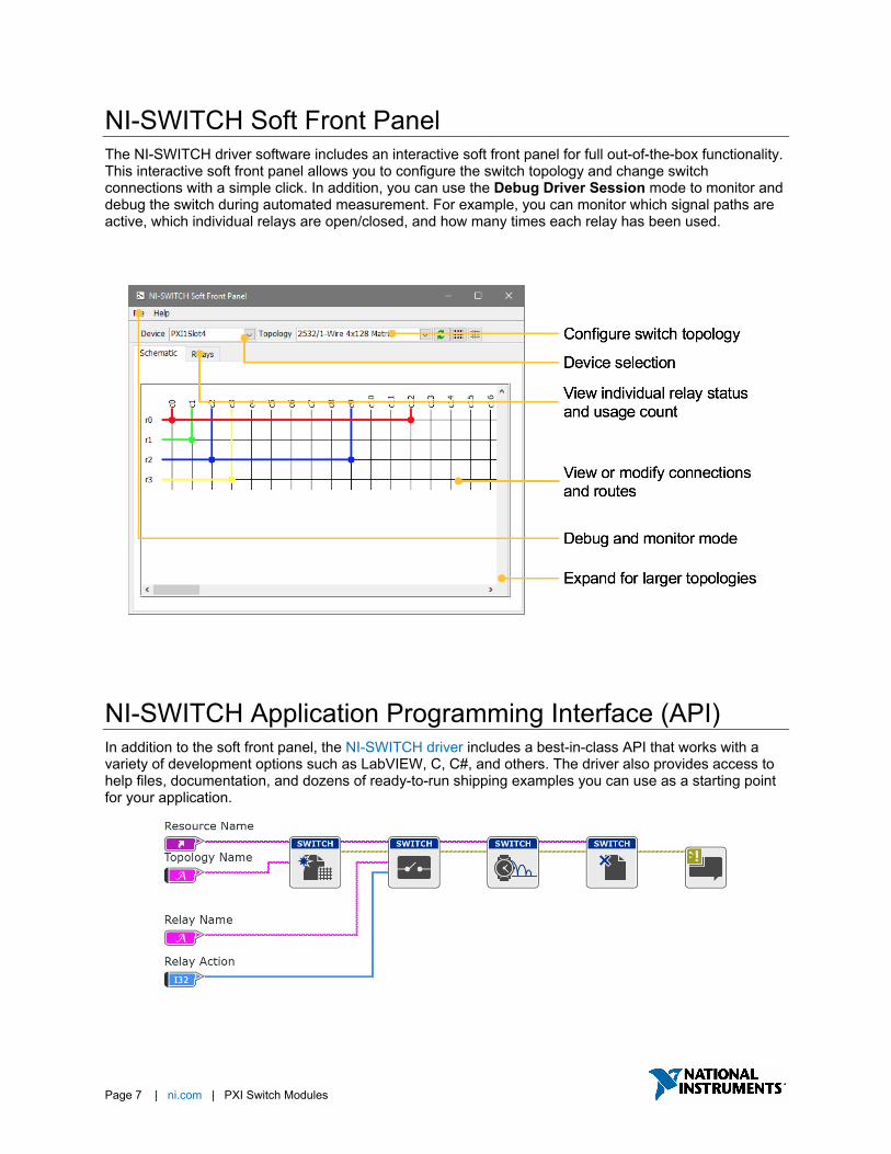
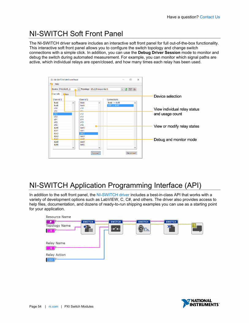
NI-SWITCH Soft Front Panel The NI-SWITCH driver software includes an interactive soft front panel for full out-of-the-box functionality. This interactive soft front panel allows you to configure the switch topology and change switch connections with a simple click. In addition, you can use the Debug Driver Session mode to monitor and debug the switch during automated measurement. For example, you can monitor which signal paths are active, which individual relays are open/closed, and how many times each relay has been used.
NI-SWITCH Application Programming Interface (API) In addition to the soft front panel, the NI-SWITCH driver includes a best-in-class API that works with a variety of development options such as LabVIEW, C, C#, and others. The driver also provides access to help files, documentation, and dozens of ready-to-run shipping examples you can use as a starting point for your application.

Have a question? Contact Us.
Page 8 | ni.com | PXI Switch Modules
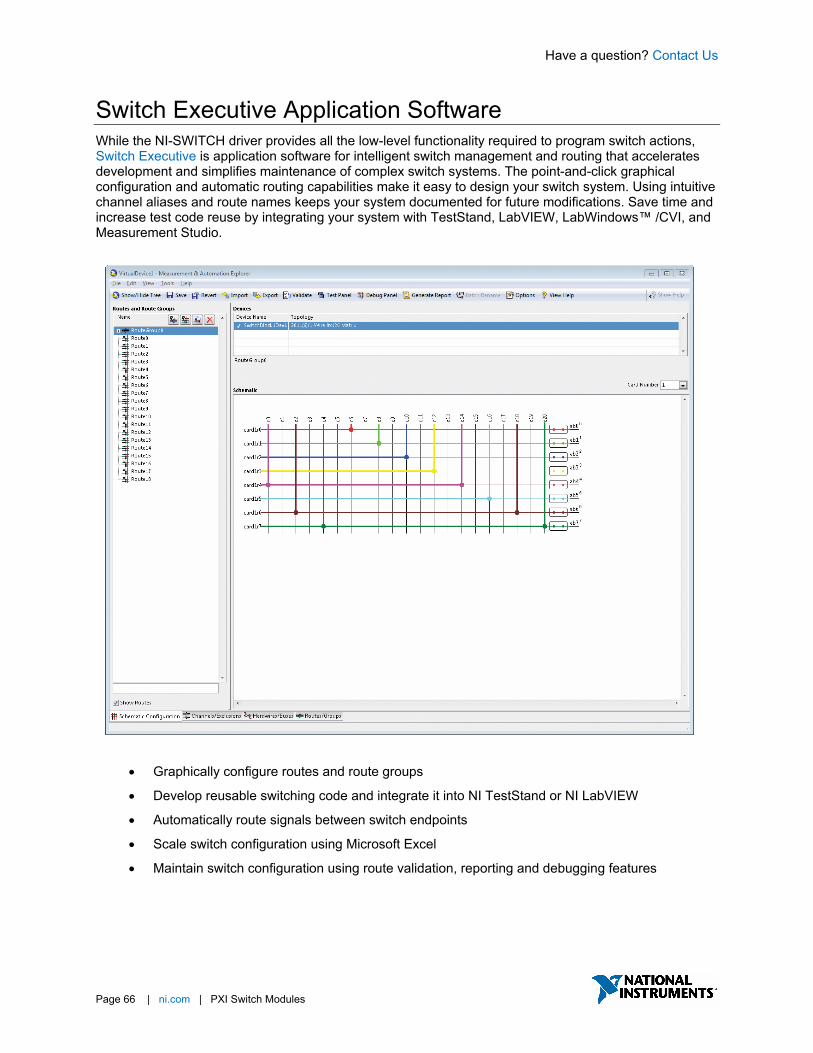
Switch Executive Application Software While the NI-SWITCH driver provides all the low-level functionality required to program switch actions, Switch Executive is application software for intelligent switch management and routing that accelerates development and simplifies maintenance of complex switch systems. The point-and-click graphical configuration and automatic routing capabilities make it easy to design your switch system. Using intuitive channel aliases and route names keeps your system documented for future modifications. Save time and increase test code reuse by integrating your system with TestStand, LabVIEW, LabWindows™ /CVI, and Measurement Studio.
• Graphically configure routes and route groups
• Develop reusable switching code and integrate it into NI TestStand or NI LabVIEW
• Automatically route signals between switch endpoints
• Scale switch configuration using Microsoft Excel
• Maintain switch configuration using route validation, reporting and debugging features
Have a question? Contact Us
Page 9 | ni.com | PXI Switch Modules
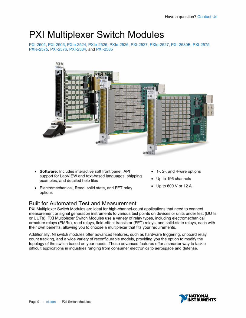
PXI Multiplexer Switch Modules PXI-2501, PXI-2503, PXIe-2524, PXIe-2525, PXIe-2526, PXI-2527, PXIe-2527, PXI-2530B, PXI-2575, PXIe-2575, PXI-2576, PXI-2584, and PXI-2585
• Software: Includes interactive soft front panel, API support for LabVIEW and text-based languages, shipping examples, and detailed help files
• Electromechanical, Reed, solid state, and FET relay options
• 1-, 2-, and 4-wire options
• Up to 196 channels
• Up to 600 V or 12 A
Built for Automated Test and Measurement PXI Multiplexer Switch Modules are ideal for high-channel-count applications that need to connect measurement or signal generation instruments to various test points on devices or units under test (DUTs or UUTs). PXI Multiplexer Switch Modules use a variety of relay types, including electromechanical armature relays (EMRs), reed relays, field-effect transistor (FET) relays, and solid-state relays, each with their own benefits, allowing you to choose a multiplexer that fits your requirements.
Additionally, NI switch modules offer advanced features, such as hardware triggering, onboard relay count tracking, and a wide variety of reconfigurable models, providing you the option to modify the topology of the switch based on your needs. These advanced features offer a smarter way to tackle difficult applications in industries ranging from consumer electronics to aerospace and defense.
Have a question? Contact Us
Page 10 | ni.com | PXI Switch Modules
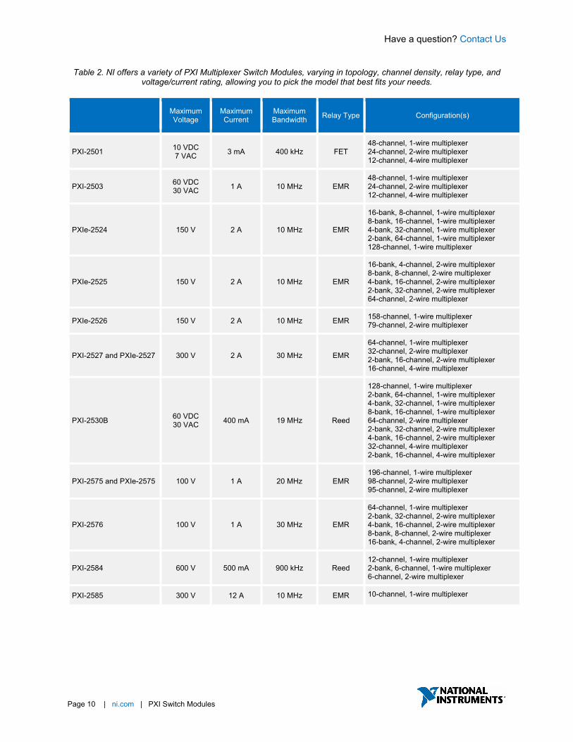
Table 2. NI offers a variety of PXI Multiplexer Switch Modules, varying in topology, channel density, relay type, and voltage/current rating, allowing you to pick the model that best fits your needs.
Maximum Voltage
Maximum Current
Maximum Bandwidth Relay Type Configuration(s)
PXI-2501 10 VDC 7 VAC 3 mA 400 kHz FET
48-channel, 1-wire multiplexer 24-channel, 2-wire multiplexer 12-channel, 4-wire multiplexer
PXI-2503 60 VDC 30 VAC 1 A 10 MHz EMR
48-channel, 1-wire multiplexer 24-channel, 2-wire multiplexer 12-channel, 4-wire multiplexer
PXIe-2524 150 V 2 A 10 MHz EMR
16-bank, 8-channel, 1-wire multiplexer 8-bank, 16-channel, 1-wire multiplexer 4-bank, 32-channel, 1-wire multiplexer 2-bank, 64-channel, 1-wire multiplexer 128-channel, 1-wire multiplexer
PXIe-2525 150 V 2 A 10 MHz EMR
16-bank, 4-channel, 2-wire multiplexer 8-bank, 8-channel, 2-wire multiplexer 4-bank, 16-channel, 2-wire multiplexer 2-bank, 32-channel, 2-wire multiplexer 64-channel, 2-wire multiplexer
PXIe-2526 150 V 2 A 10 MHz EMR 158-channel, 1-wire multiplexer 79-channel, 2-wire multiplexer
PXI-2527 and PXIe-2527 300 V 2 A 30 MHz EMR
64-channel, 1-wire multiplexer 32-channel, 2-wire multiplexer 2-bank, 16-channel, 2-wire multiplexer 16-channel, 4-wire multiplexer
PXI-2530B 60 VDC 30 VAC 400 mA 19 MHz Reed
128-channel, 1-wire multiplexer 2-bank, 64-channel, 1-wire multiplexer 4-bank, 32-channel, 1-wire multiplexer 8-bank, 16-channel, 1-wire multiplexer 64-channel, 2-wire multiplexer 2-bank, 32-channel, 2-wire multiplexer 4-bank, 16-channel, 2-wire multiplexer 32-channel, 4-wire multiplexer 2-bank, 16-channel, 4-wire multiplexer
PXI-2575 and PXIe-2575 100 V 1 A 20 MHz EMR 196-channel, 1-wire multiplexer 98-channel, 2-wire multiplexer 95-channel, 2-wire multiplexer
PXI-2576 100 V 1 A 30 MHz EMR
64-channel, 1-wire multiplexer 2-bank, 32-channel, 2-wire multiplexer 4-bank, 16-channel, 2-wire multiplexer 8-bank, 8-channel, 2-wire multiplexer 16-bank, 4-channel, 2-wire multiplexer
PXI-2584 600 V 500 mA 900 kHz Reed 12-channel, 1-wire multiplexer 2-bank, 6-channel, 1-wire multiplexer 6-channel, 2-wire multiplexer
PXI-2585 300 V 12 A 10 MHz EMR 10-channel, 1-wire multiplexer

Have a question? Contact Us
Page 11 | ni.com | PXI Switch Modules
Detailed View of PXIe-2527 Multiplexer Switch Module
Key Features Reconfigurable Topologies As referenced in Table 1, many PXI Multiplexer Switch Modules can be reconfigured to achieve multiple topologies within a single device, allowing you to pick the topology that best suits your application. In some cases, such as the PXIe-2524, this operation can be done in software, without any additional hardware, by using internal relays to reshape the topology. In other cases, such as the PXI-2530B, it requires different terminal blocks, which connect various signal paths to reshape the topology.
Figure 3. The PXIe-2524 is one example of a PXI Multiplexer Switch Module that can be reconfigured into various multiplexer topologies, ranging from 16 independent 8-channel multiplexers to a single 128-channel multiplexer.

Have a question? Contact Us
Page 12 | ni.com | PXI Switch Modules
Synchronization and Integration NI switches use the inherent timing and synchronization capabilities of the PXI platform to communicate with other instruments within the PXI chassis1. You can store a list of switch connections in memory onboard the switch module and then use the integrated hardware scanning and triggering engine to advance the switch sequence and rapidly communicate with any PXI instrument that can send and receive digital triggers, such as DMM or oscilloscope. This advanced switching method removes the software overhead and reduces the bus latency associated with traditional software-controlled switching operations for faster test execution with more repeatable timing.
1Triggering is available on most NI switches. To check if this feature is supported by a switch module, reference the “Trigger Characteristics” section of the product specification document.

Have a question? Contact Us
Page 13 | ni.com | PXI Switch Modules
NI-SWITCH Soft Front Panel The NI-SWITCH driver software includes an interactive soft front panel for full out-of-the-box functionality. This interactive soft front panel allows you to configure the switch topology and change switch connections with a simple click. In addition, you can use the Debug Driver Session mode to monitor and debug the switch during automated measurement. For example, you can monitor which signal paths are active, which individual relays are open/closed, and how many times each relay has been used.
NI-SWITCH Application Programming Interface (API) In addition to the soft front panel, the NI-SWITCH driver includes a best-in-class API that works with a variety of development options such as LabVIEW, C, C#, and others. The driver also provides access to help files, documentation, and dozens of ready-to-run shipping examples you can use as a starting point for your application.

Have a question? Contact Us.
Page 14 | ni.com | PXI Switch Modules
Switch Executive Application Software While the NI-SWITCH driver provides all the low-level functionality required to program switch actions, Switch Executive is application software for intelligent switch management and routing that accelerates development and simplifies maintenance of complex switch systems. The point-and-click graphical configuration and automatic routing capabilities make it easy to design your switch system. Using intuitive channel aliases and route names keeps your system documented for future modifications. Save time and increase test code reuse by integrating your system with TestStand, LabVIEW, LabWindows™ /CVI, and Measurement Studio.
• Graphically configure routes and route groups
• Develop reusable switching code and integrate it into NI TestStand or NI LabVIEW
• Automatically route signals between switch endpoints
• Scale switch configuration using Microsoft Excel
• Maintain switch configuration using route validation, reporting and debugging features

Have a question? Contact Us
Page 15 | ni.com | PXI Switch Modules
PXI Relay Modules PXI-2520, PXI-2521, PXI-2522, PXI-2523, PXI-2564, PXI-2565, PXI-2566, PXI-2568, PXI-2569, PXIe-2569, PXI-2570, PXI-2571, and PXI-2586
• Software: Includes interactive soft front panel, API support for LabVIEW and text-based languages, shipping examples, and detailed help files
• SPST, SPDT, DPST, and DPDT options
• Up to 100 relays
• Up to 300 V or 12 A
Built for Automated Test and Measurement PXI Relay Modules consist of multiple, independent, electromechanical armature relays and come in a variety of configurations, such as single-pole single-throw (SPST), single-pole double-throw (SPDT), and double-pole double-throw (DPDT) relays. PXI Relay Modules are ideal for high-channel-count applications that need to connect measurement or signal generation instruments to various test points on devices or units under test (DUTs or UUTs).
Additionally, NI switch modules offer advanced features, such as hardware triggering, onboard relay count tracking, and a wide variety of reconfigurable models, providing you the option to modify the topology of the switch based on your needs. These advanced features offer a smarter way to tackle difficult applications in industries ranging from consumer electronics to aerospace and defense.
Have a question? Contact Us
Page 16 | ni.com | PXI Switch Modules
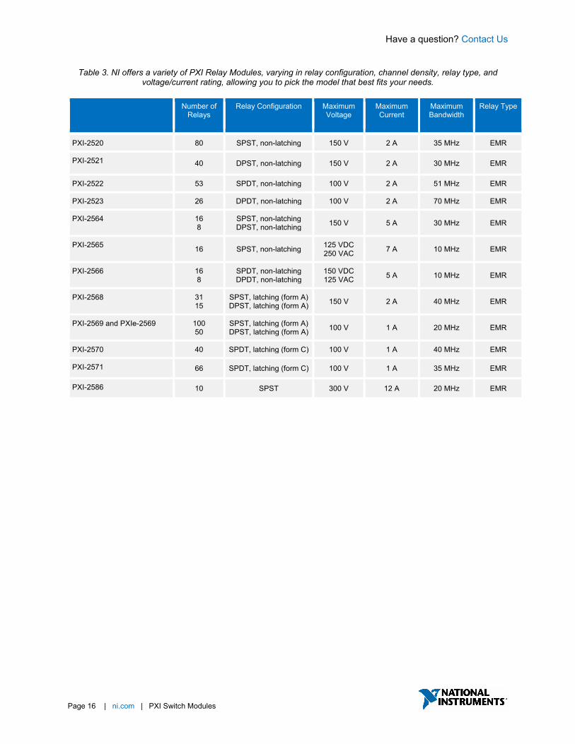
Table 3. NI offers a variety of PXI Relay Modules, varying in relay configuration, channel density, relay type, and voltage/current rating, allowing you to pick the model that best fits your needs.
Number of Relays
Relay Configuration Maximum Voltage
Maximum Current
Maximum Bandwidth
Relay Type
PXI-2520 80 SPST, non-latching 150 V 2 A 35 MHz EMR
PXI-2521 40 DPST, non-latching 150 V 2 A 30 MHz EMR
PXI-2522 53 SPDT, non-latching 100 V 2 A 51 MHz EMR
PXI-2523 26 DPDT, non-latching 100 V 2 A 70 MHz EMR
PXI-2564 16 8
SPST, non-latching DPST, non-latching 150 V 5 A 30 MHz EMR
PXI-2565 16 SPST, non-latching 125 VDC 250 VAC 7 A 10 MHz EMR
PXI-2566 16 8
SPDT, non-latching DPDT, non-latching
150 VDC 125 VAC 5 A 10 MHz EMR
PXI-2568 31 15
SPST, latching (form A) DPST, latching (form A) 150 V 2 A 40 MHz EMR
PXI-2569 and PXIe-2569 100 50
SPST, latching (form A) DPST, latching (form A) 100 V 1 A 20 MHz EMR
PXI-2570 40 SPDT, latching (form C) 100 V 1 A 40 MHz EMR
PXI-2571 66 SPDT, latching (form C) 100 V 1 A 35 MHz EMR
PXI-2586 10 SPST 300 V 12 A 20 MHz EMR

Have a question? Contact Us
Page 17 | ni.com | PXI Switch Modules
Detailed View of PXIe-2569 Relay Module
Key Features Reconfigurable Topologies As referenced in Table 1, some PXI Relay Modules can be reconfigured to achieve multiple topologies within a single device, allowing you to pick the topology that best suits your application. For example, the PXIe-2569 can be reconfigured in software, without any additional hardware, allowing you to reshape the topology into either 100 SPST relays or 50 DPST relays.
Figure 4. The PXI/PXIe-2569 is one example of a PXI Relay Module that can be reconfigured into either 100 SPST
relays or 50 DPST relays.

Have a question? Contact Us
Page 18 | ni.com | PXI Switch Modules
Synchronization and Integration NI switches use the inherent timing and synchronization capabilities of the PXI platform to communicate with other instruments within the PXI chassis1. You can store a list of switch connections in memory onboard the switch module and then use the integrated hardware scanning and triggering engine to advance the switch sequence and rapidly communicate with any PXI instrument that can send and receive digital triggers, such as DMM or oscilloscope. This advanced switching method removes the software overhead and reduces the bus latency associated with traditional software-controlled switching operations for faster test execution with more repeatable timing.
1Triggering is available on most NI switches. To check if this feature is supported by a switch module, reference the “Trigger Characteristics” section of the product specification document.

Have a question? Contact Us
Page 19 | ni.com | PXI Switch Modules
NI-SWITCH Soft Front Panel The NI-SWITCH driver software includes an interactive soft front panel for full out-of-the-box functionality. This interactive soft front panel allows you to configure the switch topology and change switch connections with a simple click. In addition, you can use the Debug Driver Session mode to monitor and debug the switch during automated measurement. For example, you can monitor which signal paths are active, which individual relays are open/closed, and how many times each relay has been used.
NI-SWITCH Application Programming Interface (API) In addition to the soft front panel, the NI-SWITCH driver includes a best-in-class API that works with a variety of development options such as LabVIEW, C, C#, and others. The driver also provides access to help files, documentation, and dozens of ready-to-run shipping examples you can use as a starting point for your application.

Have a question? Contact Us.
Page 20 | ni.com | PXI Switch Modules
Switch Executive Application Software While the NI-SWITCH driver provides all the low-level functionality required to program switch actions, Switch Executive is application software for intelligent switch management and routing that accelerates development and simplifies maintenance of complex switch systems. The point-and-click graphical configuration and automatic routing capabilities make it easy to design your switch system. Using intuitive channel aliases and route names keeps your system documented for future modifications. Save time and increase test code reuse by integrating your system with TestStand, LabVIEW, LabWindows™ /CVI, and Measurement Studio.
• Graphically configure routes and route groups
• Develop reusable switching code and integrate it into NI TestStand or NI LabVIEW
• Automatically route signals between switch endpoints
• Scale switch configuration using Microsoft Excel
• Maintain switch configuration using route validation, reporting and debugging features
Have a question? Contact Us
Page 21 | ni.com | PXI Switch Modules
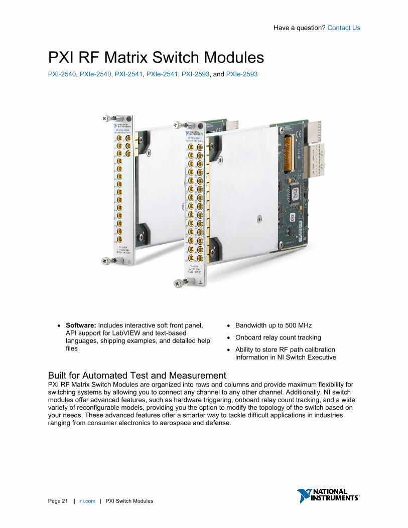
PXI RF Matrix Switch Modules PXI-2540, PXIe-2540, PXI-2541, PXIe-2541, PXI-2593, and PXIe-2593
• Software: Includes interactive soft front panel, API support for LabVIEW and text-based languages, shipping examples, and detailed help files
• Bandwidth up to 500 MHz
• Onboard relay count tracking
• Ability to store RF path calibration information in NI Switch Executive
Built for Automated Test and Measurement PXI RF Matrix Switch Modules are organized into rows and columns and provide maximum flexibility for switching systems by allowing you to connect any channel to any other channel. Additionally, NI switch modules offer advanced features, such as hardware triggering, onboard relay count tracking, and a wide variety of reconfigurable models, providing you the option to modify the topology of the switch based on your needs. These advanced features offer a smarter way to tackle difficult applications in industries ranging from consumer electronics to aerospace and defense.
Have a question? Contact Us
Page 22 | ni.com | PXI Switch Modules
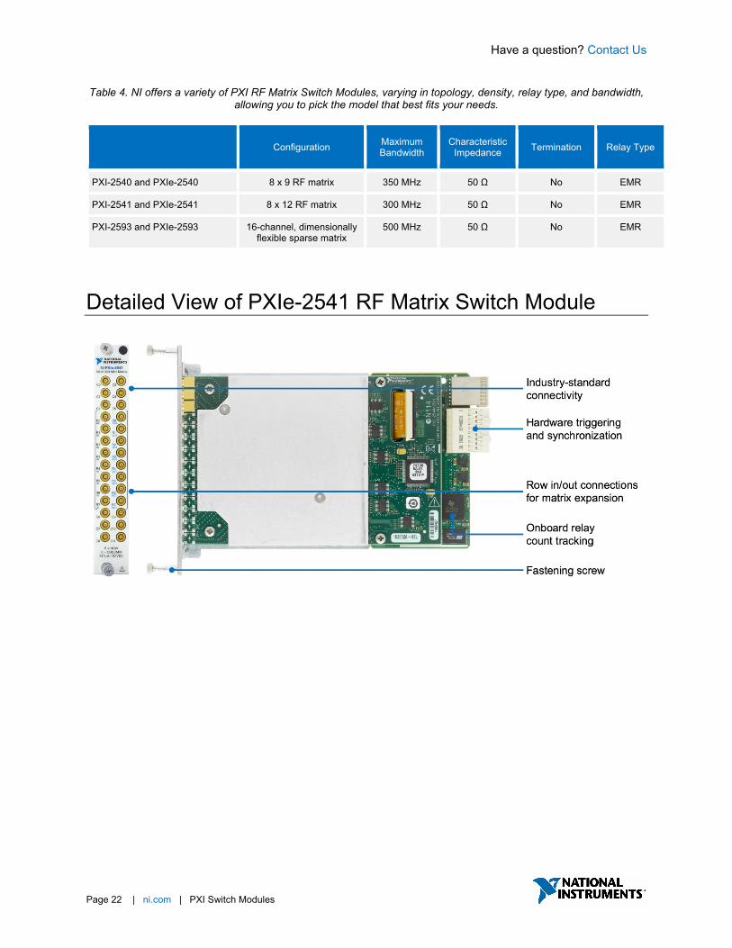
Table 4. NI offers a variety of PXI RF Matrix Switch Modules, varying in topology, density, relay type, and bandwidth, allowing you to pick the model that best fits your needs.
Configuration Maximum
Bandwidth Characteristic
Impedance Termination Relay Type
PXI-2540 and PXIe-2540 8 x 9 RF matrix 350 MHz 50 Ω No EMR
PXI-2541 and PXIe-2541 8 x 12 RF matrix 300 MHz 50 Ω No EMR
PXI-2593 and PXIe-2593 16-channel, dimensionally flexible sparse matrix
500 MHz 50 Ω No EMR
Detailed View of PXIe-2541 RF Matrix Switch Module
Have a question? Contact Us
Page 23 | ni.com | PXI Switch Modules
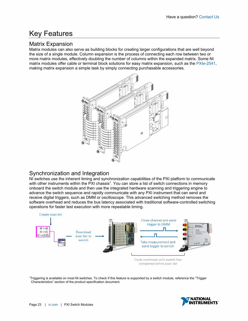
Key Features Matrix Expansion Matrix modules can also serve as building blocks for creating larger configurations that are well beyond the size of a single module. Column expansion is the process of connecting each row between two or more matrix modules, effectively doubling the number of columns within the expanded matrix. Some NI matrix modules offer cable or terminal block solutions for easy matrix expansion, such as the PXIe-2541, making matrix expansion a simple task by simply connecting purchasable accessories.
Synchronization and Integration NI switches use the inherent timing and synchronization capabilities of the PXI platform to communicate with other instruments within the PXI chassis1. You can store a list of switch connections in memory onboard the switch module and then use the integrated hardware scanning and triggering engine to advance the switch sequence and rapidly communicate with any PXI instrument that can send and receive digital triggers, such as DMM or oscilloscope. This advanced switching method removes the software overhead and reduces the bus latency associated with traditional software-controlled switching operations for faster test execution with more repeatable timing.
1Triggering is available on most NI switches. To check if this feature is supported by a switch module, reference the “Trigger Characteristics” section of the product specification document.

Have a question? Contact Us
Page 24 | ni.com | PXI Switch Modules
NI-SWITCH Soft Front Panel The NI-SWITCH driver software includes an interactive soft front panel for full out-of-the-box functionality. This interactive soft front panel allows you to configure the switch topology and change switch connections with a simple click. In addition, you can use the Debug Driver Session mode to monitor and debug the switch during automated measurement. For example, you can monitor which signal paths are active, which individual relays are open/closed, and how many times each relay has been used.
NI-SWITCH Application Programming Interface (API) In addition to the soft front panel, the NI-SWITCH driver includes a best-in-class API that works with a variety of development options such as LabVIEW, C, C#, and others. The driver also provides access to help files, documentation, and dozens of ready-to-run shipping examples you can use as a starting point for your application.

Have a question? Contact Us.
Page 25 | ni.com | PXI Switch Modules
Switch Executive Application Software While the NI-SWITCH driver provides all the low-level functionality required to program switch actions, Switch Executive is application software for intelligent switch management and routing that accelerates development and simplifies maintenance of complex switch systems. The point-and-click graphical configuration and automatic routing capabilities make it easy to design your switch system. Using intuitive channel aliases and route names keeps your system documented for future modifications. Save time and increase test code reuse by integrating your system with TestStand, LabVIEW, LabWindows™ /CVI, and Measurement Studio.
• Graphically configure routes and route groups
• Develop reusable switching code and integrate it into NI TestStand or NI LabVIEW
• Automatically route signals between switch endpoints
• Scale switch configuration using Microsoft Excel
• Maintain switch configuration using route validation, reporting and debugging features

Have a question? Contact Us
Page 26 | ni.com | PXI Switch Modules
PXI RF Multiplexer Switch Modules PXI-2543, PXIe-2543, PXI-2544, PXIe-2544, PXI-2545, PXI-2546, PXI-2547, PXI-2554, PXI-2555, PXI-2556, PXI-2557, PXI-2593, PXIe-2593, PXI-2594, PXI-2595, PXI-2596, PXI-2597, PXIe-2746, PXIe-2747, PXIe-2748, PXI-2796, and PXI-2797
• Software: Includes interactive soft front panel, API support for LabVIEW and text-based languages, shipping examples, and detailed help files
• Electromechanical and FET relay options
• Bandwidth up to 40 GHz
• Unterminated and terminated options
• Onboard relay count tracking
• Ability to store RF path calibration information in NI Switch Executive
Built for Automated Test and Measurement PXI RF Multiplexer Switch Modules are ideal for high-channel-count applications that need to connect measurement or signal generation instruments to various test points on devices or units under test (DUTs or UUTs). PXI RF Multiplexer Switch Modules use a variety of relay types, including electromechanical armature relays, reed relays, field-effect transistor (FET) relays, and solid-state relays, each with their own benefits, allowing you to choose a multiplexer that fits your requirements.
Additionally, NI switch modules offer advanced features, such as hardware triggering, onboard relay count tracking, and a wide variety of reconfigurable models, providing you the option to modify the topology of the switch based on your needs. These advanced features offer a smarter way to tackle difficult applications in industries ranging from consumer electronics to aerospace and defense.
Have a question? Contact Us
Page 27 | ni.com | PXI Switch Modules
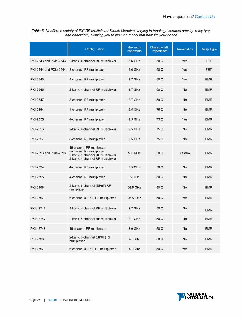
Table 5. NI offers a variety of PXI RF Multiplexer Switch Modules, varying in topology, channel density, relay type, and bandwidth, allowing you to pick the model that best fits your needs.
Configuration Maximum
Bandwidth Characteristic
Impedance Termination Relay Type
PXI-2543 and PXIe-2543 2-bank, 4-channel RF multiplexer 6.6 GHz 50 Ω Yes FET
PXI-2544 and PXIe-2544 8-channel RF multiplexer 6.6 GHz 50 Ω Yes FET
PXI-2545 4-channel RF multiplexer 2.7 GHz 50 Ω Yes EMR
PXI-2546 2-bank, 4-channel RF multiplexer 2.7 GHz 50 Ω No EMR
PXI-2547 8-channel RF multiplexer 2.7 GHz 50 Ω No EMR
PXI-2554 4-channel RF multiplexer 2.5 GHz 75 Ω No EMR
PXI-2555 4-channel RF multiplexer 2.5 GHz 75 Ω Yes EMR
PXI-2556 2-bank, 4-channel RF multiplexer 2.5 GHz 75 Ω No EMR
PXI-2557 8-channel RF multiplexer 2.5 GHz 75 Ω No EMR
PXI-2593 and PXIe-2593
16-channel RF multiplexer 8-channel RF multiplexer 2-bank, 8-channel RF multiplexer 2-bank, 4-channel RF multiplexer
500 MHz 50 Ω Yes/No EMR
PXI-2594 4-channel RF multiplexer 2.5 GHz 50 Ω No EMR
PXI-2595 4-channel RF multiplexer 5 GHz 50 Ω No EMR
PXI-2596 2-bank, 6-channel (SP6T) RF multiplexer 26.5 GHz 50 Ω No EMR
PXI-2597 6-channel (SP6T) RF multiplexer 26.5 GHz 50 Ω Yes EMR
PXIe-2746 4-bank, 4-channel RF multiplexer 2.7 GHz 50 Ω No EMR
PXIe-2747 2-bank, 8-channel RF multiplexer 2.7 GHz 50 Ω No EMR
PXIe-2748 16-channel RF multiplexer 3.0 GHz 50 Ω No EMR
PXI-2796 2-bank, 6-channel (SP6T) RF multiplexer 40 GHz 50 Ω No EMR
PXI-2797 6-channel (SP6T) RF multiplexer 40 GHz 50 Ω Yes EMR
Have a question? Contact Us
Page 28 | ni.com | PXI Switch Modules
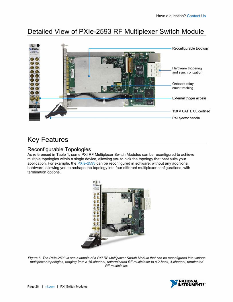
Detailed View of PXIe-2593 RF Multiplexer Switch Module
Key Features Reconfigurable Topologies As referenced in Table 1, some PXI RF Multiplexer Switch Modules can be reconfigured to achieve multiple topologies within a single device, allowing you to pick the topology that best suits your application. For example, the PXIe-2593 can be reconfigured in software, without any additional hardware, allowing you to reshape the topology into four different multiplexer configurations, with termination options.
Figure 5. The PXIe-2593 is one example of a PXI RF Multiplexer Switch Module that can be reconfigured into various
multiplexer topologies, ranging from a 16-channel, unterminated RF multiplexer to a 2-bank, 4-channel, terminated RF multiplexer.

Have a question? Contact Us
Page 29 | ni.com | PXI Switch Modules
Synchronization and Integration NI switches use the inherent timing and synchronization capabilities of the PXI platform to communicate with other instruments within the PXI chassis1. You can store a list of switch connections in memory onboard the switch module and then use the integrated hardware scanning and triggering engine to advance the switch sequence and rapidly communicate with any PXI instrument that can send and receive digital triggers, such as DMM or oscilloscope. This advanced switching method removes the software overhead and reduces the bus latency associated with traditional software-controlled switching operations for faster test execution with more repeatable timing.
1Triggering is available on most NI switches. To check if this feature is supported by a switch module, reference the “Trigger Characteristics” section of the product specification document.

Have a question? Contact Us
Page 30 | ni.com | PXI Switch Modules
NI-SWITCH Soft Front Panel The NI-SWITCH driver software includes an interactive soft front panel for full out-of-the-box functionality. This interactive soft front panel allows you to configure the switch topology and change switch connections with a simple click. In addition, you can use the Debug Driver Session mode to monitor and debug the switch during automated measurement. For example, you can monitor which signal paths are active, which individual relays are open/closed, and how many times each relay has been used.
NI-SWITCH Application Programming Interface (API) In addition to the soft front panel, the NI-SWITCH driver includes a best-in-class API that works with a variety of development options such as LabVIEW, C, C#, and others. The driver also provides access to help files, documentation, and dozens of ready-to-run shipping examples you can use as a starting point for your application.

Have a question? Contact Us.
Page 31 | ni.com | PXI Switch Modules
Switch Executive Application Software While the NI-SWITCH driver provides all the low-level functionality required to program switch actions, Switch Executive is application software for intelligent switch management and routing that accelerates development and simplifies maintenance of complex switch systems. The point-and-click graphical configuration and automatic routing capabilities make it easy to design your switch system. Using intuitive channel aliases and route names keeps your system documented for future modifications. Save time and increase test code reuse by integrating your system with TestStand, LabVIEW, LabWindows™ /CVI, and Measurement Studio.
• Graphically configure routes and route groups
• Develop reusable switching code and integrate it into NI TestStand or NI LabVIEW
• Automatically route signals between switch endpoints
• Scale switch configuration using Microsoft Excel
• Maintain switch configuration using route validation, reporting and debugging features
Have a question? Contact Us
Page 32 | ni.com | PXI Switch Modules
PXI RF Relay Modules PXI-2542, PXIe-2542, PXI-2548, PXI-2549, PXI-2558, PXI-2559, PXI-2599, and PXI-2799
• Software: Includes interactive soft front panel, API support for LabVIEW and text-based languages, shipping examples, and detailed help files
• Electromechanical and FET relay options
• Bandwidth up to 40 GHz
• Unterminated and terminated options
• Onboard relay count tracking
• Ability to store RF path calibration information in NI Switch Executive
Built for Automated Test and Measurement PXI RF Relay Modules offer single-pole double-throw (SPDT) and terminated switches. SPDT models include excellent insertion loss, voltage standing-wave ratio (VSWR), and isolation parameters to minimize signal degradation. You can use the onboard relay-count-tracking feature on these models to predict relay lifetime and reduce unexpected system downtime. SPDT models are also well-suited for passing high-order harmonics from PXI RF Signal Upconverter Modules or routing multiple sources to PXI RF Signal Downconverter Modules. Terminated switch models feature front-mounted SMA connectors and high-performance solid-state relays for fast switching time and unlimited mechanical lifetime. These models also include termination on every COM line and channel, which helps minimize reflections of the RF signal and protect your instruments.
Additionally, NI switch modules offer advanced features, such as hardware triggering, onboard relay count tracking, and a wide variety of reconfigurable models, providing you the option to modify the topology of the switch based on your needs. These advanced features offer a smarter way to tackle difficult applications in industries ranging from consumer electronics to aerospace and defense.

Have a question? Contact Us
Page 33 | ni.com | PXI Switch Modules
Table 6. NI offers a variety of PXI RF Relay Modules, varying in relay configuration, channel density, relay type, and bandwidth, allowing you to pick the model that best fits your needs.
Number of Relays Relay Configuration Maximum
Bandwidth Characteristic
Impedance Termination Relay Type
PXI-2542 and PXIe-2542 4 SPDT 6.6 GHz 50 Ω Yes FET
PXI-2548 4 SPDT, latching 2.7 GHz 50 Ω No EMR
PXI-2549 2 SPDT, latching 2.7 GHz 50 Ω Yes EMR
PXI-2558 4 SPDT, latching 2.5 GHz 75 Ω No EMR
PXI-2559 2 SPDT, latching 2.5 GHz 75 Ω Yes EMR
PXI-2599 2 SPDT, latching 26.5 GHz 50 Ω No EMR
PXI-2799 2 SPDT, latching 40 GHz 50 Ω No EMR
Detailed View of PXIe-2542 RF Relay Module

Have a question? Contact Us
Page 34 | ni.com | PXI Switch Modules
Key Features Synchronization and Integration NI switches use the inherent timing and synchronization capabilities of the PXI platform to communicate with other instruments within the PXI chassis1. You can store a list of switch connections in memory onboard the switch module and then use the integrated hardware scanning and triggering engine to advance the switch sequence and rapidly communicate with any PXI instrument that can send and receive digital triggers, such as DMM or oscilloscope. This advanced switching method removes the software overhead and reduces the bus latency associated with traditional software-controlled switching operations for faster test execution with more repeatable timing.
1Triggering is available on most NI switches. To check if this feature is supported by a switch module, reference the “Trigger Characteristics” section of the product specification document.

Have a question? Contact Us
Page 35 | ni.com | PXI Switch Modules
NI-SWITCH Soft Front Panel The NI-SWITCH driver software includes an interactive soft front panel for full out-of-the-box functionality. This interactive soft front panel allows you to configure the switch topology and change switch connections with a simple click. In addition, you can use the Debug Driver Session mode to monitor and debug the switch during automated measurement. For example, you can monitor which signal paths are active, which individual relays are open/closed, and how many times each relay has been used.
NI-SWITCH Application Programming Interface (API) In addition to the soft front panel, the NI-SWITCH driver includes a best-in-class API that works with a variety of development options such as LabVIEW, C, C#, and others. The driver also provides access to help files, documentation, and dozens of ready-to-run shipping examples you can use as a starting point for your application.

Have a question? Contact Us.
Page 36 | ni.com | PXI Switch Modules
Switch Executive Application Software While the NI-SWITCH driver provides all the low-level functionality required to program switch actions, Switch Executive is application software for intelligent switch management and routing that accelerates development and simplifies maintenance of complex switch systems. The point-and-click graphical configuration and automatic routing capabilities make it easy to design your switch system. Using intuitive channel aliases and route names keeps your system documented for future modifications. Save time and increase test code reuse by integrating your system with TestStand, LabVIEW, LabWindows™ /CVI, and Measurement Studio.
• Graphically configure routes and route groups
• Develop reusable switching code and integrate it into NI TestStand or NI LabVIEW
• Automatically route signals between switch endpoints
• Scale switch configuration using Microsoft Excel
• Maintain switch configuration using route validation, reporting and debugging features

Have a question? Contact Us
Page 37 | ni.com | PXI Switch Modules
SwitchBlock PXI Carrier Module for SwitchBlock and Matrix Modules for SwitchBlock PXI-2800, SWB-2810, SWB-2811, SWB-2812, SWB-2813, SWB-2814, SWB-2815, SWB-2816, SWB-2817, SWB-2833, and SWB-2834
• Software: Includes interactive soft front panel, API support for LabVIEW and text-based languages, shipping examples, and detailed help files
• Electromechanical and Reed relay options
• Relay health monitoring through the NI Switch Health Center
• Up to 2,000 crosspoints in a single carrier
• Up to 8,000 crosspoints in a single 18-slot PXI chassis
• 1- and 2-wire options
• Up to 150 V or 2 A
Built for Automated Test and Measurement SwitchBlock is a flexible and intelligent solution for creating large matrix switches that minimizes wiring and simplifies connectivity. The PXI Carrier Module for SwitchBlock occupies four PXI slots, holds up to six Matrix Modules for SwitchBlock, and includes an integrated analog bus for combining individual matrices into a single, large matrix. By connecting multiple SwitchBlock relay cards through the carrier’s integrated analog bus, you can easily create large matrices with more than 2,000 crosspoints in four PXI slots and more than 8,000 crosspoints in a single PXI chassis.
Additionally, NI SwitchBlock systems offer advanced features, such as relay health monitoring and onboard relay count tracking, providing you with an intelligent way to monitor the health of your switching system. These advanced features offer a smarter way to tackle difficult applications in industries ranging from consumer electronics to aerospace and defense.

Have a question? Contact Us
Page 38 | ni.com | PXI Switch Modules
Table 7. NI offers a variety of Matrix Modules for SwitchBlock, varying in topology, density, relay type, and voltage/current rating, allowing you to pick the model that best fits your needs. Each PXI Carrier Module for
SwitchBlock can hold up to six Matrix Modules for SwitchBlock.
Maximum Voltage
Maximum Current
Maximum Bandwidth
Relay Type
Number of Slots (Within a SwitchBlock
Carrier Module) Configuration(s)
SWB-2810 150 V 1 A 10 MHz Reed 1 4 x 43, 1-wire matrix
SWB-2811 150 V 1 A 15 MHz Reed 1 8 x 21, 1-wire matrix
SWB-2812 150 V 1 A 10 MHz Reed 1 16 x 9, 1-wire matrix
SWB-2813 150 V 1 A 8 MHz Reed 1 4 x 21, 2-wire matrix
SWB-2814 150 V 1 A 10 MHz Reed 1 8 x 9, 2-wire matrix
SWB-2815 100 V 300 mA 6 MHz Reed 1 4 x 86, 1-wire matrix
SWB-2816 100 V 300 mA 8 MHz Reed 1 8 x 46, 1-wire matrix
SWB-2817 100 V 300 mA 5 MHz Reed 1 16 x 22, 1-wire matrix
SWB-2833 100 V 2 A 10 MHz EMR 2 4 x 71, 2-wire matrix
SWB-2834 100 V 2 A 10 MHz EMR 2 8 x 34, 2-wire matrix
Note: Matrix Modules for SwitchBlock cannot be used in a PXI chassis without a PXI Carrier Module for SwitchBlock, which serves
as a sub-chassis within a PXI system. Each PXI Carrier Module for SwitchBlock can hold up to six Matrix Modules for SwitchBlock.
Have a question? Contact Us
Page 39 | ni.com | PXI Switch Modules
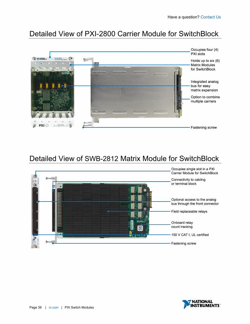
Detailed View of PXI-2800 Carrier Module for SwitchBlock
Detailed View of SWB-2812 Matrix Module for SwitchBlock

Have a question? Contact Us
Page 40 | ni.com | PXI Switch Modules
Key Features Relay Health Monitoring To simplify relay maintenance and increase reliability in high-channel-count systems, NI Matrix Switch Modules for SwitchBlock offer advanced relay health monitoring features, such as onboard relay count tracking, which is available on all NI switch modules, and functional relay self-tests, available through the NI Switch Health Center2.
Figure 6. The NI Switch Health center provides advanced relay health monitoring options, including functional and
resistive self-tests, onboard relay count tracking, and report generation.
2The NI Switch Health Center is available all Matrix Modules for SwitchBlock, but the resistive relay self-test feature is only available on some PXI Matrix Switch Modules. To find out which devices support the resistive relay self-test feature, reference KnowledgeBase article: Which NI Switch Modules Support Resistive Self Test and Temperature Monitoring?
The NI Switch Health Center is a free application that installs with the NI-SWITCH driver that can be used to monitor individual relay health, guide relay replacement, and generate user reports. The NI Switch Health Center verifies the condition of each relay by sending a signal through a combination of routes and alerting users if a relay has failed stuck open or closed.
For more information on the Switch Health Center, relays, or switch topologies, see the NI Switch Health Center white paper.
Designed for Matrix Expansion The customizable hardware design of the NI SwitchBlock makes it easy to create large switch matrices in PXI while minimizing wiring, simplifying connectivity, and providing a high degree of flexibility for your switching needs. A SwitchBlock system comprises a PXI Carrier Module for SwitchBlock (PXI-2800) that occupies four PXI slots and can hold up to six 1-slot or 3 2-slot Matrix Modules for SwitchBlock. The PXI Carrier Module for SwitchBlock features a hybrid-compatible connector, on the back of the second PXI slot, which allows you to place it in a PXI chassis or in a hybrid-compatible slot of a PXI Express chassis.

Have a question? Contact Us
Page 41 | ni.com | PXI Switch Modules
Figure 7. The PXI Carrier Module for SwitchBlock (PXI-2800) occupies four PXI slots, can hold up to six 1-slot Matrix Modules for SwitchBlock, and has an integrated analog bus designed to combine those matrix modules into a single
large matrix, without additional external wiring.
The PXI Carrier Module for SwitchBlock (PXI-2800) has an integrated analog bus, allowing for easy matrix expansion without the need for additional external cabling. Each Matrix Module for SwitchBlock has analog bus relays that connect its rows to the analog buss of the carrier, effectively combining any matrices that are connected to the analog bus.
Figure 8. SwitchBlock is designed for easy matrix expansion, allowing up to 2,000 crosspoints in a single PXI Carrier
Module for SwitchBlock (PXI-2800). Simply close the analog bus relays to connect that Matrix Module for SwitchBlock with any other devices connected to the analog bus.
Each Matrix Module for SwitchBlock is available in Type A and Type B configurations. The connector on the Type A card provides user access to the columns of the relay card as well as indirect row access, through the analog bus of the carrier. To preserve system bandwidth, Type B cards do not connect the analog bus to the front connector and only provide access to the columns through the front connector. Type A cards allow access to the rows of the matrix indirectly through the analog bus, via the analog bus connector pins. To optimize bandwidth, only one Type A card can connect to the analog bus at a single time, so most large SwitchBlock matrix systems have a single Type A card and the rest are Type B cards of the same model number.

Have a question? Contact Us
Page 42 | ni.com | PXI Switch Modules
Figure 9. Type A modules provide column access and row access through the front connector, allowing for row-to-column connections and column-to-column connections. Conversely, Type B modules only provide column access
and are restricted to column-to-column signal routes, unless joined to a Type A card through the analog bus.
A single PXI Carrier Module for SwitchBlock can create a 2,000-crosspoint matrix in four PXI slots. For larger matrices up to 8,000 crosspoints in an 18-slot PXI chassis, you can combine multiple PXI Carrier Modules for SwitchBlock by inserting a SwitchBlock Expansion Bridge (NI-2806) between two or more PXI Carrier Modules for SwitchBlock.
Figure 10. To create larger matrices, you can connect the analog buses of multiple PXI Carrier Modules for
SwitchBlock by inserting a SwitchBlock Expansion Bridge (NI-2806) between the two or more PXI Carrier Modules for SwitchBlock. However, you must remove the analog bus cover before inserting the SwitchBlock Expansion Bridge.
For more information on SwitchBlock, see the NI SwitchBlock Hardware Architecture white paper.

Have a question? Contact Us
Page 43 | ni.com | PXI Switch Modules
NI-SWITCH Soft Front Panel The NI-SWITCH driver software includes an interactive soft front panel for full out-of-the-box functionality. This interactive soft front panel allows you to configure the switch topology and change switch connections with a simple click. In addition, you can use the Debug Driver Session mode to monitor and debug the switch during automated measurement. For example, you can monitor which signal paths are active, which individual relays are open/closed, and how many times each relay has been used.
NI-SWITCH Application Programming Interface (API) In addition to the soft front panel, the NI-SWITCH driver includes a best-in-class API that works with a variety of development options such as LabVIEW, C, C#, and others. The driver also provides access to help files, documentation, and dozens of ready-to-run shipping examples you can use as a starting point for your application.

Have a question? Contact Us.
Page 44 | ni.com | PXI Switch Module
Switch Executive Application Software While the NI-SWITCH driver provides all the low-level functionality required to program switch actions, Switch Executive is application software for intelligent switch management and routing that accelerates development and simplifies maintenance of complex switch systems. The point-and-click graphical configuration and automatic routing capabilities make it easy to design your switch system. Using intuitive channel aliases and route names keeps your system documented for future modifications. Save time and increase test code reuse by integrating your system with TestStand, LabVIEW, LabWindows™ /CVI, and Measurement Studio.
• Graphically configure routes and route groups
• Develop reusable switching code and integrate it into NI TestStand or NI LabVIEW
• Automatically route signals between switch endpoints
• Scale switch configuration using Microsoft Excel
• Maintain switch configuration using route validation, reporting and debugging features

Have a question? Contact Us
Page 45 | ni.com | PXI Switch Modules
PXI Relay Driver Module PXI-2567
• Software: Includes interactive soft front panel, API support for LabVIEW and text-based languages, shipping examples, and detailed help files
• Control up to 64 external relays
• Source up to 50 V or 600 mA per channel
• Source up to 25 A per module
Built for Automated Test and Measurement The PXI Relay Driver Module controls up to 64 external relays with up to 50 VDC or 600 mA per channel drive capacity when using an external power supply. This device can drive small DC motors or other inductive relay coils, and they include overcurrent, overvoltage, and flyback protection to ensure long operation. The PXI Relay Driver Module provides a commercial-off-the-shelf (COTS) option for controlling individual relays, regardless of relay types or configuration, while using the standard IVI‐compliant NI‐SWITCH driver software. This device is ideal for applications that need custom switching topologies, certain relay types, or switching as close to the device under test (DUT) as possible, while still utilizing COTS components and standard driver software.
Additionally, the PXI Relay Driver Module offers advanced features, such as hardware triggering and scanning to improve throughput, offering a smarter way to tackle difficult applications in industries ranging from consumer electronics to aerospace and defense.

Have a question? Contact Us
Page 46 | ni.com | PXI Switch Modules
Table 8. NI PXI Relay Driver Modules provide a commercial-off-the-shelf (COTS) solution for controlling individual relays, allowing you to pick various relay types and design custom switch topologies, regardless of relay location.
Number of Channels 1Maximum Drive Voltage 1Maximum Drive Current
PXI-2567 64 50 V 25 A (per module)
600 mA (per channel) 1With external power
Detailed View of PXI-2567 Relay Driver Module
Have a question? Contact Us
Page 47 | ni.com | PXI Switch Modules
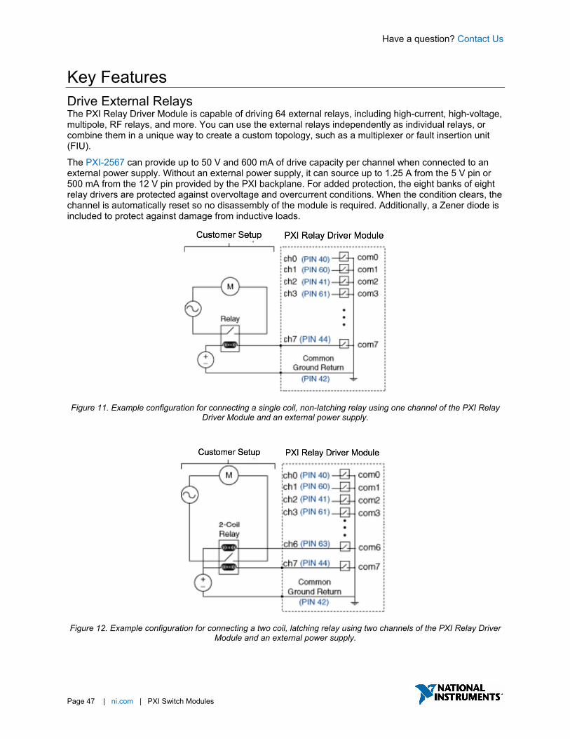
Key Features Drive External Relays The PXI Relay Driver Module is capable of driving 64 external relays, including high-current, high-voltage, multipole, RF relays, and more. You can use the external relays independently as individual relays, or combine them in a unique way to create a custom topology, such as a multiplexer or fault insertion unit (FIU).
The PXI-2567 can provide up to 50 V and 600 mA of drive capacity per channel when connected to an external power supply. Without an external power supply, it can source up to 1.25 A from the 5 V pin or 500 mA from the 12 V pin provided by the PXI backplane. For added protection, the eight banks of eight relay drivers are protected against overvoltage and overcurrent conditions. When the condition clears, the channel is automatically reset so no disassembly of the module is required. Additionally, a Zener diode is included to protect against damage from inductive loads.
Figure 11. Example configuration for connecting a single coil, non-latching relay using one channel of the PXI Relay
Driver Module and an external power supply.
Figure 12. Example configuration for connecting a two coil, latching relay using two channels of the PXI Relay Driver
Module and an external power supply.

Have a question? Contact Us
Page 48 | ni.com | PXI Switch Modules
Synchronization and Integration NI switches use the inherent timing and synchronization capabilities of the PXI platform to communicate with other instruments within the PXI chassis1. You can store a list of switch connections in memory onboard the switch module and then use the integrated hardware scanning and triggering engine to advance the switch sequence and rapidly communicate with any PXI instrument that can send and receive digital triggers, such as DMM or oscilloscope. This advanced switching method removes the software overhead and reduces the bus latency associated with traditional software-controlled switching operations for faster test execution with more repeatable timing.
1Triggering is available on most NI switches. To check if this feature is supported by a switch module, reference the “Trigger Characteristics” section of the product specification document.

Have a question? Contact Us
Page 49 | ni.com | PXI Switch Modules
NI-SWITCH Soft Front Panel The NI-SWITCH driver software includes an interactive soft front panel for full out-of-the-box functionality. This interactive soft front panel allows you to configure the switch topology and change switch connections with a simple click. In addition, you can use the Debug Driver Session mode to monitor and debug the switch during automated measurement. For example, you can monitor which signal paths are active, which individual relays are open/closed, and how many times each relay has been used.
NI-SWITCH Application Programming Interface (API) In addition to the soft front panel, the NI-SWITCH driver includes a best-in-class API that works with a variety of development options such as LabVIEW, C, C#, and others. The driver also provides access to help files, documentation, and dozens of ready-to-run shipping examples you can use as a starting point for your application.

Have a question? Contact Us.
Page 50 | ni.com | PXI Switch Modules
Switch Executive Application Software While the NI-SWITCH driver provides all the low-level functionality required to program switch actions, Switch Executive is application software for intelligent switch management and routing that accelerates development and simplifies maintenance of complex switch systems. The point-and-click graphical configuration and automatic routing capabilities make it easy to design your switch system. Using intuitive channel aliases and route names keeps your system documented for future modifications. Save time and increase test code reuse by integrating your system with TestStand, LabVIEW, LabWindows™ /CVI, and Measurement Studio.
• Graphically configure routes and route groups
• Develop reusable switching code and integrate it into NI TestStand or NI LabVIEW
• Automatically route signals between switch endpoints
• Scale switch configuration using Microsoft Excel
• Maintain switch configuration using route validation, reporting and debugging features
Have a question? Contact Us
Page 51 | ni.com | PXI Switch Modules
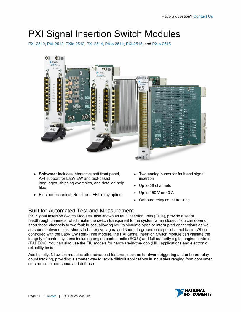
PXI Signal Insertion Switch Modules PXI-2510, PXI-2512, PXIe-2512, PXI-2514, PXIe-2514, PXI-2515, and PXIe-2515
• Software: Includes interactive soft front panel, API support for LabVIEW and text-based languages, shipping examples, and detailed help files
• Electromechanical, Reed, and FET relay options
• Two analog buses for fault and signal insertion
• Up to 68 channels
• Up to 150 V or 40 A
• Onboard relay count tracking
Built for Automated Test and Measurement PXI Signal Insertion Switch Modules, also known as fault insertion units (FIUs), provide a set of feedthrough channels, which make the switch transparent to the system when closed. You can open or short these channels to two fault buses, allowing you to simulate open or interrupted connections as well as shorts between pins, shorts to battery voltages, and shorts to ground on a per-channel basis. When controlled with the LabVIEW Real-Time Module, the PXI Signal Insertion Switch Module can validate the integrity of control systems including engine control units (ECUs) and full authority digital engine controls (FADECs). You can also use the FIU models for hardware-in-the-loop (HIL) applications and electronic reliability tests.
Additionally, NI switch modules offer advanced features, such as hardware triggering and onboard relay count tracking, providing a smarter way to tackle difficult applications in industries ranging from consumer electronics to aerospace and defense.
Have a question? Contact Us
Page 52 | ni.com | PXI Switch Modules
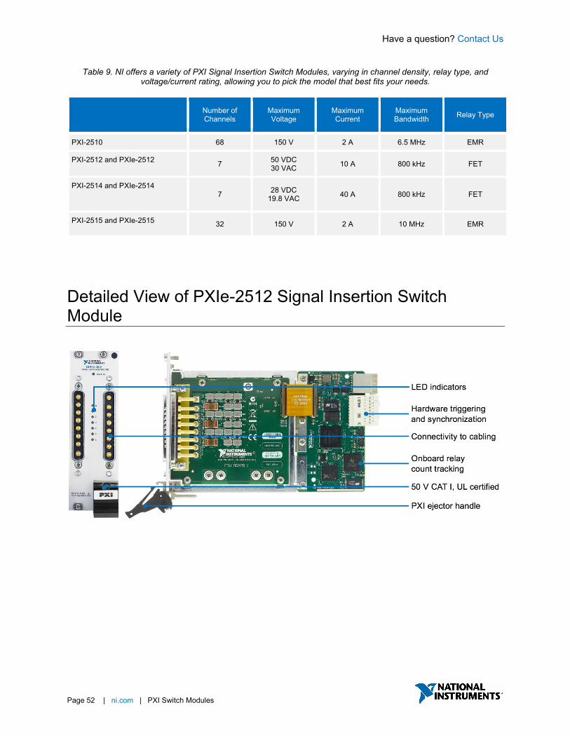
Table 9. NI offers a variety of PXI Signal Insertion Switch Modules, varying in channel density, relay type, and voltage/current rating, allowing you to pick the model that best fits your needs.
Number of Channels
Maximum Voltage
Maximum Current
Maximum Bandwidth Relay Type
PXI-2510 68 150 V 2 A 6.5 MHz EMR
PXI-2512 and PXIe-2512 7 50 VDC 30 VAC 10 A 800 kHz FET
PXI-2514 and PXIe-2514 7 28 VDC
19.8 VAC 40 A 800 kHz FET
PXI-2515 and PXIe-2515 32 150 V 2 A 10 MHz EMR
Detailed View of PXIe-2512 Signal Insertion Switch Module

Have a question? Contact Us
Page 53 | ni.com | PXI Switch Modules
Key Features Hardware Fault Insertion In many hardware-in-the-loop (HIL) test systems, hardware fault insertion or signal insertion is used to create signal faults between the electronic control unit (ECU) and the rest of the system to test, characterize, or validate ECU behavior under specific failure conditions. Fault insertion is most commonly used when it is imperative for a specific ECU to have both a known and an acceptable response to fault conditions – examples include ECUs for vehicles, aircraft, spacecraft, and machinery. To accomplish this, fault insertion units (FIUs) are inserted between the I/O interfaces of a test system and the ECU so the test system can switch between normal operation and fault conditions such as a short to battery, short to ground, or open circuit.
Figure 13. An FIU can insert fault conditions between automated test equipment, such as hardware-in-the-loop
simulation systems, and devices under test. This FIU schematic is capable of numerous example faults, including open circuit fault, short to ground, short to power, and pin-to-pin short.
Synchronization and Integration NI switches use the inherent timing and synchronization capabilities of the PXI platform to communicate with other instruments within the PXI chassis1. You can store a list of switch connections in memory onboard the switch module and then use the integrated hardware scanning and triggering engine to advance the switch sequence and rapidly communicate with any PXI instrument that can send and receive digital triggers, such as DMM or oscilloscope. This advanced switching method removes the software overhead and reduces the bus latency associated with traditional software-controlled switching operations for faster test execution with more repeatable timing.
1Triggering is available on most NI switches. To check if this feature is supported by a switch module, reference the “Trigger Characteristics” section of the product specification document.
Have a question? Contact Us
Page 54 | ni.com | PXI Switch Modules
NI-SWITCH Soft Front Panel The NI-SWITCH driver software includes an interactive soft front panel for full out-of-the-box functionality. This interactive soft front panel allows you to configure the switch topology and change switch connections with a simple click. In addition, you can use the Debug Driver Session mode to monitor and debug the switch during automated measurement. For example, you can monitor which signal paths are active, which individual relays are open/closed, and how many times each relay has been used.
NI-SWITCH Application Programming Interface (API) In addition to the soft front panel, the NI-SWITCH driver includes a best-in-class API that works with a variety of development options such as LabVIEW, C, C#, and others. The driver also provides access to help files, documentation, and dozens of ready-to-run shipping examples you can use as a starting point for your application.

Have a question? Contact Us.
Page 55 | ni.com | PXI Switch Modules
Switch Executive Application Software While the NI-SWITCH driver provides all the low-level functionality required to program switch actions, Switch Executive is application software for intelligent switch management and routing that accelerates development and simplifies maintenance of complex switch systems. The point-and-click graphical configuration and automatic routing capabilities make it easy to design your switch system. Using intuitive channel aliases and route names keeps your system documented for future modifications. Save time and increase test code reuse by integrating your system with TestStand, LabVIEW, LabWindows™ /CVI, and Measurement Studio.
• Graphically configure routes and route groups
• Develop reusable switching code and integrate it into NI TestStand or NI LabVIEW
• Automatically route signals between switch endpoints
• Scale switch configuration using Microsoft Excel
• Maintain switch configuration using route validation, reporting and debugging features
Have a question? Contact Us
Page 56 | ni.com | PXI Switch Modules
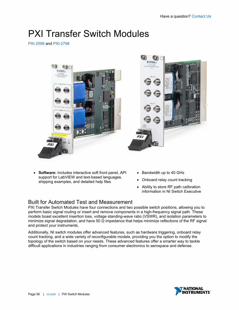
PXI Transfer Switch Modules PXI-2598 and PXI-2798
• Software: Includes interactive soft front panel, API support for LabVIEW and text-based languages, shipping examples, and detailed help files
• Bandwidth up to 40 GHz
• Onboard relay count tracking
• Ability to store RF path calibration information in NI Switch Executive
Built for Automated Test and Measurement PXI Transfer Switch Modules have four connections and two possible switch positions, allowing you to perform basic signal routing or insert and remove components in a high-frequency signal path. These models boast excellent insertion loss, voltage standing-wave ratio (VSWR), and isolation parameters to minimize signal degradation, and have 50 Ω impedance that helps minimize reflections of the RF signal and protect your instruments.
Additionally, NI switch modules offer advanced features, such as hardware triggering, onboard relay count tracking, and a wide variety of reconfigurable models, providing you the option to modify the topology of the switch based on your needs. These advanced features offer a smarter way to tackle difficult applications in industries ranging from consumer electronics to aerospace and defense.
Have a question? Contact Us
Page 57 | ni.com | PXI Switch Modules
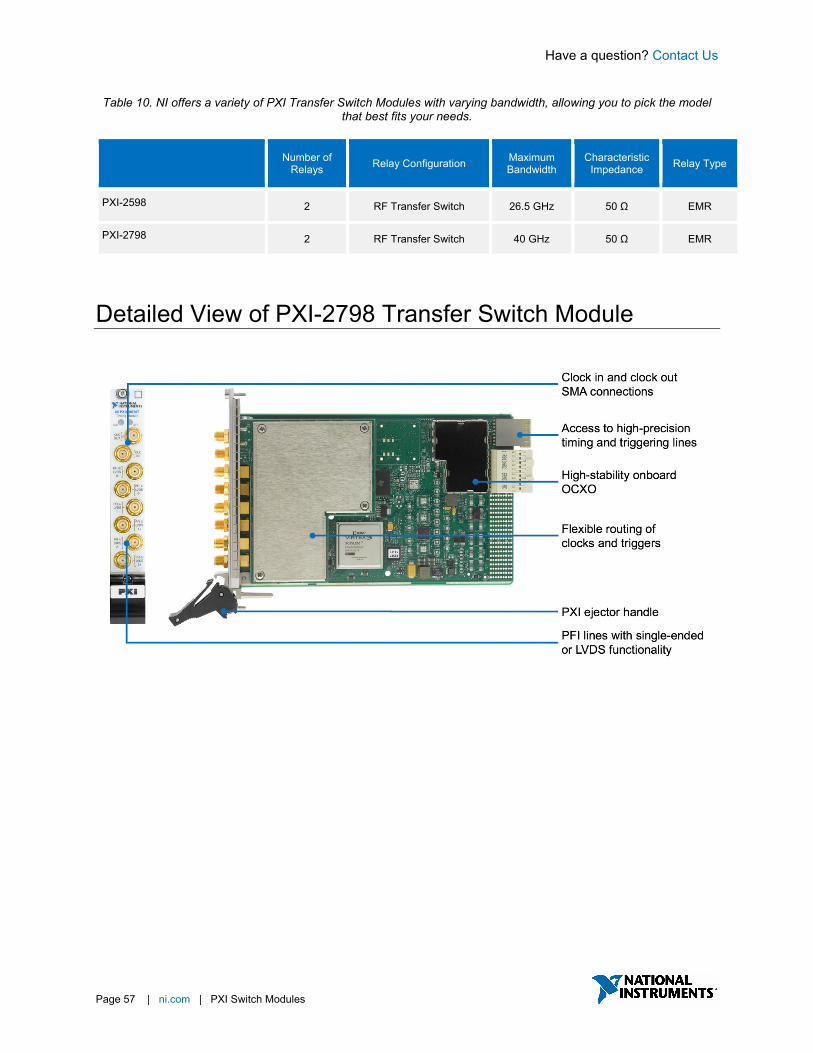
Table 10. NI offers a variety of PXI Transfer Switch Modules with varying bandwidth, allowing you to pick the model that best fits your needs.
Number of Relays Relay Configuration Maximum
Bandwidth Characteristic
Impedance Relay Type
PXI-2598 2 RF Transfer Switch 26.5 GHz 50 Ω EMR
PXI-2798 2 RF Transfer Switch 40 GHz 50 Ω EMR
Detailed View of PXI-2798 Transfer Switch Module

Have a question? Contact Us
Page 58 | ni.com | PXI Switch Modules
Key Features Synchronization and Integration NI switches use the inherent timing and synchronization capabilities of the PXI platform to communicate with other instruments within the PXI chassis1. You can store a list of switch connections in memory onboard the switch module and then use the integrated hardware scanning and triggering engine to advance the switch sequence and rapidly communicate with any PXI instrument that can send and receive digital triggers, such as DMM or oscilloscope. This advanced switching method removes the software overhead and reduces the bus latency associated with traditional software-controlled switching operations for faster test execution with more repeatable timing.
1Triggering is available on most NI switches. To check if this feature is supported by a switch module, reference the “Trigger Characteristics” section of the product specification document.
Have a question? Contact Us
Page 59 | ni.com | PXI Switch Modules
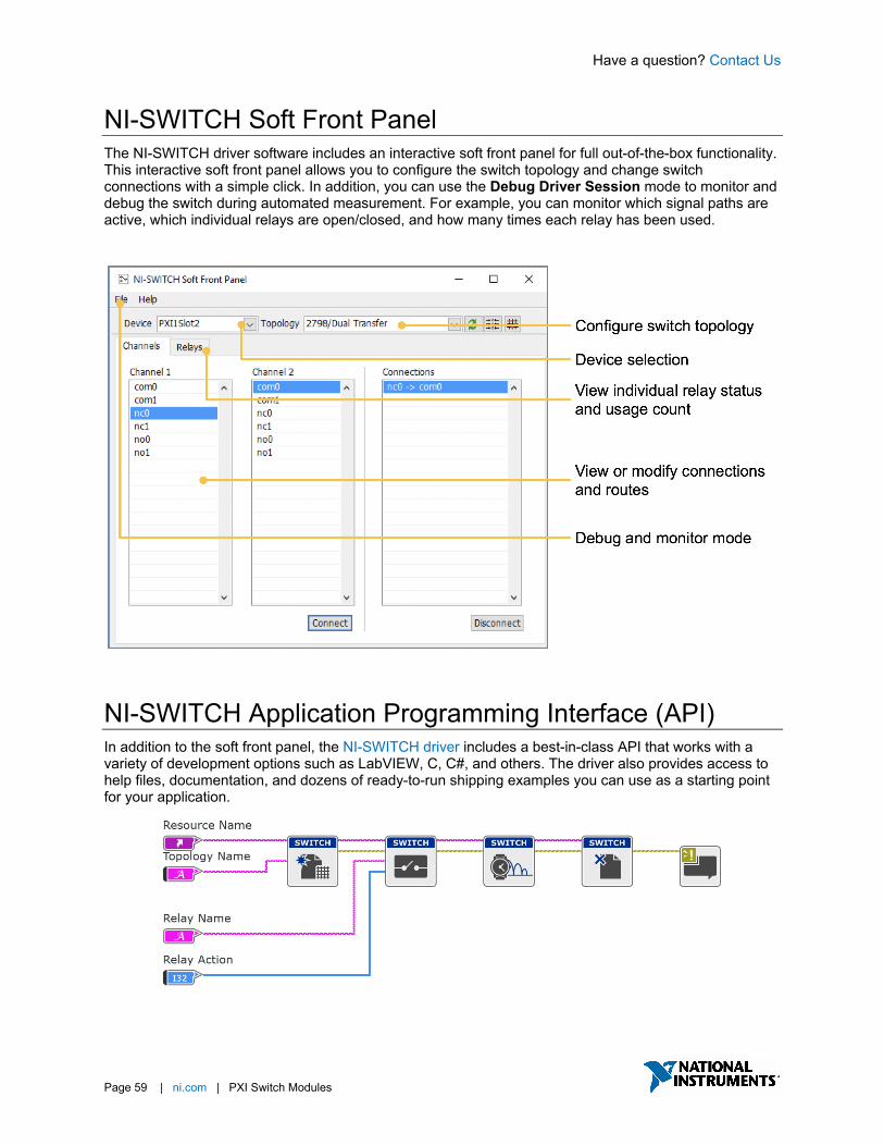
NI-SWITCH Soft Front Panel The NI-SWITCH driver software includes an interactive soft front panel for full out-of-the-box functionality. This interactive soft front panel allows you to configure the switch topology and change switch connections with a simple click. In addition, you can use the Debug Driver Session mode to monitor and debug the switch during automated measurement. For example, you can monitor which signal paths are active, which individual relays are open/closed, and how many times each relay has been used.
NI-SWITCH Application Programming Interface (API) In addition to the soft front panel, the NI-SWITCH driver includes a best-in-class API that works with a variety of development options such as LabVIEW, C, C#, and others. The driver also provides access to help files, documentation, and dozens of ready-to-run shipping examples you can use as a starting point for your application.
Have a question? Contact Us.
Page 60 | ni.com | PXI Switch Modules
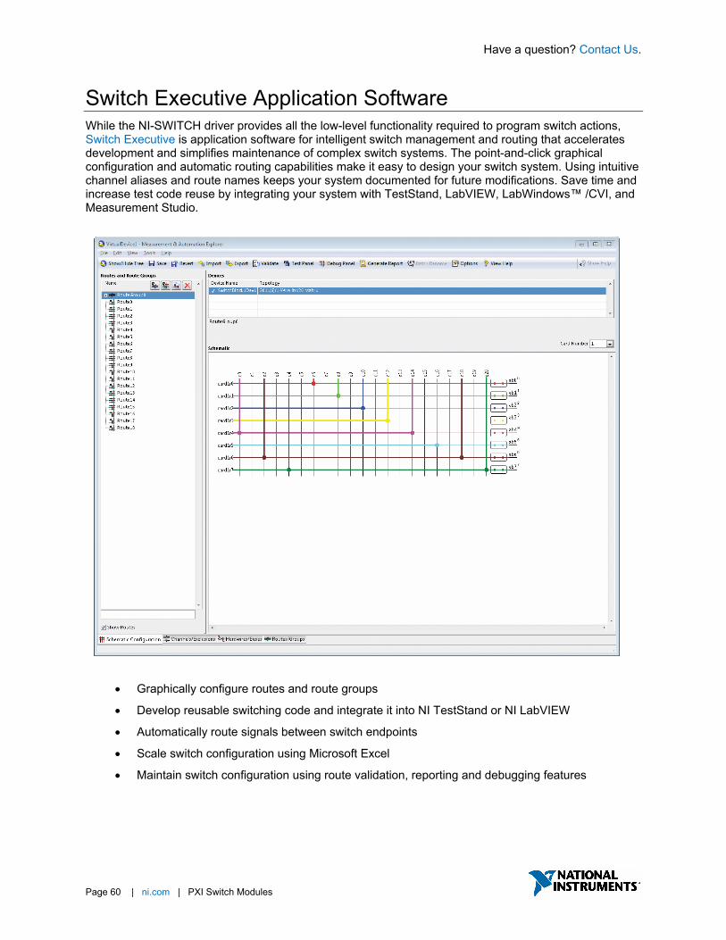
Switch Executive Application Software While the NI-SWITCH driver provides all the low-level functionality required to program switch actions, Switch Executive is application software for intelligent switch management and routing that accelerates development and simplifies maintenance of complex switch systems. The point-and-click graphical configuration and automatic routing capabilities make it easy to design your switch system. Using intuitive channel aliases and route names keeps your system documented for future modifications. Save time and increase test code reuse by integrating your system with TestStand, LabVIEW, LabWindows™ /CVI, and Measurement Studio.
• Graphically configure routes and route groups
• Develop reusable switching code and integrate it into NI TestStand or NI LabVIEW
• Automatically route signals between switch endpoints
• Scale switch configuration using Microsoft Excel
• Maintain switch configuration using route validation, reporting and debugging features
Have a question? Contact Us
Page 61 | ni.com | PXI Switch Modules
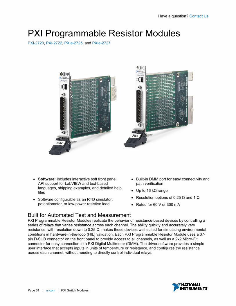
PXI Programmable Resistor Modules PXI-2720, PXI-2722, PXIe-2725, and PXIe-2727
• Software: Includes interactive soft front panel, API support for LabVIEW and text-based languages, shipping examples, and detailed help files
• Software configurable as an RTD simulator, potentiometer, or low-power resistive load
• Built-in DMM port for easy connectivity and path verification
• Up to 16 kΩ range
• Resolution options of 0.25 Ω and 1 Ω
• Rated for 60 V or 300 mA
Built for Automated Test and Measurement PXI Programmable Resistor Modules replicate the behavior of resistance‐based devices by controlling a series of relays that varies resistance across each channel. The ability quickly and accurately vary resistance, with resolution down to 0.25 Ω, makes these devices well‐suited for simulating environmental conditions in hardware‐in‐the‐loop (HIL) validation. Each PXI Programmable Resistor Module uses a 37‐pin D‐SUB connector on the front panel to provide access to all channels, as well as a 2x2 Micro‐Fit connector for easy connection to a PXI Digital Multimeter (DMM). The driver software provides a simple user interface that accepts inputs in units of temperature or resistance, and configures the resistance across each channel, without needing to directly control individual relays.
Have a question? Contact Us
Page 62 | ni.com | PXI Switch Modules
Table 11. NI offers a variety of PXI Programmable Resistor Modules, varying in resistance range, resolution, and density, allowing you to pick the model that best fits your needs.
Number of Channels
Maximum Resistance Resolution Maximum Voltage Maximum Current
PXI-2720 10 255 Ω 1 Ω 60 V 300 mA
PXI-2722 5 16 kΩ 0.25 Ω 60 V 300 mA
PXIe-2725 18 255 Ω 1 Ω 60 V 300 mA
PXIe-2727 9 16 kΩ 0.25 Ω 60 V 300 mA
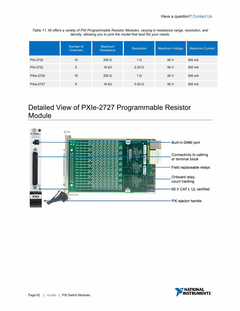
Detailed View of PXIe-2727 Programmable Resistor Module
Have a question? Contact Us
Page 63 | ni.com | PXI Switch Modules
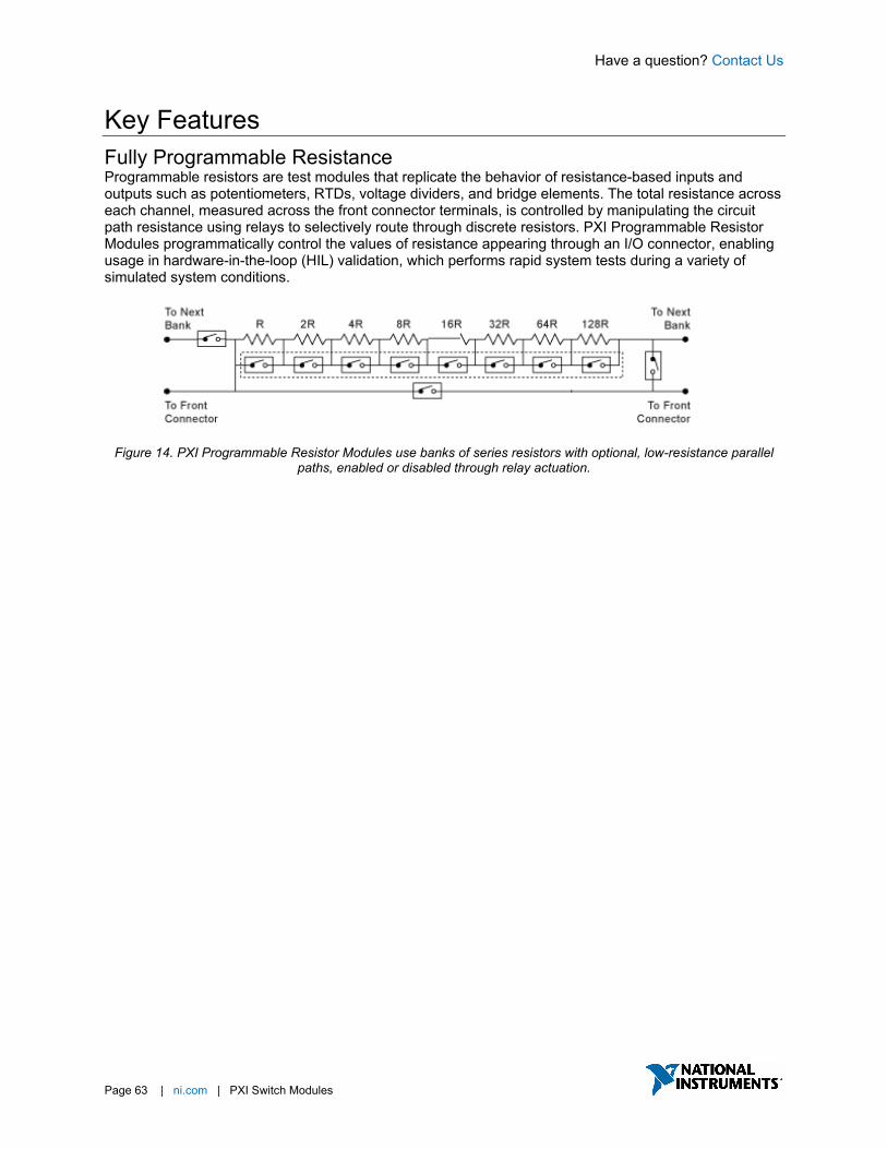
Key Features Fully Programmable Resistance Programmable resistors are test modules that replicate the behavior of resistance-based inputs and outputs such as potentiometers, RTDs, voltage dividers, and bridge elements. The total resistance across each channel, measured across the front connector terminals, is controlled by manipulating the circuit path resistance using relays to selectively route through discrete resistors. PXI Programmable Resistor Modules programmatically control the values of resistance appearing through an I/O connector, enabling usage in hardware-in-the-loop (HIL) validation, which performs rapid system tests during a variety of simulated system conditions.
Figure 14. PXI Programmable Resistor Modules use banks of series resistors with optional, low-resistance parallel
paths, enabled or disabled through relay actuation.

Have a question? Contact Us
Page 64 | ni.com | PXI Switch Modules
NI-SWITCH Soft Front Panel The NI-SWITCH driver software includes an interactive soft front panel for full out-of-the-box functionality. This interactive soft front panel allows you to select the device and open or close individual relays with a simple click. In addition, you can use the Debug Driver Session mode to monitor and debug the device during automated measurement. For example, you can monitor which individual relays are open/closed and how many times each relay has been used, while a LabVIEW application uses the same device in an automated application.
Have a question? Contact Us
Page 65 | ni.com | PXI Switch Modules
NI-SWITCH Application Programming Interface (API) In addition to the soft front panel, the NI-SWITCH driver includes a best-in-class API that works with a variety of development options such as LabVIEW, C, C#, and others, allowing you to control individual relays within the PXI Programmable Resistor Module. The driver also provides access to help files, documentation, and dozens of ready-to-run shipping examples you can use as a starting point for your application.
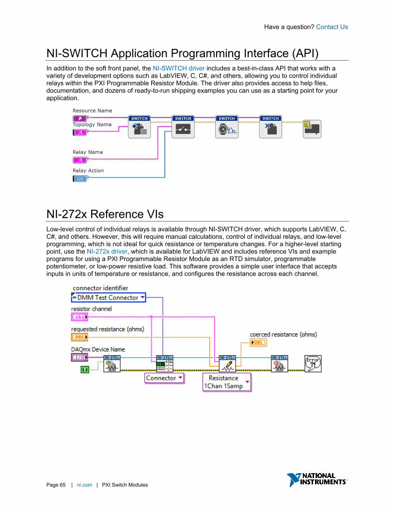
NI-272x Reference VIs Low-level control of individual relays is available through NI-SWITCH driver, which supports LabVIEW, C, C#, and others. However, this will require manual calculations, control of individual relays, and low-level programming, which is not ideal for quick resistance or temperature changes. For a higher-level starting point, use the NI-272x driver, which is available for LabVIEW and includes reference VIs and example programs for using a PXI Programmable Resistor Module as an RTD simulator, programmable potentiometer, or low-power resistive load. This software provides a simple user interface that accepts inputs in units of temperature or resistance, and configures the resistance across each channel.
Have a question? Contact Us
Page 66 | ni.com | PXI Switch Modules
Switch Executive Application Software While the NI-SWITCH driver provides all the low-level functionality required to program switch actions, Switch Executive is application software for intelligent switch management and routing that accelerates development and simplifies maintenance of complex switch systems. The point-and-click graphical configuration and automatic routing capabilities make it easy to design your switch system. Using intuitive channel aliases and route names keeps your system documented for future modifications. Save time and increase test code reuse by integrating your system with TestStand, LabVIEW, LabWindows™ /CVI, and Measurement Studio.
• Graphically configure routes and route groups
• Develop reusable switching code and integrate it into NI TestStand or NI LabVIEW
• Automatically route signals between switch endpoints
• Scale switch configuration using Microsoft Excel
• Maintain switch configuration using route validation, reporting and debugging features
Have a question? Contact Us
Page 67 | ni.com | PXI Switch Modules
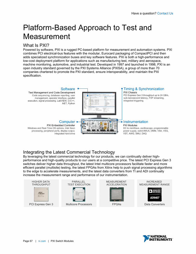
Platform-Based Approach to Test and Measurement What Is PXI? Powered by software, PXI is a rugged PC-based platform for measurement and automation systems. PXI combines PCI electrical-bus features with the modular, Eurocard packaging of CompactPCI and then adds specialized synchronization buses and key software features. PXI is both a high-performance and low-cost deployment platform for applications such as manufacturing test, military and aerospace, machine monitoring, automotive, and industrial test. Developed in 1997 and launched in 1998, PXI is an open industry standard governed by the PXI Systems Alliance (PXISA), a group of more than 70 companies chartered to promote the PXI standard, ensure interoperability, and maintain the PXI specification.
Integrating the Latest Commercial Technology By leveraging the latest commercial technology for our products, we can continually deliver high-performance and high-quality products to our users at a competitive price. The latest PCI Express Gen 3 switches deliver higher data throughput, the latest Intel multicore processors facilitate faster and more efficient parallel (multisite) testing, the latest FPGAs from Xilinx help to push signal processing algorithms to the edge to accelerate measurements, and the latest data converters from TI and ADI continually increase the measurement range and performance of our instrumentation.

Have a question? Contact Us
Page 68 | ni.com | PXI Switch Modules
PXI Instrumentation NI offers more than 600 different PXI modules ranging from DC to mmWave. Because PXI is an open industry standard, nearly 1,500 products are available from more than 70 different instrument vendors. With standard processing and control functions designated to a controller, PXI instruments need to contain only the actual instrumentation circuitry, which provides effective performance in a small footprint. Combined with a chassis and controller, PXI systems feature high-throughput data movement using PCI Express bus interfaces and sub-nanosecond synchronization with integrated timing and triggering.
Oscilloscopes Sample at speeds up to 12.5 GS/s with 5 GHz of analog bandwidth, featuring numerous triggering modes and deep onboard memory
Digital Instruments Perform characterization and production test of semiconductor devices with timing sets and per channel pin parametric measurement unit (PPMU)
Frequency Counters Perform counter timer tasks such as event counting and encoder position, period, pulse, and frequency measurements
Power Supplies & Loads Supply programmable DC power, with some modules including isolated channels, output disconnect functionality, and remote sense
Switches (Matrix & MUX) Feature a variety of relay types and row/column configurations to simplify wiring in automated test systems
GPIB, Serial, & Ethernet Integrate non-PXI instruments into a PXI system through various instrument control interfaces
Digital Multimeters Perform voltage (up to 1000 V), current (up to 3A), resistance, inductance, capacitance, and frequency/period measurements, as well as diode tests
Waveform Generators Generate standard functions including sine, square, triangle, and ramp as well as user-defined, arbitrary waveforms
Source Measure Units Combine high-precision source and measure capability with high channel density, deterministic hardware sequencing, and SourceAdapt transient optimization
FlexRIO Custom Instruments & Processing Provide high-performance I/O and powerful FPGAs for applications that require more than standard instruments can offer
Vector Signal Transceivers Combine a vector signal generator and vector signal analyzer with FPGA-based, real-time signal processing and control
Data Acquisition Modules Provide a mix of analog I/O, digital I/O, counter/timer, and trigger functionality for measuring electrical or physical phenomena

Have a question? Contact Us
©2017 National Instruments. All rights reserved. LabVIEW, National Instruments, NI, NI TestStand, and ni.com are trademarks of National Instruments. Other product and company names listed are trademarks or trade names of their respective companies. The contents of this Site could contain technical inaccuracies, typographical errors or out-of-date information. Information may be updated or changed at any time, without notice. Visit ni.com/manuals for the latest information.
25 July 2017 Page 69 | ni.com | PXI Switch Modules
Hardware Services All NI hardware includes a one-year warranty for basic repair coverage, and calibration in adherence to NI specifications prior to shipment. PXI Systems also include basic assembly and a functional test. NI offers additional entitlements to improve uptime and lower maintenance costs with service programs for hardware. Learn more at ni.com/services/hardware.
Standard Premium Description
Program Duration 3 or 5 years 3 or 5 years Length of service program
Extended Repair Coverage NI restores your device’s functionality and includes firmware updates and
factory calibration.
System Configuration, Assembly, and Test1
NI technicians assemble, install software in, and test your system per your custom configuration prior to shipment.
Advanced Replacement2 NI stocks replacement hardware that can be shipped immediately if a repair
is needed.
System RMA1 NI accepts the delivery of fully assembled systems when performing repair services.
Calibration Plan (Optional) Standard Expedited3 NI performs the requested level of calibration at the specified calibration
interval for the duration of the service program.
1This option is only available for PXI, CompactRIO, and CompactDAQ systems. 2This option is not available for all products in all countries. Contact your local NI sales engineer to confirm availability. 3Expedited calibration only includes traceable levels.
PremiumPlus Service Program NI can customize the offerings listed above, or offer additional entitlements such as on-site calibration, custom sparing, and life-cycle services through a PremiumPlus Service Program. Contact your NI sales representative to learn more.
Technical Support Every NI system includes a 30-day trial for phone and e-mail support from NI engineers, which can be extended through a Software Service Program (SSP) membership. NI has more than 400 support engineers available around the globe to provide local support in more than 30 languages. Additionally, take advantage of NI’s award winning online resources and communities.