purge/pressurization system data sheets - series...
TRANSCRIPT

SERIES 2000 DATA SHEETS
PROCESS AUTOMATION
PURGE/PRESSURIZATION SYSTEM

Type X
2000SERIES
2
Type X
Type X Systems (2000 Series) 2001A:ClassIEnclosureVolumes≤2ft3andClassIIEnclosureVolumes≤10ft3.................................3 2001B:ClassIIEnclosureVolumes≤50ft3............................................................................................7 2001C:ClassIIEnclosureVolumes≤250ft3.........................................................................................11 2002:ClassIEnclosureVolumes≤15ft3..............................................................................................15 2003:ClassIEnclosureVolumes≤75ft3...............................................................................................19 2004:ClassIEnclosureVolumes≤200ft3.............................................................................................23 2005:ClassIEnclosureVolumes≤450ft3.............................................................................................37
Accessories.......................................................................................................................................................31
Type X
2000SERIES
3
Type X
Description
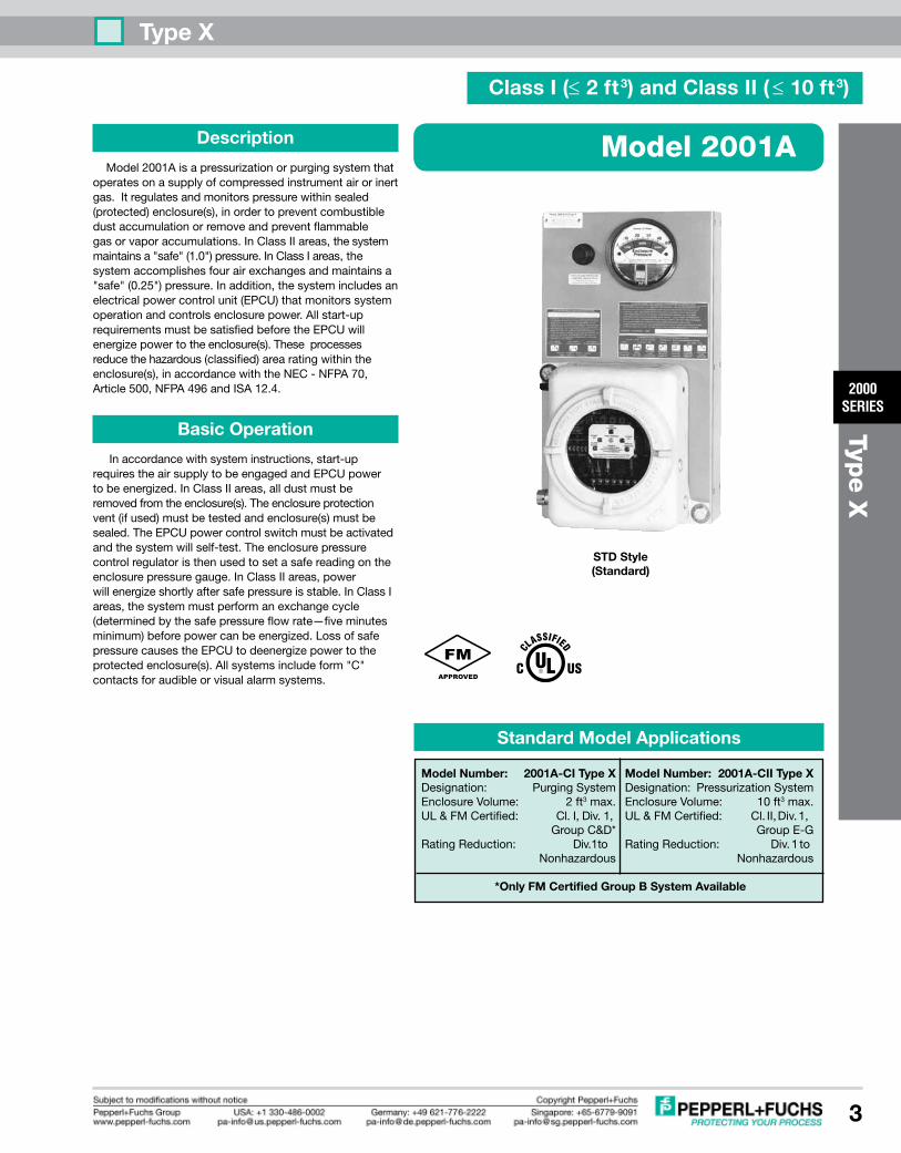
Model2001Aisapressurizationorpurgingsystemthatoperatesonasupplyofcompressedinstrumentairorinertgas.Itregulatesandmonitorspressurewithinsealed(protected)enclosure(s),inordertopreventcombustibledustaccumulationorremoveandpreventflammablegasorvaporaccumulations.InClassIIareas,thesystemmaintainsa"safe"(1.0")pressure.InClassIareas,thesystemaccomplishesfourairexchangesandmaintainsa"safe"(0.25")pressure.Inaddition,thesystemincludesanelectricalpowercontrolunit(EPCU)thatmonitorssystemoperationandcontrolsenclosurepower.Allstart-uprequirementsmustbesatisfiedbeforetheEPCUwillenergizepowertotheenclosure(s).Theseprocessesreducethehazardous(classified)arearatingwithintheenclosure(s),inaccordancewiththeNEC-NFPA70,Article500,NFPA496andISA12.4.
Basic Operation
Inaccordancewithsysteminstructions,start-uprequirestheairsupplytobeengagedandEPCUpowertobeenergized.InClassIIareas,alldustmustberemovedfromtheenclosure(s).Theenclosureprotectionvent(ifused)mustbetestedandenclosure(s)mustbesealed.TheEPCUpowercontrolswitchmustbeactivatedandthesystemwillself-test.Theenclosurepressurecontrolregulatoristhenusedtosetasafereadingontheenclosurepressuregauge.InClassIIareas,powerwillenergizeshortlyaftersafepressureisstable.InClassIareas,thesystemmustperformanexchangecycle(determinedbythesafepressureflowrate—fiveminutesminimum)beforepowercanbeenergized.LossofsafepressurecausestheEPCUtodeenergizepowertotheprotectedenclosure(s).Allsystemsincludeform"C"contactsforaudibleorvisualalarmsystems.
Model 2001A
STD Style (Standard)
Model Number: 2001A-CII Type XDesignation: PressurizationSystemEnclosureVolume: 10ft3max.UL&FMCertified: Cl.II,Div.1, GroupE-GRatingReduction: Div.1to Nonhazardous
Model Number: 2001A-CI Type XDesignation: PurgingSystemEnclosureVolume: 2ft3max.UL&FMCertified: Cl.I,Div.1, GroupC&D*RatingReduction: Div.1to Nonhazardous
Standard Model Applications
*Only FM Certified Group B System Available
Class I (≤ 2 ft3) and Class II ( ≤ 10 ft3)

Type X
2000SERIES
4
Type X
System SupplyInlet
Regulator
Enclosure SupplyOutlet
MountingPlate
FlameArrestorFitting
VenturiOrifice
System Specifications
SystemDimensions: Seepage6ShippingWeight: 38lbTemp.Range: -20°Fto+120°FSupplyPressureRange: *5-120psimax.SupplyRequirements: CleanairorinertgasSafePress.Setpoint(CI/CII): 0.25"/1.0"SafePress.FlowRate: **0.1-3.5SCFHClassIExchangeTime: ***AsrequiredSystemSupplyPort: 1/4"TubeFittingEnclosureSupplyFitting: 1/4"TubeFittingEnclosureReferenceFitting: 1/4"TubeFittingEPCUConduitPortSize: 1/2"FPTEPCUPowerRequirements: 120VAC60Hz1Ø(European240voltageonly) 240VAC50Hz1Ø(Allvoltageratingsarefactoryset)EPCUPowerConsumption: 500mAPowerRelayContacts: 20A@240VAC 20A@28VDC ****[email protected]: 20A@240VAC [email protected]: 15A@240VAC 10A@2VDC
* WithEPV-1Vent-120psimax.to5psimin.SystemsinstalledwithoutVentmustbeequippedwithtamperproofregulatorsetto5psimax.
** Enclosureintegritydeterminesactualflowrate
*** Timerequiredtoexchange4volumeswithintheenclosure(s),basedonactualmeasuredsafepressureflowrateor5minutes,whicheverisgreater
EPCU Description
ThePepperl+Fuchs2000SeriesEPCUisafactoryprogrammed,fieldadjustable,microprocessorcontrolledunitfeaturingfullstatusindication,redundantgatearraylogicandelectromechanicalrelays.TheEPCUisconstructedfromfourmajoritems:(1)apowermodule,(2)apressureswitchmodule,(3)alogicmoduleand(4)apowermodeselectorswitch.Thesectionsarelinkedwithpolarizedcable,andtheboardsarestackedintheEPCUenclosureonstandoffs.
Basic EPCU Operation
Whenpoweris"off",theEPCUisatrest,alarmandpowerrelaysaredeenergized,andtheLEDdisplayisoff.Whenpowerisswitched"on",theEPCUperformsaself-testofLEDdisplayandlogicfunctions.Theunitwillthenstart-up.ClassIIunitsmustdetecta0.50"pressuretoenergizethealarmrelay.Theenclosurepowerrelaysenergizeafterabriefdelay.ClassIunitsmustdetecta0.25"pressuretoenergizethealarmrelayandbeginanexchangecycle.Whenthecyclestops,thepowerrelayswillenergize.Lossofsafepressureoneitherunitcausesalarmandpowerrelaystodeenergize(seepowercontroloptionsformoreinformationregardingEPCUoperation).
EnclosureReference Inlet
EnclosurePressureGauge
EPCUPressureReferenceTubing
STD Style
Material Specifications
RegulatorBody: Zincw/EnamelFinishRegulatorHandle: PolycarbonateEnclosurePressureGauge: Alum.w/EnamelFinishTubeFittings: 316SSForgedBodyTubing: 316SS1/4".035WeldedSystemNameplates: SilkscreenedLexan®&SSFastenerHardware: SSScrews&BoltsMountingPlate: 31614Ga#3BrushSSEPCUEnclosureBody: BeadBlastCastAlum.EnclosureWarningNameplate: SilkscreenedSS
Lexan®isaregisteredtrademarkoftheGeneralElectricCorporation
Electrical Wiring Diagram
Simplified EPCU Redundant Logic Diagram
PER
GAL
CLK
FAIL
PR
C
(2)
SPCR
µPSPS
(1)
(3)
EPR
EPR
SPS - SAFE PRESSURE SWITChGAL - GATE ARRAy LOGICµP - MICROPROCESSORPER - POWER ENABLED RELAySPCR - SAFE PRESSURE CONFIRMATION RELAyEPR - ENCLOSURE POWER RELAy
OPERATION
Signal(1)fromSPSissenttoµP,GALandSPCRcoil.Duringstart-up,GALverifiesallµPfunctions.GAL&µPmustreceiveuninterruptedsignalfromSPStopreventlogicresetting.AfterGALverifiesallstart-upprocedures,itsends"powerenabled"signal(2)toPERcoil.Then,µPsends"powerrequest"signal(3)throughtheSPCRandPERcontactstoEPRcoils.
Remote AlarmRelay Terminals
12345678910
NO Com NC
OutInIn Out
Enclosure Power Supply
Terminals
IsolatedEnclosure
PowerRelays
IsolatedAlarmRelayField Wired
Power ModuleTerminals 20A
FUSES
EPCU PowerSupply Terminals
120VAC240VAC(OptionalVoltage)
NeuNeu
HotHot
GndGnd
CONNECTION POINTS SHOWN ABOVE IN BOLD TEXT ON SYSTEM DIAGRAM

Type X
2000SERIES
5
Type X
PowerModuleWiringTerminal
20AEnclosurePowerFuse
VoltageInputSelectorHeader(factorysetfor120or240VACpower)
RESVFactoryWiringTerminal
PressureSwitchCableHeader
LogicModuleCableHeader
RedundantSafePressureRelay
20AEnclosurePowerRelays
20AAlarmRelay
VoltageRegulatorsPowerControlSwitchCableHeader
IsolatedCoilVoltageTransformer
120/240 VAC EPCU Power Module
EPCU Pressure Switch Module
PrimarySafePressureSwitch
InputFuse
RESVRelay
SpaceforOptionalRedundantSafePressureSwitch
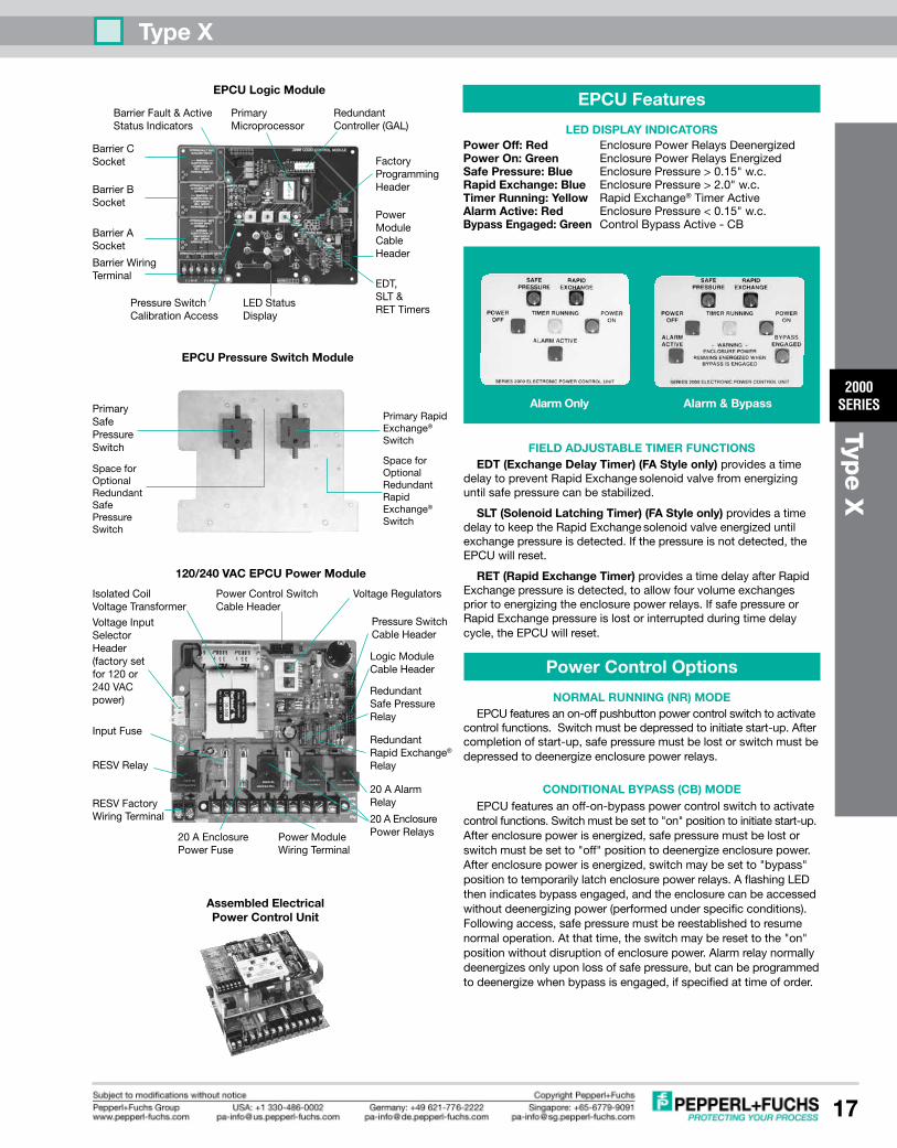
EPCU Features
LED DISPLAy INDICATORSPower Off:Red EnclosurePowerRelaysDeenergizedPower On: Green EnclosurePowerRelaysEnergizedSafe Pressure: Blue EnclosurePressure>0.15"or0.50"w.c.Timer Running:yellow ExchangeTimerActive-ClassIOnlyAlarm Active:Red EnclosurePressure<0.15"or0.50"w.c.Bypass Engaged: Green ControlBypassActive-CBModes
FIELD ADJUSTABLE TIMER FUNCTIONS RET(RapidExchangeTimer)providesatimedelayaftersafepressureisdetected,toallowfourvolumeexchangespriortoenergizingtheenclosurepowerrelays.InClassIareasonly,ifsafepressureislostduringtimedelaycycle,EPCUwillreset.
NOTE: EDT & SLT timers not functional on Series 2001 Systems
Power Control Options
NORMAL RUNNING (NR) MODE EPCUfeaturesanon-offpushbuttonpowercontrolswitchtoacti-vatecontrolfunctions.Switchmustbedepressedtoinitiatestart-up.Aftercompletionofstart-up,safepressuremustbelostorswitchmustbedepressedtodeenergizeenclosurepowerrelays.
CONDITIONAL ByPASS (CB) MODE EPCUfeaturesanoff-on-bypasspowercontrolswitchtoactivatecontrolfunctions.Switchmustbesetto"on"positiontoinitiatestart-up.Afterenclosurepowerisenergized,safepressuremustbelostorswitchmustbesetto"off"positiontodeenergizeenclosurepower.Afterenclosurepowerisenergized,switchmaybesetto"bypass"positiontotemporarilylatchenclosurepowerrelays.AflashingLEDthenindicatesbypassengaged,andtheenclosurecanthenbeaccessedwithoutdeenergizingpower(performedunderspecificconditions).Followingaccess,safepressuremustbereestablishedtoresumenormaloperation.Atthattime,theswitchmayberesettothe"on"positionwithoutdisruptionofenclosurepower.Alarmrelaynormallydeenergizesonlyuponlossofsafepressure,butcanbeprogrammedtodeenergizewhenbypassisengaged,ifspeci-fiedattimeoforder.
Class I LED Displays
Alarm Only Alarm & Bypass
BarrierFault&ActiveStatusIndicators
PrimaryMicroprocessor
FactoryProgrammingHeader
LEDStatusDisplay
PressureSwitchCalibrationAccess
BarrierASocket
BarrierBSocket
BarrierCSocket
BarrierWiringTerminal
RedundantController(GAL)
PowerModuleCableHeader
EDT,SLT&RETTimers
EPCU Logic Module
Class II LED Displays
Alarm Only Alarm & Bypass
Assembled Electrical Power Control Unit

Type X
2000SERIES
6
Type X
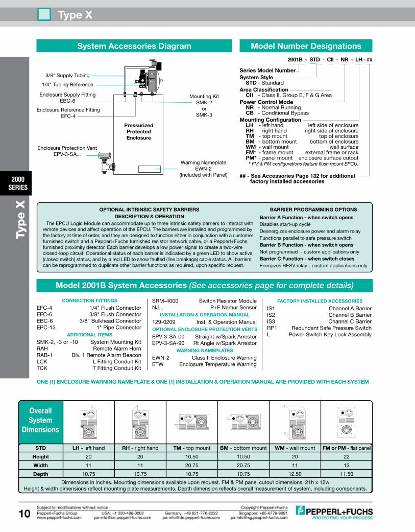
Model Number Designations
2001A - STD - CI - NR - Lh - ##
Series Model NumberSystem Style STD - StandardArea Classification CI -ClassI,GroupC&DArea CII -ClassII,GroupE,F&GArea IB -ClassI,GroupBAreaPower Control Mode NR -NormalRunning CB -ConditionalBypassMounting Configuration Lh -lefthand leftsideofenclosure Rh -righthand rightsideofenclosure TM -topmount topofenclosure BM -bottommount bottomofenclosure WM -wallmount wallsurface FM* -framemount externalframeorrack PM* -panelmount enclosuresurfacecutout* FM & PM configurations feature flush mount EPCU. Flush mount EPCU is not suitable for Group B Area.## - See Accessories Page 132 for additional factory installed accessories
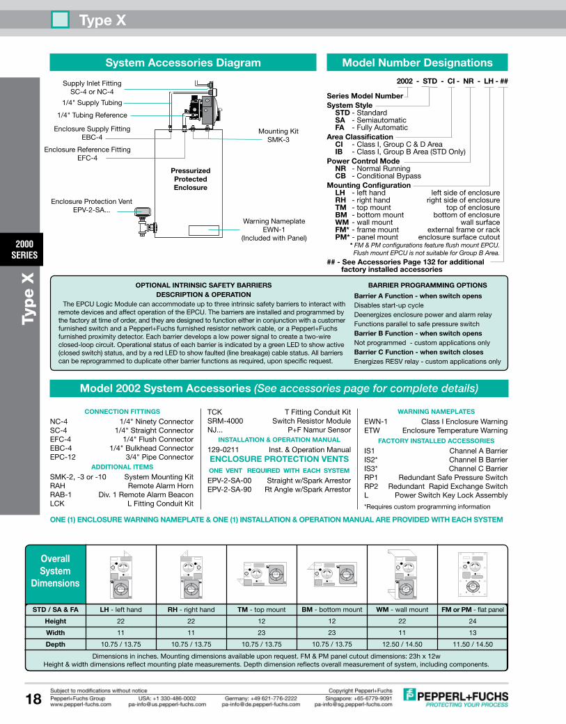
BARRIER PROGRAMMING OPTIONS
Barrier A Function - when switch opens Disablesstart-upcycleDeenergizesenclosurepowerandalarmrelayFunctionsparalleltosafepressureswitchBarrier B Function - when switch opensNotprogrammed-customapplicationsonlyBarrier C Function - when switch closesEnergizesRESVrelay-customapplicationsonly
OPTIONAL INTRINSIC SAFETy BARRIERSDESCRIPTION & OPERATION
TheEPCULogicModulecanaccommodateuptothreeintrinsicsafetybarrierstointeractwithremotedevicesandaffectoperationoftheEPCU.Thebarriersareinstalledandprogrammedbythefactoryattimeoforder,andtheyaredesignedtofunctioneitherinconjunctionwithacustomerfurnishedswitchandaPepperl+Fuchsfurnishedresistornetworkcable,oraPepperl+Fuchsfurnishedproximitydetector.Eachbarrierdevelopsalowpowersignaltocreateatwo-wireclosed-loopcircuit.OperationalstatusofeachbarrierisindicatedbyagreenLEDtoshowactive(closedswitch)status,andbyaredLEDtoshowfaulted(linebreakage)cablestatus.Allbarrierscanbereprogrammedtoduplicateotherbarrierfunctionsasrequired,uponspecificrequest.
Dimensionsininches.Mountingdimensionsavailableuponrequest.FM&PMpanelcutoutdimensions:21hx12wHeight&widthdimensionsreflectmountingplatemeasurements.Depthdimensionreflectsoverallmeasurementofsystem,includingcomponents.
OverallSystem
Dimensions
FM or PM -flatpanel
22
13
11.25
Lh -lefthand
20
11
10.50
STD
height
Width
Depth
Rh -righthand
20
11
10.50
BM -bottommount
10.50
20.75
10.50
WM-wallmount
20
11
12.50
TM -topmount
10.50
20.75
10.50
`
Model 2001A System Accessories (See accessories page for complete details)
CONNECTION FITTINGS
EFC-4 1/4"FlushConnectorEBC-4 1/4"BulkheadConnectorEPC-10 1/2"PipeConnector
ADDITIONAL ITEMS
LLF 1/4"FilterSMK-2,-3or-10 SystemMountingKitRAH RemoteAlarmHornRAB-1 Div.1RemoteAlarmBeaconLCK LFittingConduitKitTCK TFittingConduitKit
SRM-4000 SwitchResistorModuleNJ... P+FNamurSensor
INSTALLATION & OPERATION MANUAL
129-0208 Inst.&OperationManualOPTIONAL ENCLOSURE PROTECTION VENTS
EPV-1-SA-00 Straightw/SparkArrestorEPV-1-SA-90 RtAnglew/SparkArrestor
OPTIONAL hEX KEy REGULATOR hANDLE
TR-10G TamperProofRegulator
WARNING NAMEPLATES
EWN-1 ClassIEnclosureWarningEWN-2 ClassIIEnclosureWarningETW EnclosureTemperatureWarning
FACTORy INSTALLED ACCESSORIES
IS1 ChannelABarrierIS2 ChannelBBarrierIS3 ChannelCBarrierRP1 RedundantSafePressureSwitchL PowerSwitchKeyLockAssembly
ONE (1) ENCLOSURE WARNING NAMEPLATE & ONE (1) INSTALLATION & OPERATION MANUAL ARE PROVIDED WITh EACh SySTEM
1/4"SupplyTubing
MountingKitSMK-2
orSMK-3
EnclosureProtectionVentEPV-1-SA...
(EPV vent not required when using the TR-10G tamper proof regulator
as redundancy)
PressurizedProtectedEnclosure
1/4"TubingReference
EnclosureSupplyFittingEBC-4
EnclosureReferenceFittingEFC-4
System Accessories Diagram
WarningNameplateEWN-__
(IncludedwithPanel)
Type X
2000SERIES
7
Type X
Description
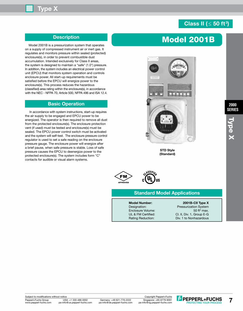
Model2001Bisapressurizationsystemthatoperatesonasupplyofcompressedinstrumentairorinertgas.Itregulatesandmonitorspressurewithinsealed(protected)enclosure(s),inordertopreventcombustibledustaccumulation.IntendedexclusivelyforClassIIareas,thesystemisdesignedtomaintaina"safe"(1.0")pressure.Inaddition,thesystemincludesanelectricalpowercontrolunit(EPCU)thatmonitorssystemoperationandcontrolsenclosurepower.Allstart-uprequirementsmustbesatisfiedbeforetheEPCUwillenergizepowertotheenclosure(s).Thisprocessreducesthehazardous(classified)arearatingwithintheenclosure(s),inaccordancewiththeNEC-NFPA70,Article500,NFPA496andISA12.4.
Basic Operation
Inaccordancewithsysteminstructions,start-uprequirestheairsupplytobeengagedandEPCUpowertobeenergized.Theoperatoristhenrequiredtoremovealldustfromtheprotectedenclosure(s).Theenclosureprotectionvent(ifused)mustbetestedandenclosure(s)mustbesealed.TheEPCUpowercontrolswitchmustbeactivatedandthesystemwillself-test.Theenclosurepressurecontrolregulatorisusedtosetasafereadingontheenclosurepressuregauge.Theenclosurepowerwillenergizeafterabriefpause,whensafepressureisstable.LossofsafepressurecausestheEPCUtodeenergizepowertotheprotectedenclosure(s).Thesystemincludesform"C"contactsforaudibleorvisualalarmsystems.
Model 2001B
STD Style (Standard)
Standard Model Applications
Class II ( ≤ 50 ft3)
Model Number: 2001B-CII Type XDesignation: PressurizationSystemEnclosureVolume: 50ft3max.UL&FMCertified: Cl.II,Div.1,GroupE-GRatingReduction: Div.1toNonhazardous

Type X
2000SERIES
8
Type X
System Specifications
SystemDimensions: Seepage10ShippingWeight: 38lbTemp.Range: -20°Fto+120°FSupplyPressureRange: *5-120psimax.SupplyRequirements: CleanairorinertgasSafePress.Setpoint: 1.0"@SafePress.SafePress.FlowRate: **0.1-3.5SCFHSystemSupplyPort: 3/8"TubeFittingEnclosureSupplyFitting: 3/8"TubeFittingEnclosureReferenceFitting: 1/4"TubeFittingEPCUConduitPortSize: 1/2"FPTEPCUPowerRequirements: 120VAC60Hz1Ø(European220voltageonly) 240VAC50Hz1Ø(Allvoltageratingsarefactoryset)EPCUPowerConsumption: 500mAPowerRelayContacts: 20A@240VAC 20A@28VDC ***[email protected]: 20A@240VAC [email protected]: 15A@240VAC 10A@28VDC
* WithEPV-3Vent-120psimax.to5psimin.Systems installedwithoutVentmustbeequipped withtamperproofregulatorsetto5psimax.
** Enclosureintegritydeterminesactualflowrate
EPCU Description
ThePepperl+Fuchs2000SeriesEPCUisafactoryprogrammed,fieldadjustable,microprocessorcontrolledunitfeaturingfullstatusindication,redundantgatearraylogicandelectromechanicalrelays.TheEPCUisconstructedfromfourmajoritems:(1)apowermodule,(2)apressureswitchmodule,(3)alogicmoduleand(4)apowermodeselectorswitch.Thesectionsarelinkedwithpolarizedcable,andtheboardsarestackedintheEPCUenclosureonstandoffs.
Basic EPCU Operation
Whenpoweris"off",theEPCUisatrest,alarmandpowerrelaysaredeenergized,andtheLEDdisplayisoff.Whenpowerisswitched"on",theEPCUperformsaself-testofLEDdisplayandlogicfunctions.Theunitwillthenstart-up.ClassIIunitsmustdetecta0.50"pressuretoenergizethealarmrelay.Theenclosurepowerrelaysenergizeafterabriefdelay.Lossofsafepressureontheunitcausesalarmandpowerrelaystodeenergize(seepowercontroloptionsformoreinformationregardingEPCUoperation).
Material Specifications
RegulatorBody: Zincw/EnamelFinishRegulatorHandle: PolycarbonateEnclosurePressureGauge: Alum.w/EnamelFinishTubeFittings: 316SSForgedBodyTubing: 316SS1/4".035WeldedSystemNameplates: SilkscreenedLexan®&SSFastenerHardware: SSScrews&BoltsMountingPlate: 31614Ga#3BrushSSEPCUEnclosureBody: BeadBlastCastAlum.EnclosureWarningNameplate: SilkscreenedSS
Lexan®isaregisteredtrademarkoftheGeneralElectricCorporation
System SupplyInlet
Regulator
Enclosure SupplyOutlet
MountingPlate
FlameArrestorFitting
VenturiOrifice
EnclosureReference Inlet
EnclosurePressureGauge
EPCUPressureReferenceTubing
STD Style
Electrical Wiring Diagram
Simplified EPCU Redundant Logic Diagram
PER
GAL
CLK
FAIL
PR
C
(2)
SPCR
µPSPS
(1)
(3)
EPR
EPR
SPS - SAFE PRESSURE SWITChGAL - GATE ARRAy LOGICµP - MICROPROCESSORPER - POWER ENABLED RELAySPCR - SAFE PRESSURE CONFIRMATION RELAyEPR - ENCLOSURE POWER RELAy
OPERATION
Signal(1)fromSPSissenttoµP,GALandSPCRcoil.Duringstart-up,GALverifiesallµPfunctions.GAL&µPmustreceiveuninterruptedsignalfromSPStopreventlogicresetting.AfterGALverifiesallstart-upprocedures,itsends"powerenabled"signal(2)toPERcoil.Then,µPsends"powerrequest"signal(3)throughtheSPCRandPERcontactstoEPRcoils.
CONNECTION POINTS SHOWN ABOVE IN BOLD TEXT ON SYSTEM DIAGRAM
Remote AlarmRelay Terminals
12345678910
NO Com NC
OutInIn Out
Enclosure Power Supply
Terminals
IsolatedEnclosure
PowerRelays
IsolatedAlarmRelayField Wired
Power ModuleTerminals 20A
FUSES
EPCU PowerSupply Terminals
120VAC240VAC(OptionalVoltage)
NeuNeu
HotHot
GndGnd

Type X
2000SERIES
9
Type X
EPCU Features
LED DISPLAy INDICATORSPower Off: Red EnclosurePowerRelaysDeenergizedPower On: Green EnclosurePowerRelaysEnergizedSafe Pressure: Blue EnclosurePressure>0.50"w.c.Alarm Active:Red EnclosurePressure<0.50"w.c.Bypass Engaged: Green ControlBypassActive-CBModes
FIELD ADJUSTABLE TIMER FUNCTIONS RET,EDT&SLTtimersnotfunctionalonModel2001BSystems
Power Control Options
NORMAL RUNNING (NR) MODE EPCUfeaturesanon-offpushbuttonpowercontrolswitchtoacti-vatecontrolfunctions.Switchmustbedepressedtoinitiatestart-up.Aftercompletionofstart-up,safepressuremustbelostorswitchmustbedepressedtodeenergizeenclosurepowerrelays.
CONDITIONAL ByPASS (CB) MODE EPCUfeaturesanoff-on-bypasspowercontrolswitchtoactivatecontrolfunctions.Switchmustbesetto"on"positiontoinitiatestart-up.Afterenclosurepowerisenergized,safepressuremustbelostorswitchmustbesetto"off"positiontodeenergizeenclosurepower.Afterenclosurepowerisenergized,switchmaybesetto"bypass"positiontotemporarilylatchenclosurepowerrelays.AflashingLEDthenindicatesbypassengaged,andtheenclosurecanbeaccessedwithoutdeenergizingpower(performedunderspecificconditions).Followingaccess,safepressuremustbereestablishedtoresumenormaloperation.Atthattime,theswitchmayberesettothe"on"positionwithoutdisruptionofenclosurepower.Alarmrelaynormallydeenergizesonlyuponlossofsafepressure,butcanbeprogrammedtodeenergizewhenbypassisengaged,ifspecifiedattimeoforder.
PowerModuleWiringTerminal
20AEnclosurePowerFuse
VoltageInputSelectorHeader(factorysetfor120or240VACpower)
RESVFactoryWiringTerminal
PressureSwitchCableHeader
LogicModuleCableHeader
RedundantSafePressureRelay
20AEnclosurePowerRelays
20AAlarmRelay
VoltageRegulatorsPowerControlSwitchCableHeader
IsolatedCoilVoltageTransformer
120/240 VAC EPCU Power Module
EPCU Pressure Switch Module
Assembled Electrical Power Control Unit
PrimarySafePressureSwitch
InputFuse
RESVRelay
SpaceforOptionalRedundantSafePressureSwitch
Alarm Only Alarm & Bypass
Class II LED Displays
BarrierFault&ActiveStatusIndicators
PrimaryMicroprocessor
FactoryProgrammingHeader
LEDStatusDisplay
PressureSwitchCalibrationAccess
BarrierASocket
BarrierBSocket
BarrierCSocket
BarrierWiringTerminal
RedundantController(GAL)
PowerModuleCableHeader
EDT,SLT&RETTimers
EPCU Logic Module
Type X
2000SERIES
10
Type X
Dimensionsininches.Mountingdimensionsavailableuponrequest.FM&PMpanelcutoutdimensions:21hx12wHeight&widthdimensionsreflectmountingplatemeasurements.Depthdimensionreflectsoverallmeasurementofsystem,includingcomponents.
OverallSystem
Dimensions
FM or PM -flatpanel
22
13
11.50
Lh -lefthand
20
11
10.75
STD
height
Width
Depth
Rh -righthand
20
11
10.75
BM -bottommount
10.50
20.75
10.75
WM-wallmount
20
11
12.50
TM -topmount
10.50
20.75
10.75
`
CONNECTION FITTINGS
EFC-4 1/4"FlushConnectorEFC-6 3/8"FlushConnectorEBC-6 3/8"BulkheadConnectorEPC-13 1"PipeConnector
ADDITIONAL ITEMS
SMK-2,-3or-10 SystemMountingKitRAH RemoteAlarmHornRAB-1 Div.1RemoteAlarmBeaconLCK LFittingConduitKitTCK TFittingConduitKit
SRM-4000 SwitchResistorModuleNJ... P+FNamurSensor
INSTALLATION & OPERATION MANUAL
129-0209 Inst.&OperationManualOPTIONAL ENCLOSURE PROTECTION VENTS
EPV-3-SA-00 Straightw/SparkArrestorEPV-3-SA-90 RtAnglew/SparkArrestor
WARNING NAMEPLATES
EWN-2 ClassIIEnclosureWarningETW EnclosureTemperatureWarning
FACTORy INSTALLED ACCESSORIES
IS1 ChannelABarrierIS2 ChannelBBarrierIS3 ChannelCBarrierRP1 RedundantSafePressureSwitchL PowerSwitchKeyLockAssembly
Model 2001B System Accessories (See accessories page for complete details)
ONE (1) ENCLOSURE WARNING NAMEPLATE & ONE (1) INSTALLATION & OPERATION MANUAL ARE PROVIDED WITh EACh SySTEM
3/8"SupplyTubing
MountingKitSMK-2
orSMK-3
EnclosureProtectionVentEPV-3-SA...
PressurizedProtectedEnclosure
1/4"TubingReference
EnclosureSupplyFittingEBC-6
EnclosureReferenceFittingEFC-4
System Accessories Diagram
WarningNameplateEWN-2
(IncludedwithPanel)
Model Number Designations
2001B - STD - CII - NR - Lh - ##
Series Model NumberSystem Style STD - StandardArea Classification CII -ClassII,GroupE,F&GAreaPower Control Mode NR -NormalRunning CB -ConditionalBypassMounting Configuration Lh -lefthand leftsideofenclosure Rh -righthand rightsideofenclosure TM -topmount topofenclosure BM -bottommount bottomofenclosure WM -wallmount wallsurface FM* -framemount externalframeorrack PM* -panelmount enclosuresurfacecutout* FM & PM configurations feature flush mount EPCU.
## - See Accessories Page 132 for additional factory installed accessories
BARRIER PROGRAMMING OPTIONS
Barrier A Function - when switch opens Disablesstart-upcycleDeenergizesenclosurepowerandalarmrelayFunctionsparalleltosafepressureswitchBarrier B Function - when switch opensNotprogrammed-customapplicationsonlyBarrier C Function - when switch closesEnergizesRESVrelay-customapplicationsonly
OPTIONAL INTRINSIC SAFETy BARRIERSDESCRIPTION & OPERATION
TheEPCULogicModulecanaccommodateuptothreeintrinsicsafetybarrierstointeractwithremotedevicesandaffectoperationoftheEPCU.Thebarriersareinstalledandprogrammedbythefactoryattimeoforder,andtheyaredesignedtofunctioneitherinconjunctionwithacustomerfurnishedswitchandaPepperl+Fuchsfurnishedresistornetworkcable,oraPepperl+Fuchsfurnishedproximitydetector.Eachbarrierdevelopsalowpowersignaltocreateatwo-wireclosed-loopcircuit.OperationalstatusofeachbarrierisindicatedbyagreenLEDtoshowactive(closedswitch)status,andbyaredLEDtoshowfaulted(linebreakage)cablestatus.Allbarrierscanbereprogrammedtoduplicateotherbarrierfunctionsasrequired,uponspecificrequest.

Type X
2000SERIES
11
Type X
Model 2001C
STD Style (Standard)
Standard Model Applications
Class II ( ≤ 250 ft3)
Model Number: 2001C-CII Type XDesignation: PressurizationSystemEnclosureVolume: 250ft3max.UL&FMCertified: Cl.II,Div.1,GroupE-GRatingReduction: Div.1toNonhazardous
Description
Model2001Cisapressurizationsystemthatoperatesonasupplyofcompressedinstrumentairorinertgas.Itregulatesandmonitorspressurewithinsealed(protected)enclosure(s),inordertopreventcombustibledustaccumulation.IntendedexclusivelyforClassIIareas,thesystemisdesignedtomaintaina"safe"(1.0")pressure.Inaddition,thesystemincludesanelectricalpowercontrolunit(EPCU)thatmonitorssystemoperationandcontrolsenclosurepower.Allstart-uprequirementsmustbesatisfiedbeforetheEPCUwillenergizepowertotheenclosure(s).Thisprocessreducesthehazardous(classified)arearatingwithintheenclosure(s),inaccordancewiththeNEC-NFPA70,Article500,NFPA496andISA12.4.
Basic Operation
Inaccordancewithsysteminstructions,start-uprequirestheairsupplytobeengagedandEPCUpowertobeenergized.Theoperatoristhenrequiredtoremovealldustfromtheprotectedenclosure(s).Theenclosureprotectionvent(ifused)mustbetestedandenclosure(s)mustbesealed.TheEPCUpowercontrolswitchmustbeactivatedandthesystemwillself-test.Theenclosurepressurecontrolregulatorisusedtosetasafereadingontheenclosurepressuregauge.Theenclosurepowerwillenergizeafterabriefpause,whensafepressureisstable.LossofsafepressurecausestheEPCUtodeenergizepowertotheprotectedenclosure(s).Thesystemincludesform"C"contactsforaudibleorvisualalarmsystems.

Type X
2000SERIES
12
Type X
System Specifications
SystemDimensions: Seepage14ShippingWeight: 38lbTemp.Range: -20°Fto+120°FSupplyPressureRange: *5-120psimax.SupplyRequirements: CleanairorinertgasSafePress.Setpoint: 1.0"@SafePress.SafePress.FlowRate: **0.1-3.5SCFHSystemSupplyPort: 1/2"TubeFittingEnclosureSupplyFitting: 1/2"TubeFittingEnclosureReferenceFitting: 1/4"TubeFittingEPCUConduitPortSize: 1/2"FPTEPCUPowerRequirements: 120VAC60Hz1Ø(European220voltageonly) 240VAC50Hz1Ø(Allvoltageratingsarefactoryset)EPCUPowerConsumption: 500mAPowerRelayContacts: 20A@240VAC 20A@28VDC ***[email protected]: 20A@240VAC [email protected]: 15A@240VAC 10A@28VDC
* WithEPV-4Vent-120psimax.to5psimin. SystemsinstalledwithoutVentmustbeequipped withtamperproofregulatorsetto5psimax.
** Enclosureintegritydeterminesactualflowrate
EPCU Description
ThePepperl+Fuchs2000SeriesEPCUisafactoryprogrammed,fieldadjustable,microprocessorcontrolledunitfeaturingfullstatusindication,redundantgatearraylogicandelectromechanicalrelays.TheEPCUisconstructedfromfourmajoritems:(1)apowermodule,(2)apressureswitchmodule,(3)alogicmoduleand(4)apowermodeselectorswitch.Thesectionsarelinkedwithpolarizedcable,andtheboardsarestackedintheEPCUenclosureonstandoffs.
Basic EPCU Operation
Whenpoweris"off",theEPCUisatrest,alarmandpowerrelaysaredeenergized,andtheLEDdisplayisoff.Whenpowerisswitched"on",theEPCUperformsaself-testofLEDdisplayandlogicfunctions.Theunitwillthenstart-up.ClassIIunitsmustdetecta0.50"pressuretoenergizethealarmrelay.Theenclosurepowerrelaysenergizeafterabriefdelay.Lossofsafepressureontheunitcausesalarmandpowerrelaystodeenergize(seepowercontroloptionsformoreinfor-mationregardingEPCUoperation).
Material Specifications
RegulatorBody: Zincw/EnamelFinishRegulatorHandle: PolycarbonateEnclosurePressureGauge: Alum.w/EnamelFinishTubeFittings: 316SSForgedBodyTubing: 316SS1/4".035WeldedSystemNameplates: SilkscreenedLexan®&SSFastenerHardware: SSScrews&BoltsMountingPlate: 31614Ga#3BrushSSEPCUEnclosureBody: BeadBlastCastAlum.EnclosureWarningNameplate: SilkscreenedSS
Lexan®isaregisteredtrademarkoftheGeneralElectricCorporation
System SupplyInlet
Regulator
Enclosure SupplyOutlet
MountingPlate
FlameArrestorFitting
VenturiOrifice
EnclosureReference Inlet
EnclosurePressureGauge
EPCUPressureReferenceTubing
STD Style
Electrical Wiring Diagram
Simplified EPCU Redundant Logic Diagram
PER
GAL
CLK
FAIL
PR
C
(2)
SPCR
µPSPS
(1)
(3)
EPR
EPR
SPS - SAFE PRESSURE SWITChGAL - GATE ARRAy LOGICµP - MICROPROCESSORPER - POWER ENABLED RELAySPCR - SAFE PRESSURE CONFIRMATION RELAyEPR - ENCLOSURE POWER RELAy
OPERATION
Signal(1)fromSPSissenttoµP,GALandSPCRcoil.Duringstart-up,GALverifiesallµPfunctions.GAL&µPmustreceiveuninterruptedsignalfromSPStopreventlogicresetting.AfterGALverifiesallstart-upprocedures,itsends"powerenabled"signal(2)toPERcoil.Then,µPsends"powerrequest"signal(3)throughtheSPCRandPERcontactstoEPRcoils.
CONNECTION POINTS SHOWN ABOVE IN BOLD TEXT ON SYSTEM DIAGRAM
Remote AlarmRelay Terminals
12345678910
NO Com NC
OutInIn Out
Enclosure Power Supply
Terminals
IsolatedEnclosure
PowerRelays
IsolatedAlarmRelayField Wired
Power ModuleTerminals 20A
FUSES
EPCU PowerSupply Terminals
120VAC240VAC(OptionalVoltage)
NeuNeu
HotHot
GndGnd

Type X
2000SERIES
13
Type X
PowerModuleWiringTerminal
20AEnclosurePowerFuse
VoltageInputSelectorHeader(factorysetfor120or240VACpower)
RESVFactoryWiringTerminal
PressureSwitchCableHeader
LogicModuleCableHeader
RedundantSafePressureRelay
20AEnclosurePowerRelays
20AAlarmRelay
VoltageRegulatorsPowerControlSwitchCableHeader
IsolatedCoilVoltageTransformer
120/240 VAC EPCU Power Module
EPCU Pressure Switch Module
PrimarySafePressureSwitch
InputFuse
RESVRelay
SpaceforOptionalRedundantSafePressureSwitch
EPCU Features
LED DISPLAy INDICATORSPower Off:Red EnclosurePowerRelaysDeenergizedPower On: Green EnclosurePowerRelaysEnergizedSafe Pressure: Blue EnclosurePressure>0.50"w.c.Alarm Active:Red EnclosurePressure<0.50"w.c.Bypass Engaged: Green ControlBypassActive-CBModes
FIELD ADJUSTABLE TIMER FUNCTIONS RET,EDT&SLTtimersnotfunctionalonModel2001BSystems
Power Control Options
NORMAL RUNNING (NR) MODE EPCUfeaturesanon-offpushbuttonpowercontrolswitchtoacti-vatecontrolfunctions.Switchmustbedepressedtoinitiatestart-up.Aftercompletionofstart-up,safepressuremustbelostorswitchmustbedepressedtodeenergizeenclosurepowerrelays.
CONDITIONAL ByPASS (CB) MODE EPCUfeaturesanoff-on-bypasspowercontrolswitchtoactivatecontrolfunctions.Switchmustbesetto"on"positiontoinitiatestart-up.Afterenclosurepowerisenergized,safepressuremustbelostorswitchmustbesetto"off"positiontodeenergizeenclosurepower.Afterenclosurepowerisenergized,switchmaybesetto"bypass"positiontotemporarilylatchenclosurepowerrelays.AflashingLEDthenindicatesbypassengaged,andtheenclosurecanbeaccessedwithoutdeenergizingpower(performedunderspecificconditions).Followingaccess,safepressuremustbereestablishedtoresumenormaloperation.Atthattime,theswitchmayberesettothe"on"positionwithoutdisruptionofenclosurepower.Alarmrelaynormallydeenergizesonlyuponlossofsafepressure,butcanbeprogrammedtodeenergizewhenbypassisengaged,ifspecifiedattimeoforder.
Alarm Only Alarm & Bypass
Class II LED Displays
BarrierFault&ActiveStatusIndicators
PrimaryMicroprocessor
FactoryProgrammingHeader
LEDStatusDisplay
PressureSwitchCalibrationAccess
BarrierASocket
BarrierBSocket
BarrierCSocket
BarrierWiringTerminal
RedundantController(GAL)
PowerModuleCableHeader
EDT,SLT&RETTimers
EPCU Logic Module
Assembled Electrical Power Control Unit

Type X
2000SERIES
14
Type X
CONNECTION FITTINGS
EFC-4 1/4"FlushConnectorEFC-8 1/2"FlushConnectorEBC-8 1/2"BulkheadConnectorEPC-14 1-1/2"PipeConnector
ADDITIONAL ITEMS
SMK-2,-3or-10 SystemMountingKitRAH RemoteAlarmHornRAB-1 Div.1RemoteAlarmBeaconLCK LFittingConduitKitTCK TFittingConduitKit
SRM-4000 SwitchResistorModuleNJ... P+FNamurSenor
INSTALLATION & OPERATION MANUAL
129-0210 Inst.&OperationManualOPTIONAL ENCLOSURE PROTECTION VENTS
EPV-4-SA-00 Straightw/SparkArrestorEPV-4-SA-90 RtAnglew/SparkArrestor
WARNING NAMEPLATES
EWN-2 ClassIIEnclosureWarningETW EnclosureTemperatureWarning
FACTORy INSTALLED ACCESSORIES
IS1 ChannelABarrierIS2 ChannelBBarrierIS3 ChannelCBarrierRP1 RedundantSafePressureSwitchL PowerSwitchKeyLockAssembly
Dimensionsininches.Mountingdimensionsavailableuponrequest.FM&PMpanelcutoutdimensions:21hx12wHeight&widthdimensionsreflectmountingplatemeasurements.Depthdimensionreflectsoverallmeasurementofsystem,includingcomponents.
OverallSystem
Dimensions
FM or PM -flatpanel
22
13
11.50
Lh -lefthand
20
11
10.75
STD
height
Width
Depth
Rh -righthand
20
11
10.75
BM -bottommount
10.50
20.75
10.75
WM-wallmount
20
11
12.50
TM -topmount
10.50
20.75
10.75
`
Model 2001C System Accessories (See accessories page for complete details)
ONE (1) ENCLOSURE WARNING NAMEPLATE & ONE (1) INSTALLATION & OPERATION MANUAL ARE PROVIDED WITh EACh SySTEM
1/2"SupplyTubing
MountingKitSMK-3
EnclosureProtectionVentEPV-4-SA...
PressurizedProtectedEnclosure
1/4"TubingReference
EnclosureSupplyFittingEBC-8
EnclosureReferenceFittingEFC-4
System Accessories Diagram Model Number Designations
2001C - STD - CII - NR - Lh - ##
Series Model NumberSystem Style STD - StandardArea Classification CII -ClassII,GroupE,F&GAreaPower Control Mode NR -NormalRunning CB -ConditionalBypassMounting Configuration Lh -lefthand leftsideofenclosure Rh -righthand rightsideofenclosure TM -topmount topofenclosure BM -bottommount bottomofenclosure WM -wallmount wallsurface FM* -framemount externalframeorrack PM* -panelmount enclosuresurfacecutout* FM & PM configurations feature flush mount EPCU. ## - See Accessories Page 132 for additional factory installed accessories
WarningNameplateEWN-2
(IncludedwithPanel)
BARRIER PROGRAMMING OPTIONS
Barrier A Function - when switch opens Disablesstart-upcycleDeenergizesenclosurepowerandalarmrelayFunctionsparalleltosafepressureswitchBarrier B Function - when switch opensNotprogrammed-customapplicationsonlyBarrier C Function - when switch closesEnergizesRESVrelay-customapplicationsonly
OPTIONAL INTRINSIC SAFETy BARRIERSDESCRIPTION & OPERATION
TheEPCULogicModulecanaccommodateuptothreeintrinsicsafetybarrierstointeractwithremotedevicesandaffectoperationoftheEPCU.Thebarriersareinstalledandprogrammedbythefactoryattimeoforder,andtheyaredesignedtofunctioneitherinconjunctionwithacustomerfurnishedswitchandaPepperl+Fuchsfurnishedresistornetworkcable,oraPepperl+Fuchsfurnishedproximitydetector.Eachbarrierdevelopsalowpowersignaltocreateatwo-wireclosed-loopcircuit.OperationalstatusofeachbarrierisindicatedbyagreenLEDtoshowactive(closedswitch)status,andbyaredLEDtoshowfaulted(linebreakage)cablestatus.Allbarrierscanbereprogrammedtoduplicateotherbarrierfunctionsasrequired,uponspecificrequest.

Type X
2000SERIES
15
Type X
Model 2002
Class I ( ≤ 15 ft3)
FA/SA Style (Fully Automatic/Semiautomatic)
STD Style (Standard)
FA (Fully Automatic) StyleUL&FMCertified: Cl.I,Div.1, GroupC&DRatingReduction: Div.1to Nonhazardous
SA (Semiautomatic) StyleUL&FMCertified: Cl.I,Div.1, GroupC&DRatingReduction: Div.1to Nonhazardous
Standard Model Applications
*Only FM Certified Group B System Available in STD Style
Model Number: 2002 Type XDesignation: PurgingSystemEnclosureVolume: 15ft3max.
STD (Standard) StyleUL&FMCertified: Cl.I,Div.1,GroupC&D*RatingReduction: Div.1toNonhazardous
Description Model2002isaRapidExchange®purgingsystemthatoperatesonasupplyofcompressedinstrumentairorinertgas.Itregulatesandmonitorspressurewithinsealed(protected)enclosure(s),inordertoremoveandpreventflammablegasorvaporaccumulations.Thesystemaccomplishesfourairexchangesandmaintainsa"safe"(0.25")pressure.APepperl+FuchsModelEPV-2enclosureprotectionventisrequiredforproperoperation.Inaddition,thesystemincludesanelectricalpowercontrolunit(EPCU)thatmonitorssystemoperationandcontrolsenclosurepower.Allstart-uprequirementsmustbesatisfiedbeforetheEPCUwillenergizepowertotheenclosure(s).Thisprocessreducesthehazardous(classified)arearatingwithintheenclosure(s),inaccordancewiththeNEC-NFPA70,Article500,NFPA496andISA12.4.
Basic Operation
Inaccordancewithsysteminstructions,start-uprequirestheairsupplytobeengagedandEPCUpowertobeenergized.Theenclosureprotectionventmustbetestedandtheenclosure(s)mustbesealed.TheEPCUpowercontrolswitchmustbeactivatedandthesystemwillself-test.Theenclosurepressurecontrolvalveisusedtomanuallysetasafereadingontheenclosurepressureindicator.Whensafepressureisstable,theRapidExchangecontrolvalveisfullyengagedbymanualorautomaticmeans(dependentonSystemStyle,seebelow).UponcompletionoftheRapidExchangecycle,(fiveminutesminimum)theRapidExchangecontrolvalvedisengagesmanuallyorautomatically.PressurereturnstothesafesettingandenclosurepowerisenergizedbytheEPCU.LossofsafepressurecausestheEPCUtodeenergizepowertotheprotectedenclosure(s).Allsystemsincludeform"C"contactsforaudibleorvisualalarmsystems.
Style Variances
STD (Standard) StylesystemsrequiremanualoperationoftheRapidExchangecontrolvalve.
SA (Semiautomatic)StylesystemsrequiremanualengagementoftheRapidExchangecontrolvalvetoinitiatetheexchangecycle,butautomaticallydisengagesthevalveuponcompletionofthecycle.Lossofsafepressurerequiresanoperatortomanuallyrestartbothsystemsabove
FA (Fully Automatic)StylesystemsengageanddisengagetheRapidExchangecontrolvalveautomatically,afteranoperatormanuallysetsasafepressure.Inaddition,FAStylesystemsrestartautomaticallyafterapowerorairpressurefailure.
RapidExchange®isaRegisteredTrademarkofPepperl+Fuchs,Inc.

Type X
2000SERIES
16
Type X
Material Specifications
FilterRegulatorBody: Zincw/EnamelFinishRegulatorHandle&Bowl: PolycarbonateEnclosurePressureGauge: Alum.w/EnamelFinishRapidExchangeGauge: PolyCase&BrassTubeRapidExchangeSolenoid: Brassw/EnamelFinishTubeFittings&Valves: 316SSForgedBodyTubing: 316SS1/4".035WeldedSystemNameplates: SilkscreenedLexan®&SSFastenerHardware: SSScrews&BoltsMountingPlate: 31614Ga#3BrushSSEPCUEnclosureBody: BeadBlastCastAlum.Conduit&Fittings(SA&FA): GalvanizedSteelEnclosureWarningNameplate: SilkscreenedSS
Lexan®isaregisteredtrademarkoftheGeneralElectricCorporation
RapidExchange®
SolenoidValve
FilterRegulator
System SupplyInlet
Enclosure SupplyOutlet
MountingPlate
VenturiOrifice(notvisible)
System Specifications
SystemDimensions: Seepage18ShippingWeight(lb): STD-45/SA&FA-47Temp.Range: -20°Fto+120°FSupplyPressureRange: 80-120psimax.Capacity&Filtration: 1.5oz@20MicronsSupplyRequirements: CleanairorinertgasSafePress.Setpoint: 0.25"@SafePress.SafePress.FlowRate: *0.1-3.5SCFHExchangePressure: 3"-5"ExchangeFlowRate: **4SCFM/240SCFHExchangeTime: 1Minute/ft3
SystemSupplyPort: 1/4"FPTEnclosureSupplyFitting: 1/4"TubeFittingEnclosureReferenceFitting: 1/4"TubeFittingEPCUConduitPortSize: 1/2"FPTEPCUPowerRequirements: 120VAC60Hz1Ø(European220voltageonly) 240VAC50Hz1Ø(Allvoltageratingsarefactoryset)EPCUPowerConsumption: 500mAPowerRelayContacts: 20A@240VAC 20A@28VDC ***[email protected]: 20A@240VAC [email protected]: 15A@240VAC 10A@28VDC
* Enclosureintegritydeterminesactualflowrate
** Withregulatorsetto60psimin.duringexchange
EPCU Description
ThePepperl+Fuchs2000SeriesEPCUisafactoryprogrammed,fieldadjustable,microprocessorcontrolledunitfeaturingfullstatusindication,redundantgatearraylogicandelectromechanicalrelays.TheEPCUisconstructedfromfourmajoritems:(1)apowermodule,(2)apressureswitchmodule,(3)alogicmoduleand(4)apowermodeselectorswitch.Thesectionsarelinkedwithpolarizedcable,andtheboardsarestackedintheEPCUenclosureonstandoffs.
Basic EPCU Operation
Whenpoweris"off",theEPCUisatrest,alarmandpowerrelaysaredeenergized,andtheLEDdisplayisoff.Whenpowerisswitched"on",theEPCUperformsaself-testofLEDdisplayandlogicfunctions.Theunitwillthenstart-up.ClassIunitsmustdetecta0.25"pressuretoenergizethealarmrelayandbeginanexchangecycle.Whenthecyclestops,thepowerrelayswillenergize.Lossofsafepressureoneitherunitcausesalarmandpowerrelaystodeenergize(seepowercontroloptionsformoreinformationregardingEPCUoperation).
STD Style SA & FA Style (with Rapid Exchange® Solenoid Valve)
EnclosurePressureGauge
EnclosureReference Inlet
EnclosurePressureControlValve
RESVConduit
EPCUPressureReferenceTubing
FlameArrestorFitting
Electrical Wiring Diagram
Simplified EPCU Redundant Logic Diagram
PER
GAL
CLK
FAIL
PR
C
(2)
SPCR
µPSPS
(1)
(3)
EPR
EPR
SPS - SAFE PRESSURE SWITChGAL - GATE ARRAy LOGICµP - MICROPROCESSORPER - POWER ENABLED RELAySPCR - SAFE PRESSURE CONFIRMATION RELAyEPR - ENCLOSURE POWER RELAy
OPERATION
Signal(1)fromSPSissenttoµP,GALandSPCRcoil.Duringstart-up,GALverifiesallµPfunctions.GAL&µPmustreceiveuninterruptedsignalfromSPStopreventlogicresetting.AfterGALverifiesallstart-upprocedures,itsends"powerenabled"signal(2)toPERcoil.Then,µPsends"powerrequest"signal(3)throughtheSPCRandPERcontactstoEPRcoils.
CONNECTION POINTS SHOWN ABOVE IN BOLD TEXT ON SYSTEM DIAGRAM
Remote AlarmRelay Terminals
12345678910
NO Com NC
OutInIn Out
Enclosure Power Supply
Terminals
IsolatedEnclosure
PowerRelays
IsolatedAlarmRelayField Wired
Power ModuleTerminals 20A
FUSES
EPCU PowerSupply Terminals
120VAC240VAC(OptionalVoltage)
NeuNeu
HotHot
GndGnd
Type X
2000SERIES
17
Type X
PrimaryRapidExchange®Switch
SpaceforOptionalRedundantRapidExchange®Switch
SpaceforOptionalRedundantSafePressureSwitch
PowerModuleWiringTerminal
20AEnclosurePowerFuse
VoltageInputSelectorHeader(factorysetfor120or240VACpower)
RESVFactoryWiringTerminal
PressureSwitchCableHeader
LogicModuleCableHeader
RedundantSafePressureRelay
20AEnclosurePowerRelays
20AAlarmRelay
VoltageRegulatorsPowerControlSwitchCableHeader
IsolatedCoilVoltageTransformer
120/240 VAC EPCU Power Module
EPCU Pressure Switch Module
PrimarySafePressureSwitch
InputFuse
RESVRelay
EPCU Features
LED DISPLAy INDICATORSPower Off: Red EnclosurePowerRelaysDeenergizedPower On: Green EnclosurePowerRelaysEnergizedSafe Pressure: Blue EnclosurePressure>0.15"w.c.Rapid Exchange:Blue EnclosurePressure>2.0"w.c.Timer Running:yellow RapidExchange®TimerActiveAlarm Active:Red EnclosurePressure<0.15"w.c.Bypass Engaged: Green ControlBypassActive-CB
FIELD ADJUSTABLE TIMER FUNCTIONS EDT (Exchange Delay Timer) (FA Style only)providesatimedelaytopreventRapidExchangesolenoidvalvefromenergizinguntilsafepressurecanbestabilized.
SLT (Solenoid Latching Timer) (FA Style only) providesatimedelaytokeeptheRapidExchangesolenoidvalveenergizeduntilexchangepressureisdetected.Ifthepressureisnotdetected,theEPCUwillreset.
RET (Rapid Exchange Timer)providesatimedelayafterRapidExchangepressureisdetected,toallowfourvolumeexchangespriortoenergizingtheenclosurepowerrelays.IfsafepressureorRapidExchangepressureislostorinterruptedduringtimedelaycycle,theEPCUwillreset.
Power Control Options
NORMAL RUNNING (NR) MODE EPCUfeaturesanon-offpushbuttonpowercontrolswitchtoactivatecontrolfunctions.Switchmustbedepressedtoinitiatestart-up.Aftercompletionofstart-up,safepressuremustbelostorswitchmustbedepressedtodeenergizeenclosurepowerrelays.
CONDITIONAL ByPASS (CB) MODE EPCUfeaturesanoff-on-bypasspowercontrolswitchtoactivatecontrolfunctions.Switchmustbesetto"on"positiontoinitiatestart-up.Afterenclosurepowerisenergized,safepressuremustbelostorswitchmustbesetto"off"positiontodeenergizeenclosurepower.Afterenclosurepowerisenergized,switchmaybesetto"bypass"positiontotemporarilylatchenclosurepowerrelays.AflashingLEDthenindicatesbypassengaged,andtheenclosurecanbeaccessedwithoutdeenergizingpower(performedunderspecificconditions).Followingaccess,safepressuremustbereestablishedtoresumenormaloperation.Atthattime,theswitchmayberesettothe"on"positionwithoutdisruptionofenclosurepower.Alarmrelaynormallydeenergizesonlyuponlossofsafepressure,butcanbeprogrammedtodeenergizewhenbypassisengaged,ifspecifiedattimeoforder.
RedundantRapidExchange®Relay
Alarm Only Alarm & Bypass
BarrierFault&ActiveStatusIndicators
PrimaryMicroprocessor
FactoryProgrammingHeader
LEDStatusDisplay
PressureSwitchCalibrationAccess
BarrierASocket
BarrierBSocket
BarrierCSocket
BarrierWiringTerminal
RedundantController(GAL)
PowerModuleCableHeader
EDT,SLT&RETTimers
EPCU Logic Module
Assembled Electrical Power Control Unit
Type X
2000SERIES
18
Type X
CONNECTION FITTINGS
NC-4 1/4"NinetyConnectorSC-4 1/4"StraightConnectorEFC-4 1/4"FlushConnectorEBC-4 1/4"BulkheadConnectorEPC-12 3/4"PipeConnector
ADDITIONAL ITEMS
SMK-2,-3or-10 SystemMountingKitRAH RemoteAlarmHornRAB-1 Div.1RemoteAlarmBeaconLCK LFittingConduitKit
TCK TFittingConduitKitSRM-4000 SwitchResistorModuleNJ... P+FNamurSensor
INSTALLATION & OPERATION MANUAL
129-0211 Inst.&OperationManualENCLOSURE PROTECTION VENTSONE VENT REQUIRED WITh EACh SySTEM
EPV-2-SA-00 Straightw/SparkArrestorEPV-2-SA-90 RtAnglew/SparkArrestor
WARNING NAMEPLATES
EWN-1 ClassIEnclosureWarningETW EnclosureTemperatureWarning
FACTORy INSTALLED ACCESSORIES
IS1 ChannelABarrierIS2* ChannelBBarrierIS3* ChannelCBarrierRP1 RedundantSafePressureSwitchRP2 RedundantRapidExchangeSwitchL PowerSwitchKeyLockAssembly
*Requirescustomprogramminginformation
Dimensionsininches.Mountingdimensionsavailableuponrequest.FM&PMpanelcutoutdimensions:23hx12wHeight&widthdimensionsreflectmountingplatemeasurements.Depthdimensionreflectsoverallmeasurementofsystem,includingcomponents.
OverallSystem
Dimensions
FM or PM -flatpanel
24
13
11.50/14.50
Lh -lefthand
22
11
10.75/13.75
STD / SA & FA
height
Width
Depth
Rh -righthand
22
11
10.75/13.75
BM -bottommount
12
23
10.75/13.75
WM-wallmount
22
11
12.50/14.50
TM -topmount
12
23
10.75/13.75
SupplyInletFittingSC-4orNC-4
1/4"SupplyTubing
MountingKitSMK-3
EnclosureProtectionVentEPV-2-SA...
1/4"TubingReference
EnclosureSupplyFittingEBC-4
EnclosureReferenceFittingEFC-4
System Accessories Diagram
Model 2002 System Accessories (See accessories page for complete details)
ONE (1) ENCLOSURE WARNING NAMEPLATE & ONE (1) INSTALLATION & OPERATION MANUAL ARE PROVIDED WITh EACh SySTEM
PressurizedProtectedEnclosure
Model Number Designations
2002 - STD - CI - NR - Lh - ##
Series Model NumberSystem Style STD - Standard SA - Semiautomatic FA -FullyAutomaticArea Classification CI -ClassI,GroupC&DArea IB -ClassI,GroupBArea(STDOnly)Power Control Mode NR -NormalRunning CB -ConditionalBypassMounting Configuration Lh -lefthand leftsideofenclosure Rh -righthand rightsideofenclosure TM -topmount topofenclosure BM -bottommount bottomofenclosure WM -wallmount wallsurface FM* -framemount externalframeorrack PM* -panelmount enclosuresurfacecutout * FM & PM configurations feature flush mount EPCU. Flush mount EPCU is not suitable for Group B Area.## - See Accessories Page 132 for additional factory installed accessories
WarningNameplateEWN-1
(IncludedwithPanel)
BARRIER PROGRAMMING OPTIONS
Barrier A Function - when switch opens Disablesstart-upcycleDeenergizesenclosurepowerandalarmrelayFunctionsparalleltosafepressureswitchBarrier B Function - when switch opensNotprogrammed-customapplicationsonlyBarrier C Function - when switch closesEnergizesRESVrelay-customapplicationsonly
OPTIONAL INTRINSIC SAFETy BARRIERSDESCRIPTION & OPERATION
TheEPCULogicModulecanaccommodateuptothreeintrinsicsafetybarrierstointeractwithremotedevicesandaffectoperationoftheEPCU.Thebarriersareinstalledandprogrammedbythefactoryattimeoforder,andtheyaredesignedtofunctioneitherinconjunctionwithacustomerfurnishedswitchandaPepperl+Fuchsfurnishedresistornetworkcable,oraPepperl+Fuchsfurnishedproximitydetector.Eachbarrierdevelopsalowpowersignaltocreateatwo-wireclosed-loopcircuit.OperationalstatusofeachbarrierisindicatedbyagreenLEDtoshowactive(closedswitch)status,andbyaredLEDtoshowfaulted(linebreakage)cablestatus.Allbarrierscanbereprogrammedtoduplicateotherbarrierfunctionsasrequired,uponspecificrequest.

Type X
2000SERIES
19
Type X
Model 2003
Class I ( ≤ 75 ft3)
STD Style (Standard)
FA (Fully Automatic) StyleUL&FMCertified: Cl.I,Div.1, GroupC&DRatingReduction: Div.1to Nonhazardous
SA (Semiautomatic) StyleUL&FMCertified: Cl.I,Div.1, GroupC&DRatingReduction: Div.1to Nonhazardous
Standard Model Applications
*Only FM Certified Group B System Available in STD Style
Model Number: 2003 Type XDesignation: PurgingSystemEnclosureVolume: 75ft3max.
STD (Standard) StyleUL&FMCertified: Cl.I,Div.1,GroupC&D*RatingReduction: Div.1toNonhazardous
Description Model2003isaRapidExchange®purgingsystemthatoperatesonasupplyofcompressedinstrumentairorinertgas.Itregulatesandmonitorspressurewithinsealed(protected)enclosure(s),inordertoremoveandpreventflammablegasorvaporaccumulations.Thesystemaccomplishesfourairexchangesandmaintainsa"safe"(0.25")pressure.APepperl+FuchsModelEPV-3EnclosureProtectionVentisrequiredforproperoperation.Inaddition,thesystemincludesanelectricalpowercontrolunit(EPCU)thatmonitorssystemoperationandcontrolsenclosurepower.Allstart-uprequirementsmustbesatisfiedbeforetheEPCUwillenergizepowertotheenclosure(s).Thisprocessreducesthehazardous(classified)arearatingwithintheenclosure(s),inaccordancewiththeNEC-NFPA70,Article500,NFPA496andISA12.4.
Basic Operation
Inaccordancewithsysteminstructions,start-uprequirestheairsupplytobeengagedandEPCUpowertobeenergized.Theenclosureprotectionventmustbetestedandtheenclosure(s)mustbesealed.TheEPCUpowercontrolswitchmustbeactivatedandthesystemwillself-test.Theenclosurepressurecontrolvalveisusedtomanuallysetasafereadingontheenclosurepressureindicator.Whensafepressureisstable,theRapidExchangecontrolvalveisfullyengagedbymanualorautomaticmeans(dependentonSystemStyle,seebelow).UponcompletionoftheRapidExchangecycle,(fiveminutesminimum)theRapidExchangecontrolvalvedisengagesmanuallyorautomatically.PressurereturnstothesafesettingandenclosurepowerisenergizedbytheEPCU.LossofsafepressurecausestheEPCUtodeenergizepowertotheprotectedenclosure(s).Allsystemsincludeform"C"contactsforaudibleorvisualalarmsystems.
Style Variances
STD (Standard) StylesystemsrequiremanualoperationoftheRapidExchangecontrolvalve.
SA (Semiautomatic)StylesystemsrequiremanualengagementoftheRapidExchangecontrolvalvetoinitiatetheexchangecycle,butautomaticallydisengagesthevalveuponcompletionofthecycle.Lossofsafepressurerequiresanoperatortomanuallyrestartbothsystemsabove.
FA (Fully Automatic)StylesystemsengageanddisengagetheRapidExchangecontrolvalveautomatically,afteranoperatormanuallysetsasafepressure.Inaddition,FAStylesystemsrestartautomaticallyafterapowerorairpressurefailure.
RapidExchange®isaRegisteredTrademarkofPepperl+Fuchs.
FA/SA Style (Fully Automatic/Semiautomatic)

Type X
2000SERIES
20
Type X
Material Specifications
FilterRegulatorBody: Zincw/EnamelFinishRegulatorHandle&Bowl: PolycarbonateEnclosurePressureGauge: Alum.w/EnamelFinishRapidExchangeGauge: PolyCase&BrassTubeRapidExchangeSolenoid: Brassw/EnamelFinishTubeFittings&Valves: 316SSForgedBodyTubing: 316SS1/4"&3/8".035WeldedSystemNameplates: SilkscreenedLexan®&SSFastenerHardware: SSScrews&BoltsMountingPlate: 31614Ga#3BrushSSEPCUEnclosureBody: BeadBlastCastAlum.Conduit&Fittings(SA&FA): GalvanizedSteelEnclosureWarningNameplate: SilkscreenedSS
Lexan®isaregisteredtrademarkoftheGeneralElectricCorporation
System Specifications
SystemDimensions: Seepage22ShippingWeight: STD-45lb/SA&FA-47lbTemp.Range: -20°Fto+120°FSupplyPressureRange: 80-120psimax.Capacity&Filtration: 3.8oz@40MicronsSupplyRequirements: CleanairorinertgasSafePress.Setpoint: 0.25"@SafePress.SafePress.FlowRate: *0.1-3.5SCFHExchangePressure: 3"-5"ExchangeFlowRate: **10SCFM/600SCFHExchangeTime: 1Minute/2.5ft3
SystemSupplyPort: 3/8"FPTEnclosureSupplyFitting: 3/8"TubeFittingEnclosureReferenceFitting: 1/4"TubeFittingEPCUConduitPortSize: 1/2"FPTEPCUPowerRequirements: 120VAC60Hz1Ø(European220voltageonly) 240VAC50Hz1Ø(Allvoltageratingsarefactoryset)EPCUPowerConsumption: 500mAPowerRelayContacts: 20A@240VAC 20A@28VDC ***[email protected]: 20A@240VAC [email protected]: 15A@240VAC 10A@28VDC
* Enclosureintegritydeterminesactualflowrate
** Withregulatorsetto60psimin.duringexchange
EPCU Description
ThePepperl+Fuchs2000SeriesEPCUisafactoryprogrammed,fieldadjustable,microprocessorcontrolledunitfeaturingfullstatusindication,redundantgatearraylogicandelectromechanicalrelays.TheEPCUisconstructedfromfourmajoritems:(1)apowermodule,(2)apressureswitchmodule,(3)alogicmoduleand(4)apowermodeselectorswitch.Thesectionsarelinkedwithpolarizedcable,andtheboardsarestackedintheEPCUenclosureonstandoffs.
Basic EPCU Operation
Whenpoweris"off",theEPCUisatrest,alarmandpowerrelaysaredeenergized,andtheLEDdisplayisoff.Whenpowerisswitched"on",theEPCUperformsaself-testofLEDdisplayandlogicfunctions.Theunitwillthenstart-up.ClassIunitsmustdetecta0.25"pressuretoenergizethealarmrelayandbeginanexchangecycle.Whenthecyclestops,thepowerrelayswillenergize.Lossofsafepressureoneitherunitcausesalarmandpowerrelaystodeenergize(seepowercontroloptionsformoreinformationregardingEPCUoperation).
RapidExchange®
SolenoidValve
FilterRegulator
System SupplyInlet
Enclosure SupplyOutlet
MountingPlate
VenturiOrifice(notvisible)
STD Style SA & FA Style (with Rapid Exchange® Solenoid Valve)
EnclosurePressureGauge
EnclosureReference Inlet
EnclosurePressureControlValve
RESVConduit
EPCUPressureReferenceTubing
FlameArrestorFitting
Electrical Wiring Diagram
Simplified EPCU Redundant Logic Diagram
PER
GAL
CLK
FAIL
PR
C
(2)
SPCR
µPSPS
(1)
(3)
EPR
EPR
SPS - SAFE PRESSURE SWITChGAL - GATE ARRAy LOGICµP - MICROPROCESSORPER - POWER ENABLED RELAySPCR - SAFE PRESSURE CONFIRMATION RELAyEPR - ENCLOSURE POWER RELAy
OPERATION
Signal(1)fromSPSissenttoµP,GALandSPCRcoil.Duringstart-up,GALverifiesallµPfunctions.GAL&µPmustreceiveuninterruptedsignalfromSPStopreventlogicresetting.AfterGALverifiesallstart-upprocedures,itsends"powerenabled"signal(2)toPERcoil.Then,µPsends"powerrequest"signal(3)throughtheSPCRandPERcontactstoEPRcoils.
CONNECTION POINTS SHOWN ABOVE IN BOLD TEXT ON SYSTEM DIAGRAM
Remote AlarmRelay Terminals
12345678910
NO Com NC
OutInIn Out
Enclosure Power Supply
Terminals
IsolatedEnclosure
PowerRelays
IsolatedAlarmRelayField Wired
Power ModuleTerminals 20A
FUSES
EPCU PowerSupply Terminals
120VAC240VAC(OptionalVoltage)
NeuNeu
HotHot
GndGnd

Type X
2000SERIES
21
Type X
EPCU Features
LED DISPLAy INDICATORSPower Off:Red EnclosurePowerRelaysDeenergizedPower On: Green EnclosurePowerRelaysEnergizedSafe Pressure: Blue EnclosurePressure>0.15"w.c.Rapid Exchange:Blue EnclosurePressure>2.0"w.c.Timer Running:yellow RapidExchange®TimerActiveAlarm Active:Red EnclosurePressure<0.15"w.c.Bypass Engaged: Green ControlBypassActive-CB
FIELD ADJUSTABLE TIMER FUNCTIONS EDT (Exchange Delay Timer) (FA Style only)providesatimedelaytopreventRapidExchangesolenoidvalvefromenergizinguntilsafepressurecanbestabilized.
SLT (Solenoid Latching Timer) (FA Style only) providesatimedelaytokeeptheRapidExchangesolenoidvalveenergizeduntilexchangepressureisdetected.Ifthepressureisnotdetected,theEPCUwillreset.
RET (Rapid Exchange Timer)providesatimedelayafterRapidExchangepressureisdetected,toallowfourvolumeexchangespriortoenergizingtheenclosurepowerrelays.IfsafepressureorRapidExchangepressureislostorinterruptedduringtimedelaycycle,theEPCUwillreset.
Power Control Options
NORMAL RUNNING (NR) MODE EPCUfeaturesanon-offpushbuttonpowercontrolswitchtoactivatecontrolfunctions.Switchmustbedepressedtoinitiatestart-up.Aftercompletionofstart-up,safepressuremustbelostorswitchmustbedepressedtodeenergizeenclosurepowerrelays.
CONDITIONAL ByPASS (CB) MODE EPCUfeaturesanoff-on-bypasspowercontrolswitchtoactivatecontrolfunctions.Switchmustbesetto"on"positiontoinitiatestart-up.Afterenclosurepowerisenergized,safepressuremustbelostorswitchmustbesetto"off"positiontodeenergizeenclosurepower.Afterenclosurepowerisenergized,switchmaybesetto"bypass"positiontotemporarilylatchenclosurepowerrelays.AflashingLEDthenindicatesbypassengaged,andtheenclosurecanbeaccessedwithoutdeenergizingpower(performedunderspecificconditions).Followingaccess,safepressuremustbereestablishedtoresumenormaloperation.Atthattime,theswitchmayberesettothe"on"positionwithoutdisruptionofenclosurepower.Alarmrelaynormallydeenergizesonlyuponlossofsafepressure,butcanbeprogrammedtodeenergizewhenbypassisengaged,ifspecifiedattimeoforder.
PrimaryRapidExchange®Switch
SpaceforOptionalRedundantRapidExchange®Switch
SpaceforOptionalRedundantSafePressureSwitch
PowerModuleWiringTerminal
20AEnclosurePowerFuse
VoltageInputSelectorHeader(factorysetfor120or240VACpower)
RESVFactoryWiringTerminal
PressureSwitchCableHeader
LogicModuleCableHeader
RedundantSafePressureRelay
20AEnclosurePowerRelays
20AAlarmRelay
VoltageRegulatorsPowerControlSwitchCableHeader
IsolatedCoilVoltageTransformer
120/240 VAC EPCU Power Module
EPCU Pressure Switch Module
PrimarySafePressureSwitch
InputFuse
RESVRelay
RedundantRapidExchange®Relay
Alarm Only Alarm & Bypass
BarrierFault&ActiveStatusIndicators
PrimaryMicroprocessor
FactoryProgrammingHeader
LEDStatusDisplay
PressureSwitchCalibrationAccess
BarrierASocket
BarrierBSocket
BarrierCSocket
BarrierWiringTerminal
RedundantController(GAL)
PowerModuleCableHeader
EDT,SLT&RETTimers
EPCU Logic Module
Assembled Electrical Power Control Unit

Type X
2000SERIES
22
Type X
CONNECTION FITTINGS
NC-6 3/8"NinetyConnectorSC-6 3/8"StraightConnectorEFC-4 1/4"FlushConnectorEFC-6 3/8"FlushConnectorEBC-6 3/8"BulkheadConnectorEPC-13 1"PipeConnector
ADDITIONAL ITEMS
SMK-2,-3or-10 SystemMountingKitRAH RemoteAlarmHornRAB-1 Div.1RemoteAlarmBeacon
LCK LFittingConduitKitTCK TFittingConduitKitSRM-4000 SwitchResistorModuleNJ... P+FNamurSensor
INSTALLATION & OPERATION MANUAL
129-0212 Inst.&OperationManualENCLOSURE PROTECTION VENTS
ONE VENT REQUIRED WITh EACh SySTEM
EPV-3-SA-00 Straightw/SparkArrestorEPV-3-SA-90 RtAnglew/SparkArrestor
WARNING NAMEPLATES
EWN-1 ClassIEnclosureWarningETW EnclosureTemperatureWarning
FACTORy INSTALLED ACCESSORIES
IS1 ChannelABarrierIS2* ChannelBBarrierIS3* ChannelCBarrierRP1 RedundantSafePressureSwitchRP2 RedundantRapidExchangeSwitchL PowerSwitchKeyLockAssembly
*Requirescustomprogramminginformation
Dimensionsininches.Mountingdimensionsavailableuponrequest.FM&PMpanelcutoutdimensions:24hx12.50wHeight&widthdimensionsreflectmountingplatemeasurements.Depthdimensionreflectsoverallmeasurementofsystem,includingcomponents.
OverallSystem
Dimensions
FM or PM -flatpanel
25
13.50
12.25/15.75
Lh -lefthand
23
11.50
10.75/15.25
STD / SA & FA
height
Width
Depth
Rh -righthand
23
11.50
10.75/15.25
BM -bottommount
12
23
10.75/15.25
WM-wallmount
23
11.50
12.50/16.50
TM -topmount
12
23
10.75/15.25
SupplyInletFittingSC-6orNC-6
3/8"SupplyTubing
MountingKitSMK-3
EnclosureProtectionVentEPV-3-SA...
1/4"TubingReference
EnclosureSupplyFittingEBC-6
EnclosureReferenceFittingEFC-4
System Accessories Diagram
PressurizedProtectedEnclosure
WarningNameplateEWN-1
(IncludedwithPanel)
Model Number Designations
2003 - STD - CI - NR - Lh - ##
Series Model NumberSystem Style STD - Standard SA - Semiautomatic FA -FullyAutomaticArea Classification CI -ClassI,GroupC&DArea IB -ClassI,GroupBArea(STDOnly)Power Control Mode NR -NormalRunning CB -ConditionalBypassMounting Configuration Lh -lefthand leftsideofenclosure Rh -righthand rightsideofenclosure TM -topmount topofenclosure BM -bottommount bottomofenclosure WM -wallmount wallsurface FM* -framemount externalframeorrack PM* -panelmount enclosuresurfacecutout * FM & PM configurations feature flush mount EPCU. Flush mount EPCU is not suitable for Group B Area.## - See Accessories Page 132 for additional factory installed accessories
Model 2003 System Accessories (See accessories page for complete details)
ONE (1) ENCLOSURE WARNING NAMEPLATE & ONE (1) INSTALLATION & OPERATION MANUAL ARE PROVIDED WITh EACh SySTEM
BARRIER PROGRAMMING OPTIONS
Barrier A Function - when switch opens Disablesstart-upcycleDeenergizesenclosurepowerandalarmrelayFunctionsparalleltosafepressureswitchBarrier B Function - when switch opensNotprogrammed-customapplicationsonlyBarrier C Function - when switch closesEnergizesRESVrelay-customapplicationsonly
OPTIONAL INTRINSIC SAFETy BARRIERSDESCRIPTION & OPERATION
TheEPCULogicModulecanaccommodateuptothreeintrinsicsafetybarrierstointeractwithremotedevicesandaffectoperationoftheEPCU.Thebarriersareinstalledandprogrammedbythefactoryattimeoforder,andtheyaredesignedtofunctioneitherinconjunctionwithacustomerfurnishedswitchandaPepperl+Fuchsfurnishedresistornetworkcable,oraPepperl+Fuchsfurnishedproximitydetector.Eachbarrierdevelopsalowpowersignaltocreateatwo-wireclosed-loopcircuit.OperationalstatusofeachbarrierisindicatedbyagreenLEDtoshowactive(closedswitch)status,andbyaredLEDtoshowfaulted(linebreakage)cablestatus.Allbarrierscanbereprogrammedtoduplicateotherbarrierfunctionsasrequired,uponspecificrequest.
Type X
2000SERIES
23
Type X
Model 2004
Class I ( ≤ 200 ft3)
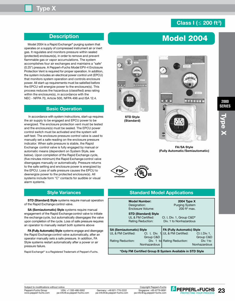
STD Style (Standard)
FA (Fully Automatic) StyleUL&FMCertified: Cl.I,Div.1, GroupC&DRatingReduction: Div.1to Nonhazardous
SA (Semiautomatic) StyleUL&FMCertified: Cl. I, Div. 1, GroupC&DRatingReduction: Div. 1 to Nonhazardous
Standard Model Applications
*Only FM Certified Group B System Available in STD Style
Model Number: 2004 Type XDesignation: PurgingSystemEnclosureVolume: 200ft3max.
STD (Standard) StyleUL&FMCertified: Cl.I,Div.1,GroupC&D*RatingReduction: Div.1toNonhazardous
Description Model2004isaRapidExchange®purgingsystemthatoperatesonasupplyofcompressedinstrumentairorinertgas.Itregulatesandmonitorspressurewithinsealed(protected)enclosure(s),inordertoremoveandpreventflammablegasorvaporaccumulations.Thesystemaccomplishesfourairexchangesandmaintainsa"safe"(0.25")pressure.APepperl+FuchsModelEPV-4EnclosureProtectionVentisrequiredforproperoperation.Inaddition,thesystemincludesanelectricalpowercontrolunit(EPCU)thatmonitorssystemoperationandcontrolsenclosurepower.Allstart-uprequirementsmustbesatisfiedbeforetheEPCUwillenergizepowertotheenclosure(s).Thisprocessreducesthehazardous(classified)arearatingwithintheenclosure(s),inaccordancewiththeNEC-NFPA70,Article500,NFPA496andISA12.4.
Basic Operation
Inaccordancewithsysteminstructions,start-uprequirestheairsupplytobeengagedandEPCUpowertobeenergized.Theenclosureprotectionventmustbetestedandtheenclosure(s)mustbesealed.TheEPCUpowercontrolswitchmustbeactivatedandthesystemwillself-test.Theenclosurepressurecontrolvalveisusedtomanuallysetasafereadingontheenclosurepressureindicator.Whensafepressureisstable,theRapidExchangecontrolvalveisfullyengagedbymanualorautomaticmeans(dependentonSystemStyle,seebelow).UponcompletionoftheRapidExchangecycle,(fiveminutesminimum)theRapidExchangecontrolvalvedisengagesmanuallyorautomatically.PressurereturnstothesafesettingandenclosurepowerisenergizedbytheEPCU.LossofsafepressurecausestheEPCUtodeenergizepowertotheprotectedenclosure(s).Allsystemsincludeform"C"contactsforaudibleorvisualalarmsystems.
Style Variances
STD (Standard) StylesystemsrequiremanualoperationoftheRapidExchangecontrolvalve.
SA (Semiautomatic)StylesystemsrequiremanualengagementoftheRapidExchangecontrolvalvetoinitiatetheexchangecycle,butautomaticallydisengagesthevalveuponcompletionofthecycle.Lossofsafepressurerequiresanoperatortomanuallyrestartbothsystemsabove
FA (Fully Automatic)StylesystemsengageanddisengagetheRapidExchangecontrolvalveautomatically,afteranoperatormanuallysetsasafepressure.Inaddition,FAStylesystemsrestartautomaticallyafterapowerorairpressurefailure.
RapidExchange®isaRegisteredTrademarkofPepperl+Fuchs.
FA/SA Style (Fully Automatic/Semiautomatic)

Type X
2000SERIES
24
Type X
Material Specifications
FilterRegulatorBody: Zincw/EnamelFinishRegulatorHandle&Bowl: PolycarbonateEnclosurePressureGauge: Alum.w/EnamelFinishRapidExchangeGauge: PolyCase&BrassTubeRapidExchangeSolenoid: Brassw/EnamelFinishTubeFittings&Valves: 316SSForgedBodyTubing: 316SS1/4"&3/8".035WeldedSystemNameplates: SilkscreenedLexan®&SSFastenerHardware: Alum.&StainlessSteelMountingPlate: 31614Ga#3BrushSSEPCUEnclosureBody: BeadBlastCastAlum.Conduit&Fittings(SA&FA): GalvanizedSteelEnclosureWarningNameplate: SilkscreenedSSLexan®isaregisteredtrademarkoftheGeneralElectricCorporation
System Specifications
SystemDimensions: Seepage26ShippingWeight: STD-49lb/SA&FA-51lbTemp.Range: -20°Fto+120°FSupplyPressureRange: 80-120psimax.Capacity&Filtration: 3.8oz@40MicronsSupplyRequirements: CleanairorinertgasSafePress.Setpoint: 0.25"@SafePress.SafePress.FlowRate: *0.1-3.5SCFHExchangePressure: 3"-5"ExchangeFlowRate: **30SCFM/1800SCFHExchangeTime: 1Minute/7.5ft3
SystemSupplyPort: 1/2"FPTEnclosureSupplyFitting: 1/2"TubeFittingEnclosureReferenceFitting: 1/4"TubeFittingEPCUConduitPortSize: 1/2"FPTEPCUPowerRequirements: 120VAC60Hz1Ø(European220voltageonly) 240VAC50Hz1Ø(Allvoltageratingsarefactoryset)EPCUPowerConsumption: 500mAPowerRelayContacts: 20A@240VAC 20A@28VDC ***[email protected]: 20A@240VAC [email protected]: 15A@240VAC 10A@28VDC
* Enclosureintegritydeterminesactualflowrate
** Withregulatorsetto80psimin.duringexchange
EPCU Description
ThePepperl+Fuchs2000SeriesEPCUisafactoryprogrammed,fieldadjustable,microprocessorcontrolledunitfeaturingfullstatusindication,redundantgatearraylogicandelectromechanicalrelays.TheEPCUisconstructedfromfourmajoritems:(1)apowermodule,(2)apressureswitchmodule,(3)alogicmoduleand(4)apowermodeselectorswitch.Thesectionsarelinkedwithpolarizedcable,andtheboardsarestackedintheEPCUenclosureonstandoffs.
Basic EPCU Operation
Whenpoweris"off",theEPCUisatrest,alarmandpowerrelaysaredeenergized,andtheLEDdisplayisoff.Whenpowerisswitched"on",theEPCUperformsaself-testofLEDdisplayandlogicfunctions.Theunitwillthenstart-up.ClassIunitsmustdetecta0.25"pressuretoenergizethealarmrelayandbeginanexchangecycle.Whenthecyclestops,thepowerrelayswillenergize.Lossofsafepressureoneitherunitcausesalarmandpowerrelaystodeenergize(seepowercontroloptionsformoreinformationregardingEPCUoperation).
RapidExchange®
SolenoidValve
FilterRegulator
System SupplyInlet
Enclosure SupplyOutlet
MountingPlate
VenturiOrifice(notvisible)
STD Style SA & FA Style (with Rapid Exchange® Solenoid Valve)
EnclosurePressureGauge
EnclosureReference Inlet
EnclosurePressureControlValve
RESVConduit
EPCUPressureReferenceTubing
FlameArrestorFitting
Electrical Wiring Diagram
Simplified EPCU Redundant Logic Diagram
PER
GAL
CLK
FAIL
PR
C
(2)
SPCR
µPSPS
(1)
(3)
EPR
EPR
SPS - SAFE PRESSURE SWITChGAL - GATE ARRAy LOGICµP - MICROPROCESSORPER - POWER ENABLED RELAySPCR - SAFE PRESSURE CONFIRMATION RELAyEPR - ENCLOSURE POWER RELAy
OPERATION
Signal(1)fromSPSissenttoµP,GALandSPCRcoil.Duringstart-up,GALverifiesallµPfunctions.GAL&µPmustreceiveuninterruptedsignalfromSPStopreventlogicresetting.AfterGALverifiesallstart-upprocedures,itsends"powerenabled"signal(2)toPERcoil.Then,µPsends"powerrequest"signal(3)throughtheSPCRandPERcontactstoEPRcoils.
CONNECTION POINTS SHOWN ABOVE IN BOLD TEXT ON SYSTEM DIAGRAM
Remote AlarmRelay Terminals
12345678910
NO Com NC
OutInIn Out
Enclosure Power Supply
Terminals
IsolatedEnclosure
PowerRelays
IsolatedAlarmRelayField Wired
Power ModuleTerminals 20A
FUSES
EPCU PowerSupply Terminals
120VAC240VAC(OptionalVoltage)
NeuNeu
HotHot
GndGnd
Type X
2000SERIES
25
Type X
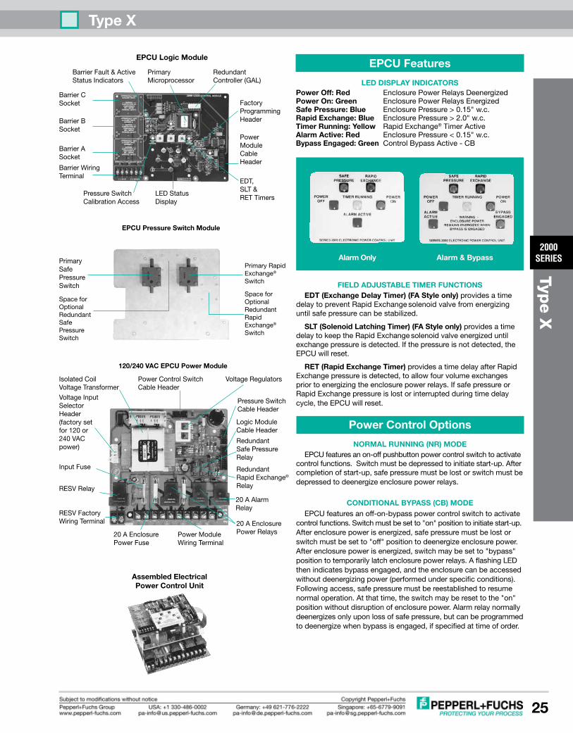
EPCU Features
LED DISPLAy INDICATORSPower Off:Red EnclosurePowerRelaysDeenergizedPower On: Green EnclosurePowerRelaysEnergizedSafe Pressure: Blue EnclosurePressure>0.15"w.c.Rapid Exchange:Blue EnclosurePressure>2.0"w.c.Timer Running:yellow RapidExchange®TimerActiveAlarm Active:Red EnclosurePressure<0.15"w.c.Bypass Engaged: Green ControlBypassActive-CB
FIELD ADJUSTABLE TIMER FUNCTIONS EDT (Exchange Delay Timer) (FA Style only)providesatimedelaytopreventRapidExchangesolenoidvalvefromenergizinguntilsafepressurecanbestabilized.
SLT (Solenoid Latching Timer) (FA Style only) providesatimedelaytokeeptheRapidExchangesolenoidvalveenergizeduntilexchangepressureisdetected.Ifthepressureisnotdetected,theEPCUwillreset.
RET (Rapid Exchange Timer)providesatimedelayafterRapidExchangepressureisdetected,toallowfourvolumeexchangespriortoenergizingtheenclosurepowerrelays.IfsafepressureorRapidExchangepressureislostorinterruptedduringtimedelaycycle,theEPCUwillreset.
Power Control Options
NORMAL RUNNING (NR) MODE EPCUfeaturesanon-offpushbuttonpowercontrolswitchtoactivatecontrolfunctions.Switchmustbedepressedtoinitiatestart-up.Aftercompletionofstart-up,safepressuremustbelostorswitchmustbedepressedtodeenergizeenclosurepowerrelays.
CONDITIONAL ByPASS (CB) MODE EPCUfeaturesanoff-on-bypasspowercontrolswitchtoactivatecontrolfunctions.Switchmustbesetto"on"positiontoinitiatestart-up.Afterenclosurepowerisenergized,safepressuremustbelostorswitchmustbesetto"off"positiontodeenergizeenclosurepower.Afterenclosurepowerisenergized,switchmaybesetto"bypass"positiontotemporarilylatchenclosurepowerrelays.AflashingLEDthenindicatesbypassengaged,andtheenclosurecanbeaccessedwithoutdeenergizingpower(performedunderspecificconditions).Followingaccess,safepressuremustbereestablishedtoresumenormaloperation.Atthattime,theswitchmayberesettothe"on"positionwithoutdisruptionofenclosurepower.Alarmrelaynormallydeenergizesonlyuponlossofsafepressure,butcanbeprogrammedtodeenergizewhenbypassisengaged,ifspecifiedattimeoforder.
PrimaryRapidExchange®Switch
SpaceforOptionalRedundantRapidExchange®Switch
SpaceforOptionalRedundantSafePressureSwitch
PowerModuleWiringTerminal
20AEnclosurePowerFuse
VoltageInputSelectorHeader(factorysetfor120or240VACpower)
RESVFactoryWiringTerminal
PressureSwitchCableHeader
LogicModuleCableHeader
RedundantSafePressureRelay
20AEnclosurePowerRelays
20AAlarmRelay
VoltageRegulatorsPowerControlSwitchCableHeader
IsolatedCoilVoltageTransformer
120/240 VAC EPCU Power Module
EPCU Pressure Switch Module
PrimarySafePressureSwitch
InputFuse
RESVRelay
RedundantRapidExchange®Relay
Alarm Only Alarm & Bypass
BarrierFault&ActiveStatusIndicators
PrimaryMicroprocessor
FactoryProgrammingHeader
LEDStatusDisplay
PressureSwitchCalibrationAccess
BarrierASocket
BarrierBSocket
BarrierCSocket
BarrierWiringTerminal
RedundantController(GAL)
PowerModuleCableHeader
EDT,SLT&RETTimers
EPCU Logic Module
Assembled Electrical Power Control Unit

Type X
2000SERIES
26
Type X
CONNECTION FITTINGS
NC-8 1/2"NinetyConnectorSC-8 1/2"StraightConnectorEFC-4 1/4"FlushConnectorEFC-8 1/2"FlushConnectorEBC-8 1/2"BulkheadConnectorEPC-14 1-1/2"PipeConnector
ADDITIONAL ITEMS
SMK-2,-3or-10 SystemMountingKitRAH RemoteAlarmHornRAB-1 Div.1RemoteAlarmBeacon
LCK LFittingConduitKitTCK TFittingConduitKitSRM-4000 SwitchResistorModuleNJ... P+FNamurSensor
INSTALLATION & OPERATION MANUAL
129-0213 Inst.&OperationManualENCLOSURE PROTECTION VENTS
ONE VENT REQUIRED WITh EACh SySTEM
EPV-4-SA-00 Straightw/SparkArrestorEPV-4-SA-90 RtAnglew/SparkArrestor
WARNING NAMEPLATES
EWN-1 ClassIEnclosureWarningETW EnclosureTemperatureWarning
FACTORy INSTALLED ACCESSORIES
IS1 ChannelABarrierIS2* ChannelBBarrierIS3* ChannelCBarrierRP1 RedundantSafePressureSwitchRP2 RedundantRapidExchangeSwitchL PowerSwitchKeyLockAssembly
*Requirescustomprogramminginformation
Dimensionsininches.Mountingdimensionsavailableuponrequest.FM&PMpanelcutoutdimensions:25hx14.50wHeight&widthdimensionsreflectmountingplatemeasurements.Depthdimensionreflectsoverallmeasurementofsystem,includingcomponents.
OverallSystem
Dimensions
FM or PM -flatpanel
26
15.50
11.50/15.75
Lh -lefthand
24
13.50
11.75/15.25
STD / SA & FA
height
Width
Depth
Rh -righthand
24
13.50
11.75/15.25
BM -bottommount
14
24
11.75/15.25
WM-wallmount
24
13.50
12.50/16.50
TM -topmount
14
24
11.75/15.25
SupplyInletFittingSC-6orNC-8
1/2"SupplyTubing
MountingKitSMK-3
EnclosureProtectionVentEPV-4-SA...
1/4"TubingReference
EnclosureSupplyFittingEBC-8
EnclosureReferenceFittingEFC-4
System Accessories Diagram
PressurizedProtectedEnclosure
WarningNameplateEWN-1
(IncludedwithPanel)
Model Number Designations
2004 - STD - CI - NR - Lh - ##
Series Model NumberSystem Style STD - Standard SA - Semiautomatic FA -FullyAutomaticArea Classification CI -ClassI,GroupC&DArea IB -ClassI,GroupBArea(STDOnly)Power Control Mode NR -NormalRunning CB -ConditionalBypassMounting Configuration Lh -lefthand leftsideofenclosure Rh -righthand rightsideofenclosure TM -topmount topofenclosure BM -bottommount bottomofenclosure WM -wallmount wallsurface FM* -framemount externalframeorrack PM* -panelmount enclosuresurfacecutout* FM & PM configurations feature flush mount EPCU. Flush mount EPCU is not suitable for Group B Area.## - See Accessories Page 132 for additional factory installed accessories
Model 2004 System Accessories (See accessories page for complete details)
ONE (1) ENCLOSURE WARNING NAMEPLATE & ONE (1) INSTALLATION & OPERATION MANUAL ARE PROVIDED WITh EACh SySTEM
BARRIER PROGRAMMING OPTIONS
Barrier A Function - when switch opens Disablesstart-upcycleDeenergizesenclosurepowerandalarmrelayFunctionsparalleltosafepressureswitchBarrier B Function - when switch opensNotprogrammed-customapplicationsonlyBarrier C Function - when switch closesEnergizesRESVrelay-customapplicationsonly
OPTIONAL INTRINSIC SAFETy BARRIERSDESCRIPTION & OPERATION
TheEPCULogicModulecanaccommodateuptothreeintrinsicsafetybarrierstointeractwithremotedevicesandaffectoperationoftheEPCU.Thebarriersareinstalledandprogrammedbythefactoryattimeoforder,andtheyaredesignedtofunctioneitherinconjunctionwithacustomerfurnishedswitchandaPepperl+Fuchsfurnishedresistornetworkcable,oraPepperl+Fuchsfurnishedproximitydetector.Eachbarrierdevelopsalowpowersignaltocreateatwo-wireclosed-loopcircuit.OperationalstatusofeachbarrierisindicatedbyagreenLEDtoshowactive(closedswitch)status,andbyaredLEDtoshowfaulted(linebreakage)cablestatus.Allbarrierscanbereprogrammedtoduplicateotherbarrierfunctionsasrequired,uponspecificrequest.

Type X
2000SERIES
27
Type X
Model 2005
Class I ( ≤ 450 ft3)
STD Style (Standard)
FA (Fully Automatic) StyleUL&FMCertified: Cl.I,Div.1, GroupC&DRatingReduction: Div.1to Nonhazardous
SA (Semiautomatic) StyleUL&FMCertified: Cl.I,Div.1, GroupC&DRatingReduction: Div.1to Nonhazardous
Standard Model Applications
*Only FM Certified Group B System Available in STD Style
Model Number: 2005 Type XDesignation: PurgingSystemEnclosureVolume: 450ft3max.
STD (Standard) StyleUL&FMCertified: Cl.I,Div.1,GroupC&D*RatingReduction: Div.1toNonhazardous
Description Model2005isaRapidExchange®purgingsystemthatoperatesonasupplyofcompressedinstrumentairorinertgas.Itregulatesandmonitorspressurewithinsealed(protected)enclosure(s),inordertoremoveandpreventflammablegasorvaporaccumulations.Thesystemaccomplishesfourairexchangesandmaintainsa"safe"(0.25")pressure.APepperl+FuchsModelEPV-5EnclosureProtectionVentisrequiredforproperoperation.Inaddition,thesystemincludesanelectricalpowercontrolunit(EPCU)thatmonitorssystemoperationandcontrolsenclosurepower.Allstart-uprequirementsmustbesatisfiedbeforetheEPCUwillenergizepowertotheenclosure(s).Thisprocessreducesthehazardous(classified)arearatingwithintheenclosure(s),inaccordancewiththeNEC-NFPA70,Article500,NFPA496andISA12.4.
Basic Operation
Inaccordancewithsysteminstructions,start-uprequirestheairsupplytobeengagedandEPCUpowertobeenergized.Theenclosureprotectionventmustbetestedandtheenclosure(s)mustbesealed.TheEPCUpowercontrolswitchmustbeactivatedandthesystemwillself-test.Theenclosurepressurecontrolvalveisusedtomanuallysetasafereadingontheenclosurepressureindicator.Whensafepressureisstable,theRapidExchangecontrolvalveisfullyengagedbymanualorautomaticmeans(dependentonSystemStyle,seebelow).UponcompletionoftheRapidExchangecycle,(fiveminutesminimum)theRapidExchangecontrolvalvedisengagesmanuallyorautomatically.PressurereturnstothesafesettingandenclosurepowerisenergizedbytheEPCU.LossofsafepressurecausestheEPCUtodeenergizepowertotheprotectedenclosure(s).Allsystemsincludeform"C"contactsforaudibleorvisualalarmsystems.
Style Variances
STD (Standard) StylesystemsrequiremanualoperationoftheRapidExchangecontrolvalve.
SA (Semiautomatic)StylesystemsrequiremanualengagementoftheRapidExchangecontrolvalvetoinitiatetheexchangecycle,butautomaticallydisengagesthevalveuponcompletionofthecycle.Lossofsafepressurerequiresanoperatortomanuallyrestartbothsystemsabove
FA (Fully Automatic)StylesystemsengageanddisengagetheRapidExchangecontrolvalveautomatically,afteranoperatormanuallysetsasafepressure.Inaddition,FAStylesystemsrestartautomaticallyafterapowerorairpressurefailure.
RapidExchange®isaRegisteredTrademarkofPepperl+Fuchs,Inc.
FA/SA Style (Fully Automatic/Semiautomatic)
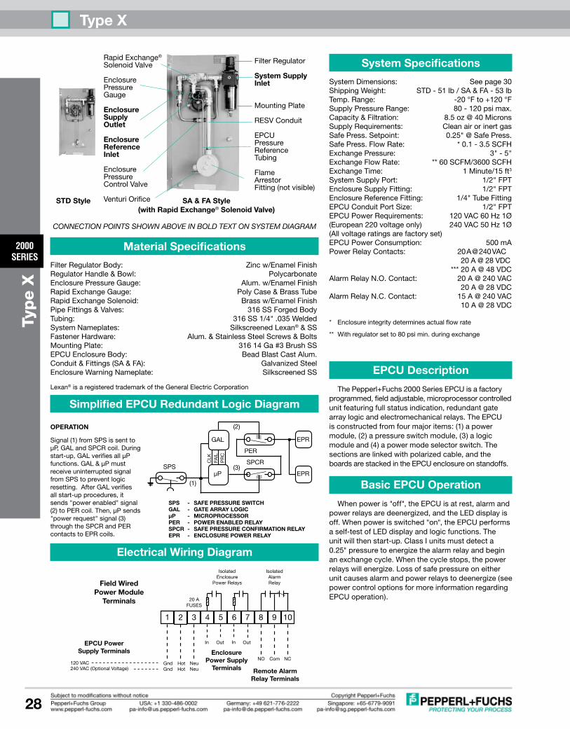
Type X
2000SERIES
28
Type X
RapidExchange®
SolenoidValve
EnclosurePressureGauge
EnclosureSupply Outlet
EnclosureReference Inlet
EnclosurePressureControlValve
VenturiOrifice
Material Specifications
FilterRegulatorBody: Zincw/EnamelFinishRegulatorHandle&Bowl: PolycarbonateEnclosurePressureGauge: Alum.w/EnamelFinishRapidExchangeGauge: PolyCase&BrassTubeRapidExchangeSolenoid: Brassw/EnamelFinishPipeFittings&Valves: 316SSForgedBodyTubing: 316SS1/4".035WeldedSystemNameplates: SilkscreenedLexan®&SSFastenerHardware: Alum.&StainlessSteelScrews&BoltsMountingPlate: 31614Ga#3BrushSSEPCUEnclosureBody: BeadBlastCastAlum.Conduit&Fittings(SA&FA): GalvanizedSteelEnclosureWarningNameplate: SilkscreenedSSLexan®isaregisteredtrademarkoftheGeneralElectricCorporation
System Specifications
SystemDimensions: Seepage30ShippingWeight: STD-51lb/SA&FA-53lbTemp.Range: -20°Fto+120°FSupplyPressureRange: 80-120psimax.Capacity&Filtration: 8.5oz@40MicronsSupplyRequirements: CleanairorinertgasSafePress.Setpoint: 0.25"@SafePress.SafePress.FlowRate: *0.1-3.5SCFHExchangePressure: 3"-5"ExchangeFlowRate: **60SCFM/3600SCFHExchangeTime: 1Minute/15ft3
SystemSupplyPort: 1/2"FPTEnclosureSupplyFitting: 1/2"FPTEnclosureReferenceFitting: 1/4"TubeFittingEPCUConduitPortSize: 1/2"FPTEPCUPowerRequirements: 120VAC60Hz1Ø(European220voltageonly) 240VAC50Hz1Ø(Allvoltageratingsarefactoryset)EPCUPowerConsumption: 500mAPowerRelayContacts: 20A@240VAC 20A@28VDC ***[email protected]: 20A@240VAC [email protected]: 15A@240VAC 10A@28VDC
* Enclosureintegritydeterminesactualflowrate
** Withregulatorsetto80psimin.duringexchange
EPCU Description
ThePepperl+Fuchs2000SeriesEPCUisafactoryprogrammed,fieldadjustable,microprocessorcontrolledunitfeaturingfullstatusindication,redundantgatearraylogicandelectromechanicalrelays.TheEPCUisconstructedfromfourmajoritems:(1)apowermodule,(2)apressureswitchmodule,(3)alogicmoduleand(4)apowermodeselectorswitch.Thesectionsarelinkedwithpolarizedcable,andtheboardsarestackedintheEPCUenclosureonstandoffs.
Basic EPCU Operation
Whenpoweris"off",theEPCUisatrest,alarmandpowerrelaysaredeenergized,andtheLEDdisplayisoff.Whenpowerisswitched"on",theEPCUperformsaself-testofLEDdisplayandlogicfunctions.Theunitwillthenstart-up.ClassIunitsmustdetecta0.25"pressuretoenergizethealarmrelayandbeginanexchangecycle.Whenthecyclestops,thepowerrelayswillenergize.Lossofsafepressureoneitherunitcausesalarmandpowerrelaystodeenergize(seepowercontroloptionsformoreinformationregardingEPCUoperation).
FilterRegulator
System SupplyInlet
MountingPlate
RESVConduit
EPCUPressureReferenceTubing
FlameArrestorFitting(notvisible)
STD Style SA & FA Style (with Rapid Exchange® Solenoid Valve)
Electrical Wiring Diagram
Simplified EPCU Redundant Logic Diagram
PER
GAL
CLK
FAIL
PR
C
(2)
SPCR
µPSPS
(1)
(3)
EPR
EPR
SPS - SAFE PRESSURE SWITChGAL - GATE ARRAy LOGICµP - MICROPROCESSORPER - POWER ENABLED RELAySPCR - SAFE PRESSURE CONFIRMATION RELAyEPR - ENCLOSURE POWER RELAy
OPERATION
Signal(1)fromSPSissenttoµP,GALandSPCRcoil.Duringstart-up,GALverifiesallµPfunctions.GAL&µPmustreceiveuninterruptedsignalfromSPStopreventlogicresetting.AfterGALverifiesallstart-upprocedures,itsends"powerenabled"signal(2)toPERcoil.Then,µPsends"powerrequest"signal(3)throughtheSPCRandPERcontactstoEPRcoils.
CONNECTION POINTS SHOWN ABOVE IN BOLD TEXT ON SYSTEM DIAGRAM
Remote AlarmRelay Terminals
12345678910
NO Com NC
OutInIn Out
Enclosure Power Supply
Terminals
IsolatedEnclosure
PowerRelays
IsolatedAlarmRelayField Wired
Power ModuleTerminals 20A
FUSES
EPCU PowerSupply Terminals
120VAC240VAC(OptionalVoltage)
NeuNeu
HotHot
GndGnd

Type X
2000SERIES
29
Type X
EPCU Features
LED DISPLAy INDICATORSPower Off:Red EnclosurePowerRelaysDeenergizedPower On: Green EnclosurePowerRelaysEnergizedSafe Pressure: Blue EnclosurePressure>0.15"w.c.Rapid Exchange:Blue EnclosurePressure>2.0"w.c.Timer Running:yellow RapidExchange®TimerActiveAlarm Active:Red EnclosurePressure<0.15"w.c.Bypass Engaged: Green ControlBypassActive-CB
FIELD ADJUSTABLE TIMER FUNCTIONS EDT (Exchange Delay Timer) (FA Style only)providesatimedelaytopreventRapidExchangesolenoidvalvefromenergizinguntilsafepressurecanbestabilized.
SLT (Solenoid Latching Timer) (FA Style only) providesatimedelaytokeeptheRapidExchangesolenoidvalveenergizeduntilexchangepressureisdetected.Ifthepressureisnotdetected,theEPCUwillreset.
RET (Rapid Exchange Timer)providesatimedelayafterRapidExchangepressureisdetected,toallowfourvolumeexchangespriortoenergizingtheenclosurepowerrelays.IfsafepressureorRapidExchangepressureislostorinterruptedduringtimedelaycycle,theEPCUwillreset.
Power Control Options
NORMAL RUNNING (NR) MODE EPCUfeaturesanon-offpushbuttonpowercontrolswitchtoactivatecontrolfunctions.Switchmustbedepressedtoinitiatestart-up.Aftercompletionofstart-up,safepressuremustbelostorswitchmustbedepressedtodeenergizeenclosurepowerrelays.
CONDITIONAL ByPASS (CB) MODE EPCUfeaturesanoff-on-bypasspowercontrolswitchtoactivatecontrolfunctions.Switchmustbesetto"on"positiontoinitiatestart-up.Afterenclosurepowerisenergized,safepressuremustbelostorswitchmustbesetto"off"positiontodeenergizeenclosurepower.Afterenclosurepowerisenergized,switchmaybesetto"bypass"positiontotemporarilylatchenclosurepowerrelays.AflashingLEDthenindicatesbypassengaged,andtheenclosurecanbeaccessedwithoutdeenergizingpower(performedunderspecificconditions).Followingaccess,safepressuremustbereestablishedtoresumenormaloperation.Atthattime,theswitchmayberesettothe"on"positionwithoutdisruptionofenclosurepower.Alarmrelaynormallydeenergizesonlyuponlossofsafepressure,butcanbeprogrammedtodeenergizewhenbypassisengaged,ifspecifiedattimeoforder.
PrimaryRapidExchange®Switch
SpaceforOptionalRedundantRapidExchange®Switch
SpaceforOptionalRedundantSafePressureSwitch
PowerModuleWiringTerminal
20AEnclosurePowerFuse
VoltageInputSelectorHeader(factorysetfor120or240VACpower)
RESVFactoryWiringTerminal
VoltageRegulatorsPowerControlSwitchCableHeader
IsolatedCoilVoltageTransformer
120/240 VAC EPCU Power Module
EPCU Pressure Switch Module
PrimarySafePressureSwitch
InputFuse
RESVRelay
PressureSwitchCableHeader
LogicModuleCableHeader
RedundantSafePressureRelay
20AEnclosurePowerRelays
20AAlarmRelay
RedundantRapidExchange®Relay
Alarm Only Alarm & Bypass
BarrierFault&ActiveStatusIndicators
PrimaryMicroprocessor
FactoryProgrammingHeader
LEDStatusDisplay
PressureSwitchCalibrationAccess
BarrierASocket
BarrierBSocket
BarrierCSocket
BarrierWiringTerminal
RedundantController(GAL)
PowerModuleCableHeader
EDT,SLT&RETTimers
EPCU Logic Module
Assembled Electrical Power Control Unit

Type X
2000SERIES
30
Type X
Dimensionsininches.Mountingdimensionsavailableuponrequest.FM&PMpanelcutoutdimensions:26hx14.50wHeight&widthdimensionsreflectmountingplatemeasurements.Depthdimensionreflectsoverallmeasurementofsystem,includingcomponents.
OverallSystem
Dimensions
FM or PM -flatpanel
27
15.50
11.25/15.75
Lh -lefthand
25
13.50
10.75/15.25
STD / SA & FA
height
Width
Depth
Rh -righthand
25
13.50
10.75/15.25
BM -bottommount
14
25
10.75/15.25
WM-wallmount
25
13.50
12.50/16.50
TM -topmount
14
25
10.75/15.25
CONNECTION FITTINGS
EFC-4 1/4"FlushConnectorEPC-10 1/2"PipeConnector
ADDITIONAL ITEMS
SMK-2,-3or-10 SystemMountingKitRAH RemoteAlarmHornRAB-1 Div.1RemoteAlarmBeaconLCK LFittingConduitKitTCK TFittingConduitKitSRM-4000 SwitchResistorModuleNJ... P+FNamurSensor
INSTALLATION & OPERATION MANUAL
129-0214 Inst.&OperationManualENCLOSURE PROTECTION VENTSONE VENT REQUIRED WITh EACh SySTEM
EPV-5-SA-00 Straightw/SparkArrestorEPV-5-SA-90 RtAnglew/SparkArrestor
WARNING NAMEPLATES
EWN-1 ClassIEnclosureWarningETW EnclosureTemperatureWarning
FACTORy INSTALLED ACCESSORIES
IS1 ChannelABarrierIS2* ChannelBBarrierIS3* ChannelCBarrierRP1 RedundantSafePressureSwitchRP2 RedundantRapidExchangeSwitchL PowerSwitchKeyLockAssembly
*Requirescustomprogramminginformation
SupplyInletFitting
1/2"SupplyPipe
MountingKitSMK-3
EnclosureProtectionVentEPV-5-SA...
1/4"TubingReference
EnclosureSupplyFittingEPC-10
EnclosureReferenceFittingEFC-4
System Accessories Diagram
PressurizedProtectedEnclosure
WarningNameplateEWN-1
(IncludedwithPanel)
Model Number Designations
2005 - STD - CI - NR - Lh - ##
Series Model NumberSystem Style STD - Standard SA - Semiautomatic FA -FullyAutomaticArea Classification CI -ClassI,GroupC&DArea IB -ClassI,GroupBArea(STDOnly)Power Control Mode NR -NormalRunning CB -ConditionalBypassMounting Configuration Lh -lefthand leftsideofenclosure Rh -righthand rightsideofenclosure TM -topmount topofenclosure BM -bottommount bottomofenclosure WM -wallmount wallsurface FM* -framemount externalframeorrack PM* -panelmount enclosuresurfacecutout* FM & PM configurations feature flush mount EPCU. Flush mount EPCU is not suitable for Group B Area.## - See Accessories Page 132 for additional factory installed accessories
Model 2005 System Accessories (See accessories page for complete details)
ONE (1) ENCLOSURE WARNING NAMEPLATE & ONE (1) INSTALLATION & OPERATION MANUAL ARE PROVIDED WITh EACh SySTEM
BARRIER PROGRAMMING OPTIONS
Barrier A Function - when switch opens Disablesstart-upcycleDeenergizesenclosurepowerandalarmrelayFunctionsparalleltosafepressureswitchBarrier B Function - when switch opensNotprogrammed-customapplicationsonlyBarrier C Function - when switch closesEnergizesRESVrelay-customapplicationsonly
OPTIONAL INTRINSIC SAFETy BARRIERSDESCRIPTION & OPERATION
TheEPCULogicModulecanaccommodateuptothreeintrinsicsafetybarrierstointeractwithremotedevicesandaffectoperationoftheEPCU.Thebarriersareinstalledandprogrammedbythefactoryattimeoforder,andtheyaredesignedtofunctioneitherinconjunctionwithacustomerfurnishedswitchandaPepperl+Fuchsfurnishedresistornetworkcable,oraPepperl+Fuchsfurnishedproximitydetector.Eachbarrierdevelopsalowpowersignaltocreateatwo-wireclosed-loopcircuit.OperationalstatusofeachbarrierisindicatedbyagreenLEDtoshowactive(closedswitch)status,andbyaredLEDtoshowfaulted(linebreakage)cablestatus.Allbarrierscanbereprogrammedtoduplicateotherbarrierfunctionsasrequired,uponspecificrequest.

Type X
2000SERIES
31
Type X
Series Model Number 2001A, 2001B, 2001C, 2002, 2003, 2004, 2005System Style STD - Standard SA - Semiautomatic FA -FullyAutomaticArea Classification CI -ClassI,GroupC&DArea CII -ClassII,GroupE,F&GArea IB -ClassI,GroupBArea(STDOnly)Power Control Mode NR -NormalRunning CB -ConditionalBypassMounting Configuration Lh -Lefthand(leftsideofenclosure) Rh -Righthand(rightsideofenclosure) TM -Topmount(topofenclosure) BM -Bottommount(bottomofenclosure) WM -Wallmount(wallsurface) FM* -Framemount(externalframeorrack) PM* -Panelmount(enclosuresurfacecutout) * FM & PM configurations feature flush mount EPCU. Flush mount EPCU is not suitable for Group B Area.Cooler Indicator Gauge (seepage97) VX -VortexKey Lock Assembly (seepage113) L -KeyLockAssemblyIntrinsic Safe Barrier (seepage112) IS1 -ISBarrier,ChannelABarrier IS2 -ISBarrier,ChannelBBarrier IS3 -ISBarrier,ChannelCBarrier IS4 -ISBarrier,ChannelsAandBBarrier IS5 -ISBarrier,ChannelsBandCBarrier IS6 -ISBarrier,ChannelsAandCBarrier IS7 -ISBarrier,AllChannelsBarrierRedundant Pressure Switches (seepage113) RP1 -RedundantSafePressureSwitches RP2 -RedundantRapidExchange®PressureSwitches RP3 -BothSwitchesVoltage 24 VDC -VoltageDirectCurrents 240 VAC -VoltageAlternatingCurrents
2000 - - - - - - - - -
2000 Series — Model Number Designations and Accessories Guide
Pepperl+Fuchssuppliespurge/pressurizationsystemscustombuilttoyourspecifications.Toensuretheintegrityofyoursystem,certainaccessoryitemsmustbefactoryinstalled.
TheModelNumberandAccessoriesGuideidentifiesthosepartsthatmustbeincludedonyourpurge/pressurizationsystemorder.
Type X
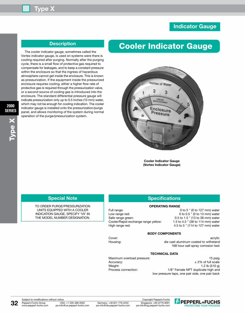
Type X
2000SERIES
32
Type X
Special Note
TOORDERPURGE/PRESSURIZATIONUNITSEqUIPPEDWITHACOOLER
INDICATIONGAUGE,SPECIFy‘VX’INTHEMODELNUMBERDESIGNATION.
Description
Thecoolerindicatorgauge,sometimescalledtheVortexindicatorgauge,isusedonsystemswerethereiscoolingrequiredafterpurging.Normallyafterthepurgingcycle,thereisasmallflowofprotectivegasrequiredtocompensateforleakages,andtokeepaconstantpressurewithintheenclosuresothattheingressofhazardousatmospherecannotgetinsidetheenclosure.Thisisknownaspressurization.Iftheequipmentinsidethepressurizedenclosurerequirescooling,eitherahigherflowrateofprotectivegasisrequiredthroughthepressurizationvalve,orasecondsourceofcoolinggasisintroducedintotheenclosure.Thestandarddifferentialpressuregaugewillindicatepressurizationonlyupto0.5inches(13mm)water,whichmaynotbeenoughforcoolingindication.Thecoolerindicatorgaugeisinstalledontothepressurization/purgepanel,andallowsmonitoringofthesystemduringnormaloperationofthepurge/pressurizationsystem.
Cooler Indicator Gauge
Specifications
OPERATING RANGEFullrange: 0to5"(0to127mm)waterLowrangered: 0to0.5"(0to13mm)waterSaferangegreen: 0.5to1.5"(13to38mm)waterCooler/Rapidexchangerangeyellow: 1.5to4.5"(38to114mm)waterHighrangered: 4.5to5"(114to127mm)water
BODy COMPONENTSCover: acrylicHousing: diecastaluminumcoatedtowithstand 168hoursaltspraycorrosiontest
TEChNICAL DATAMaximumoverloadpressure: 15psigAccuracy: ±2%offullscaleWeight: 1.2lb(510g)Processconnection: 1/8”FemaleNPTduplicatehighand lowpressuretaps,onepairside,onepairback
Indicator Gauge
Cooler Indicator Gauge(Vortex Indicator Gauge)

5 1
8
4
2
6
7
3
Subject to modifications • © 2010 PEPPERL+FUCHS, INC. • Printed in USA • Part No. TDOCT-B062_USA
www.pepperl-fuchs.com
PROCESS AUTOMATION – PROTECTINg yOUR PROCESS
Worldwide/german Headquarters Pepperl+Fuchs GmbH Mannheim · GermanyTel. +49 621 776 2222
E-Mail: [email protected]
1
Asia Pacific HeadquartersPepperl+Fuchs PTE Ltd.
SingaporeCompany Registration No. 199003130E
Tel. +65 6779 9091E-Mail: [email protected]
2
Central/Western Europe & Africa HeadquartersPepperl+Fuchs N.V.
Schoten/Antwerp · BelgiumTel. +32 3 6442500
E-Mail: [email protected]
3
Middle East HeadquartersPepperl+Fuchs M.E (FZE)
Dubai · UAETel. +971 4 883 8378
E-Mail: [email protected]
4
North/Central America Headquarters Pepperl+Fuchs Inc.
Twinsburg · Ohio · USATel. +1 330 486 0002
E-Mail: [email protected]
5
Northern Europe HeadquartersPepperl+Fuchs GB Ltd.
Oldham · EnglandTel. +44 161 6336431
E-Mail: [email protected]
6
Southern/Eastern Europe HeadquartersPepperl+Fuchs Elcon srl
Sulbiate · ItalyTel. +39 039 62921
E-Mail: [email protected]
7
Southern America HeadquartersPepperl+Fuchs Ltda.
São Bernado do Campo · SP · BrazilTel. +55 11 4341 8448
E-Mail: [email protected]
8
For over a half century, Pepperl+Fuchs has provided new concepts for the world of process automation. Our company sets standards in quality and innovative technology. We develop, produce and distribute electronic interface modules, Human-Machine Interfaces and hazardous location protection equipment on a global scale, meeting the most demanding needs of industry. Resulting from our world-wide presence and our high flexibility in production and customer service, we are able to offer complete individual solutions – wherever and whenever you need us. We are the recognized experts in our technologies – Pepperl+Fuchs has earned a strong reputation by supplying the world’s largest process industry companies with the broadest line of proven components for a diverse range of applications.