pump control - whiteint.com.au711242_500.pdf · installation 3 mounting connection welcome to dual...
TRANSCRIPT

Dual Pump Controller Installation and Operating Instructions
PUMP CONTROL
OFF
ON
Dual PumpController
PUMP 1 PUMP 2
AUTO
OFF
AUTO
OFF
MAN MANMUTE/RESET
PUMP ONPUMP ONFAULT FAULT
LEVELALARM
POWERON
DANGER - HIGH VOLTAGE DO NOT REMOVE COVER. AUTHORIZED PERSONS ONLY
Steady - OverloadFlash - Prime Loss
Steady - OverloadFlash - Prime Loss
Press and holdfor 3 secs to reset
Steady - High LevelFlash - Low Level
DOC: DPC 30010 REVISED: 220210

INSTALLATION 3MountingConnection
WELCOME TO DUAL PUMP CONTROL
Your Dual Pump Controller reflects the superior quality and attention to detail
in design, engineering and manufacturing that has distinguished MATelec
Products for decades. The controller incorporates the very latest in micro-
processor technology, ensuring you, the owner/operator, of many years of
functional, reliable and ‘user friendly’ operation.
Please read this manual prior to installation and operation of the controller.
GETTING STARTED 4OperationsFeatures
WARNING: All electrical connections must be carried out by a suitably qualified and registered electrician.
• Prior to Installation, ensure power supply is isolated.
• Power supply must be Circuit Breaker Protected. (Qualified Electrician to determine appropriate amp
rating.)
• Electrical connection to the panel must be carried out in accordance with ‘Connection Instructions’,
see page 3.
• Additions or modifications to the control panel are not permitted and will void warranty.
• The controller is not intended for use by children or infirm persons without supervision.
• Repairs to the Controller must only be carried out by a suitably qualified Electrician.
2
SAFETY 2 CIRCUIT DIAGRAM 7
AT A GLANCE 8
IndicatorsPush Buttons

3
1. Controller enclosure must be mounted in a vertical position.2. Ensure mounting method does not compromise enclosure weather proof rating.3. Ensure access to main isolator is not restricted.4. Ensure cables/conduits entering the panel have mechanical protection and that the penetrations are sealed and do not compromise the weather proof rating of the enclosure.
MOUNTING
FRONT VIEW SIDE VIEW
Top
Bottom
Top
Bottom
Mounting Frame/Wall
CONNECTION
NOTE: Controller must be earthed and all electrical connections must be carried out by a suitably qualified Electrician
OFF
ON
Dual PumpController
PUMP 1 PUMP 2
AUTO
OFF
AUTO
OFF
MAN MANMUTE/RESET
PUMP ONPUMP ONFAULT FAULT
LEVELALARM
POWERON
DANGER - HIGH VOLTAGE DO NOT REMOVE COVER. AUTHORIZED PERSONS ONLY
Steady - OverloadFlash - Prime Loss
Steady - OverloadFlash - Prime Loss
Press and holdfor 3 secs to reset
Steady - High LevelFlash - Low Level
PUMP 1 PUMP 2
240VacMAINS POWER
SUPPLY
SUPPLY
HighActiv
e
Activ
e
Neut
ral INPUT SWITCHES
Level Level LevelNeut
ral
Input 2 Input 3
Earth
Activ
e
Neut
ral
240Vac 12Vdc ConnectionsNote:
Applications, connect to "Start (Input 3)" terminals only, and NO
PUM
P 1
Earth
PUM
P 2
EarthInput 4
Stop Start
PUMP 1 PUMP 2
BLUE NOT REQUIRED
STOP/LOW
LEVEL
COM
MO
N
N/O
CLO
SE O
N R
ISE
START/MEDIUM
LEVEL
COM
MO
N
N/O
CLO
SE O
N R
ISE
STANDBY/HIGHLEVEL
COM
MO
N
N/O
CLO
SE O
N R
ISE
SET THERMAL OVERLOADS TO SUIT PUMP

This controller can perform control functions for most Dual Pump pumping applications. It is more than likely that the control parameters have already been set up for your particular application however; hereunder you will find details of the set up and configuration options. There are 6 DIP switches located on the lower side of the control module, which allow s for selecting “mode” and “feature” options, as per the following table:
Operation Selection Table DIP Switch Position Function
1/2
Off/Off Mode A:
Off/On Mode B:
On/Off Mode C:
On/On Mode D:
3 Off
On
4 Off Anti-seize timer disabled
On Anti-seize timer 10 seconds every 7 days enabled
5 Off When placed in Manual mode pump remains in Manual mode
On When placed in Manual mode after 5 minutes, the pump will revert to Auto
6
Off High Level alarm Automatically resets upon open circuit of high level input. High level alarm has 15 Minute delay .
On High level alarm can only be reset Manual ly . High level alarm has 5 minute delay .
Mode A: Standard configurationStart/Stop/High level operation. When the pump start input is closed contact (triggered), the duty pump will be
Standard typical float switch configuration (Start, Stop and High Level).No low level. Standard configuration plus low level (Start, Stop, High level and Low level).
Standard configuration plus Prime Loss enabled, on Low level (Input 1)
Pressure Pumping configuration (Lead, Lag and Low pressure)
Operating pump alternates after 6 hours continuous running
Operating pump alternates each time a pump start is triggered, or after 30 minutes continuous running.
turned on. The pump will remain on until both the pump start and pump stop inputs have turned off (open circuited). Upon high level both pumps will run until the pump stop input turns off.
In addition to this, there is a maximum idle timer, which will trigger a pump start condition, if either pump has not run for 4 hours, and the stop float contacts are closed. The pump will continue to run until the stop float contacts open. Input functions are as follows:
Mode B: Standard Configuration plus Low Level Alarm As per Mode A, except it has an active Low Level input. The low level input must be closed, for pump start and pump stop inputs to function. The High level input however, will still override the low level and run both pumps. Input functions are as follows:
The basic logic on which a High or Low Level Alarm is determined, is set out in the Table A.
Input Function
Input 1 Low Level
Input 2 Pump Stop
Input 3 Pump Start
Input 4 High Level
Input Function
Input 1 Not Used
Input 2 Pump Stop
Input 3 Pump Start
Input 4 High Level
4

5
Table A
Input 1
Low Level
Input 2
Pump Stop Input 3
Pump Start
Input 4 High Level
PumpState
Alarm
Closed Open/Closed Open Open Off - Closed Open/Closed Closed Open On - Closed Open/Closed Closed Closed Both on High level (after timeout) Closed Open/Closed Open Closed Both on High level (after timeout) Open Open/Closed Open Open Off - Open Open/Closed Closed Open Off Low level Open Open/Closed Open Closed Off Low level Open Open/Closed Closed Closed Both on High level (after timeout)
Mode C: Standard Configuration plus Prime LossAs per Mode A, except Input 1 is connected to a prime loss/flow switch. If at any stage, after pump startor whilst a pump is running, the prime loss input closes, for a continuous 2 minute period, a fault is immediatelytriggered for that pump and duty alternates. Input functions are as follows:
Input Function Input 1 Prime Loss Input 2 Pump Stop Input 3 Pump Start Input 4 High Level
Mode D: Pressure Pumping ConfigurationDuty Pump: Lead PumpStandby Pump: Lag PumpInput functions are as follows:
Input FunctionInput 1 Not used Input 2 Input 3 Input 4
If there is a low level alarm , then both pumps will be locked out until the alarm is manually reset. This lockout will only be overidden upon a high level condition where both the Pump Start and HighLevel inputs are closed.
Note that after a high level is triggered, the pumps will both run until the pump Start and Stop inputs are opened.
Typical operation for Mode D
Low pressure switch (set at say 200kPa)Lag pump pressure switch (set at say 350kPa)Lead pump pressure switch (set at say 350kPa)
Pressure drops to 400kPA: Lead (for this cycle) Pump cuts in.
Pressure increases and Pump cuts out.
Cycle continues with duty (Lead and Lag) alternating between the two pumps.
If pressure drops to 350kPA, Lag Pump will cut in and remain running until Lead Pressure switchopens circuit. Then duty alternates.
No faults are logged against the Lead Pump if the Lag Pump starts.
The controller has inbuilt timers for”Delayed” Start and Stop to obviate pump chatter. Upon Input 1contact closure, the pump will not start (delay start) for 3 seconds and will not stop (minimum run time) for 30 seconds (or 33 seconds from close of Input contacts). This “run on” occurs even if Lead Pressure switch opens circuit during this initial period. If however run time exceeds 33 seconds, the pump will stop immediately upon “open circuit” occuring.
If the Lead Pressure Switch input closes circuit as well as the Low Pressure Switch input, both pumps will be turned on and the Low Pressure Timer will begin counting.If this condition exists for a period of 60 seconds, then both pumps are shut down and the system signals a level alarm. This would be typical of a Loss of Prime or Burst Main situation.
Pressure switches are normally Closed and Open on High pressure

6
Maximum Run and Alternation ModeWith DIP Switch 3 set to “Off” the unit will alternate as usual each time a pump start condition occurs.Additionally, the controller will automatically alternate pump duty if a pump has been running continuously for 30 minutes (maximum run timer)Setting this DIP switch to “On” will cause the controller to operate in “Circulation Mode” where duty will only alternate once the pump has run for 6 hours of accumulated time.
Anti-seize TimerWith DIP Switch 4 set to “On”, the Anti-seize timer wil automatically run the pumps for 10 seconds, every 7 days. This pump operation will completely override all inputs including the low level (if enabled). This feature will onlyrun pumps that are set in Auto. This “Pump Run”, will alternate between Pump 1 and Pump 2. A pump that hasbeen locked out due to a fault will not run.
Manual Mode TimeoutWith DIP switch 5 set to “On” the pump will only remain in Manual Mode for 5 minutes, after which time, it automatically reverts to Auto.
Audible and Visual Alarm TestBy pressing the Mute/Reset button on the keypad continuously for a period of 5 seconds, the Strobe, Siren andIndicator Lights will be powered up for inspection
Fault ResetTo reset all faults on the controller, press and hold the Mute/Reset button on the keypad continuously for a period of 3 seconds until an acknowledgement beep is heard.
Pump FaultA Pump Fault is indicated for two types of Faults. A Thermal Overload will be indicated by way of a steady Fault Indicator light. A Prime Loss fault will be indicated by way of a flashing Fault Indicator Light. Both types of faults can be reset by way of the Fault Reset button.
Level AlarmsA High Level Alarm is indicated by way of a steady Level Alarm Indicator Light.A Low Level/Low Pressure Alarm is indicated by way of a Flashing Level Alarm Light.
Auto Silencing Alarm FeatureThe audible Alarm is programmed to sound for 5 minutes continuously, unless muted and will thereafter automaticallysilence and enter “Chirp” mode. In Chirp Mode, the Audible Alarm will sound briefly (2 Seconds)every 5 minutes
High Level Alarm ResetWith DIP Switch 6 set to “Off”, the high level alarm will automatically reset once the high level input opens circuit.The controller will also use the alternate high level alarm delay. Typically used for Storm Water applications. High Level Alarm delay in this mode is 15 minutes.
Setting this DIP switch to “On”, will cause the high level alarm to remain active until the controller is reset. Thehigh level alarm will use the standard high level alarm activation delay. Typically used for Sewerage applications.High Level Alarm delay in this mode is 5 minutes.

7
MODESELECT
INPUT2INPUT14-20mA
+ -INPUT3 INPUT4 BMS/
REMOTESTROBE
- +SIREN- +
POWER12Vac
PUMP 1 PUMP 2PUMP 2FAULT
PUMP 1FAULT
KEYPAD CONNECTION PIN 1
500mA
DUAL PUMPCONTROLLERCOM-30089
240V 10A MAX
Australia
®
IMPORTANT: READ INSTALLATION AND OPERATION MANUAL BEFORE USE
TOL TOL
TOL
TOL
A1 A2 A2
98979897
A1
A
N
E
CONTACTORCOILS
PUMP 1
CON
TACTO
R 1
20amp
2 POLE
PUM
P 1ISO
LATOR
20amp
2 POLE
PUM
P 2ISO
LATOR
CON
TACTO
R 2
PUMP 2
DATAOUTPUT
2ampCONTROLCIRCUIT
BREAKER
ISOLATOR SWITCH
STROBE BUZZER
TRANSFORMER
12Vac
12Vdc
240Vac
INPUT 1SWITCH
INPUT 2SWITCH
INPUT 3SWITCH
INPUT 4SWITCH
12Vdc12Vdc
Dual PumpController
PUMP 1 PUMP 2
AUTO
OFF
AUTO
OFF
MAN MANMUTE/RESET
PUMP ONPUMP ONFAULT FAULT
LEVELALARM
POWERON
DANGER - HIGH VOLTAGE DO NOT REMOVE COVER. AUTHORIZED PERSONS ONLY
Steady - OverloadFlash - Prime Loss
Steady - OverloadFlash - Prime Loss
Press and holdfor 3 secs to reset
Steady - High LevelFlash - Low Level
MANUFACTURED BY MATelec AUSTRALIA EMAIL: [email protected] reserves the right to alter technical specifications without notice
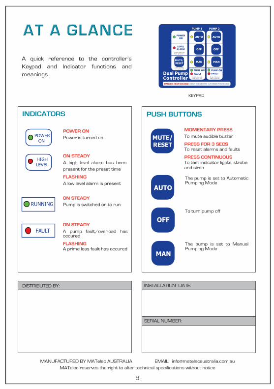
A quick reference to the controller’s Keypad and Indicator functions and meanings.
KEYPAD
INDICATORS PUSH BUTTONS
POWER ONPower is turned on
ON STEADYA high level alarm has been present for the preset time
FLASHINGA low level alarm is present
ON STEADYA pump fault/overload has occured
FLASHINGA prime loss fault has occured
The pump is set to Automatic Pumping Mode
The pump is set to Manual Pumping Mode
To turn pump off
DISTRIBUTED BY:
8
INSTALLATION DATE:
SERIAL NUMBER:
Dual PumpController
PUMP 1 PUMP 2
AUTO
OFF
AUTO
OFF
MAN MANMUTE/RESET
PUMP ONPUMP ONFAULT FAULT
LEVELALARM
POWERON
DANGER - HIGH VOLTAGE DO NOT REMOVE COVER. AUTHORIZED PERSONS ONLY
Steady - OverloadFlash - Prime Loss
Steady - OverloadFlash - Prime Loss
Press and holdfor 3 secs to reset
Steady - High LevelFlash - Low Level
MUTE/RESET
AUTO
OFF
MAN
RUNNING
FAULT
ON STEADYPump is switched on to run
MOMENTARY PRESSTo mute audible buzzer
PRESS FOR 3 SECSTo reset alarms and faults
PRESS CONTINUOUSTo test indicator lights, strobe and siren
POWERON
HIGHLEVEL