pulsed power driven experiments in the institute of … · pulsed power driven experiments . in the...
TRANSCRIPT

Pulsed Power Driven Experiments in the Institute of Shock Physics
Simon
Bland Imperial College London

Work carried out with and many thanks to:

Outline of talk
Initial (very initial) magnetically driven ramp experiments
Radiative shock wave and bow shocks in plasmas
A plasma drive for high pressure experiments
Future program
•
MACH•
Diagnostic development
•
Advanced concepts

High Pressure EOS measurements
Sample (<mm3)Diamond anvil cells are used to provide up to Mbar ‘static’
information

High Pressure EOS measurements
Sample (<mm3)
Plate impacts generate shocks to obtain EOS measurements in dynamic systems / at high pressures
Diamond anvil cells are used to provide up to Mbar ‘static’
information
Target
Velocimetry diagnostics measure shock breakout
Explosives, Gas gun, laser ablation
Flyer (v~kms-1)
P
V
HugoniotGas guns generate high precision data up to 2-3 Mbar pressure, but tend to sample along Hugoniot
Isentrope
Magnetic fields (and plasma) generated using pulsed power can drive ramp pressures•‘quasi isentropic process’
sample below
Hugoniot to high pressures • can launch very high speed flyer plates

Magnetic driven experiments pioneered at Sandia
On Z (26MA, 200ns):Isentropic pressures up to ~6MBarFlyer velocities ~10s of kms-1
Studies include EOS of Beryllium, diamond, aluminium and special nuclear materials

Imperial College MAGPIE facility
Get experience in magnetically driven isentropic compression experimentsCan also look at shocks in plasmas -
e.g. astro relevant radiative shock waves
And using plasma explore new methods of applying high pressures to targets
MegaAmpereGenerator forPlasmaImplosionExperiments
At Imperial the 1.5MA 240 ns MAGPIE generator drives HEDP experiments on a daily basis

B
Pressure on target material
‘strip line’
load configuration
I
Velocity diagnostics monitor movement of free surface
pulsed power generator
0 200 4000
50
100
150
200
Pre
ssur
e (k
bar)
Time (ns)
B
Each side of strip line sees equivalent pressure profile
(w is width of strip)
on MAGPIE ~2MA, 250ns rise time, 10mm wide strip line gives ~ 200KBar
Magnetically driven EOS experimentsHigh magnetic field can provides ramp pressure loading
Basic ICE setup:
2
2o
0
2
2wIμ
2μBP ==
wIμB 0=
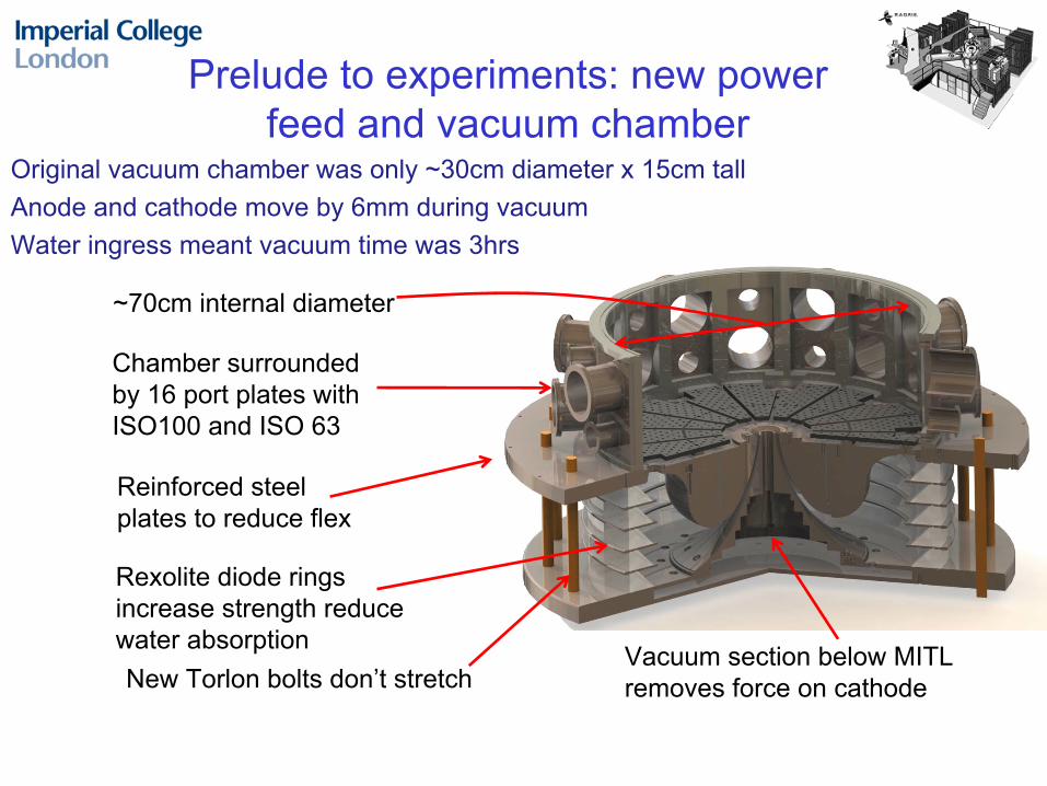
Prelude to experiments: new power feed and vacuum chamber
~70cm internal diameter
Chamber surrounded by 16 port plates with ISO100 and ISO 63
Reinforced steel plates to reduce flex
New Torlon bolts don’t stretchVacuum section below MITL removes force on cathode
Rexolite diode rings increase strength reduce water absorption
Original vacuum chamber was only ~30cm diameter x 15cm tallAnode and cathode move by 6mm during vacuumWater ingress meant vacuum time was 3hrs
Anode and cathode now move ~25umVacuum time <1hr

cathode in throat of MITL
sample area up to 60x12mm on each side
15mm width for 60 kBar peak pressure
Initial experiments: Feb 2010•
Stripline design maximises available drive pressure, and simplifies design
•
Length of electrodes 40 –
80mm•
Width of electrodes 20 –
10mm → Pressures from ~30-120kBar with 1.5MA drive

Initial experiments: Feb 2010Design and manufacturing issues:•
Will the gap breakdown?
•
How uniform is the drive?
•
Need to use a soft material and needs to be easily machined -
Copper•
Target thicknesses 1-7mm -
shocks expected after ~5mm thickness
•
How to support over large areas, polish etc
1 –
2 mm gap in striplinevoltages ~200kV
Side view of stripline
Front view of one electrode with target
area outlined
80m
m
EM simulations difficult due to large scale of electrodes c.f. gap in stripline... => electrodes designed from simple assumptions and results will serve as test for code

Initial experiments: Feb 2010Typically for shock experiments:flatness ~5um, roughness <um via. diamond machiningOverkill for initial experiments (and very expensive)
Tour de Force by Imperial College Instrumentation workshop2 part ‘glued electrode’
electrode -
target area and support
4 axis CNC mill allows fast production of blanksPrecision ground then hand polished –
mirror finish ~5um
Close up of 20mm wide copper strip line in MAGPIE
Target area (60x17mm)
Gap (2mm)
Return electrode

Initial experiments: Feb 2010
Top down view
Side view of strip line
Holder for Het-V probes
Resistive voltage probe
Stripline mounted on break away system to prevent damage to MAGPIE
Path of probing laser
½
inch armoured plate top and bottom to ‘catch’
stripline (not shown)

Initial experiments: Feb 2010Laser probing of gap in 20mm wide stripline shows little build up of plasma ☺Voltage monitored across stripline also indicates no sudden breakdowns occurring⇒ Consistent with all current
flowing through strip line(should give 20-30kBar)
Laser shadow image @200ns Laser interferogram @200ns
Only plasma present comes from join to holder –
expands
~200um into gap

Initial experiments: Feb 2010Post shot target recovery...
80x20mm electrode, with support (left) and target plate (right)
40x20mm target plate
No target plate showed any sign of spall –
consistent with isentropic compressionTarget plates did prove to be good flyer plates though, vaporising diagnostics and ricocheting off armour plates

Initial experiments: Feb 2010Unfortunately the Het-V probe indicated a laser fault...... Hence we have no EOS information yet (but only 3 shots)
Het-V system is now in repair before next shot seriesVISAR and line VISAR will be added, in addition to other diagnosticsMeanwhile, we have also examined other ways of driving shock experiments
0 100 200 300 400 500-0.2
0.0
0.2
Sig
nal (
AU
)
Time (ns)
1 5 0 2 0 0 2 5 0 3 0 0 3 5 0 4 0 0 4 5 0 5 0 0- 0 .0 1 0
- 0 .0 0 5
0 .0 0 0
0 .0 0 5
0 .0 1 0
Sig
nal (
AU
)
T im e (n s )
What we got
What we wish we had got

Pulsed power can also drive large scale, well diagnosed shocks in plasma

Pulsed power driven Radiative Shocks
Radiative shock waves occur when strong heating from shocked material affects the shock front
e.g. Supernovae and imploding ICF capsules
Usually experiments limited to sub mm scale
‘Radial foil’
z-pinch6cm diameter 6um Al foil, with 3.1mm cathode underneath
mbar gas fill above foil (He -
Xe) –
application of MA currents results in
shock launching through gas

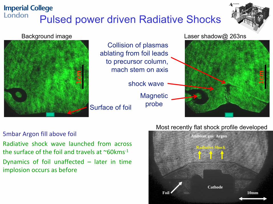
Background image Laser shadow@ 263ns
Surface of foil
Magnetic probe
shock wave1cm
Collision of plasmas ablating from foil leads
to precursor column, mach stem on axis
1cm
5mbar Argon fill above foil
Radiative
shock
wave
launched
from
across
the surface of the foil and travels at ~60kms‐1
Dynamics
of
foil
unaffected
– later
in
time
implosion occurs as before
Pulsed power driven Radiative Shocks
10mm
Ambient gas: Argon
Radiative Shock
FoilCathode
Most recently flat shock profile developed

Laser shadowgram @320ns
5mbar Argon fill above foil, 2mm stainless steel sphere and 3mm polystyrene sphere
Configuration for cylindrical radiative shock experiment
Whatever process is responsible, the large scale shock wave allows extremely well diagnosed interaction experiments.Now exploring experiments with shock waves that should interact with the targets, and experiments in convergent geometries
Pulsed power driven Radiative Shocks
InterferogramBow shock

Using plasma generated by pulsed powerImplosion Stagnation Peak emission
23m
m
At MAGPIE we pioneered understanding of the implosion of wire array z-pinches
0 20 40 60 80 1000.0
0.2
0.4
0.6
0.8
% of implosion time
Rad
ius
(mm
)Trajectory of wire array
ablation
Precursor column
1000s of tonnes/sec
The majority of the evolution of a wire array is dominated by the gradual ablation of the wires into dense, warm plasma ni
~ 1016
-1017 cm-3
Ti ~30eVvelocity ~ 150kms-1
X-ray pulse

Using plasma generated by pulsed powerImplosion Stagnation Peak emission
23m
m
At MAGPIE we pioneered understanding of the implosion of wire array z-pinches
The majority of the evolution of a wire array is dominated by the gradual ablation of the wires into dense, warm plasma ni
~ 1016
-1017 cm-3
Ti ~30eVvelocity ~ 150kms-1
Side-on
Plasma from wires Precursor
End-on

We can place targets in the flow to examine bow shocks in high Mach flows.
Experimental set up End on emission images(bottom) and simulations (top)
In experiments later this year we will make a planar flow of plasma that projects into open space –
vastly simplifying experimental set up and diagnostic access
Using plasma generated by pulsed power

Using a conical array results in ablated plasma being redirected out of the array as a high mach number plasma jet
Using a plasma jet to apply high pressures

Using a conical array results in ablated plasma being redirected out of the array as a high mach number plasma jetAblation as rocket model
Pressures gradually rising >>100 KbarCan use jet to apply high pressures
abl
2o
abl Rv.4Iμ)(I
v1
dtdm
π=∧= B
Using a plasma jet to apply high pressures
200 250 300 350 400 450 5000
20
40
60
80
100
120
Pre
ssur
e (k
bar)
T im e (ns)
Pressure predicted for 16-28mm W array on 1MA MAGPIE

Laser probing image @ 264ns
Electrode
Plasma jet
Target foil
Velocimetry probe
Wires
165ns 195ns 215ns 334nsXUV images
1cm
•
It takes time for the ablating plasma to form a jet
•
Before arrival of jet ablated plasma gathers on foil
•
Once formed jet speed 200kms-1
•
Arrival of jet launches shocks
Initial plasma drive experiments

Time (ns)
Spe
ed (m
s-1)
100 200 300 400 500 0
500
1000
1500
2000
2500
Initial acceleration is ~6x10⁹
ms-2
and remains constant until ~280-300nsCorresponds to ~2KBar pressureAfter 280ns, small ‘discrete’
readings of higher velocities
Initial acceleration is due to plasma ablating from array reaching target foil before jet forms
100 200 300 400 5000
500
1000
1500
2000
2500
Spe
ed (m
s-1)
Time (ns)
Estimated speed of foil due to jet
Estimated speed without jet
Initial plasma drive experiments

Time (ns)
Spe
ed (m
s-1)
100 200 300 400 500 0
500
1000
1500
2000
2500
Initial acceleration is ~6x10⁹
ms-2
and remains constant until ~280-300nsCorresponds to ~2KBar pressureAfter 280ns, small ‘discrete’
readings of higher velocities
Initial acceleration is due to plasma ablating from array reaching target foil before jet formsArrival of jet launches shock through foil destroying back surface
287ns after start of current
Shock
Initial plasma drive experiments

Target foil
2um Plastic buffer foil
• Prevent preheat of target foil• Prevent initial acceleration of foil•Prevent shock from jet destroying target, possibly by acting as plasma reservoir
Initial plasma drive experiments

201ns
2um Plastic buffer foil
• Prevent preheat of target foil• Prevent initial acceleration of foil•Prevent shock from jet destroying target, possibly by acting as plasma reservoir
Target foil
261ns 331ns
Ablated plasma gathering on buffer foil
Target foil
Initial plasma drive experiments

Time (ns)
Spe
ed (m
s-1)
100 200 300 400 500 0
500
1000
1500
2000
2500
Time (ns)S
peed
(ms-
1)100 200 300 400 500
0
500
1000
1500
2000
2500Without buffer foil With buffer foil
With buffer foil, no acceleration due to ablated plasma is observed
Rapid acceleration observed once jet arrived at foilAcceleration ~ 40x109
ms-2 corresponds to 14KBar
Still somewhat lower than expected? Why?
Initial plasma drive experiments

5 10 15 20 25 30 35
5
10
15
20
X Axis in mm
Z A
xis i
n m
m
-3 -2 -1 0 1 2 31E7
1E8
1E9
1E10
0mm above electrode 8mm above electrode
ρv2 in
Pas
cal
Radius in mm
Jet is too narrow 1mm outside jet, pressure reduced by 2 ordersBuffer foil could also reduce pressure
2D MHD GORGON simulations
Initial plasma drive experiments
Future experiments will use line and 2D imaging VISAR to examine
profile of jetThen we will examine ways to launch plasma projectile to drive shocks in targets

Development of pulsed power driven shock physics experiments in next 3 years

In house facility being developed by Rick Spielman of Ktech for the ISP
•Low maintenance –
no oil, no water, no SF6 gas (light, almost portable –
maybe
put at end of beam lines)
• Pressure drive can be shaped
MegaAmpereCompression &Hydrodynamics
The MACH generator –A new pulsed power source for shock physics
2.5m LTD cavity being built by Ktech
MAGPIE is very busy need for small, fast turn around machine for dedicated to shock physics experiments, especially when developing new ideas

The MACH generator –A new pulsed power source for shock physics
0 100 200 300 400 500 6000
50
100
150
200
250
300
350 Module 1 Module 2 Module 3 Module 4
Cur
rent
(KA
)
Time (ns)
70kV charge demonstrates 1.2MA, 260ns pulse into resistive test load With 100kV, and inductive load this will give 2MA ~200ns risetime expected
MACH is complete and shipping to Imperial College
Generator can be stacked: Add in series for more voltage (bigger
targets)Add in parallel for more current (pressure)
In future more generators –
2 series, 2 parallel = 4MA current, ~ Mbar isentropic drives

Diagnostics Development
Fibre based diagnostic systems•
4 channel Heterodyne Velocimetry
system has been developed with help from AWE
•A fibre based interferometer is also being developed to monitor formation of plasma around electrodes of stripline
•A 4 channel fibre based point VISAR is being planned to accompany the laser
16Ghz scope
2W Fiber laser
Interferometer
Het-V system
The Het-V and interferometry system is all fiber based and mounted on a wheeled
19inch rack for portability.

Diagnostics Development
Line VISAR system is in development•
In house built 1J 532nm laser with stable pulse 50ns –
10s of us
•
2 independent VISAR channels sampling 100um wide and up to 25mm long•
Speeds ~ 200ms-1 per fringe to 25kms-1
•
Output will be to 2 Hadland streak cameras kindly loaned by AWE•
SOP will also be fielded to a 3rd
channel
Miniature magnetic probes
Magnetic probes only 0.75mm diameter are fielded at different depths fielded in targets –
directly monitor current
over surface of stripline and diffusion through target material

Code Development•
Over summer 2010 develop simple 1D Lagrangian code for estimates
of compression
and development of shocks in targets
•
Explore using COMSOL to look magnetic field around electrodes and couple to simple 1 and 2D compression effects
•
Long term aim to add condensed matter EOS to GORGON code -
in house developed 3D resistive MHD code, used for z-pinch and HEDP research
-
massively parallel code, able to handle large scale 3D structures-
everything from electron emission at electrodes, through to ablated plasma at surface of strip lines to compressed material in electrodes
3D MHD code results showing implosion of 80mmx20mm wire array z-pinch

Methods to change initial conditions•Heating systems allow exploration of EOS near phase boundaries
Iron found in earths coreEOS of tin near around melting
point
•Cryogenics systems to use of gases in liquid/solid state
e.g. H2
, He mix in Jupiter
B
Al flyer launched by magnetic pressure
I
T
P
Melt line
Liquid
Solid
Isentropes
Target Monitor shock breakout
Explore launching of Al flyer platesIsentropic pressure drive launches large area, solid fronted flyer plate to high velocities•Mbar pressures (shocked)
Advanced Target Systems

‘Transparent’
strip line
K-α
probing radiation
Film canVISAR
X-ray diffraction pattern
Cerberus LaserPlasma Physics –
Laser consortium project
50J long pulse and short pulse beams (150fs)• Thomson Scattering for plasma temperature• Proton probing for field measurement in HEDP experiments
Cerberus EOS studies
Picture of cerberus?
•
Probe microscopic scale (e.g. changes in lattice structure) in relation to macroscopic properties (e.g. strength)
•
With energy upgrade (parts from AWE Helen laser) could directly drive shock experiments
Cerberus
500J Cerberus
ablator
Advanced Target Systems

The End...