loronloron.com/manuals/pdfs/push pulls/forkmountpushpullbstylemanual.pdf · 2 5 11g.0836 socket...
TRANSCRIPT
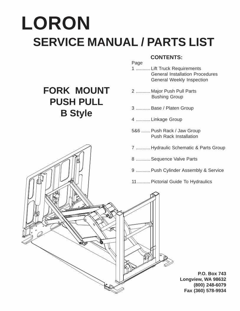
LORONSERVICE MANUAL / PARTS LIST
P.O. Box 743Longview, WA 98632
(800) 248-6079Fax (360) 578-9934
Page1 ........... Lift Truck Requirements
General Installation ProceduresGeneral Weekly Inspection
2 ........... Major Push Pull PartsBushing Group
3 ........... Base / Platen Group
4 ........... Linkage Group
5&6 ....... Push Rack / Jaw GroupPush Rack Installation
7 ........... Hydraulic Schematic & Parts Group
8 ........... Sequence Valve Parts
9 ........... Push Cylinder Assembly & Service
11 .......... Pictorial Guide To Hydraulics
CONTENTS:
FORK MOUNTPUSH PULL
B Style

1
LIFT TRUCK REQUIREMENTS
PUSH PULL HYDRAULICS
Hydraulic fluid: petroleum based hydraulicfluid onlyHydraulic supply group: includes hoses andtake-up - one set for each function
Recommended truck pressure: 2000 to 2500PSI (135 to 170 bar)Oil volume: 7-10 GPM (26.5 to 38 l/min)
GENERAL INSTALLATION PROCEDURES
1. Platens require support of the truck forks. Forks need to be 1.5" to 2.0" (38mm to 50mm)thick X 4.0" to 6.0" (100mm to 152mm) wide and within 6.0" (152mm) of usable length. Donot exceed usable length. Align forks with attachment fork pockets; drive forward until forksare completely inserted into fork pockets. Lower mast, shut off truck and engage parkingbrake.
2. Engage attachment lower retainers.
3. Attach truck supply group (take-up) to hoses supplied on the attachment base.
4. Standing clear of the Push Pull attachment cycle the attachment in and out several times todistribute the hydraulic oil. Use caution because partially filled hydraulic lines may causeerratic movement.
CAPACITY
Capacity shown on the Push Pull name plateis for the Push Pull only. Load carryingcapacity of the attachment depends uponthe lift truck forks. Load weight plus attach-ment weight must never exceed the ratedcapacity of the forks. The combined truckand Push Pull capacity is provided by the lifttruck manufacturer.
GENERAL WEEKLY INSPECTION AND MAINTENANCE
1. Check all hydraulic fittings, hoses, cylinders and valves for leakage - repair or replace asrequired.
2. Check hoses for pinch points and signs of wear. Replace worn or damaged hoses.
3. All bolts should be checked and tightened as required.
4. Check all weld joints for signs of cracking - paying close attention to the linkage group weldsand all platen welds.
Auxiliary valves: 1 Function = a single auxiliaryvalve

2
WEEKLY SERVICE:All bushings are constructedof self-lubricating material -NO SERVICE REQUIRED
BUSHING PARTS LIST
MAJOR PUSH PULL PARTS & BUSHING GROUP
LINKAGEBASE
PUSH CYLINDERS
6 7
PUSH RACK
GRIPPER CYLINDERS
GRIPPER BAR
GRIPPER SHOE
GRIPPER JAW
1
23
4
PLATENS
RETAINER
5
NO. QTY PART NO. DESCRIPTION1 2 100785.2 Bushings
2 2 100785.2
3 2 100785.1
4 2 100785.9
5 2 100785.2
6 2 100785.2
7 2 100785.3 Bushings

3
1
2 3
4
1110
58
6 7
WEEKLY SERVICE:Check and tighten all bolts.
9
BASE / PLATEN GROUP
**See customer packet for part number.
BASE / PLATEN GROUP PARTS LIST
N O. Q T Y PA R T N O . D E S C R IP T IO N1 1 ** B as e W e ld me nt
2 5 11 G .08 36 S oc k et Hea d B olt
3 5 17 D .08 E s na Nut
4 2 10 08 70 Retaine r
5 2 10 39 63 B all L oc k P in
6 2 10 09 21 C le vis P in
7 2 1 00 6 20 .G 16 Ro ll P in
8 4 2 F.10 P la in Wa s he r
9 1 ** P la te n W e ld me nt
10 1 10 42 02 S him (a s re q ui red )
11 1 10 4 20 2.1 S him (a s re q ui red )

4
LINKAGE GROUP
WEEKLY SERVICE:Grease slide block channels(items 18 & 19) weekly or asrequired.
LINKAGE GROUP PARTS LIST
N O. Q T Y PA R T N O . D E S C R IP T IO N1 1 10 02 09 Re ar P us h A rm
2 1 10 06 37 Re ar R eg ula tor RH
3 1 10 06 36 Rea r Re gulator L H
4 1 10 02 08 Front P us h A rm RH
5 1 10 02 07 Fro nt P ush A rm L H
6 1 10 06 62 Fro nt Re gula to r
7 1 10 02 67 Reg ula to r B ra ck e t
8 6 10 0 66 3.2 C hrom e P in
9 4 10 0 66 3.3 C hrom e P in
10 2 10 07 27 C hrom e P in
11 6 1 C .06 16 He x Hea d B olt
12 4 2 5 G .06 16 B utto n Hea d B olt
13 2 2 5 G .06 14 B utto n Hea d B olt
14 2 11 G .08 24 S oc k et Hea d B olt
15 12 4E .06 Lo ckwa s he r
16 2 1 6E .08 Hig h C o lla r Lo c kwa s he r
17 8 1 00 6 65 .38 Thrus t W as her /S him
18 2 10 04 65 S li de B lo c k (P us h Rac k )
19 2 10 04 64 S lide B loc k (B a se )
20 12 10 1 29 4.5 L oc k P in

5
NO. QTY PART NO. DESCRIPTION1 1 ** Push Rack2 1 * 103868 Gripper Jaw3 1 * 103530 Gripper Bar4 1 * 103873 Gripper Shoe5 10 11G.0820 Socket Head Bolt6 10 16E.08 High Collar Lockwasher7 7 25GN.0508 Button Head Nylok Bolt8 2 104130 Plastic Slide9 4 104131.1 Shim
WEEKLY SERVICE:Check and tighten jaw andgripper shoe mounting bolts.Check gripper shoe for wearand replace if badly worn.
* For use with standard 40" (1016mm) wide push rack.** See customer packet for part number of push rack
PUSH RACK / JAW PARTS LIST
PUSH RACK / JAW GROUP
6
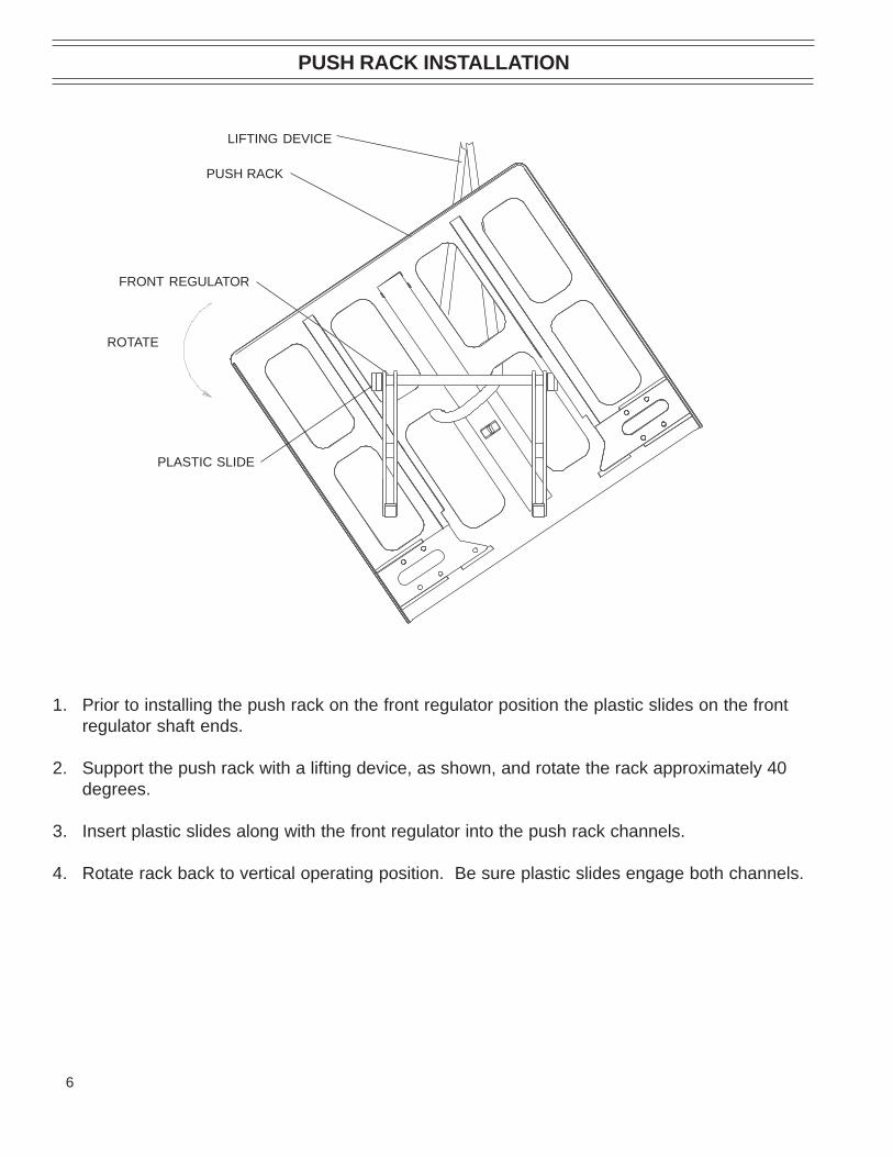
LIFTING DEVICE
1. Prior to installing the push rack on the front regulator position the plastic slides on the frontregulator shaft ends.
2. Support the push rack with a lifting device, as shown, and rotate the rack approximately 40degrees.
3. Insert plastic slides along with the front regulator into the push rack channels.
4. Rotate rack back to vertical operating position. Be sure plastic slides engage both channels.
ROTATE
PUSH RACK INSTALLATION
PLASTIC SLIDE
PUSH RACK
FRONT REGULATOR

7
HYDRAULIC SCHEMATIC & PARTS GROUP
WEEKLY SERVICE:Check hoses for fraying, cuts,bulges and badly worn areas.WARNING: Use onlyLORON HOSES or PARKERPARFLEX #560 WIREREINFORCED HOSE forreplacement hoses.
** See customer packet for Push Cylinder part number.
HYDRAULIC GROUP PARTS LIST
N O. QT Y PA R T N O. D E S C R IP T ION1 1 1 00 67 4.01 90 Ho se A ssem b ly
2 1 1 02 70 2.01 68 Ho se A ssem b ly
3 1 1 02 70 2.03 10 Ho se A ssem b ly
4 2 1 00 67 4.00 90 Ho se A ssem b ly
5 1 1 00 67 4.04 80 Ho se A ssem b ly
6 1 1 00 67 4.07 40 Ho se A ssem b ly
7 1 1 00 67 4.01 30 Ho se A ssem b ly
8 1 1 00 67 4.02 70 Ho se A ssem b ly
9 1 1 02 70 2.02 02 Ho se A ssem b ly
10 1 1 00 67 4.04 50 Ho se A ssem b ly
11 1 1 02 70 2.02 68 Ho se A ssem b ly
12 10 1 00 09 5 .05 9 0 D eg ree E lbo w
13 2 1 00 67 8 .05 B ra nch Tee
14 2 1 00 67 6 .05 S tra ig ht Thre ad A d ap te r
15 1 10 06 69 Junct io n B lo ck
16 2 1 00 74 4 .05 B ulkhe ad S traig ht
17 1 1 00 23 8 .05 45 D eg re e S w ivel
18 1 10 06 79 S eq uence Va lve
19 2 ** P ush C ylinde r
20 2 10 01 06 Grip pe r C ylinde r
21 2 10 06 7 7.1 B ra nch Tee
22 1 10 34 38 Ho se C li p (no t sho wn)
23 1 2 5G.05 20 B utto n Hea d B olt (no t sho wn)
24 1 1 7 D .05 E sna Nut (no t sho wn)

8
SEQUENCE VALVE PARTS & SCHEMATIC
SERVICE NOTE:Lubricate parts prior toassembly with STP
1
2
3 4
5
6
7
8
SEQUENCE VALVE SCHEMATIC
* Sequence Valve Seal Kit 103218
SEQUENCE VALVE PARTS
9 10
12
11
NO. QTY PART NO. DESCRIPTION1 1 103220 Valve Body
*2 1 100030.4 O-Ring Seal
*3 1 100029.107 O-Ring Seal
*4 1 100028.107 Back-up Ring
5 1 103222 Push Rod
6 1 103223 Plug
7 1 103219 Relief Cartridge
*8 1 103221 Cartridge Seal Kit
9 2 4E.05 Lockwasher Lsp
10 2 25G.0524 Button Head Bolt Lsp
11 1 103824.1 Actuator Rod
12 1 100574.82 Cotter Pin Lsp

9
PUSH CYLINDER ASSEMBLY & SERVICE
Torque to 200 ft-lbs(27.7 kg-m)
* Seal Kit=102182 (Items 7 thru 11)
* Seal Kit=102183 (Items 7 thru 11)
3500# PUSH CYLINDER
4500# PUSH CYLINDER
CYLINDER SERVICE
** See customer packet for part number of piston.
• Prior to assembly lubricate seals, cylinderbore, & rod with STP.
• Inspect all parts for scratches, nicks, andgouges - replace damaged components.
• Inspect cylinder bore & rod for scoring -replace if scored.
• Avoid damage to seal grooves - use a dullscrewdriver for seal removal.
• Torque piston nut to 200 ft-lbs. (27.7 kg-m)
• Gland nut tightening procedure:
Using spanner wrench number:103225.2 for 2.25" (57mm) bore cylinder103225.1 for 2.50" (63.5mm) bore cylinder- turn gland nut until tight and then strike theend of the spanner wrench with a hammerto further tighten.
NO. QTY PART NO. DESCRIPTION1 1 102241 Rod Weldment
2 1 103201 Gland Nut
3 1 104043 Tube Weldment
4 1 ** Piston
5 1 100785.3 Bushing
6 1 100785.2 Bushing
*7 1 100031.5 Polypak BS Seal
*8 1 101421.3 PSP Piston Seal
*9 1 100029.12 O-Ring
*10 1 18D.12 Locknut
*11 1 103208.4 Wiper Ring
NO. QTY PART NO. DESCRIPTION1 1 102241 Rod Weldment
2 1 102242 Gland Nut
3 1 103994 Tube Weldment
4 1 ** Piston
5 1 100785.3 Bushing
6 1 100785.2 Bushing
*7 1 100031.5 Polypak BS Seal
*8 1 101421.4 PSP Piston Seal
*9 1 100029.1 O-Ring
*10 1 18D.12 Locknut
*11 1 103208.4 Wiper Ring

10
NOTES

11
PICTORIAL GUIDE TO PUSH PULL HYDRAULICS

P.O. BOX 743 LONGVIEW, WASHINGTON 98632( 800 ) 248-6079( 360 ) 423-6079( 360 ) 578-9934
"Excellence in Action"
FAX
LORON