public works technical bulletin 200-1-25 1 … · public works technical bulletin 200-1-25 1...
TRANSCRIPT

PUBLIC WORKS TECHNICAL BULLETIN 200-1-25 1 DECEMBER 2003
FUEL TANKER PURGING FACILITIES — LESSONS LEARNED

Public Works Technical Bulletins are published by the U.S. Army Corps of Engineers, 441 G Street, NW, Washington, DC 20314-1000. They are intended to provide information on specific topics in areas of Facilities Engineering and Public Works. They are not intended to establish new Department of Army policy.
DEPARTMENT OF THE ARMY U.S. Army Corps of Engineers
441 G Street, NW Washington, DC 20314-1000
CEMP-R
Public Works Technical Bulletin 1 December 2003 No. 200-1-25
FACILITIES ENGINEERING Environment
FUEL TANKER PURGING FACILITIES — LESSONS LEARNED
1. Purpose. This Public Works Technical Bulletin (PWTB) transmits information on design and operation lessons learned at existing fuel tanker purging facilities. Due to recent additions to the Clean Water Act regulations, it is likely that new purging facilities will be constructed or existing purging facilities will be retrofitted. It is important that the successes and failures of past facilities are considered when new facilities are planned and designed.
2. Applicability. This PWTB applies to all U.S. Army offices responsible for the planning, design, or operation of purging facilities for transportation fuel tankers.
3. References.
a. Army Regulation (AR) 200-1, “Environmental Protection and Enhancement,” 21 February 1997.
b. See additional references in Appendix A, paragraph 5.
4. Discussion.
a. Vehicles used to haul fuel over the road, typically called fuel tankers, occasionally have to be cleaned to remove residual fuel and fuel vapors. This process is called purging. Purging is normally done when a fuel tanker requires maintenance or repair. It is also needed when the fuel hauled is changed to another fuel, or to prepare a fuel tanker for transport by rail or ship. In the past, Army installations have dedicated existing washracks for purging fuel tankers, have constructed new or retrofitted existing facilities, or have purchased off-the-shelf purging equipment.
b. The purging process generates wastewater contaminated with fuel that must be treated for discharge to a sanitary sewer. Purging facilities are subject to Clean Water Act pretreatment
PWTB 200-1-25 1 December 2003
regulations, including: the 40 CFR 403 general limitations for pretreated industrial wastewater; the specific requirements of a Publicly Owned Treatment Works (POTW) pretreatment program; and the Transportation Equipment Cleaning Rule (TEC Rule). Many of the Army’s purging facilities may not be in compliance with these newer pretreatment requirements and will require upgrades.
c. Because there is no standard design or design guidance for purging facilities, this PWTB provides installations with lessons learned information for consideration when future purging facility projects are planned. Appendix A of this PWTB is a summary of the types of facilities and equipment that are in use or have been tested at Army installations, and a description of the design and operation lessons learned at those sites. Some of the key points of Appendix A are as follows:
(1) Existing washracks may be acceptable as purging facilities at small installations where only a few vehicles are purged per year.
(2) Several options will improve purging operation, including: increasing size of fill piping; using a high pressure sprayer; heating purging water; using a purging chemical; and removing vapors with a vacuum system.
(3) Recycling purging liquid will help achieve compliance, pollution prevention, and sustainability goals.
5. Points of Contact. HQUSACE is the proponent for this document. POC at HQUSACE is Bob Fenlason, CEMP-RI, 202-761-0206, or e-mail: [email protected]. Questions and comments regarding this subject should be directed to the technical POC: Gary L. Gerdes, 217-398-5430 or 800-872-2375, e-mail: [email protected], who is at the U.S. Army Engineer Research and Development Center, Construction Engineering Research Laboratory, Champaign, IL.
FOR THE COMMANDER:
DONALD L. BASHAM, P.E. Chief, Engineering and Construction Division Directorate of Civil Works
2

PWTB 200-1-25 1 December 2003
3
APPENDIX A
Fuel Tanker Purging Facilities — Lessons Learned
1. Background.
a. Vehicles used to haul fuel over the road, typically called fuel tankers, occasionally have to be cleaned or purged to remove residual fuel and fuel vapors. This purging process is done primarily when a fuel tanker requires maintenance or repair. Purging is also needed when the fuel being hauled is changed to another fuel, or to prepare a fuel tanker for transport by rail or ship. Because re-fueling is an integral part of most maneuver training exercises, most Army installations have on-post transportation units or forward support units that are assigned to carry fuel to the tactical units during training exercises. For this reason, installations usually have some sort of facility for purging tankers.
b. Typically, the purging process consists of filling or partially filling the fuel tank with water or water with a purging chemical added, and then agitating that liquid by driving the fuel tanker around the installation. The used purging liquid is then drained from the tank, and the process is repeated a second time. When the tank is completely drained, it is tested for the presence of fuel vapors. If vapors are still present, the fill and drain process may be repeated, or the tanker may simply be left to stand with all valves and hatches open to allow the vapors to dissipate. The object of purging is to achieve a fuel vapor level that meets the safety requirements set by the maintenance organization(s) on the installation. [NOTE: In this document, “purging liquid” refers to water or water with a purging chemical added that is used to purge a tanker.]
c. The purging process can be very time consuming. The fuel tanks range in capacity from a 525-gallon (gal) fuel pod to a 7,500-gal M1062 semi-trailer tanker. The larger tanks can take hours to fill with conventional hoses at a washrack. After the rinsing process is complete, it can take more time (even overnight) for the vapors to dissipate and reach an acceptable level. The conventional purging process is not expedient by any means. One reason to upgrade a purging facility is to decrease the process time, which contributes to improved readiness.
d. The purging process will generate a large volume of fuel-contaminated wastewater that must be pretreated prior to discharge to a sanitary sewer. The fuel tanks are emptied of used purging liquid as quickly as possible, causing high flows that can exceed the design capacity of a washrack oil/water separator (OWS). If purging chemicals are used, they may emulsify the fuel, making it much more difficult to remove the fuel from the used purging liquid in a simple gravity OWS.
PWTB 200-1-25 1 December 2003
4
e. Facilities used for purging normally discharge to domestic wastewater treatment systems, subjecting them to several pretreatment regulations. The most prominent of those are:
(1) 40 CFR 403. The general limitations for discharging pretreated industrial wastewater to a treatment works, as specified in 40 CFR 403, state that pretreatment must remove contaminants (such as fuel) that will upset or pass through the receiving treatment works.
(2) TEC Rule. Stringent wastewater pretreatment discharge limits set by the Transportation Equipment Cleaning Rule (TEC Rule) will affect an Army purging facility that discharges more than 100,000 gal/year to a treatment system. (See Section 3. a.)
(3) Pretreatment Program Limits. Privatization of the Army’s wastewater collection systems may affect purging facilities. After privatization, a Federally Owned Treatment Works (FOTW) becomes a Publicly Owned Treatment Works (POTW). The POTW can have, and in many cases is required to have, a pretreatment program in which specific pretreatment discharge limits are imposed on industrial sources, such as a purging facility.
(4) MP&M Rule. The recently promulgated Metal Products and Machinery Rule (MP&M Rule) had been expected to impact all Army purging facilities but will not. It will affect only those facilities that discharge directly to the environment.
f. Some installations have incorporated recycle capability at their facilities to reduce the amount of water used and wastewater generated. Recycling purging facilities can operate for long periods of time without having to discharge.
2. Types of Purging Facilities and Associated Lessons Learned.
a. Washrack
(1) The most commonly used structure for purging fuel tankers is an existing washrack and associated OWS. A washrack has the bare essentials for purging: a water spigot and hose for filling the tank, and an OWS to pretreat the waste-purging water. The advantages of using an existing washrack are that it meets the minimal functional requirements and requires little or no capital expenditure. Figure 1 shows a washrack that has been dedicated to purging, with a security fence to control its use.

PWTB 200-1-25 1 December 2003
Figure 1 – Fort Lee, VA, washrack dedicated for use as a purging facility
(2) Disadvantages to using an existing washrack for purging are:
– Hoses at washracks are generally small, with flows in the 5 to 20 gal per minute (gpm) range. Filling a large fuel tank is very time consuming, making the purging process labor intensive. As Figure 2 shows, existing wash hoses have been replaced, in some cases, by a larger diameter pipe and aboveground fill hoses to increase the water flow. Fill times are considerably shorter at this facility, making the purging process much less labor intensive.
– The high flow from dumping the purging liquid may exceed the treatment capacity of the OWS. These surges in flow can send slugs of petroleum, oils, and lubricants (POL) into the sanitary sewer, violating the discharge limits of most applicable pretreatment regulations. Before a washrack is used as a purging facility, existing pretreatment should be evaluated, then upgraded, if necessary, as a slug control measure. To determine whether an existing OWS is suitable to pretreat the high flows from purging, refer to the “Joint Service Oil/Water Separator Guidance Document,” which is Army Environmental Center report number SFIM-AEC-EQ-CR-200010. That document calls for a minimum of 45 minutes detention in a simple gravity OWS. Batch treatment of purging liquid should be considered as an alternative to the normal plug flow through an OWS. If the total volume of used purging liquid generated during the purge process is less than the total volume of the OWS, the batch treatment is essentially being provided. [NOTE: Purging facility operation should be addressed in an installation’s Slug Control Plan.]
5

PWTB 200-1-25 1 December 2003
Figure 2 – Existing washrack modified to decrease fill times
(3) Some washracks have stormwater diversion devices that prevent storm water from entering the sanitary sewer when the washrack is idle. It is important that these devices are in a non-bypass position when used purging liquid is dumped at the washrack. Some automatic stormwater diversion devices rely on flow to the wash hose(s) to change the position of the diversion valve. When water is not being used at the washrack, the valve is automatically positioned such that the washrack discharges to storm drainage. These devices are not compatible with purging. Since used purging liquid is normally dumped when there is no flow to the fill hoses, it would be diverted to storm drainage and would be in violation of Clean Water Act regulations. b. Recycling Purging Facility
(1) Recycling is an attractive option for a purging facility to minimize water usage and to control slug discharges to the sanitary sewer. Figure 3 shows a recycling purging facility at Hunter Army Airfield, GA. The aboveground elevated storage tank holds the recycled purging liquid. The large diameter piping can quickly fill the fuel tanker with purge water using gravity flow. One pump is required to move treated water from the gravity OWS to the storage tank. This facility is simple in design and does not require a trained operator.
6

PWTB 200-1-25 1 December 2003
Figure 3 – Hunter Army Airfield purging facility
(2) Two design problems occurred with the facility in Figure 3. When the recycle system accumulated excess water from storm events, water would overflow from the top of the elevated storage tank. No provision had been made to contain fuel that had accumulated on the surface of the water, so it overflowed with the water and contaminated the soil below the tank. A second problem was a lack of freeze protection. A make-up water valve was damaged during freezing weather because the make-up water piping was not freeze protected. Simple changes in piping corrected both of these design errors (see reference b).
(3) Figure 4 shows another purging facility with recycle capability. This facility was built using the same concept as the Hunter Army Airfield facility, but with the addition of a covered fill area to prevent stormwater inflow. It also used a more complex operating system to control the water levels in the two overhead storage tanks. Unfortunately, the control system was either poorly designed or improperly installed. The facility can be used only if the automatic controls are manually overridden. Control switches and level sensors are in a buried, cylindrical OWS and are not accessible for easy repair or reconfiguration. Also, the make-up water piping was installed without adequate back-flow prevention. It is likely that other piping was not installed according to design, and further prevented the system from operating correctly. Clearly the lesson learned at this facility is to keep the operating system simple and accessible.
7

PWTB 200-1-25 1 December 2003
Figure 4 – Purging facility with recycle treatment and covered fill area
(4) An example of a simple operating system is as follows. Recycled purge liquid is pumped from the treatment system (normally an OWS) directly to the storage tank when treatment is complete. The recycle pump would be controlled by a flow or float switch at the end of the treatment process. Inside the storage tank, a float switch is positioned near the top of the tank that actuates a drain valve when there is excess water in the storage tank. Inside the storage tank, a second float switch is positioned to open a valve to add make-up water to the tank when the level becomes too low. An even simpler system could rely on manual water level control in the storage tank with the help of a sight glass or volume gauge.
c. Commercial Off-the-Shelf Systems
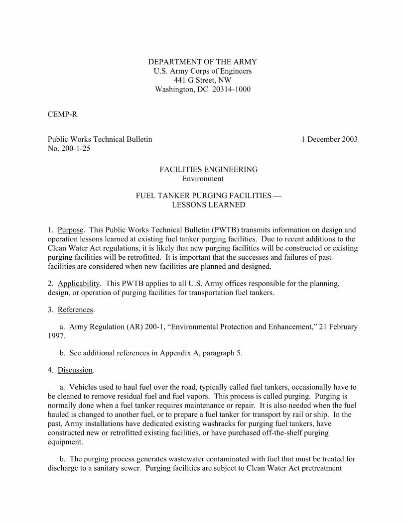
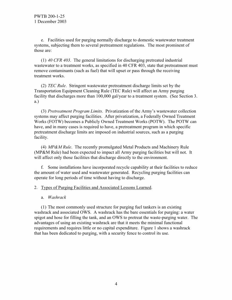
(1) Fort Hood, TX, has purchased and installed an off-the-shelf purging system (Figure 5) from 3i Cleaning Services, Inc. (Stockton, CA). This system has several desirable features, including:
– Recycle of water with purging chemical added and rinse water. Adding a purging chemical to the purge water will emulsify the residual fuel and shorten the overall time for the purging process. However, the purging chemical must be rinsed from the tank with clean water so the chemical will not contaminate the next load of fuel the tank will carry. (U.S. Army Tank-automotive and Armaments Command [TACOM] guidance does not specify how many rinses are adequate.) The 3i equipment has two
8
PWTB 200-1-25 1 December 2003
Figure 5 – Off-the-shelf purging system at Fort Hood, TX
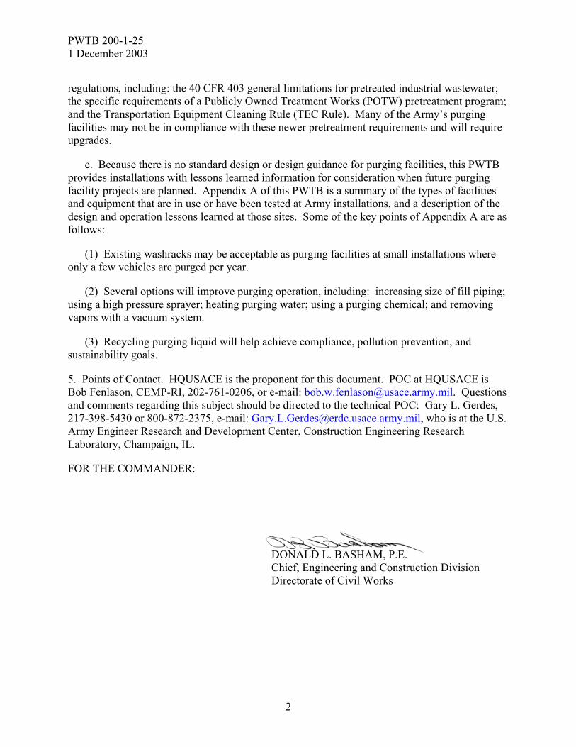
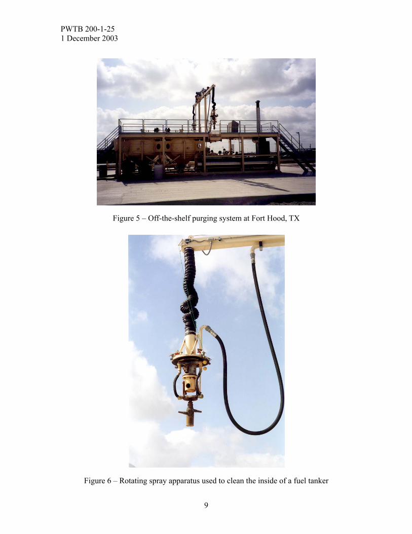
Figure 6 – Rotating spray apparatus used to clean the inside of a fuel tanker
9
PWTB 200-1-25 1 December 2003
10
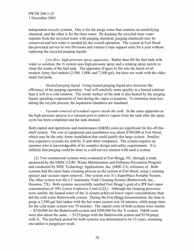
independent recycle systems. One is for the purge water that contains an emulsifying chemical, and the other is for the rinse water. By keeping the recycled rinse water separate from the recycled water with purging chemical, purging chemicals may be conserved and less water is needed for the overall operation. The system at Fort Hood has provided service to two Divisions and various Corps support units for a year without replacing the recycled purging liquids.
– Low flow, high-pressure spray apparatus. Rather than fill the fuel tank with water or solution, the 3i system uses high-pressure spray and a rotating spray nozzle to clean the inside of the fuel tank. The apparatus (Figure 6) fits into the hatch of all modern Army fuel tankers (2,500, 5,000, and 7,500 gal), but does not work with the older small fuel pods.
– Heated purging liquid. Using heated purging liquid also increases the efficiency of the purging operation. Fuel will emulsify more quickly in a heated solution than it will in a cold solution. The inside surface of the tank is also heated by the purging liquid, speeding evaporation of fuel during the vapor evacuation. To minimize heat loss during the recycle process, the separation chambers are insulated.
– Vacuum removal of residual vapors inside the tank. In the same apparatus as the high pressure sprayer is a vacuum port to remove vapors from the tank after the spray cycle has been completed and the tank drained.
Both capital and operations and maintenance (O&M) costs are significant for the off-the-shelf system. The cost of equipment and installation was about $780,000 at Fort Hood, which may be the only Army installation that could justify this large system. Smaller, less expensive systems are sold by 3i and other companies. The system requires an operator who is knowledgeable of its complex design and safety requirements. It is unlikely that purging could be done in a self-service manner with such a system.
(2) Two commercial systems were evaluated at Fort Bragg, NC, through a study sponsored by the ERDC/CERL Waste Minimization and Pollution Prevention Program and conducted by MSE Technology Applications, Inc. (MSE-TA; reference a). Both systems had the same basic cleaning process as the system at Fort Hood, using a rotating sprayer and vacuum vapor removal. One system was 3i’s SuperMacs Portable System. The other system was the LT Automatic Tank Cleaning System (Butterworth, Inc., Houston, TX). Both systems successfully reached Fort Bragg’s goal of a JP8 fuel vapor concentration of 10% Lower Explosive Limit (LEL). Although the cleaning processes were similar, the heated water of the 3i system achieved lower vapor concentrations than did the cold water Butterworth system. During the Fort Bragg demonstration, the time to purge a 2,500-gal fuel tanker with the hot water system was 54 minutes, while purge time for the cold water system was 70 minutes. The capital costs of both systems were similar — $320,000 for the Butterworth system and $309,000 for the 3i system. O&M costs were also about the same — $125/purge with the Butterworth system and $136/purge with 3i. The payback period for both systems was determined to be 15 years, assuming one tanker is purged per week.
PWTB 200-1-25 1 December 2003
11
3. Design Options for New or Retrofitted Purging Facilities.
a. Treatment of purging liquid. When the purging liquid is being dumped, it is necessary to empty the tank as quickly as possible – both to minimize the duration of the entire process, and to prevent fuel/water separation within the tanker while it is being drained. With dump valves fully open, flows to the treatment system may be 200 gpm or higher. Assuming a flow of 200 gpm, the size of a simple gravity OWS needed to maintain a 2-hour detention time would be 24,000 gal. To purge a 7,500-gal fuel tanker, assuming the tank is filled twice to about 2/3 full, the size of a simple gravity OWS needed to provide effective batch treatment would be the same as the volume of purge liquid used, or 10,000 gal. It is unlikely that more than one fuel tanker would be purged in a given day, so the used purging liquid would have several hours (possibly days) for the fuel to separate. Batch treatment of this waste stream will undoubtedly provide better fuel-water separation than plug flow treatment. Batch treatment can be used for both direct discharge to a sanitary sewer or for recycle.
Recycling purging liquid is recommended for several reasons, including wastewater minimization and water conservation. The most important reason to recycle may be to qualify for the TEC Rule “low flow exclusion.” According to that rule, if a purging facility discharges less than 100,000 gal per year, then it is excluded from having to meet specific pretreatment discharge limits. When purging one large tanker can release 10,000 gal of waste purging liquid, it does not take many tanker purges for a purging facility to discharge more than 100,000 gal per year. Therefore, most large Army installations probably do not qualify for the “low flow exclusion.”
Qualifying for exclusion from the TEC rule is desirable. The critical pretreatment discharge limit set by the TEC Rule is 26 milligrams per liter (mg/L) hexane-extractable nonpolar material (i.e., total petroleum hydrocarbons or TPH) (reference e). Since it is very difficult to achieve that level of treatment with a simple OWS, additional treatment would be required to discharge waste purging liquid to a sanitary sewer. The installation is faced with upgrading existing pretreatment equipment, and then providing O&M for that equipment. There may also be a requirement for annual sampling to demonstrate compliance with the discharge limit.
Using recycle to minimize discharges from a purging facility will very likely achieve the “low flow exclusion” at any installation. For example: Assume a large installation purges 50 fuel tankers per year. And assume the purge facility generates an average of 5,000 gal of wastewater per purge, so the discharge is 250,000 gal per year. Recycling the purge liquid only twice would decrease the annual discharge by two-thirds (to 83,000 gal per year) and achieve exemption from the TEC Rule. Based on the experience at Fort Hood, purge liquid can be recycled numerous times.
b. Purging liquid temperature. Heating the purging liquid increases the efficiency of the purging operation by heating the interior surface of the tanker and vaporizing the fuel on that surface. If a vapor concentration of 0% LEL is required for a successful purge, then heating the purging liquid should be considered. However, maintenance of

PWTB 200-1-25 1 December 2003
12
the water heater will add significant O&M costs. If a final vapor concentration of greater than 0% LEL is allowed, then hot water may not be worth the additional cost.
c. Fill or spray. Traditionally fuel tankers are purged by filling the fuel tank with purging liquid two or more times. The alternative to this process is to use commercial off-the-shelf purging equipment. The commercial systems use a high-pressure rotating sprayer to clean the interior surfaces of a tanker. The high-pressure spray systems use much less water, and significantly decrease the purging time. However, off-the-shelf systems are expensive to install and operate. It was thought during the CERL/MSE, Inc. study (reference a) that handheld high-pressure sprayers may also do an effective job of cleaning the tankers. Unfortunately, that method was not tested.
d. Vacuum vapor removal. After conventional fill-and-dump purging, it often takes overnight for the vapors in the tank to dissipate to an acceptable level. This is especially true if the goal is 0% LEL. When purging liquid is heated or high-pressure sprayer cleaning is used, the fuel vapor concentration inside the tank may be higher than when purging by filling with cold water, and it may take longer for vapors to dissipate. Vacuum vapor removal is a common feature on commercial purging systems because it accelerates the vapor reduction process. Normally, a vacuum hose assembly is attached to the fill port of the fuel tank. All other openings to the tank are left open to allow fresh air to enter the tank as the vapor laden air is suctioned out. A vacuum system probably does not increase the facility capital and operating costs as much as the high-pressure hot-water system. However, a vacuum system might be considered a point source for volatile organic air pollutants. Finally, any vacuum system used to remove vapors would have to be explosion proof.
4. Operation Options for New or Retrofitted Purging Facilities.
a. Purging chemicals. Chemicals are often used to emulsify the residual fuel in the tanker being purged. These emulsifiers increase the efficiency of the purging operation, since more fuel can be removed in the purging liquid, and thus less ventilation time is required. These chemical cleaning agents must be a “quick release” type emulsifier, i.e., they do not form stable emulsions and the fuel will separate from the cleaning solution after a relatively short period of detention (less than 1 hour). They are sometimes called “separator friendly.” Several chemicals have been used for purging. [NOTE: Whether any of these chemicals form stable emulsions has not been verified by the Corps of Engineers.] They are:
(1) Biodegradable purging solution NSN 7930-01-350-7034 or 7930-01-350-7035. This solution is mentioned in TACOM’s Ground Precautionary Message (GPM) regarding purging fuel tankers using a biodegradable purging chemical (reference c).
(2) Penetone ET
(3) Citrikleen (Penetone Corp.)
PWTB 200-1-25 1 December 2003
13
(4) Slix (Penetone Corp.)
(5) Simple Green. This chemical is not recommended for purging. It is generally believed that Simple Green creates very stable emulsions with petroleum, making it very difficult to pre-treat purging liquid.
Three of the above are made by Penetone Corporation and, according to Penetone, have been approved by TACOM for use as purging chemicals. A Penetone representative recommended Slix as its best purging product, though Penetone ET may release the fuel a little quicker in an OWS. Slix is used at the Fort Hood recycle purging facility.
b. % LEL goal. The allowable concentration of fuel vapor that may remain in a fuel tank after purging determines the extent of the purging process itself. The TACOM GPM clearly states that there should be no detectable fuel vapors in the tank (i.e., 0% LEL) at the end of the purging process. Some installations have instituted their own limit, however, such as the 10% LEL limit imposed at Fort Bragg. A 0% LEL goal must be considered when designing or retrofitting a purging facility. Use of a purging chemical, hot purging liquid, and/or vacuum removal of vapors may be necessary to achieve a 0% LEL goal in a timely manner.
5. References.
a. “Final Report – U.S. Army Construction Engineering Research Laboratory: Fort Bragg Army Post, Fuel Tank Purging System Feasibility Study/On-Site Demonstration”; MSE Technology Applications, Inc.; September 2002. (Unpublished)
b. Gerdes, Gary L., Jeff Grubich, Michelle J. Hanson, Stephen Cosper, Susan Bevelheimer, and Angelo Deguzman, “Survey of Fort Stewart and Hunter Army Airfield Oil/Water Separators; Findings and Recommendations,” ERDC/CERL Letter Report LR-01-1, January 2001.
c. “Information Paper – Ground Precautionary Message (GPM), TACOM Control No. 94-02 ‘Maintenance Advisory’ for Purging All Fuel Tankers Using a Biodegradable Purging Solution.”
d. “Joint Service Oil/Water Separator Guidance Document,” SFIM-AEC-EQ-CR-200010, U.S. Army Environmental Center, March 2001.
e. U.S. Army Environmental Center (USAEC) Technical Report SFIM-AEC-PC-CR-200169, “Army Implementation Information Paper – Effluent Limitations Guidelines, Pretreatment Standards, and New Source Performance Standards for the Transportation Equipment Cleaning Point Source Category; Final Rule (14 August 2000),” March 2002.

PWTB 200-1-25
14
1 December 2003
This publication may be reproduced.