acf maintenance bulletin tc-200 revision aamericanrailcar.com/images/informationbulletins/... ·...
TRANSCRIPT

ACF Maintenance Bulletin
TC-200 Revision A
ACF 200 Stub Sill Underframe Inspection, Repair, and Enhancement
May 5, 2006
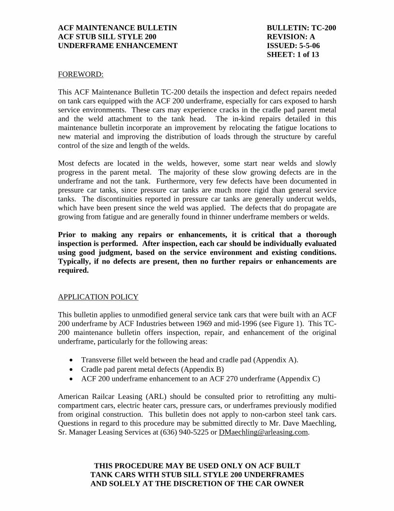
ACF MAINTENANCE BULLETIN BULLETIN: TC-200 ACF STUB SILL STYLE 200 REVISION: A UNDERFRAME ENHANCEMENT ISSUED: 5-5-06 SHEET: 1 of 13
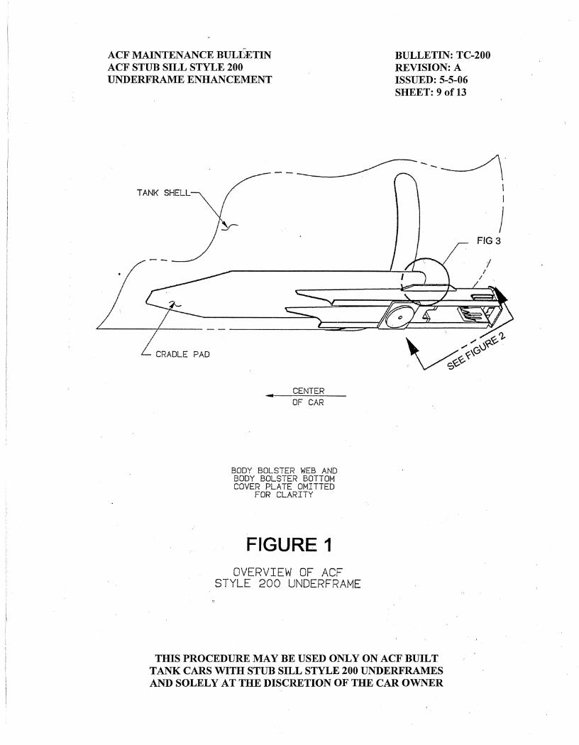
FOREWORD: This ACF Maintenance Bulletin TC-200 details the inspection and defect repairs needed on tank cars equipped with the ACF 200 underframe, especially for cars exposed to harsh service environments. These cars may experience cracks in the cradle pad parent metal and the weld attachment to the tank head. The in-kind repairs detailed in this maintenance bulletin incorporate an improvement by relocating the fatigue locations to new material and improving the distribution of loads through the structure by careful control of the size and length of the welds. Most defects are located in the welds, however, some start near welds and slowly progress in the parent metal. The majority of these slow growing defects are in the underframe and not the tank. Furthermore, very few defects have been documented in pressure car tanks, since pressure car tanks are much more rigid than general service tanks. The discontinuities reported in pressure car tanks are generally undercut welds, which have been present since the weld was applied. The defects that do propagate are growing from fatigue and are generally found in thinner underframe members or welds. Prior to making any repairs or enhancements, it is critical that a thorough inspection is performed. After inspection, each car should be individually evaluated using good judgment, based on the service environment and existing conditions. Typically, if no defects are present, then no further repairs or enhancements are required. APPLICATION POLICY This bulletin applies to unmodified general service tank cars that were built with an ACF 200 underframe by ACF Industries between 1969 and mid-1996 (see Figure 1). This TC-200 maintenance bulletin offers inspection, repair, and enhancement of the original underframe, particularly for the following areas:
• Transverse fillet weld between the head and cradle pad (Appendix A). • Cradle pad parent metal defects (Appendix B) • ACF 200 underframe enhancement to an ACF 270 underframe (Appendix C)
American Railcar Leasing (ARL) should be consulted prior to retrofitting any multi-compartment cars, electric heater cars, pressure cars, or underframes previously modified from original construction. This bulletin does not apply to non-carbon steel tank cars. Questions in regard to this procedure may be submitted directly to Mr. Dave Maechling, Sr. Manager Leasing Services at (636) 940-5225 or [email protected].
THIS PROCEDURE MAY BE USED ONLY ON ACF BUILT TANK CARS WITH STUB SILL STYLE 200 UNDERFRAMES AND SOLELY AT THE DISCRETION OF THE CAR OWNER
ACF MAINTENANCE BULLETIN BULLETIN: TC-200 ACF STUB SILL STYLE 200 REVISION: A UNDERFRAME ENHANCEMENT ISSUED: 5-5-06 SHEET: 2 of 13
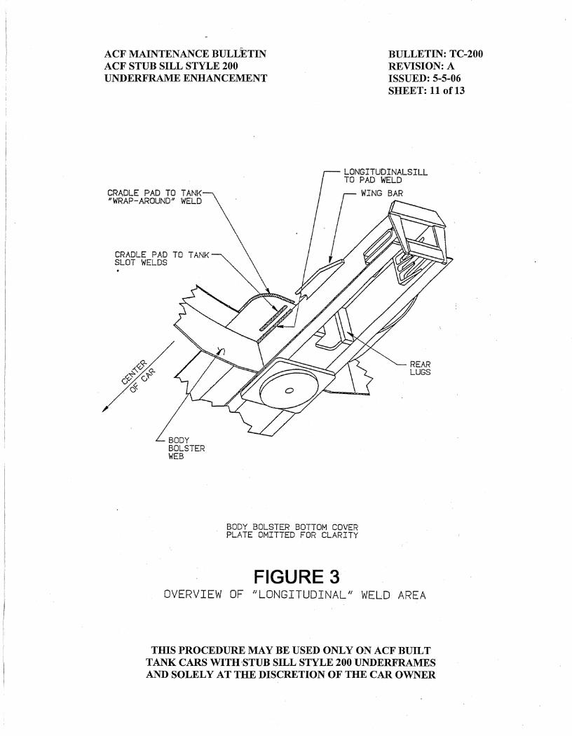
NOTICE: ACF Industries, Inc. does not warrant the performance of tank cars repaired to this procedure since workmanship, other maintenance factors, and end use of the cars are beyond the scope of this bulletin. INSTRUCTIONS: All work is to be performed in accordance with all applicable rules and regulations, including AAR Specification for Tank Cars, M-1002, Appendix R and W. Prior to beginning any repairs, a thorough AAR Field Manual Rule 88 and AAR SS-3 Stub Sill inspection must be performed. Steps 1 and 3 of this procedure require a qualified AAR Tank Car Welder and a qualified welding procedure. All NDT examinations throughout this procedure are to be performed in accordance with Appendix T by qualified personnel in accordance with a qualified procedure. Step 1: Transverse Weld Inspect the transverse weld for defects. If 5” of sound weld remains after all defects are removed and no other repairs that require stress relief in the area are necessary, then replacement of the transverse weld is not required. If stress relief is required or less than 5” of sound weld remains, then replace the 7” transverse cradle pad to tank weld (reference Figure 2) per Appendix A, attached. Step 2: Outboard Jacket Removal For cars with insulation, remove the jacket at the outboard cradle pad to sill weld area, reference Figure 3, to facilitate this modification. Remove the jacket from the draft sill web circumferentially around the tank approximately 24” and from directly over the edge of the body bolster bottom cover plate to the jacket head angle. Note: On cars with the flashing in this area it may be possible to cut two places and slide the jacket piece out of the other two sides. Jacket window size may decrease depending on specific car and worker familiarity with this modification.
THIS PROCEDURE MAY BE USED ONLY ON ACF BUILT TANK CARS WITH STUB SILL STYLE 200 UNDERFRAMES AND SOLELY AT THE DISCRETION OF THE CAR OWNER
ACF MAINTENANCE BULLETIN BULLETIN: TC-200 ACF STUB SILL STYLE 200 REVISION: A UNDERFRAME ENHANCEMENT ISSUED: 5-5-06 SHEET: 3 of 13
Step 3: Cradle Pad Slot Welds Many cars were built with full-filled slot welds, but some have fillet welds in a wide cradle pad slot. Inspect the slot welds, cradle pad, and tank to ensure the welds are structurally sound and that there are no parent metal or weld cracks. No repairs are required if no defects are found. If defects are present or the slot welds are missing, then repair as follows: A. Clean all rust scale, slag, paint, etc. from cradle pad, tank and existing weld as
required for welding. Remove any cracked or poor welds (i.e., porous, cold, etc.) by air arcing and grinding to sound metal.
Note: All metal that was gouged by the air arc must be ground smooth. B. Preheat the cradle pad and the tank to 200°F minimum and weld using AWS E-
7018 electrode. C. Each bead of multi-pass weld must be cleaned of slag and other loose deposits
before applying the next successive bead and after the final pass. D. Build weld to a full slot weld. If the top of weld protrudes past the surface of the
cradle pad by more than 1/8”, then grind weld flush with the surface of the cradle pad over the length of the weld.
E. The weld should be inspected by a member of the Q.A. staff. F. Stress relieve the slot weld repair. Step 4: Cradle Pad “Wrap-Around” Welds Inspect the cradle pad to tank shell “wrap around” welds, reference Figure 3, and remove the stick weld portion of this weld (if present). The existing stick weld may remain if it is a full 7/16” fillet weld with a good quality termination and the toe of the weld along the tank is of good quality. Undercutting and cold lap is not acceptable along the tank shell or at the cradle pad. This repair must be symmetric about the longitudinal centerline of the car. A. If a stick weld is not present, then ensure termination and toes of existing semi-
automatic weld have a good contour.
THIS PROCEDURE MAY BE USED ONLY ON ACF BUILT TANK CARS WITH STUB SILL STYLE 200 UNDERFRAMES AND SOLELY AT THE DISCRETION OF THE CAR OWNER
ACF MAINTENANCE BULLETIN BULLETIN: TC-200 ACF STUB SILL STYLE 200 REVISION: A UNDERFRAME ENHANCEMENT ISSUED: 5-5-06 SHEET: 4 of 13
B. If the stick weld portion of the cradle pad to tank shell “wrap around” weld is to be removed, then this should be accomplished by grinding only. Gouging the body of the weld is acceptable, provided the finish removal of the weld along the tank and cradle pad is performed by grinding and that all gouged areas are ground smooth. No gouging or grinding of the tank shell parent metal is permitted. Ensure termination and toe of semi-automatic weld has a good contour.
Step 5: Longitudinal Cradle Pad to Sill Weld Area, reference Figure 3 Inspect the end of the longitudinal weld for a 1” no-weld zone (NWZ) at the outboard end of the cradle pad. No repairs are required if no defects are found. If defects in the weld or parent metal are found, then repair as follows: A. Using a small diameter carbon arc rod, gouge the longitudinal weld attaching the
cradle pad to draft sill to create a 1” (NWZ) from the outboard edge of the cradle pad. The weld attaching the cradle pad to sill must be removed in the 1” NWZ. This is to be accomplished by removing sill metal as required, not the cradle pad parent material.
If after creating the 1” NWZ a defect still exists, then gouge to remove the
remaining defect. A minimum 2” long welding J-groove is required for proper weld terminations. If necessary, remove additional material as required to ensure a groove weld length of 2” minimum.
B. Grind sill web, cradle pad, and gouged groove to a smooth contour. C. Thoroughly inspect the cradle pad parent metal for any cracks and dye check as
required. A small hand held inspection mirror or a borescope may be required for this inspection. If any cracks are found, then repair all cracks per Appendix B, attached.
Note: If the wing bar was removed to facilitate a cradle pad repair, then do not
reapply the bar at this point, the wing bar will be reapplied in step 5, G, below. D. If required, replace the fillet and J-groove longitudinal weld that was removed
past the 1” NWZ in step 5, A, as follows: Note: This may not apply to all 4 corners of the car.
THIS PROCEDURE MAY BE USED ONLY ON ACF BUILT TANK CARS WITH STUB SILL STYLE 200 UNDERFRAMES AND SOLELY AT THE DISCRETION OF THE CAR OWNER
ACF MAINTENANCE BULLETIN BULLETIN: TC-200 ACF STUB SILL STYLE 200 REVISION: A UNDERFRAME ENHANCEMENT ISSUED: 5-5-06 SHEET: 5 of 13
1. The minimum weld length is 2” (reference step 5,A above), so that a 1” back-weld can be achieved on both ends.
2. Preheat area to 200°F minimum. 3. Apply a combination J-groove weld and 1/2” fillet weld using AWS E-7018
electrode, or E71T-1 (if clearance is adequate). After repairing the original defective weld, oversize the longitudinal weld size to a 1/2" fillet for a 6” length. Start at the 1” NWZ from the edge of the cradle pad and extend the 1/2” fillet weld inboard for 6”.
Note: The 1” NWZ from the edge of the cradle pad must be adhered to when repairing this weld.
4. Avoid undercutting or gouging the cradle pad. Note: It may be necessary to build the leg of the weld against the pad out
further than 1/2” to avoid undercutting the pad, or it may be necessary to remove a portion of the wing bar to gain access, reference Appendix B of this procedure as required.
5. Back-weld for a minimum 1” at starts and stops of weld. 6. Each bead of multi-pass weld must be cleaned of slag and other loose deposits
before applying the next successive bead and after the final pass. 7. The inboard termination of the newly applied weld should have a smooth
transition to the previously existing weld. The outboard terminations should align to form a “blunt” end.
E. When sill section replacement is required, preheat area to 200°F minimum and
build-up gouged out sill parent metal with AWS E-7018 electrode or E71T-1, if clearance is adequate. Do not tie the cradle pad to the sill web in the 1” NWZ.
Note: Care must be taken to tie this build-up weld into the existing weld
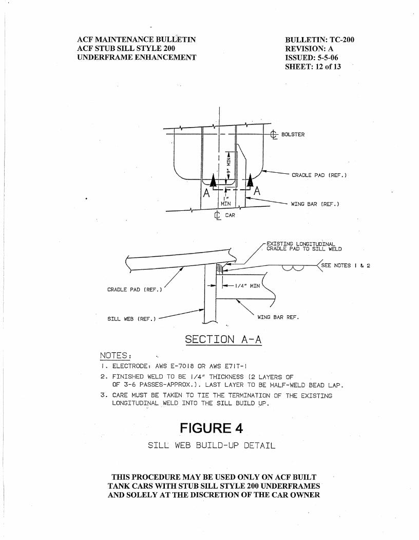
termination. F. If sill defects exist or the wing bar was removed, then build-up section of sill web
above the wing bar per Figure 4.
THIS PROCEDURE MAY BE USED ONLY ON ACF BUILT TANK CARS WITH STUB SILL STYLE 200 UNDERFRAMES AND SOLELY AT THE DISCRETION OF THE CAR OWNER
ACF MAINTENANCE BULLETIN BULLETIN: TC-200 ACF STUB SILL STYLE 200 REVISION: A UNDERFRAME ENHANCEMENT ISSUED: 5-5-06 SHEET: 6 of 13
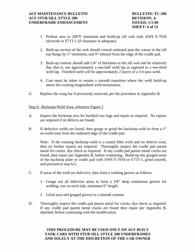
1. Preheat area to 200°F minimum and build-up sill web with AWS E-7018 electrode or E71T-1 (if clearance is adequate).
2. Built-up section of the web should extend outboard past the cutout in the sill
top flange by 1” minimum, and 9” inboard from the edge of the cradle pad. 3. Built-up contour should add 1/4" of thickness to the sill web and be relatively
flat, that is, use approximately a one-half weld lap as opposed to a one-third weld lap. Finished weld will be approximately 2 layers of a 3-6 pass weld.
4. Care must be taken to ensure a smooth transition where the weld build-up
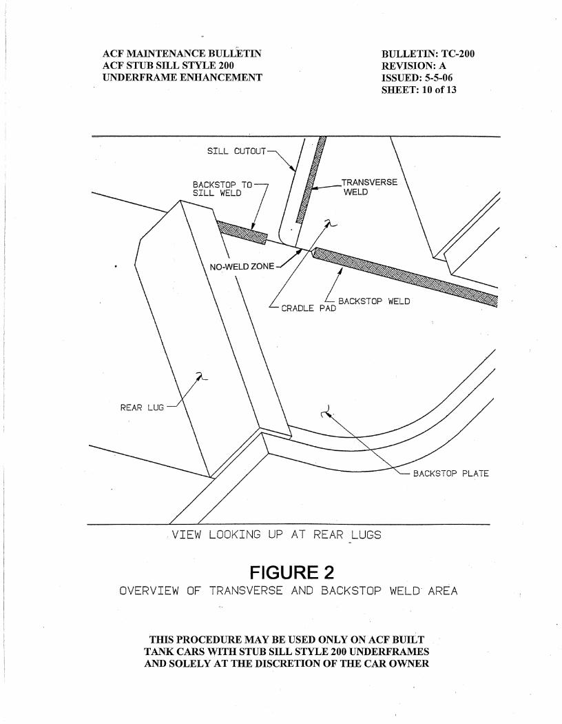
meets the existing longitudinal weld termination. G. Replace the wing bar if previously removed, per the procedure in Appendix B. Step 6: Backstop Weld Area, reference Figure 2 A. Inspect the backstop area for buckled rear lugs and repair as required. No repairs
are required if no defects are found. B. If defective welds are found, then gouge or grind the backstop weld to form a 1”
no-weld zone from the outboard edge of the cradle pad. Note: If the existing backstop weld is a sound fillet weld and no defects exist,
then no further repairs are required. Thoroughly inspect the cradle pad parent metal for cracks, dye check as required. If any cradle pad parent metal cracks are found, then repair per Appendix B, before continuing. Build-up any gouged areas of the backstop plate or cradle pad with AWS E-7018 or E71T-1, grind smooth, and proceed to step 6,G.
C. If areas of the weld are defective, then form a welding groove as follows: 1. Gouge out all defective areas to form a 3/8” deep continuous groove for
welding, one on each side, minimum 6” length. 2. Grind area and gouged groove to a smooth contour. D. Thoroughly inspect the cradle pad parent metal for cracks, dye check as required.
If any cradle pad parent metal cracks are found then repair per Appendix B, attached, before continuing with the modification.
THIS PROCEDURE MAY BE USED ONLY ON ACF BUILT TANK CARS WITH STUB SILL STYLE 200 UNDERFRAMES AND SOLELY AT THE DISCRETION OF THE CAR OWNER
ACF MAINTENANCE BULLETIN BULLETIN: TC-200 ACF STUB SILL STYLE 200 REVISION: A UNDERFRAME ENHANCEMENT ISSUED: 5-5-06 SHEET: 7 of 13
E. Build-up any gouged areas of the backstop plate or cradle pad with AWS E-7018
or E71T-1 and grind smooth. F. Repair the backstop weld (if required) as follows: 1. Preheat area to 200°F minimum and weld using AWS E-7018 or E71T-1. 2. In the groove gouged in step 6, C, above, apply a 3/8” bevel weld with a 1/2"
oversized fillet weld starting 1” from the edge of the cradle pad and extending inboard for the 6”.
3. Minimum weld length is 6”. 4. Avoid undercutting or gouging the cradle pad. 5. Each bead of multi-pass weld must be cleaned of slag and other loose deposits
before applying the next successive bead and after the final pass. 6. The inboard termination should have a smooth transition to the previously
existing weld. G. Have weld inspected by a member of the Q.A. staff. H. For cars that have a weld attaching the backstop plate to the draft sill (directly
behind the rear lug block, reference Figure 2) that is at least 2” in length. Ensure a sound weld attachment. If defective, then gouge and reweld with AWS E-7018 or E71T-1 as required.
I. For insulated cars, apply previously removed insulation and a new lap welded
jacket patch or modify the removed section of jacket, apply back-up strips and butt weld jacket patch. For cars with foam insulation apply 2” of Fiber Frax and 2” of fiberglass insulation.
Step 7: Inboard Cradle Pad Termination Inspect the inboard termination of the cradle pad. Repair any weld cracks found per Figure 5.
THIS PROCEDURE MAY BE USED ONLY ON ACF BUILT TANK CARS WITH STUB SILL STYLE 200 UNDERFRAMES AND SOLELY AT THE DISCRETION OF THE CAR OWNER

ACF MAINTENANCE BULLETIN BULLETIN: TC-200 ACF STUB SILL STYLE 200 REVISION: A UNDERFRAME ENHANCEMENT ISSUED: 5-5-06 SHEET: 8 of 13
Note: Insulated cars must have the insulation removed for this inspection and this step does not apply to cars that have a continuous cradle pad. A. If a crack exists in Area 1 (Figure 5), then remove the crack by gouging and/or
grinding the existing weld to the 45º line. Weld repair is not required. B. If a crack extends into Area 2 (Figure 5), then in accordance with Appendix R and
W repair the weld. The repair weld should not extend beyond the 45º line as shown in Figure 5.
Step 8: Finish A. Reapply all items previously removed for access purposes. B. Patch paint repair areas as required. C. Complete all documentation, including an AAR SS-3 form. Note that the
underframe style on the SS-3 form must be an ACF 200 for defects incurred prior to the P470 enhancement (Appendix C).
D. Review Appendix C “Application Policy” to determine if a P470 enhancement is
required.
THIS PROCEDURE MAY BE USED ONLY ON ACF BUILT TANK CARS WITH STUB SILL STYLE 200 UNDERFRAMES AND SOLELY AT THE DISCRETION OF THE CAR OWNER

ACF MAINTENANCE BULLETIN BULLETIN: TC-200 ACF STUB SILL STYLE 200 REVISION: A UNDERFRAME ENHANCEMENT ISSUED: 5-5-06 SHEET: A-1 of 5
APPLICATION POLICY This Appendix A details the recommended procedure for the replacement of the cradle pad to tank transverse attachment weld at the outboard end of the cradle pad, reference Figure 1 of the main body of this bulletin. INSTRUCTION 1. References – The following documents are required to perform this repair: A. AAR Specification for Tank Cars, Specification M-1002 B. A qualified dye penetrant examination procedure C A qualified welding procedure for tank welding 2. Personnel A. Personnel performing the welding of this procedure must be AAR tank car
certified welders. B. Personnel performing the dye penetrant examination must be certified in the
procedure used. 3. Equipment and Tools Required: A. Carbon air arc B. Grinders: 1. A small 3” or 4” disc type grinder, and 2. Either a small 90° angle die grinder or a short straight die grinder with
a 90° air inlet connection. Overall length of this grinder from end of the burr to the end of the air connection must be less than about 6 1/2". Both of these grinders should have a collet that will accept both 1/8” and 1/4" diameter shank grinding burrs.
C. Carbide tip grinding burrs
THIS PROCEDURE MAY BE USED ONLY ON ACF BUILT TANK CARS WITH STUB SILL STYLE 200 UNDERFRAMES AND SOLELY AT THE DISCRETION OF THE CAR OWNER
ACF MAINTENANCE BULLETIN BULLETIN: TC-200 ACF STUB SILL STYLE 200 REVISION: A UNDERFRAME ENHANCEMENT ISSUED: 5-5-06 SHEET: A-2 of 5
1. Ball nose cone with straight edge or a straight cone with straight edges – used to smooth the tank head and cradle pad after removal of weld (should be 1/4" shank).
2. Tree-shaped rounded end or barrel shaped – used to remove the
majority of any weld metal that is above the rear lug plate (should be 1/4" shank).
3. Ball type burr – used to blend and feather all transitions (should be
1/8” shank). D. Dye check kit E. Welding machine and equipment for SMAW F. AWS E-7018 electrode per AAR Appendix W G. Portable electrode oven H. Torch for preheating I. De-slagging tool and wire brush J. Stress relief equipment and supplies K. Hydrostatic tank test equipment L. Adequate lighting M. Appropriate safety equipment 3. Procedure for weld replacement A. Using carbon air-arc, remove the body of the weld over the entire length of
the weld and part of the cradle pad to form a 3/8” groove for welding. Do not gouge into the tank head parent metal.
B. Using the tree-shaped round end or barrel burr, remove the majority of the
weld metal and cradle pad parent metal that was not removed with the air arc. Do not grind into the tank head parent metal.
THIS PROCEDURE MAY BE USED ONLY ON ACF BUILT TANK CARS WITH STUB SILL STYLE 200 UNDERFRAMES AND SOLELY AT THE DISCRETION OF THE CAR OWNER
ACF MAINTENANCE BULLETIN BULLETIN: TC-200 ACF STUB SILL STYLE 200 REVISION: A UNDERFRAME ENHANCEMENT ISSUED: 5-5-06 SHEET: A-3 of 5
C. Using the small disc type grinder, grind the tank head to a smooth contour. This should remove most of the weld metal that is not close to the backstop plate. Do not grind into the tank head parent metal.
D. Using the straight side of the ball nose cone burr or the straight cone burr,
grind the tank head to a smooth contour over the rear lugs. Also use the point and side of the burr to remove the cradle pad parent metal and to “dig” the penetration out from between the tank and the cradle pad as required. The side of the burr should be used to back bevel the cradle pad, at least 3/8”. Do not grind into the tank head parent metal.
E. The tank head and cradle pad parent metal must be smooth for subsequent
dye check and no sharp edges should exist. Use the ball type burr to round any squared off edges and to form smooth transitions. Do not grind into the tank head parent metal.
F. Dye check the tank head 1. If no indication is found then remove the dye check and continue per
this instruction. 2. If an indication along the tank head is found, repair in accordance with
the applicable sections of Appendix R and W. G. Prior to welding, preheat area to 200°F minimum and verify with a
Tempilstik. H. Apply the transverse cradle pad to tank head weld per the following: 1. Weld using AWS E-7018 electrode per specific weld procedure being
used. Electrodes should be kept in a portable electrode oven in close proximity to the workstation.
2. Weld passes are to be applied per either sequence shown in Figure A-1
of this appendix. 3. Stringer passes are to have a minimum 1” start and stop and overall
weld length is to be at least 5” and no longer than a good quality termination with no visible undercutting can be applied, this length is approximately 7”.
THIS PROCEDURE MAY BE USED ONLY ON ACF BUILT TANK CARS WITH STUB SILL STYLE 200 UNDERFRAMES AND SOLELY AT THE DISCRETION OF THE CAR OWNER
ACF MAINTENANCE BULLETIN BULLETIN: TC-200 ACF STUB SILL STYLE 200 REVISION: A UNDERFRAME ENHANCEMENT ISSUED: 5-5-06 SHEET: A-4 of 5
4. Each bead of multi-pass weld must be cleaned of slag and other loose deposits before applying the next successive bead and after the final pass.
5. The final weld is to be a 3/8” groove weld with a 5/8” x 7/16” unequal
leg fillet weld. The toe of the fillet weld against the tank must be outboard of the previous toe location, approximately 5/8” from the end of the cradle pad. This weld will be approximately 12-18 passes and the last layer of passes must be built from the tank to the cradle pad. The terminations of each pass of weld must line up to form a “squared off” termination. If the welding is stopped for any length of time, then the area must be 200°F minimum before welding is continued.
I. Dye check the weld repair. J. Stress relieve the repair per Appendix W. K. Dye check the weld repair. L. Weld must be inspected by a member of the Quality Assurance staff prior to
out-shopping the car.
THIS PROCEDURE MAY BE USED ONLY ON ACF BUILT TANK CARS WITH STUB SILL STYLE 200 UNDERFRAMES AND SOLELY AT THE DISCRETION OF THE CAR OWNER


ACF MAINTENANCE BULLETIN BULLETIN: TC-200 ACF STUB SILL STYLE 200 REVISION: A UNDERFRAME ENHANCEMENT ISSUED: 5-5-06 SHEET: B-1 of 10
APPLICATION POLICY This Appendix B details the recommended procedure for the repair of cradle pad parent metal cracks. All cradle pad parent metal cracks must be repaired. INSTRUCTION A. Repair of crack 1. If the cradle pad parent metal crack is located above the wing bar, then
remove half or the entire wing bar and save for reapplication. If removing only half of the wing bar, then make the transverse cut out from the tank head far enough so that when reapplying the wing bar a weld can be made from the top for 100% penetration.
Note: Care must be taken when cutting the wing bar, to not gouge the
cradle pad or sill web. Placing an old piece of stress relief insulation (e.g., Kaowool) on top of wing bar will help cut down on sparks and slag falling when cutting.
Note: Most cracks in the cradle pad parent metal are accessible at this point,
however occasionally a crack is not accessible due to the backstop plate or the draft sill. If the crack is not accessible due to the backstop plate, it will be necessary to gain access per the procedure detailed in Section B below. If crack is not accessible due to the crack running above the sill web, it will be necessary to gain access per the procedure detailed in Section C, below.
2. Locate the ends of the fracture, dye penetrant is an acceptable method. Note: The cracks do not always extend to the outboard edge of the cradle
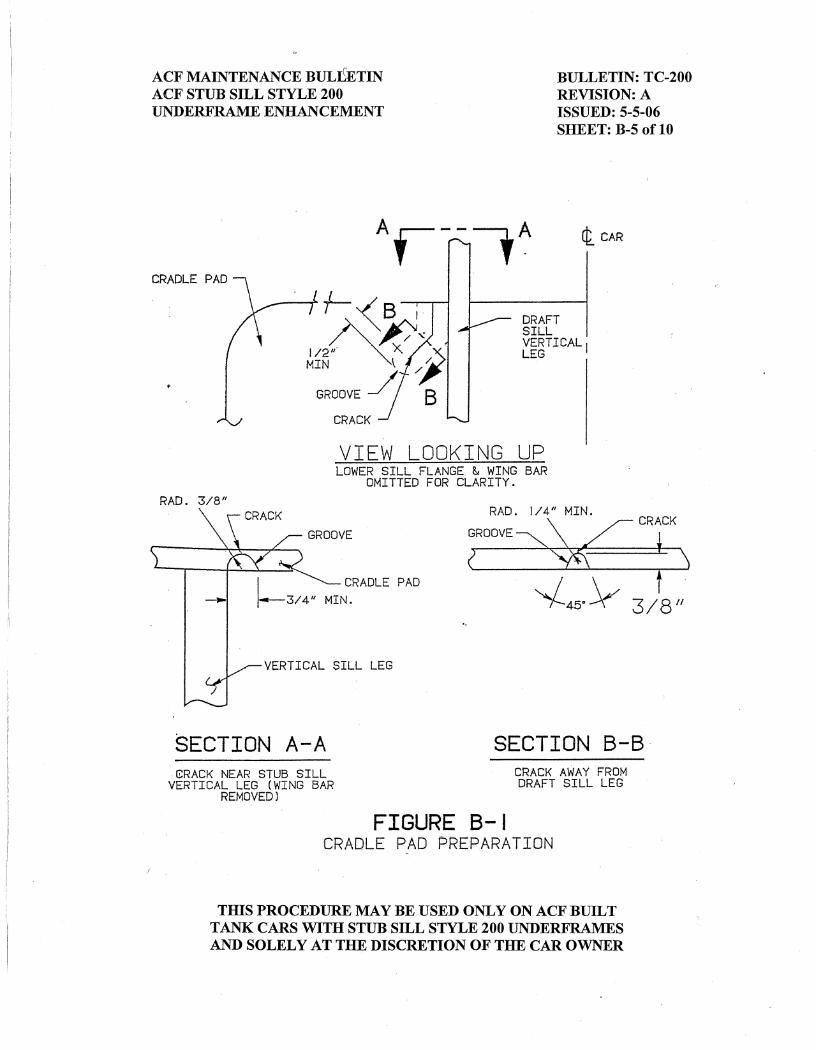
pad. 3. Form a groove 3/8” deep maximum, per Figure B-1 of this appendix.
Groove should extend past end of fracture by 1/2" minimum and be ground to have a smooth contour for subsequent dye check and welding.
4. Dye check to ensure the end of the fracture has been completely removed. 5. Remove dye check and preheat the cradle pad to 200°F minimum prior to
welding.
THIS PROCEDURE MAY BE USED ONLY ON ACF BUILT TANK CARS WITH STUB SILL STYLE 200 UNDERFRAMES AND SOLELY AT THE DISCRETION OF THE CAR OWNER
ACF MAINTENANCE BULLETIN BULLETIN: TC-200 ACF STUB SILL STYLE 200 REVISION: A UNDERFRAME ENHANCEMENT ISSUED: 5-5-06 SHEET: B-2 of 10
6. Repair weld the groove with AWS E-7018 or E71T-1 electrode using good,
sound welding practice, being careful not to burn through to tank. A runoff tab may be required to prevent destroying the edge of the cradle pad.
Note: Do not penetrate through the cradle pad (as this might nick the tank),
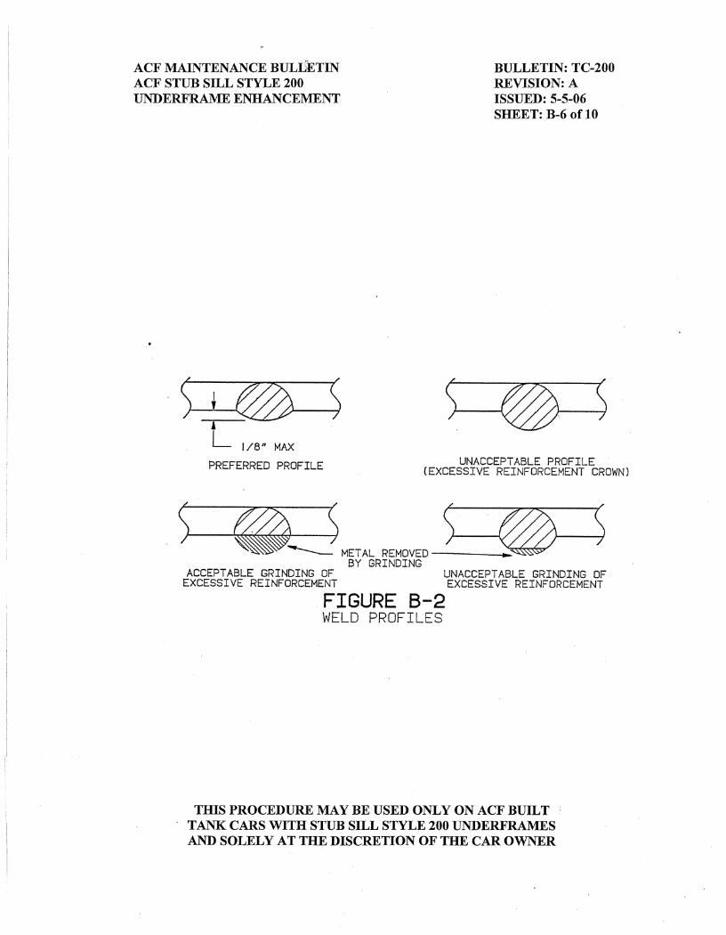
100% penetration is not required. 7. If after welding, the reinforcing crown is over 1/8”, then grind repair weld
flush with cradle pad surface. Do not grind just the top of the crown off, see Figure B-2.
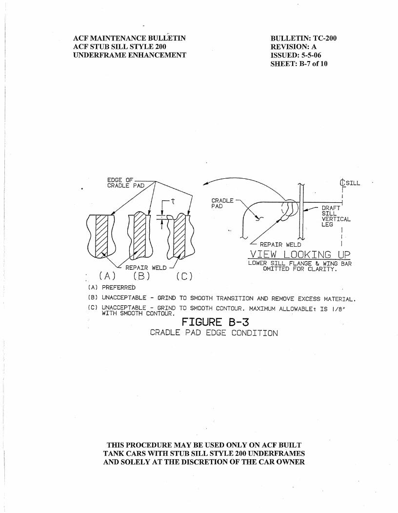
8. Ensure the edge of the cradle pad is smooth (i.e., that the termination of
repair weld does not notch the end of pad), see Figure B-3. Remove runoff tab (if used) and dress up with a die grinder as required.
9. Have weld inspected by a member of the Q.A. staff prior to reapplication of
wing bar. 10. Repair any gouges in sill by welding with E-7018 or E71T-1 and grind
repair welds flush. 11. When called in the main body of this bulletin to reapply the wing bar, then
reapply per Figure B-4 of this appendix. Note: Ensure bar is level, square and located approximately 3/4" from the
top of the sill. If new material is required for the wing bar, then it must conform to ASTM A-572 Grade 50 Type 2 Charpy V-notch to meet 15 ft.-lbs. min. at -30°F.
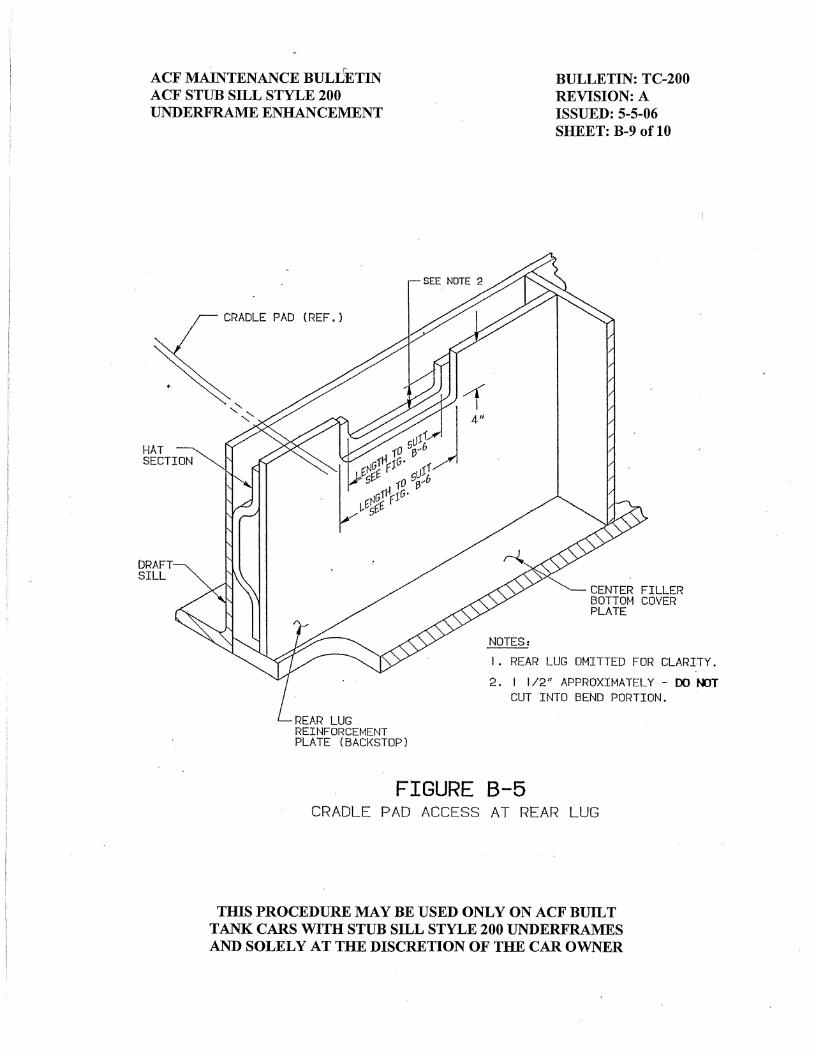
B. Cradle Pad Access at the Rear Lug When access between the rear lug and the vertical leg of the stub sill is required,
the following procedure should be applied, reference Figure B-5 of this appendix. 1. Using a carbon arc, “wash” away backstop plate 4” high by length required. Note: Care must be taken not to gouge through, into the “hat” section. 2. Using either a torch or a small diameter carbon-arc, cut straight flange
section of “hat” section for the length required, save piece for reapplication.
THIS PROCEDURE MAY BE USED ONLY ON ACF BUILT TANK CARS WITH STUB SILL STYLE 200 UNDERFRAMES AND SOLELY AT THE DISCRETION OF THE CAR OWNER
ACF MAINTENANCE BULLETIN BULLETIN: TC-200 ACF STUB SILL STYLE 200 REVISION: A UNDERFRAME ENHANCEMENT ISSUED: 5-5-06 SHEET: B-3 of 10
3. Prepare by grinding, the edges of the “hat” section, the backstop plate and
the removed piece of the “hat” section, to be reapplied. Note: All corners should have a 1” minimum radius. 4. After cradle pad repairs are made per Section A, apply 1/8” back-up strips
around the three cut sides of the “hat” section. 5. If the “hat” section was gouged or cut curing the removal of the backstop
plate, then build up gouged areas with AWS E-7018 or E71T-1 electrode and grind smooth.
6. Fabricate a replacement piece for the backstop plate of ASTM A-36 steel as
required and bevel edges for welding. 7. Apply 1/8” back-up strips around periphery of cutout as required; i.e., where
hat section cannot be used as the back-up bar. 8. Preheat area to 200°F minimum and weld the replacement section with
AWS E-7018 or E71T-1 electrode assuring 100% penetration and good alignment of the existing backstop plate and the replacement section.
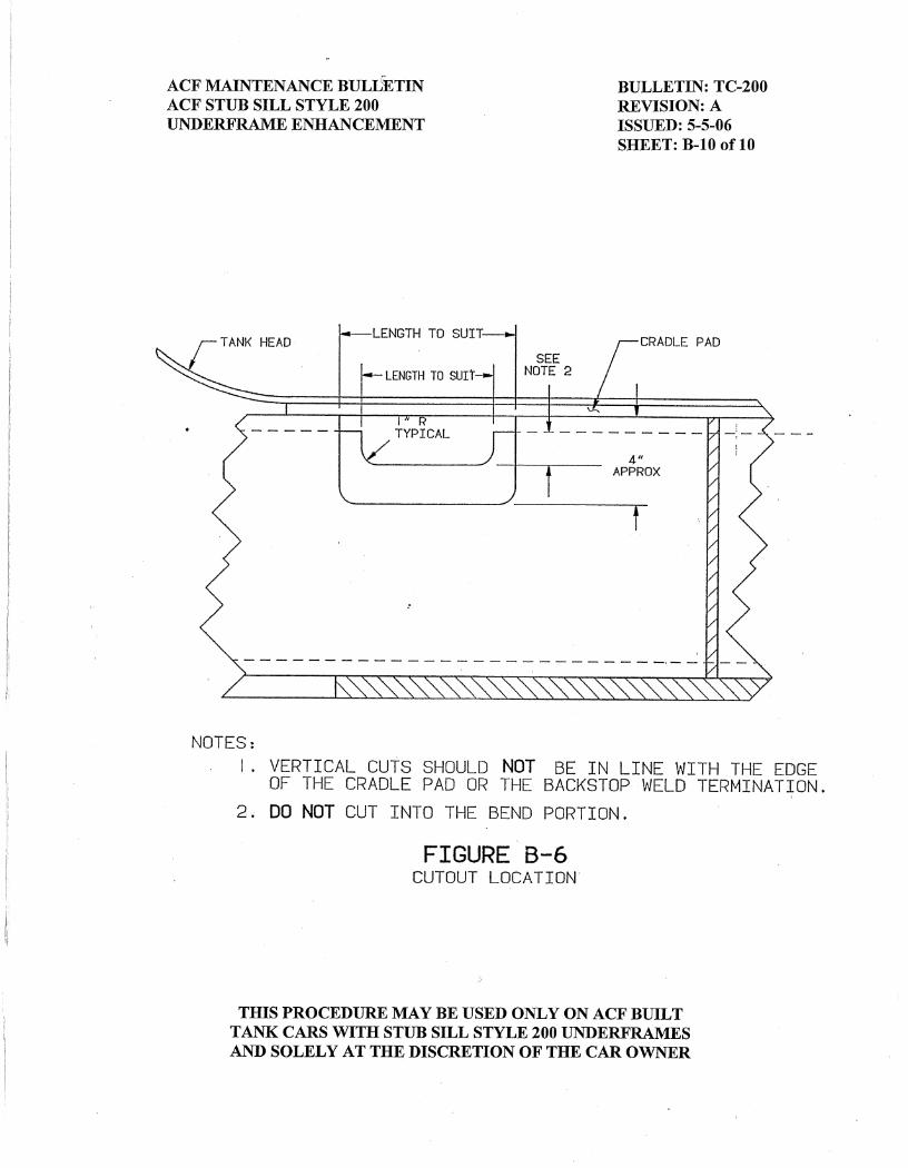
C. Cradle Pad Access at the Draft Sill Web When access above the draft sill web is required, that is, the crack is over the
vertical leg of the draft sill, then the following procedure should be applied. 1. Remove the half or the entire wing bar, reference step A.1 of this appendix. 2. Cut the stub sill web as follows: Note: All corners should have a minimum 1/2" radius. All cutting of the
sill web should be with a small cutting tip, e.g., “0”, to minimize the kerf. a. Cut vertically from the top edge of the sill web to the center of the
wing bar location (the wing bar has been previously removed) from outboard of the cradle pad termination and inboard of the draft sill top flange cutout.
THIS PROCEDURE MAY BE USED ONLY ON ACF BUILT TANK CARS WITH STUB SILL STYLE 200 UNDERFRAMES AND SOLELY AT THE DISCRETION OF THE CAR OWNER
ACF MAINTENANCE BULLETIN BULLETIN: TC-200 ACF STUB SILL STYLE 200 REVISION: A UNDERFRAME ENHANCEMENT ISSUED: 5-5-06 SHEET: B-4 of 10
b. Cut horizontally through the center of the wing bar location inboard for the length required.
c. Cut vertically up to the longitudinal cradle pad to draft sill attachment
weld. d. Gouge the longitudinal cradle pad to draft sill attachment weld over
the length required. Note: This weld is typically a 3/8” bevel and a 3/8” fillet weld. e. Remove the section of sill web and save for later reapplication. 3. Bevel the cut edges of the draft sill web to a 30° angle and grind surface
smooth in preparation for welding. 4. After cradle pad repairs are made per Section A of this Appendix, apply
1/8” back-up strips around the three cut sides of the draft sill web. 5. Bevel and grind a 30° angle on three sides of the removed sill web piece and
bevel and grind a 45° angle on the edge that will be against the cradle pad. 6. Locate and tack draft sill web piece, ensure the piece is aligned with the
existing web. Note: Do not tack piece along edge at cradle pad. 7. Preheat area to 200°F minimum and weld the replacement section with
AWS E-7018 or E71T-1 electrode assuring 100% penetration and good alignment of replacement section.
Note: Do not weld the side of the section that is against the cradle pad, refer
to Step 5, “Longitudinal Weld Area Preparation” of the main body of this bulletin for instructions on this weld joint.
THIS PROCEDURE MAY BE USED ONLY ON ACF BUILT TANK CARS WITH STUB SILL STYLE 200 UNDERFRAMES AND SOLELY AT THE DISCRETION OF THE CAR OWNER


ACF MAINTENANCE BULLETIN BULLETIN: TC-200 ACF STUB SILL STYLE 200 REVISION: A UNDERFRAME ENHANCEMENT ISSUED: 5-5-06 SHEET: C-1 of 10
APPLICATION POLICY This Appendix C is established for the enhancement of ACF Style 200 underframes by application of a P470 angle retrofit to carbon steel tanks. The P470 enhancement is needed in three cases:
• Large diameter (118” diameter or greater) general service tank cars, which have not been previously modified using the P389 enhancement (original TC-200 enhancement) and have accumulated more than 250,000 miles.
• Small diameter (less than 100” diameter) and short general service tank cars, which have not been previously modified using the P389 enhancement (original TC-200 enhancement).
• Any other carbon steel general service tank car, which has parent metal cracks in underframe components that were not 100% repair welded because of the possibility of penetrating into the tank, and have not been previously modified using the P389 enhancement (original TC-200 enhancement).
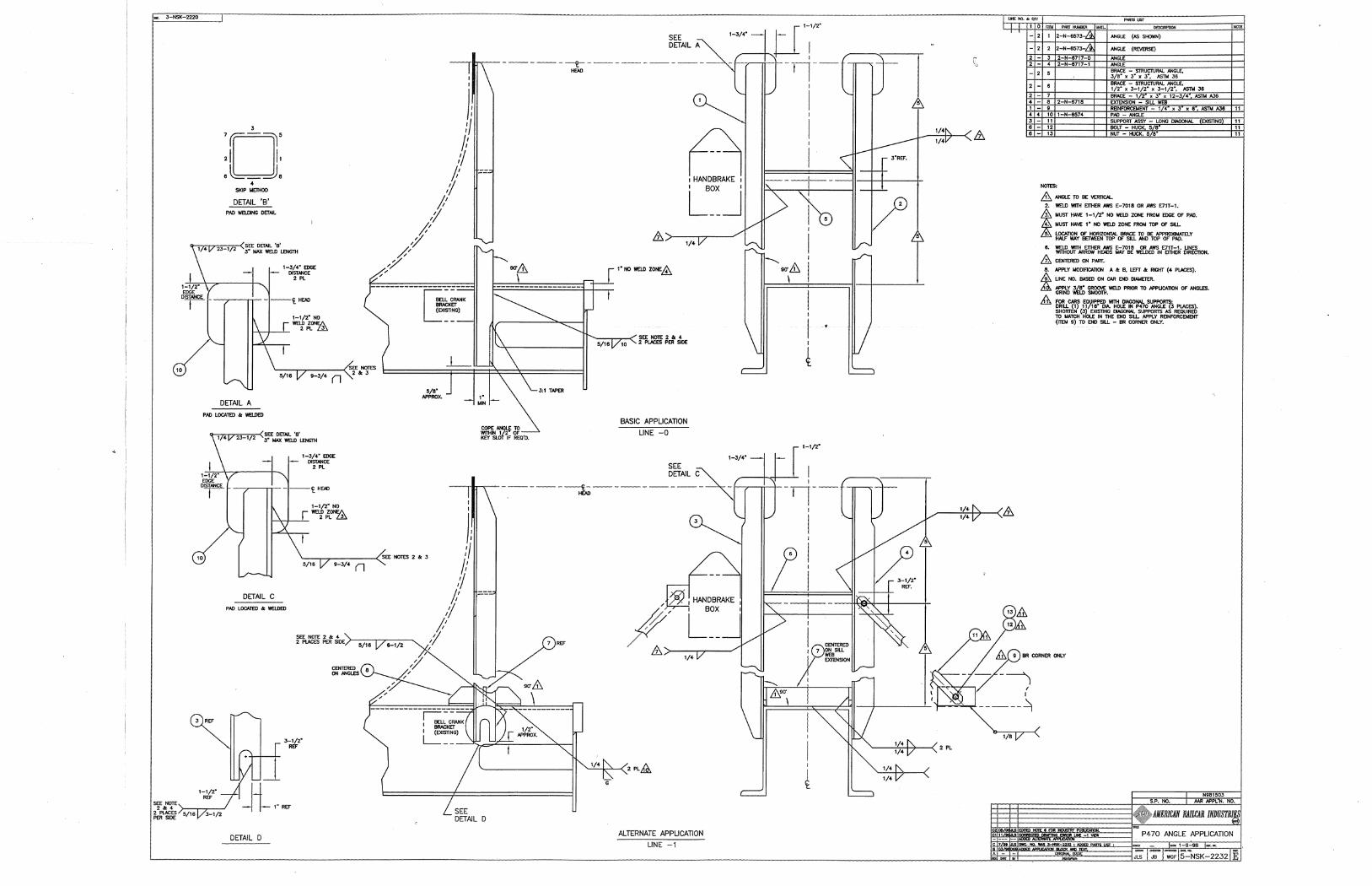
This enhancement is not to be applied to non-carbon steel tank cars, pressure cars, cars with head shields, cars with electric heater coils, sparger cars with head nozzles, or cars modified with head braces. Prior to applying the P470 enhancement, the underframe must be inspected for defects and repaired per the General Section, Appendix A, and Appendix B of this TC-200 maintenance bulletin. Before fabricating any parts, verify all dimensions for each car. All tank welding must be performed by AAR tank car certified welders, and personnel properly trained in the application of a P470 angle retrofit must perform all other welding. REFERENCE MATERIAL: The procedure is directly parallel to ARI Engineering project P470. ARI drawing number 2-NSK-2232 shows the application of the angle retrofit per the written instructions below. The AAR approval number for this procedure is N981503A. INSTRUCTIONS: Standard P470 Application Note: The Standard P470 application is for cars without end sill struts and only partial
coupler key slot interference. A. Verify that car design is an ACF 200 underframe. If car is equipped with end sill
support struts and/or it appears that the angles will have complete interference with the coupler key slot (normally on tanks with 119-1/8" diameter heads), then proceed to the next section of instructions titled, “Alternate P470 Application”.
B. All welding should be performed using AWS E-7018 electrodes or E71T-1 wire
or equivalent.
THIS PROCEDURE MAY BE USED ONLY ON ACF BUILT TANK CARS WITH STUB SILL STYLE 200 UNDERFRAMES AND SOLELY AT THE DISCRETION OF THE CAR OWNER
ACF MAINTENANCE BULLETIN BULLETIN: TC-200 ACF STUB SILL STYLE 200 REVISION: A UNDERFRAME ENHANCEMENT ISSUED: 5-5-06 SHEET: C-2 of 10
C. Remove the crossover end handrail and the tank head attachment bracket. D. Remove a section of jacket and insulation (if required) to access the center of the
tank head. E. Locate the position of the tank pads per drawing 5-NSK-2232 as follows:
1. Locate the horizontal centerline of the tank head. 2. Locate the side of the sill on the tank head. Mark the location of the sill
web on the tank head. 3. Measure 1-3/4" toward the center of the head from the line previously
marked on the tank head in Step E.2 and mark a vertical line. This line will locate the inside edge of the pad.
4. Measure 1-1/2" up from the horizontal centerline marked on the tank head
in Step E.1 and mark a horizontal line. This line will locate the top edge of the pad.
F. Fabricate the four (4) tank pads using 3/8" thick ASTM A-36 material per
drawing 1-N-6574. The pads should be 6-1/2" long X 6-1/2" wide and have a 1-1/2" radius on the corners.
G. Apply the pads to the tank head per drawing 5-NSK-2232 as follows:
1. The inside vertical edge of the pad should be located at the mark made in
Step E.3. 2. The top horizontal edge of the pad should be located at the mark made in
Step E.4. 3. Apply the pads to the tank head with a 1/4" fillet weld.
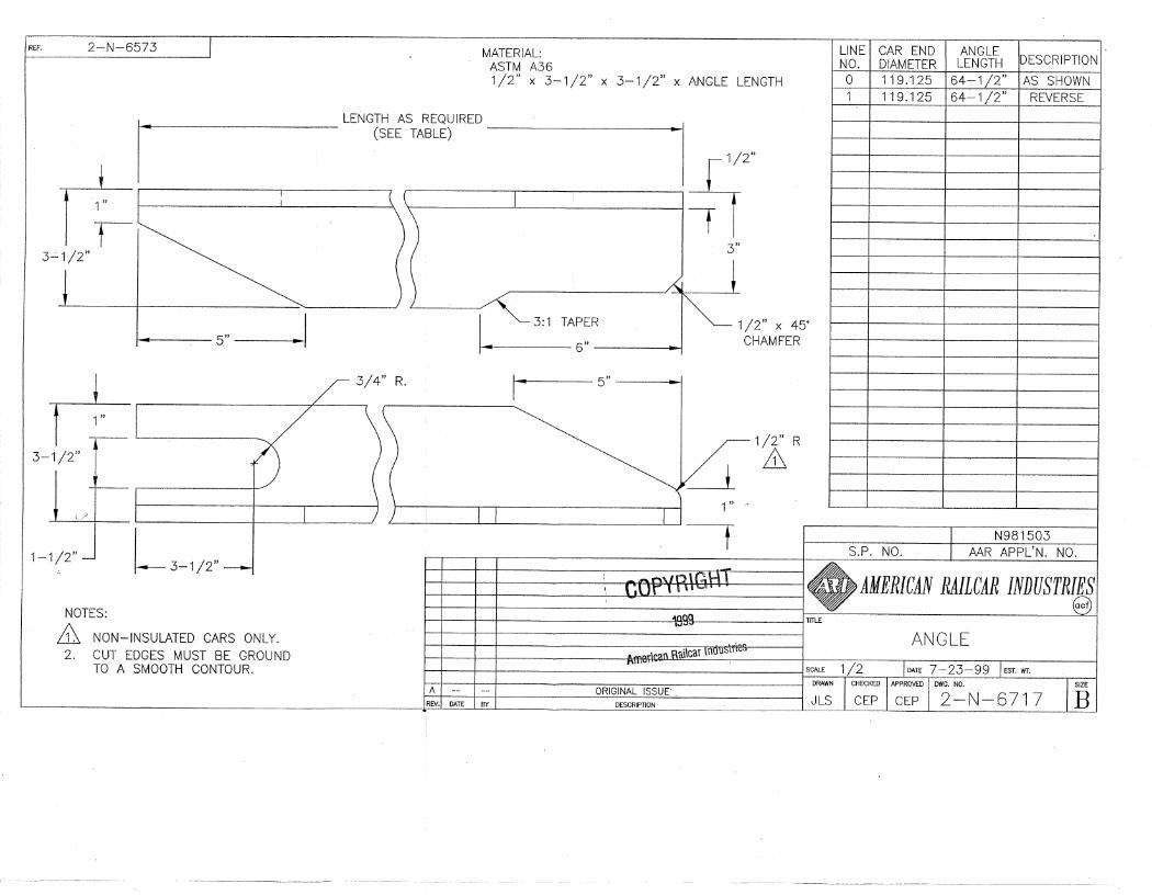
H. Fabricate the angles and apply per 5-NSK-2232 as follows:
1. Fabricate four (4) angles from 3" X 3" X 3/8" ASTM A-36 structural
angle. The length will be determined from the drawing by the head diameter. Two (2) should be as shown per 2-N-6573 and two (2) should be opposite. Also, reference the “P470 Angle Length Information Chart”
THIS PROCEDURE MAY BE USED ONLY ON ACF BUILT TANK CARS WITH STUB SILL STYLE 200 UNDERFRAMES AND SOLELY AT THE DISCRETION OF THE CAR OWNER
ACF MAINTENANCE BULLETIN BULLETIN: TC-200 ACF STUB SILL STYLE 200 REVISION: A UNDERFRAME ENHANCEMENT ISSUED: 5-5-06 SHEET: C-3 of 10
located at the end of this Appendix. 2. From the top of the pads welded to the tank, measure down 1-1/2" and
mark a horizontal line. This line will represent the top termination of the angle.
3. Measure 1-3/4" from the inside edge of the pad and mark. This line will
represent the inside edge of the angle. 4. Place the angles on each side of the sill and align so that the top and side
of the angle lies in the area previously mapped-out in Steps H.2 and H.3 above.
5. Depending on the configuration of each individual car, these items may
need to be addressed. a. The bottom of the angle may require coping if there is partial
interference with the coupler key slot. b. On the B-end of the car the bell crank bracket may need to be
modified. c. Brake lines may need to be moved slightly. d. Brake reservoir brackets may need to be relocated.
6. Apply the angles with a 5/16" fillet weld.
a. Weld the angle to the pad at the top and the two sides. Note the 1-1/2" no-weld zone at the bottom edge of the pad.
b. Weld the angle to the sill using a 5/16" fillet to the sides of the
angle to the sill web. There is a 1" no weld zone from the top edge of the sill web.
c. There must be a total of 20" of weld length at each location on the
sill web. I. Apply a horizontal brace between the vertical angles per drawing 5-NSK-2232 as
follows:
THIS PROCEDURE MAY BE USED ONLY ON ACF BUILT TANK CARS WITH STUB SILL STYLE 200 UNDERFRAMES AND SOLELY AT THE DISCRETION OF THE CAR OWNER
ACF MAINTENANCE BULLETIN BULLETIN: TC-200 ACF STUB SILL STYLE 200 REVISION: A UNDERFRAME ENHANCEMENT ISSUED: 5-5-06 SHEET: C-4 of 10
1. From the top of the sill web measure half the distance to the top of the vertical angles and mark. This line represents where the horizontal brace will be located.
2. Measure the distance between each angle to find the length required for
the horizontal brace. 3. Fabricate the horizontal braces using the same material as the vertical
braces (3" X 3" X 3/8" ASTM A-36 structural angle). 4. Apply the horizontal brace with 1/4" fillet welds so that the legs extend
down and outboard. J. Locate, fabricate, and apply a jacket cover hood if required as follows:
1. Fabricate the jacket flashing using 1/8" jacket material and apply with 1/8"
welds. Flashing should have 1” minimum clearance at the angles. 2. Apply insulation as required inside the cover hood of the same type as
previously removed. 3. Fabricate a bottom cover to seal off the base of the jacket cover hood to
prevent insulation from falling out. 4. Do not weld the jacket or bottom cover to any part of the angles.
K. Reapply end crossover handrail as required per 49 CFR 231 – Railroad Safety Appliance Standards.
L. Ensure the P470 enhancement was applied to both ends of the car. M. Complete an AAR Form R-1 to document the application of the P470
enhancement. N. Update the UMLER stub sill designation to ACF 270.
THIS PROCEDURE MAY BE USED ONLY ON ACF BUILT TANK CARS WITH STUB SILL STYLE 200 UNDERFRAMES AND SOLELY AT THE DISCRETION OF THE CAR OWNER
ACF MAINTENANCE BULLETIN BULLETIN: TC-200 ACF STUB SILL STYLE 200 REVISION: A UNDERFRAME ENHANCEMENT ISSUED: 5-5-06 SHEET: C-5 of 10
INSTRUCTIONS: Alternate P470 Application Note: The Alternate P470 application applies to cars with complete coupler key slot
interference or end sill struts. A. Check to ensure car design has an ACF 200 underframe. Car should be either
equipped with end sill support struts or have angles with complete interference with the coupler key slot (this normally occurs on tanks with 119-1/8" diameter heads), or both. Use only the applicable parts of the following instructions.
B. All welding should be performed using AWS E-7018 electrodes or E71T-1 wire
or equivalent. C. Remove the crossover grating, end handrail, and the tank head attachment
bracket. D. Remove end sill reinforcements if required as follows:
1. Ensure the end arrangements are properly braced. 2. Remove both end sill struts on the A-end of the car. 3. Remove only the right side strut on the B-end of the car (normally the left
side strut is attached to the hand brake).
4. Remove end grating. 5. Cut the end sill reinforcement angle loose at the center sill to allow room
for the angles. Remove the section that is across the top of the sill. E. Locate the position of the tank pads per drawing 5-NSK-2232-1 as follows:
1. Locate the horizontal centerline of the tank head. 2. Locate the side of the sill on the tank head. Mark the location of the sill
web on the tank head. 3. Measure 1-3/4" toward the center of the head from the line previously
marked on the tank head in Step E.2 above and mark a vertical line. This line will locate the inside edge of the pad.
THIS PROCEDURE MAY BE USED ONLY ON ACF BUILT TANK CARS WITH STUB SILL STYLE 200 UNDERFRAMES AND SOLELY AT THE DISCRETION OF THE CAR OWNER
ACF MAINTENANCE BULLETIN BULLETIN: TC-200 ACF STUB SILL STYLE 200 REVISION: A UNDERFRAME ENHANCEMENT ISSUED: 5-5-06 SHEET: C-6 of 10
4. Measure 1-1/2" up from the horizontal centerline marked on the tank head
in Step E.1 and mark a horizontal line. This line will locate the top edge of the pad.
F. Fabricate the four (4) tank pads using 3/8" thick ASTM A-36 material per
drawing 1-N-6574. The pads should be 6-1/2" long X 6-1/2" wide and have a 1-1/2" radius on the corners.
G. Apply the pads to the tank head per drawing 5-NSK-2232-1 as follows:
1. The inside vertical edge of the pad should be located at the mark made in
Step E.3. 2. The top horizontal edge of the pad should be located at the mark made in
Step E.4. 3. Apply the pads to the tank head with a 1/4" fillet weld.
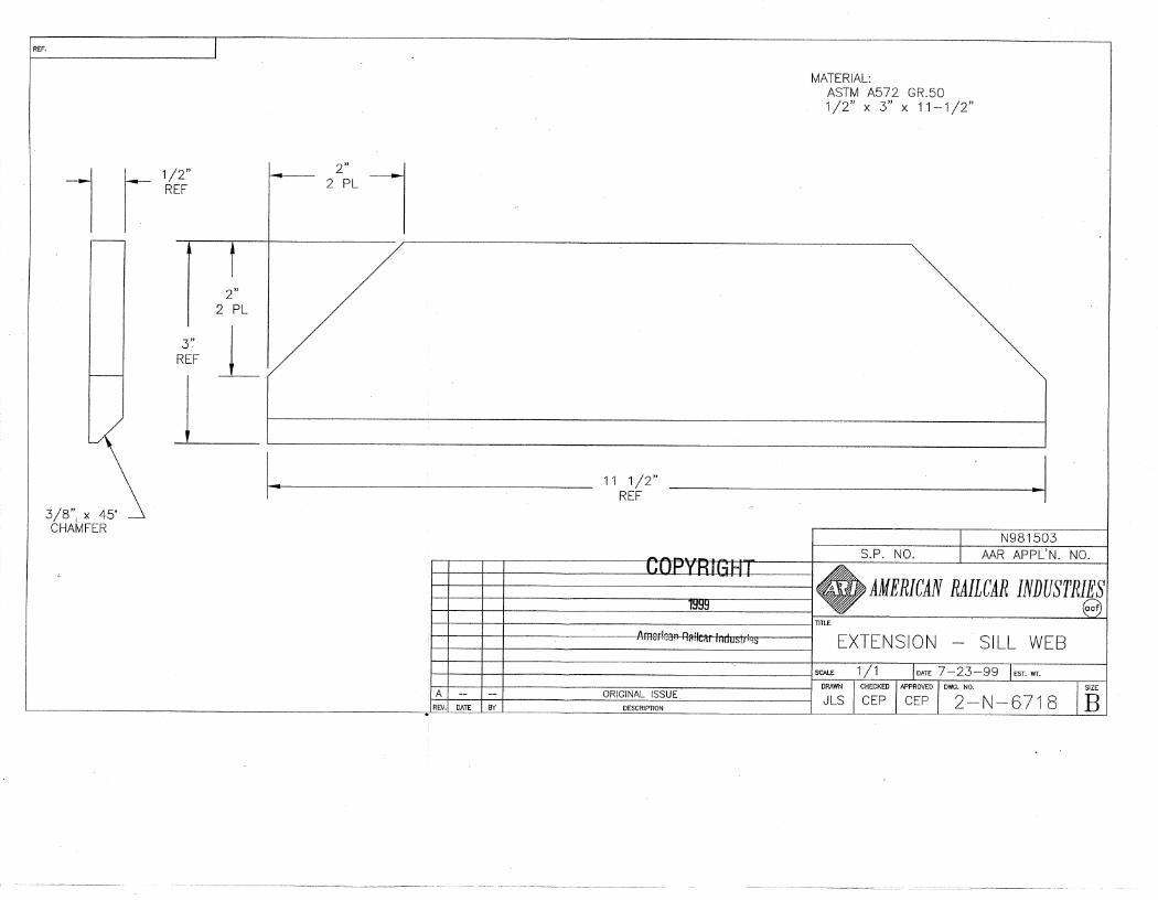
H. Apply sill web extensions and sill cross brace per 5-NSK-2232-1 as follows:
1. Mark where the angles will be located on the sill webs. Use this mark to locate the sill web extensions.
2. Fabricate four (4) sill web extensions per 2-N-6718. 3. Bevel the bottom 3/8" x 45° for groove welding on the outside of the sill. 4. Apply a 1/4" fillet weld on the inside of the sill and a 3/8" groove weld on
the outside of the sill. Grind 3/8" groove weld flush. 5. The sill web extension must be located directly over the existing sill web
and centered with location of the angles. 6. Fabricate two (2) sill cross braces 1/2" x 3" x 12-3/4" long using ASTM
A-36 material. 7. Apply the sill cross braces across top sill flange and centered between sill
web extensions with 1/4" fillet welds. I. Fabricate the angles and apply per 5-NSK-2232-1 as follows:
THIS PROCEDURE MAY BE USED ONLY ON ACF BUILT TANK CARS WITH STUB SILL STYLE 200 UNDERFRAMES AND SOLELY AT THE DISCRETION OF THE CAR OWNER
ACF MAINTENANCE BULLETIN BULLETIN: TC-200 ACF STUB SILL STYLE 200 REVISION: A UNDERFRAME ENHANCEMENT ISSUED: 5-5-06 SHEET: C-7 of 10
1. Fabricate four (4) angles from 3-1/2" X 3-1/2" X 1/2" ASTM A-36
structural angle. The length will be determined from the drawing by the head diameter. Two (2) should be as shown per 2-N-6717 and two (2) should be opposite per 2-N-6717-1. Also, reference the “P470 Angle Length Information Chart” located at the end of this Appendix.
2. From the top of the pads welded to the tank, measure down 1-1/2" and
mark a horizontal line. This line will represent the top termination of the angle.
3. Measure 1-3/4" from the inside edge of the pad and mark. This line will
represent the inside edge of the angle. 4. Place the angles on each side of the sill and align so that the top and side
of the angle lies in the area previously mapped-out in Steps I.2 and I.3 above.
5. Depending on the configuration of each individual car, these items may
need to be addressed. a. On the B-end of the car the bell crank bracket may need to be
modified. b. Brake lines may need to be moved slightly. c. Brake reservoir brackets may need to be relocated.
6. Apply the angles with a 5/16" fillet weld.
a. Weld the angle to the pad at the top and the two sides. Note the 1-1/2" no-weld zone at the bottom edge of the pad.
b. Weld the angle to the sill web and sill web extension using a 5/16"
fillet along the sides of the angle and the angle slot. c. There must be a total of 20" of weld length at each location on the
sill web and sill web extensions. J. Apply a horizontal brace between the vertical angles per drawing 5-NSK-2232-1
as follows:
THIS PROCEDURE MAY BE USED ONLY ON ACF BUILT TANK CARS WITH STUB SILL STYLE 200 UNDERFRAMES AND SOLELY AT THE DISCRETION OF THE CAR OWNER
ACF MAINTENANCE BULLETIN BULLETIN: TC-200 ACF STUB SILL STYLE 200 REVISION: A UNDERFRAME ENHANCEMENT ISSUED: 5-5-06 SHEET: C-8 of 10
1. From the top of the sill web measure half the distance to the top of the
vertical angle and mark. This line represents where the horizontal brace will be located.
2. Measure the distance between each angle to find the length required for
the horizontal brace. 3. Fabricate the horizontal brace using the same material as the vertical
angles (3-1/2" X 3-1/2" X 1/2" ASTM A-36 structural angle). 4. Apply the horizontal brace with 1/4" fillet welds so that the legs extend
down and outboard. K. Reapply struts and end sill arrangement as necessary per 5-NSK-2232-1 as
follows:
1. Butt end sill reinforcement angle into the angle or sill along side angle and weld with 1/4" fillet welds.
2. Locate the 11/16" diameter holes for attaching the struts to the angles at
the angle brace. Hole should be drilled, or burnt and reamed or ground. Hole must not be notched or excessively oversized.
3. Shorten the struts as required to match the existing hole in the end sill and
the hole in the angle. Shorten struts by removing a section from the middle of the struts and welding together with 100% penetration using a chill ring.
4. Weld a 3" x 6" x 1/4" thick A-36 pad with an 11/16" diameter hole to the
existing end sill angle to reinforce the hole for the BR strut only. 5. Apply struts using appropriate 5/8” fasteners to the end sill and the angles. 6. Reapply end grating.
L. Reapply end crossover handrail as required per 49 CFR 231 – Railroad Safety Appliance Standards.
M. Ensure the P470 enhancement was applied to both ends of the car.
THIS PROCEDURE MAY BE USED ONLY ON ACF BUILT TANK CARS WITH STUB SILL STYLE 200 UNDERFRAMES AND SOLELY AT THE DISCRETION OF THE CAR OWNER
ACF MAINTENANCE BULLETIN BULLETIN: TC-200 ACF STUB SILL STYLE 200 REVISION: A UNDERFRAME ENHANCEMENT ISSUED: 5-5-06 SHEET: C-9 of 10
N. Complete an AAR Form R-1 to document the application of the P470 enhancement.
O. Update the UMLER stub sill designation to ACF 270.
THIS PROCEDURE MAY BE USED ONLY ON ACF BUILT TANK CARS WITH STUB SILL STYLE 200 UNDERFRAMES AND SOLELY AT THE DISCRETION OF THE CAR OWNER

ACF MAINTENANCE BULLETIN BULLETIN: TC-200 ACF STUB SILL STYLE 200 REVISION: A UNDERFRAME ENHANCEMENT ISSUED: 5-5-06 SHEET: C-10 of 10
P470 Angle Length Information Chart
Tank Head Inside
Diameter
Coupler Type
Center Line of Tank head
Angle Length
119.125” E 60.25” 64.500” 119.125” F 60.25” 71.750”
114.795” E 58.085” 62.335” 114.795” F 58.085” 69.500” 110.250” E or F 55.813” 67.313”
106” E or F 53.6875” 65.1875” 103.25” E or F 52.3125” 63.8125”
98” E or F 49.6875” 61.1875” 95” E or F 48.1875” 59.6875”
87.125” E or F 44.25” 55.750”
THIS PROCEDURE MAY BE USED ONLY ON ACF BUILT TANK CARS WITH STUB SILL STYLE 200 UNDERFRAMES AND SOLELY AT THE DISCRETION OF THE CAR OWNER