tc-200 two channel temperature controlemanuals.nordson.com/finishing/files/cont-liq/108229a.pdf ·...
TRANSCRIPT

TC-200 Two Channel Temperature Control
Part 108 229A
NORDSON CORPORATION l AMHERST, OHIO l USA
Nordson Corporation welcomes requests for information, comments and inquiries about its products.
Address all correspondence to
Nordson Corporation 11475 Lakefield Drive
Duluth, GA 30136
Notice
This is a No&on Corporation publication which is protected by copyright. No part of this document may be photocopied, reproduced, or translated to another language without the prior written consent of Nordson
Corporation. The information contained in this publication is subject to change without notice.
Trademarks
AquaGuard, Blue Box, Control Coat, Equi=Bead, FloMelt, FoamMelt, FoamMix, Helix, Hot Shot, Hot Stitch, Meltex, MicroSet, MultiScan, Nordson, the Nordson logo, OmniScan, Porous Coat, Posi-Stop, RBX, Sure-Bond,
UniScan, UpTime, and Versa-Spray are registered trademarks of Nordson Corporation.
BetterBooksM, CF, Controlled Fiberization, Easy-Screen, Fibermelt, Flo-Tracker, PrintGuard, and Package of Values are trademarks of Nordson Corporation.
Manual 46-180 108 229A Issued 1 l/91
Q Igel tuofdm Cofpofaticm All Riits Reseived

TC-200 Two Channel Temperature Control Manual 46-l 80 Page 0- 1
Table of Contents
Section 1 Safety Summary
1.1. Introduction ...................................................................................................................................... l-l 1.2. Explanation of Terms and Symbols ............................................................................................... l-l 1.3. Safety During Installation ............................................................................................................. l-l
1.3.1. Electrical .......................................................................................................................... l-l 1.3.2. Pneumatic ......................................................................................................................... l-l
1.4. Safety During Operation ................................................................................................................ l-l 1.5. Safety During Servicing ................................................................................................................. l-2 1.6. Safety When Using Hot Melt Adhesives and Solvents ............................................................... l-3
1.6.1. Hot Melt Adhesives ......................................................................................................... l-3 1.6.2. Heating Solvents ............................................................................................................. l-3
Section 2 Equipment Familiarization
2.1. Introduction ...................................................................................................................................... 2-l 2.2. TC-200 Modes .................................................................................................................................. 2-2
2.2.1. Operating Modes ............................................................................................................. 2-2 2.2.2. Display Modes .................................................................................................................. 2-2
2.3. User Interface .................................................................................................................................. 2-2 2.3.1. Display .............................................................................................................................. 2-2 2.3.2. LEDs ................................................................................................................................. 2-2 2.3.3. Operator Panel ................................................................................................................ 2-3
2.4. Supervisor Lockout ......................................................................................................................... 2-4
Section 3 Installation
3.1. Introduction ...................................................................................................................................... 3-1 3.2. Inspection ......................................................................................................................................... 3-l 3.3. Safety Precautions .......................................................................................................................... 3-l 3.4. Opening the TC-200 ........................................................................................................................ 3-2 3.5. Installing Shunt Jumpers .............................................................................................................. 3-5
3.5.1. Celsius Temperature Display ........................................................................................ 3-5 3.5.2. Supervisor Lockout ......................................................................................................... 3-6
Publication No. 108 229A 0 Nordson Corporation 1991 All Rights Reserved
Issued 1 I/91
Manual 46-l 80 Page O-2
TC-200 Two Channel Temperature Control
Section 4 Operating Instructions
4.1. Start Up ............................................................................................................................................ 4-l 4.2. Setting Temperature Values .......................................................................................................... 4-l
4.2.1. Settinging the Standby Temperature ........................................................................... 4-2 4.2.2. Setting Sleep Mode ......................................................................................................... 4-2 4.2.3. Setting the Overtemperature Value ............................................................................. 4-3 4.2.4. Setting Setpoint Temperatures ..................................................................................... 4-4
4.3. Placing the TC-200 in the Standby Mode ..................................................................................... 4-5 4.4. Placing the Unit in Sleep Mode ..................................................................................................... 4-6 4.5. Channel Status Messages .............................................................................................................. 4-6 4.6. Error Messages ................................................................................................................................ 4-7
Section 5 Troubleshooting
5.1. Introduction ...................................................................................................................................... 5-1 5.2. Safety During Troubleshooting ..................................................................................................... 5-l
Section 6 Parts List
6.1. Introduction ...................................................................................................................................... 6-l 6.1.1. Using the Parts List ........................................................................................................ 6-l
Section 7 Technical Data
7.1. TC-200 Temperature Control Specifications ................................................................................ 7-l 7.1.1. Operator Interface ........................................................................................................... 7-l 7.1.2. Electrical Specifications ................................................................................................. 7-l 7.1.3. Dimensions ....................................................................................................................... 7-2 7.1.4. Safety ................................................................................................................................ 7-2 7.15. Operating Environment ................................................................................................. 7-2
Issued 11/91 0 Nordson Corporation 1991 All Rights Reserved
Publication No. 108 229A

TC-200 Two Channel Temperature Control Manual 46-l 80 Page O-3
List of Illustrations
Figure 2.1 - TC-200 Two Channel Temperature Control ................................................................... 2-l Figure 2.2 - TC-200 User Interface ...................................................................................................... 2-3 Figure 3.1 - Removing Screws to Open the TC-200 ........................................................................... 3-2 Figure 3.2 - Opening the TC-200 .......................................................................................................... 3-3 Figure 3.3 - TC-200 Terminal Block Installation ............................................................................... 3-4 Figure 3.4 - Temperature Display Shunt Jumper Installation ......................................................... 3-5 Figure 3.5 - Supervisor Lockout Shunt Jumper Installation ............................................................ 3-6 Figure 4.1 - Start Up Display ................................................................................................................ 4-l Figure 4.2 - Setting Standby Temperature .......................................................................................... 4-2 Figure 4.3 - Setting the Overtemperature Value ................................................................................ 4-3 Figure 4.4 - Setting Setpoint Temperatures ........................................................................................ 4-4 Figure 4.5 - Standby Mode Display and LED Status ......................................................................... 4-5 Figure 4.6 - Low Temperature Display ................................................................................................ 4-6 Figure 4.7 - Display When No Channels Connected .......................................................................... 4-6 Figure 4.8 - Alarm Overtemperature Display ..................................................................................... 4-7 Figure 4.9 - RTD Open Circuit .............................................................................................................. 4-7 Figure 4.10 - RTD Short Circuit ........................................................................................................... 4-7 Figure 5.1 - TC-200 Electrical Wiring Diagram ................................................................................. 5-3 Figure 5.2 - TC-200 Electrical Schematic.. .......................................................................................... 5-4
List of Tables
Table 4.1 - Factory Default Temperature Values ................................................................................ 4-1 Table 5.1 - Troubleshooting Guide ........................................................................................................ 5-l Table 6.1 - TC-200 Parts List ................................................................................................................ 6-1
Publication No. 108 229A 0 Nordson Corporation 1991 All Rights Reserved
Issued 11/91


TC-200 Two Channel Temperature Control Manual 46-180 Page l-l
Section 1 Safety Summary
1.1. Introduction
This section provides safety guidelines for use of Nordson@ equipment. These guidelines apply to all operations and service personnel working with the application equipment and its com- ponents. Safety warnings are repeated throughout this manual, along with specific warnings and cautions not included in this sec- tion. These safety guidelines cover installation, operation and servicing.
A Warning: Failure to follow these recom- mendations can result in personal in- jury from burns or electrocution and/or cause equipment and property damage.
1.2. Explanation of ‘Ikrms and Symbols
The following safety symbols and signal words d. Only fuses of the correct type, voltage rating are used throughout this publication, alerting and current rating should be used. Refer to the the reader to personal safety hazards, or iden- application equipment parts list for fuse recom- tifying conditions that can result in equipment mendations. Using incorrect or non-recom- or property damage. mended fuses can present a fire hazard.
A Warning: General Warning. Failure to observe can result in personal injury or death.
A t Warning: Risk of electrical shock. Failure to observe can result in personal injury or death.
A Caution: General Caution. Failure to observe can result in minor personal in- jury or damage to property.
Note: Important information. Failure to observe can result in equipment damage.
1.3. Safety During InstaIIation
1.3.1. Electrical
a. A protective electrical ground connection to a reliable earth ground is essential for safe opera- tion. Without a reliable ground, all accessible conductive components (including knobs and controls that appear insulated) can render an electric shock.
b. A disconnect switch with lockout capability must be provided between the power source and the equipment.
c. The power supply’s wire gauge and insula- tion must be sufficient to meet application equip- ment temperature and power requirements.
1.3.2. Pneumatic
It is recommended that a three-way, manual valve with lockout capability, be installed in the air supply line to Nordson equipment. This valve makes it possible to relieve air pressure and lock out the pneumatic system before under- taking maintenance or repairs.
1.4. Safety During Operation
Do Not operate Nordson application equipment under the following conditions:
a. At pressures higher than the rated maxi- mum working pressure of any system component.
b. Near volatile or otherwise explosive gases or materials.
Publication No. 136 899A 0 Nordson Corporation 1991 All Rights Reserved
Issued 1 l/91

Manual 46-l 80 Page 1-2
TC-200 Two Channel Temperature Control
1.4. Safety During Operation (Continued)
c. Without equipment covers, panels and safety guards properly installed.
d. At atmospheric temperatures below 20” F (-6” C) or above 120” F (50” 0.
e. With hoses enclosed in any material imped- ing heat dissipation, including electrical con- duit, insulation of any type or tight metal covers
f. With large areas of hose contacting a cold floor, cold supports or other such surfaces. Cold points along the hose restrict the flow of ad- hesive inside the hose and can create potential problems during operation.
g. In drafty areas with the applicator guns un- shielded from the draft. Rapid heat dissipation due to air movement across the guns can cause operational problems.
h. If applicator handguns are used, with the handguns left unlocked while the guns are unat- tended.
In addition:
i. Use only the metal base when attempting to lift or move an applicator. Do Not use equiment covers, doors, panels or hose connectors as braces or grips.
j. Never use application equipment as a lad- der or stepping stool.
k. Route all hoses such that damage from kink- ing, abrasion and other physical damage is prevented. Do Not allow a hose to be installed with a bend radius of less than 6 in. (15.2 cm).
1. Never point an applicator handgun at your- self or anyone else.
1.5. Safety During Servicing
a. Do Not perform internal service or adjust- ment on any equipment unless another person
capable of rendering first aid and resuscitation is present.
b. Only qualified personnel should service the application equipment.
c. Avoid personal injury by never touching ex- posed connections and components while electri- cal power is on. Dangerous voltages exist at several points in the equipment.
d. Disconnect, lock out and tag external electri- cal power before removing protective panels or replacing electrical components.
e. Remove all jewelry (rings, watches, etc.) before servicing equipment.
f. If possible, stand on a rubber mat when ser- vicing applicator equipment or its components. Do Not work on equipment if standing water is present. Avoid working in a high-humidity atmosphere. Cover exposed terminals and work areas with rubber sheeting to avoid accidental contact while the electrical power is on.
g. Always wear safety goggles (ANSI 287.1- 1989 or equal), protective gloves (Nordson P/N 902 514 or equivalent), and long-sleeve protec- tive clothing to prevent injury from hot applicator parts, splashed hot melt adhesive and hot gun surfaces.
h. To prevent serious injury from molten ad- hesive under pressure, always relieve system hydraulic pressure (by triggering the gun, for ex- ample) before opening any hydraulic fitting or connection.
i. Never use an open torch, drill, or broach when cleaning a nozzle.
j. Never operate equipment with a known system leak.
-
Issued 1 l/91 0 Nordson Corporation 1991 All Rights Reserved
Publication No. 136 899A

TC-200 Two Channel Temperature Control Manual 46-180 Page l-3
1.6. Safety When Using Hot Melt Adhesives and Solvents
1.6.1. Hot Melt Adhesives
Use extreme care when working with molten hot melt adhesives. Molten hot melt adhesives solidify rapidly at high temperatures, present- ing a hazard. Severe burns can occur if the mol- ten materials come in contact with the skin. Even when first solidified, they are still hot.
a. Always wear protective clothing and eye protection when handling molten material or working near equipment containing hot melt adhesives under pressure.
b. If molten material comes in contact with the skin:
l Do Not try to remove molten material from the skin.
l Immediately immerse the affected area in cold, clean water. Keep the affected areas immersed until the material has cooled.
l Do Not try to remove the cooled material from the skin.
l Cover the affected area with a clean, wet compress.
l In cases of severe burns, look for signs of shock. If shock is suspected, have the patient lie down, use a blanket to preserve body heat and elevate the feet several inches.
l Call a physician immediately.
1.6.2. Heating Solvents
a. Do Not use an open flame or uncontrolled heating device to heat solvents (for example, a small pan on an unregulated hot plate).
b. Avoid fire hazard by using a controlled heat- ing device to heat solvents (for example, a small deep fat fryer or thermostatically-controlled hot plate).
c. Do Not use paint-type solvents under any circumstances! These solvents are
volatile, presenting fire and/or toxic-vapor hazards, even at room temperature.
d. Always be sure the work area is adequately ventilated. Avoid prolonged or repeated breath- ing of solvent vapors.
e. Never clean any aluminum component or flush any system using halogenated hydrocar- bon solvents. Halogenated hydrocarbon solvents are dangerous when used to clean aluminum components in a pressurized fluid system. No available stabilizers prevent halogenated hydrocarbon solvents from reacting under all conditions with the applicator’s aluminum components. Use Type R (P/N 270 755) solvents or contact your solvent or hot melt supplier for a non-halogenated hydrocarbon solvent for cleaning and flushing.
Halogenated fluids include the following sol- vents:
Fluorinated Solvents:
l Dichlorofluoromethane
l Trichlorofluoromethane
Chlorinated Solvents:
l Carbon Tetrachloride
l Chloroform
l Dichloromethane
l Ethlylene Dichloride
l Methylene Chloride
l Monochlorobenzene
l Monochlorotoluene
l Orthodichlorobenzene
l Perchloroethylene
l Trichloroethylene
Brominated Solvents:
l Ethylene Dibromide
l Methyl Bromide
l Methylene Chlorobromide
Publication No. 136 899A 0 Nordson Corporation 1991 All Rights Reserved
Issued 1 l/91
Manual 46-l 80 Page l-4
TC-200 Two Channel Temperature Control
1.6. Safety When Using Hot Melt Adhesives and Solvents (Continued)
Iodinated Solvents:
l Ethyl Iodide
l Methyl Iodide
l N-butyl Iodide
l Propyl Iodide
-
Issued II/91 0 Nordson Corporation 1991 All Rights Reserved
Publication No. 136 899A

TC-200 Two Channel Temperature Control
Section 2 Equipment Familiarization
Manual 46-l 80 Page 2-l
2.1. Introduction l Digital temperature setpoint
The Nordson@ TC-200 Two Channel Tempera- ture Control (TC-200) provides complete temperature control for Nordson RTD-style hoses and guns. This PI-type control provides two control loops, one for the hose and one for the gun.
. Supervisor keypad lockout
l Safety overtemperature protection
l Adjustable overtemperature setpoint
l Remote fault relay
l Remote unit ready signal
Other advanced features include: l Temperature standby
l Digital temperature display l Temperature sleep
Figure 2.1 - TC-200 Two Channel Temperature Control
Publication No. 108 229A 0 Nordson Corporation 1991 All Rights Reserved
Issued 1 l/91

Manual 46-l 80 Page 2-2
TC-200 Two Channel Temperature Control
2.2. TC-200 Modes
2.2.1. Operating Modes
The three operating modes are Run, Standby, and Sleep.
Run Mode - The channels are connected and operating within the selected temperature set- points.
mode is on. If Scan display mode is on, the display sequentially shows each channel and the setpoint temperature of the heater. This sequential display continues as long as the unit is in Scan display mode.
Standby Setpoint - Press and hold the Standby switch until the Standby Active LED comes on. Press and hold the Temperature Set switch. The display shows the Standby setpoint.
Standby Mode - The TC-200 reduces the temperature of the heating channels to the standby temperature setpoint. This maintains the material well below application tempera- ture, but above its melting point. Holding the material at standby temperature reduces char- ring and degrading during temporary interrup- tions to system operation. When Standby mode is exited, the system returns to the original temperature setpoints.
Alarm Setpoint - Press and hold the Alarm switch. The display shows the Alarm setpoint.
Alarm - The display shows the channel with the alarm condition, plus one of the error messages: “E-o”, “Emro”, or “E-rs”.
2.3. User Interface
2.3.1. Display
Sleep Mode - This mode enables remote turn off of power to the heating channels. Hot melt material can then cool to room temperature.
2.2.2. Display Modes
There are four display modes:
The display consists of five 7-segment LEDs (Figure 2.2). The display can show tempera- tures in Fahrenheit or Celsius. The default dis- play is Fahrenheit. Celsius temperature will show if a shunt jumper is connected to SW7 on the printed circuit board. Refer to paragraph 3.5.1. in Section 3 for installation details.
l Scan 2.3.2. LEDs
l Hold There are five LEDs.
l Setpoint
l Alarm
Scan - This is the display mode that the TC-200 is in at start up. The unit continuously scans through the channels. The display sequentially shows each channel and its actual temperature.
Standby - The LED is on when the user selects the Standby mode and is setting the standby temperature. The LED is off when the TC-200 is in the run mode.
Hold - The display shows one channel and the actual temperature of that channel. By pressing then releasing the up or down switches, the user can display the other channel.
Scan Mode Active - The LED is on when the dis- play is scanning through the channels. The LED is off when the display is in the Hold mode (showing information for only one channel).
Setpoint - There are three setpoints which can be displayed.
Set Temperature - This LED is on when the user is changing or viewing the channel set- point. The LED is off when the TC-200 is in the run mode.
l Temperature Setpoint - Press and hold the Temperature Set switch. The display shows one channel and its setpoint if Hold display
Wait - This LED is on at start up or during Standby mode until all channels reach the temperature band (+/- 10” F from the setpoint).
Issued 11/91 0 Nordson Corporation 1991 All Rights Reserved
Publication No. 108 229A

TC-200 Two Channel Temperature Control Manual 46-l 80 Page 2-3
2.3. User Interface (Continued)
Alarm - The LED is on when any of the follow- ing four conditions occurs:
l A channel’s actual temperature is greater than the alarm temperature setpoint.
l There is an open RTD sensor for any channel.
l There is a shorted RTD sensor for any channel.
l While viewing or setting Alarm temperature setpoint.
2.3.3. Operator Panel
There are six switches on the operator panel.
Standby Switch - Pressing and releasing this switch turns Standby mode on or off.
CHANNEL COUNT
e STANDBY ACTIVE LED -.
.
STANDBY SWITCH (ENABLE/DISABLE)
SCAN MODE ACTIVE LED
SCAN SWITCH (ENABLE/DISABLE)
TEMP SET ACTIVE LED ---
TEMPERATURE SET SWITCH
UNIT ON/OFF ROCKER SWITCH
0 Nordsotr -
/
-
_ -TC-200- CHANNEL TEMPERATURE
I
w-- STANDBY WAIT
-
- a$&
SCAN ALARM SET
Figure 2.2 - TC-200 User interface
- CHANNEL TEMPERATURE ACTUAL OR SETPOINT OR ALARM SETPOINT OR STANDBY SETPOINT
-DEGREES FAHRENHEIT OR
DEGREES CENTIGRADE
- ‘WAIT’ LED (UNIT HEATHG)
--‘WAIT’ SYMBOL (NO SWITCH)
-ALARM LED (.RED’)
-ALARM SET SWITCH
- UP SWITCH (INCREMENTI
-DOWN SWITCH (DECREMENT)
- FUSES
Publication No. 108 229A 0 Nordson Corporation 1991 All Rights Reserved
Issued 1 l/91

Manual 46-180 Page 2-4
TC-200 Two Channel Temperature Control
2.3. User Interface (Continued)
Scan Switch - Pressing and releasing this switch selects either the Hold display mode (Scan Active LED ofI7 or the Scan display mode (Scan Active LED on).
Temperature Set Switch - Pressing and holding this switch displays the channel temperature setpoint, and lets a user change values with the Up and Down switches.
Alarm Set Switch - Pressing and holding this switch displays the channel overtemperature value, and lets the user change values with the Up and Down switches.
Up Switch - This switch changes the channel number shown in Hold mode to the next higher channel number. The switch also increases temperature setpoint values.
channel number. The switch also decreases temperature setpoint values.
Note: Pressing and releasing either the Up or Down switch increases or decreases the temperature value by one. Pressing and holding either switch chan- ges the value slowly for the first five degrees. Then the value rapidly in- creases or decreases until the user releases the Up or Down switch.
2.4. Supervisor Lockout
The TC-200 comes with the keypad ready to ac- cept input to change the Setpoint, Alarm, and/or Standby temperatures. Enabling Supervisor Lockout prevents the TC-200 from accepting keypad changes to the setpoints. The lockout consists of a shunt jumper connected to SW8 on the printed circuit board. Refer to paragraph 3.5.2. in Section 3 for installation details.
Down Switch - This switch changes the channel number shown in Hold mode to the next lower
Issued 1 l/91 0 Nordson Corporation 1991 All Rights Reserved
Publication No. 108 229A

TC-200 Two Channel Temperature Control
Section 3 Installation
Manual 46-l 80 Page 3-1
3.1. Introduction
This section includes:
l Procedures for inspecting the TC-200
l Safety precautions
l Instructions for opening the unit in order to make electrical connections
l Instructions for installing shunt jumpers for Celsius temperature display and Supervisor Lockout
3.2. Inspection
After unpacking the TC-200, inspect it for dents, scratches, corrosion, or other physical damage. In case of damage, contact your Nordson sales representative before installing the TC-200.
3.3. Safety Precautions
Note: It is urgent that personnel install- ing this equipment first refer to the applicator technical manual. The manual provides important safety, operation, and troubleshooting information used with procedures presented in this manual.
Warning: Even when switched off, the TC-200 and the applicator contain ener- gized components with electrical poten- tials that can cause death. Disconnect and lock out the input power line to the TC-200 and the applicator before open- ing the unit. Also, avoid touching any energized components in the TC-200 or the applicator.
Publication No. 108 229A 0 Nordson Corporation 1991 All Rights Reserved
Issued 1 l/91

Manual 46-180 Page 3-2
TC-200 Two Channel Temperature Control
3.4. Opening the TC-200
a. Push the unit on/off rocker switch to the off position.
A
A * Warning: Even when switched off, the TC-200 and the applicator contain ener- gized components with electrical poten- tials that can cause death. Disconnect and lock out the input power line to the TC-200 and the applicator before open- ing the unit. Also, avoid touching any
b. Loosen and remove the six screws shown in Figure 3.1.
energized components in the TC-200 or the applicator.
Warning: Removing the wrong screws from the unit can result in printed cir- cuit board damage during reassembly. Remove only the six screws specified below.
REMOVE SCREW k---l
REMOVE SCREW -
REMOVE SCREW -
0 w TEY? SLT IYI
- REMOVE SCREW
-REMOVE SCREW
b- NOTE: DO NOT REMOVE THESE 2 SCREWS, WHEN OPENING UNIT.
REMOVE SCREW
Figure 3.1 - Removing Screws to Open the TC-200
Issued 11/91 0 Nordson Corporation 1991 All Rights Reserved
Publication No. 108 229A

Manual 46-180 Page 3-4
TC-200 Two Channel Temperature Control
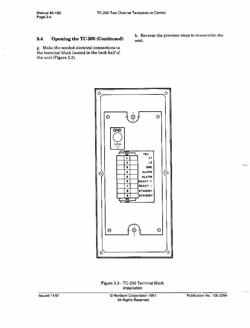
3.4 Opening the TC-200 (Continued) h. Reverse the previous steps to reassemble the unit.
g. Make the needed electrical connections to the terminal block located in the back half of the unit (Figure 3.3).
GND
Q
Figure 3.3 - TC-200 Terminal Block Installation
issued 1 l/91 0 Nordson Corporation 1991 All Rights Reserved
Publication No. 108 229A
TC-200 Two Channel Temperature Control Manual 46-180 Page 3-5
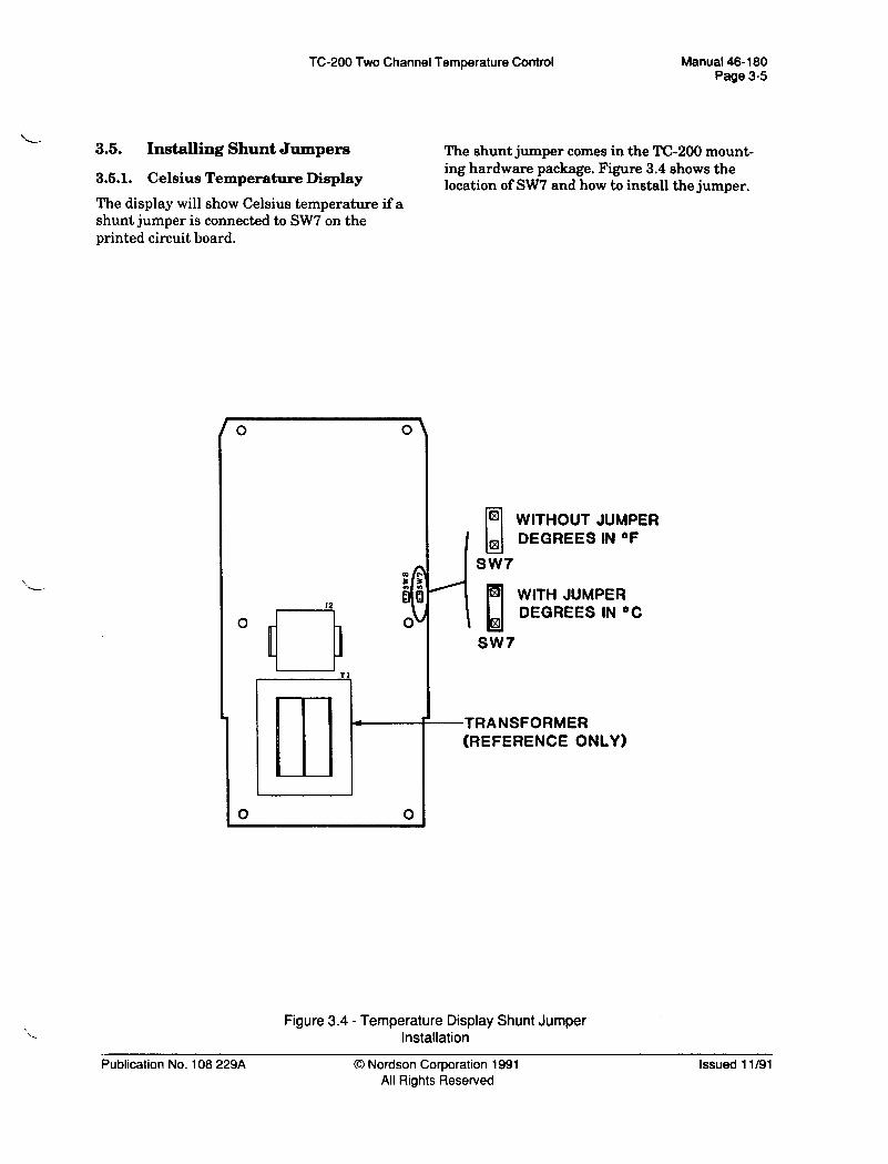
3.5. Installing Shunt Jumpers The shunt jumper comes in the TC-200 mount-
3.5.1. Celsius Temperature Display ing hardware package. Figure 3.4 shows the location of SW7 and how to install the jumper.
The display will show Celsius temperature if a shunt jumper is connected to SW7 on the printed circuit board.
0
m I
I2 xi
.i
( 0
Tl
4
0 0
WITHOUT JUMPER
I
DEGREES IN OF
SW7
WITH JUMPER DEGREES IN *C
-TRANSFORMER (REFERENCE ONLY)
Figure 3.4 - Temperature Display Shunt Jumper Installation
Publication No. 108 229A 0 Nordson Corporation 1991 All Rights Reserved
Issued 1 l/91

Manual 46-l 80 Page 3-6
3.5. Installing Shunt Jumpers (Contmued)
TC-200 Two Channel Temperature Control
changes to the setpoints. Supervisor Lockout is enabled by installing a shunt jumper on SW8 on the printed circuit board.
3.5.2. Supervisor Lockout
Enabling Supervisor Lockout still allows the user to view the Temperature, Alarm, and/or Standby setpoints. However, Supervisor Lock-
The shunt jumper comes in the TC-200 mount- ing hardware package. Figure 3.5 shows the location of SW8 and how to install the jumper.
out prevents the TC-200 from accepting keypad
0 0
WITHOUT JUMPER KEYPAD ACTIVE
SW8
PI WITH JUMPER
Ll ~ KEYPAD LOCKOUT
SW8
-TRANSFORMER (REFERENCE ONLY)
Figure 3.5 - Supervisor Lockout Shunt Jumper Installation
Issued 11/91 0 Nordson Corporation 1991 All Rights Reserved
Publication No. 108 229A

TC-200 Two Channel Temperature Control Manual 46- 180 Page 4-l
Section 4
Operating Instructions
4.1. start up
Press the unit On/Off rocker switch (Figure 4.1) to the on position.
The TC-200 starts up in the Scan display mode. The Wait LED is on. Scan display sequentially shows each channel number and the low temperature indication (see Figure 4.1). The low temperature indication remains on until the channel RTDs reach 150” F (66 * C). Then, the display will show the channel number and the actual channel temperature. The temperature value will increase until the channel heaters reach setpoint. The Wait LED will turn off when all channels reach their setpoint band (within +/- 10” F of their respective temperature setpoints).
0 Mordson-
l TA*omr wrn
% l @ WAY ALANY l e1
- LED ON
4.2. Setting Temperature Values
Table 4.1 lists the factory default values initial- ly stored in the TC-200.
Table 4.1 - Factory Default Temperature Values
r Standby Temperature lWF(68’C) (applies to all channels) I
I Overtemperature 405 ’ F (207 ’ C) (applies to all channels) I
Temperature (selectable for each
300 l F (149 ’ C)
CHANNEL TEMPERATURE
(DEFAULT VALUE SHOWN)
Figure 4.1 - Start Up Display
Publication No. 108 229A 0 Nordson Corporation 1991 All Rights Reserved
ls!sued 1 l/91

Manual 46-180 Page 4-2
TC-200 Two Channel Temperature Control
4m2. Setting Temperature Values (Continued)
4.2.1. Setting the Standby Temperature
a. Press and hold the Standby switch until the
Note: The same Standby temperature setting applies to all channels. Also, the Standby temperature cannot equal or ex- ceed the lowest channel setpoint value. The TC-200 software automatically stops increasing the standby value when it is one degree less than the lowest channel setpoint value.
Standby Active LED comes on (Figure 4.2).
b. Press and hold the Temp Set switch. The Temp Set LED comes on. The display shows the current standby temperature (Figure 4.2).
LED ON
0 Nordson
CWAYMLL TEYIeRATUIL
- TC-200-
Note: To leave the current value un- changed, release the Temp Set switch.
c. Press the Up switch to increase the value or the Down switch to decrease the value.
d. Release the Temp Set switch when the dis- play shows the desired temperature. The Set Temperature LED will go off.
e. Press and hold the Standby switch until the Standby,Active LED goes off.
4.2.2. Setting Sleep Mode
Set the Standby temperature (refer to para- graph 4.2.1., above) to 151" F or less (66” C). When the Standby switch is pressed or the Standby mode is remotely enabled, the system will enter the Sleep mode.
CHANNEL TEMPERATURE
(DEFAULT VALUE SHOWN)
Figure 4.2 - Setting Standby Temperature
Issued 11/91 0 Nordson Corporation 1991 All Rights Resewed
Publication No. 108 229A -
TC-200 Two Channel Temperature Control Manual 46-l 80 Page 4-3
.- 4.2. Setting Temperature Values
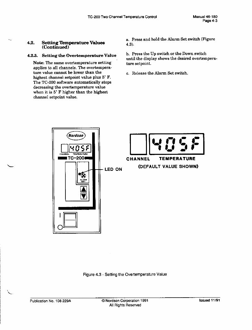
a. Press and hold the Alarm Set switch (Figure
(Continued) 4.3).
4.2.3. Setting the Overtemperature Value
’ Note: The same overtemperature setting applies to all channels. The overtempera- ture value cannot be lower than the highest channel setpoint value plus 5” F. The TC-200 software automatically stops decreasing the overtemperature value when it is 5’ F higher than the highest channel setpoint value.
b. Press the Up switch or the Down switch until the display shows the desired overtempera- ture setpoint.
c. Release the Alarm Set switch.
CMAMMIL TtYPtaAluaL
m TC-200-
l&l
Irl
\
- LED ON
CHANNEL TEMPERATURE
(DEFAULT VALUE SHOWN)
Figure 4.3 - Setting the Overtemperature Value
Publication No. 108 229A 0 Nordson Corporation 1991 All Rights Reserved
Issued 1 l/91

Manual 46-l 80 Page 4-4
TC-200 Two Channel Temperature Control
4.2. Setting Temperature Values (Continued)
4.2.4. Setting Setpoint Temperatures
Note: A setpoint temperature must be set for each channel. The setpoint temperature for each channel must be be- tween the Standby and Overtemperature values. To select a setpoint temperature that is lower than the current Standby temperature, or higher than the current Overtemperature value, first adjust those values accordingly.
a. Press and release the Scan switch (Figure 4.4) until the Scan Mode Active LED is off.
LED OFF
LED ON-
CWAWWL TtNlln~t~~
-TC-200m
\
b. Press and release the Up switch or the Down switch until the display shows the desired chan- nel number.
c. Press and hold the Temp Set switch (Figure 4.4). The display shows the current setpoint temperature.
Note: To leave the current value un- changed, release the Temp Set switch.
d. Press the Up switch to increase the value or the Down switch to decrease the value.
e. Release the Temp Set switch when the dis- play shows the desired temperature value.
Note: The maximum temperature set- point is 400” F.
4
CHANNEL I
TEMPERATURE
(DEFAULT VALUE SHOWN)
Figure 4.4 - Setting Setpoint Temperatures
Issued 1 l/91 0 Nordson Corporation 1991 All Rights Reserved
Publication No. 108 229A

TC-200 Two Channel Temperature Control Manual 46-l 80 Page 4-5
4.3. Placing the TC-200 in the Standby Mode
b. To exit the Standby mode and return to the Run mode, press and hold the Standby switch until the Standby Active LED goes off.
a. Press and hold the Standby switch until the Standby Active LED comes on. The display will show the channel and its actual
temperature. The Wait LED will stay on until The Wait LED comes on. The display will ap- all channel temperatures are within their set- pear as shown in Figure 4.5. The TC-200 cycles point band (+/- 10” F of their respective tempera- power off until the hot melt material reaches ture setpoints). Standby temperature. Then, it cycles power on and off to keep the material at Standby tempera- ture.
\
LED ON
p/mq CMANNEL TCYCEIIATURL
mTC-200 /
STAW8T WAIT
- LED ON CHANNEL TEMPERATURE
Figure 4.5 - Standby Mode Display and LED Status
Publication No. 108 229A 0 Nordson Corporation 1991 All Rights Reserved
Issued 1 l/91

Manual 46-160 Page 4-6
TC-200 Two Channel Temperature Control
4.4. Placing the Unit in Sleep Mode The second channel status message is shown in
a. Check that the Standby temperature is set to Figure 4.7, below. This display shows when no channels are connected.
151” F or less (66’ C; refer to paragraph 4.22.).
b. Press and hold the Standby switch until the Standby Active LED is on.
The Wait LED also comes on. The display con- r&q
tinues to show the actual temperatures. The TC- CHANNEL TEMPERATURE
200 removes power to the heating channels. The hot melt material then cools to room tempera-
Figure 4.7 - Display When No Channels Connected
ture.
c. To exit the Sleep mode and return to the Run mode, press and hold the Standby switch until the Standby Active LED turns off. The dis- play will show the channel and its actual temperature. The Wait LED will stay on until all channel temperatures are in the setpoint band.
4.5. Channel Status Messages
The TC-200 can display two channel status mes- sages.
The first channel status message is the low temperature indication (Figure 4.6, below). This display shows when a channel temperature is below 150“ F (66 ’ 0.
CHANNEL TEMPERATURE
Figure 4.6 - Low Temperature Display
Issued 11/91 0 Nordson Corporation 1991 All Rights Reserved
Publication No. 108 229A

TC-200 Two Channel Temperature Control Manual 46-l 80 Page 4-7
4.6. Error Messages
There are three error messages that the TC-200 can display. The Alarm LED is on while any error condition exists.
Note: If the error condition goes away within 45 seconds, the error message goes away and the Alarm LED turns off.
After an error condition continues for longer than 45 seconds, the TC-200 removes power from the heaters. If the error condition goes away, the TC-200 on/off rocker switch must be turned off, then on. Otherwise, the display will still show the error message, and the chan- nels will not resume heating.
Each error message display and a brief explana- tion of its cause are shown below. Corrections for the problem are covered in the Troubleshoot- ing Guide in Section 5.
Figure 4.8 - A channel’s actual temperature is greater than the over-temperature value. When displayed, that channel will appear as shown below. The Alarm LED is on.
Figure 4.9 - A channel RTD has an open circuit. When displayed, that channel will appear as shown below. The Alarm LED is on.
CHANNEL TEMPERATURE
Figure 4.9 - RTD Open Circuit
Figure 4.10 - A channel RTD has a short circuit. When displayed, that channel will appear as shown below. The Alarm LED is on.
CHANNEL TEMPERATURE
Figure 4.10 - RTD Short Circuit
Figure 4.8 - Alarm Overtemperature Display
Publication No. 108 229A 0 Nordson Corporation 1991 All Rights Reserved
Issued 1 l/91


TC-200 Two Channel Temperature Control Manual 46-l 80 Page 5-1
-
Section 5 Troubleshooting
6.1. Introduction
In this section, you will find the troubleshooting guide. The symptoms are followed by possible causes listed in order of probability.
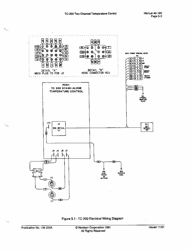
The TC-200 wiring diagram (Figure 5.1) and schematic (Figure 5.2) are located at the end of this section.
5.2. Safety During ‘Ikoubleshooting
A Warning: Before performing the follow- ing troubleshooting procedures, thoroughly review SECTION 1, SAFETY SUMMARY, in this manual. Only qualified personnel should perform the following procedures.
A Warning: It is imperative that person- nel operating, maintaining, or troubleshooting the TC-200 refer to the
technical manuals for the bulk melter, applicator, and/or its associated equip- ment. The manuals provide important safety, operation, and troubleshooting information used in conjunction with procedures presented in this manual.
Warning: Even when switched off, the TC-200 contains energized components with electrical potentials that can cause death. Disconnect and lock out the input power line to the TC-200 before checking or making any wiring connec- tions. Only qualified personnel should make such checks or connections.
Table 5.1 - Troubleshooting Guide
resistance; replace RTD if defec- tive. If RTD ok, check for open RTD circuit; repair open circuit.
Publication No. 108 229A 0 Nordson Corporation 1991 All Rights Reserved
Issued 11191
ManuaM-180 Page52
TC-200 Two Channel Temperature Control
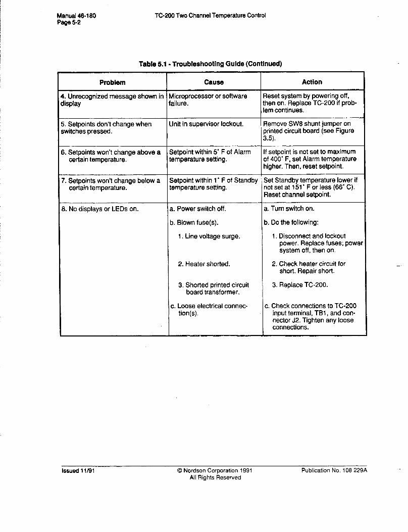
Table 5.1 - Troubleshooting Guide (Continued)
b. Do the following:
1. Line voltage surge. 1. Disconnect and lockout power. Replace fuses; power system off, then on.
2. Heater shorted. 2. Check heater circuit for short. Repair short.
3. Shorted printed circuit board transformer.
3. Replace TC-200.
c. Loose electrical connec- c. Check connections to TC-200
-
Issued 1 l/91 0 Nordson Corporation 1991 All Rights Reserved
Publication No. 108 229A --
TC-200 Two Channel Temperature Control Manual 46-180 Page 5-3
OETAIL "A' OETAIL “B” MR20 PLUG TO PC8 J2 HOSE CONNECTOR HCl
. . . . . . . . . . . . . . . . . . . . . . . . . . ..a
PCS 1 TC 200 STAND-ALONE
TEMPERATURE CONTROL
J2
SEE DETAIL . .A’
I--
J8 J9 J6 J7
HCl A
** 43 L
,
@cm- Fl
Figure 5.1 - TC-200 Electrical Wiring Diagram
Publication No. 108 229A 0 Nordson Corporation 1991 All Rights Reserved
Issued 1 l/91

Manual 46-180 Page 5-4
TC-200 Two Channel Temperature Control
GSi - INTERNAL MOWTING PLATE
6S2 - ALUMIMJM HEAT SINK
6S3 - ALUMINW GRAPHICS PLATE
64 66 I
.r”i 6S2 6S3
h
I/O CONNECTIONS 4ziiimTm STANmY ALARM 6ta L2 Li 4cYrxrYYr t, , , 1 , 1
3 2 1
19 16 17 16 61 2A 1A c
1
-
1 63
A A A A A A A mm m mmmm
3
PCB 1 TC 200 STAND-ALONE TEMPERATURE CONTROL
*
DETAILS SHOWN FOR REFERENCE Of&Y AND SHOULD NOT BE INTEWRETEO LITERALLY.
Figure 5.2 - TC-200 Electrical Schematic (1 of 2)
Issued 11/91 0 Nordson Corporation 1991 All Rights Reserved
Publication No. 108 229A . ,i

TC-200 Two Channel Temperature Control Manual 46-180 Page 5-5
63 61
u13
-I+ jl
+ 6Sl
62
HEATERS AND ATDs SHObdN FOR REFERENCE ONLY -----------------------------------------
LONE 1 zolE2 OfOSE) MlMl
MC1 ---------- -------
I7
I ‘\ I i Ii’-:
fy-3!2xii-,/ > <
L -B-B----- J
Figure 5.2 - TC-200 Electrical Schematic (2 of 2)
Publication No. 108 229A 0 Nordson Corporation 1991 All Rights Reserved
Issued 11/91


TC-200 Two Channel Temperature Control
Section 6 Parts List
Manual 46-l 80 Page 6- 1
6.1. Introduction
This section contains the parts list for the TC- 200.
assembly of the part. A part preceded by one bullet (0) is a component of the assembly above it.
6.1.1. Using the Parts List
The three column parts list provides:
l the Nordson@ Part Number.
l the part’s Description. The part’s name, dimensions, and physical properties are provided. Bullets indicate the level of
l the Req’d column indicates the quantity requirements per unit or assembly. If the item is listed for reference only, “Ref’ or a dash appears in the column. The dash is used for items that exist in a nonquantitative form.
Table 6.1 - TC-200 Parts List -
Part Number Description Req’d
136 899 ‘-
939 683
136 930
136 923
-
l Switch, Rocker, DPDT, 250 VAC
Interface Cords, 12 Pin Feed-through (Hose) -
145 211 l Cord, Hose, 2 Ft, TC-200 Ref
145 212 l Cord, Hose, 6 Ft, TC-200 Ref
145 213 l Cord, Hose, 12 Ft, TC-200 Ref
145 214 l Cord, Hose, 18 Ft, TC-200
l Cord, Hose, 24 Ft, TC-200
Ref
145 215 Ref
145 216 l Cord, Hose, 30 Ft, TC-200 Ref
Control, Temperature, Stand-alone, TC-200
l Fuse, 6.3A/25OV
l Fuseholder, Panel, 5 x 20
Ref
Publication No. 108 229A 0 Nordson Corporation 1991 All Rights Resewed
Issued 11/91

Manual 46-l 80 Page 6-2
TC-200 Two Channel Temperature Control
Table 6.1 - TC-200 Parts List (Continued)
Part Number Description Req’d
125 364 Cordset, Splitter, 2 Gun, 2300 (splits 12 pin Ref connector into two 6 pin connectors)
- Interface Cords, 6-Pin Feed-through (Gun) -
145 217 l Cord, Gun, 2 Ft, TC-200 Ref
145 218 l Cord, Gun, 6 Ft, TC-200 Ref
145 219 l Cord, Gun, 12 Ft, TC-200 Ref
145 220 l Cord, Gun, 18 Ft, TC-200 Ref
145 221 l Cord, Gun, 24 Ft, TC-200 Ref
Issued 11/91 0 Nordson Corporation 1991 All Rights Reserved
Publication No. 108 229A

TC-200 Two Channel Temperature Control
Section 7 Technical Data
Manual 46-l 80 Page 7-l
7.1. TC-200 Temperature Control Specifications
7.1.1. Operator Interface
LED Screen . . . . . . . . . . . . . . . . . . . . . . . . . . . . . . . . . . . . . . . . . . . . . . . . . . . . . . . . . . . . . . 7-segment LED-type display
Set-up Controls . . . . . . . . . . . . . . . . . . . . . . . . . . . . . . . . . . . . . . . . . . . . . . . . . . . . . . . . . Keyswitch input for process setpoint adjustment
Control Mode . . . . . . . . . . . . . . . . . . . . . . . . ...*.... . . . . . . . . . . Two separate and independent PI-type temperature control loops
Setpoint Control Range . . . . . . . . . . . . . . . . . . . . . . . . . . . . . . . . . . . . . . . . . . . . . . . . . . . . . . . . . . . . . . . . . . . . . 151” - 400” F
7.1.2. Electrical Specifications
Inputs
Input Voltage . . . . . . . . . . . . . . . . . . . . . . . . . . . . . . . . . . . . . . . . . . . . . . . . . . . . . . . . . . . . . . . . . . . 200/240 VAC, 50/60 Hz, single phase only
Fusing . . . . . . . . . . . . . . . . . . . . . . . . . . . . . . . . . . . . . . . . . . . . . . . . . . . . . . . . . . . . . Load heaters fused 6.3A, 250 VAC
Sensors . . . . . . . . . . . . . . . . . . . . . . . . . . . . . . . . . . . . . . . . . . . . . . . . . . . . . . . . . . RTD-type, two-wire, nickel element
Remote Temperature Setback Enable . . . . . . . . . . . . . . . . . . . . . . . . . . . . . . . . . . . . . ..a. Contact closure (5 VDC, 1 mA)
outputs
Heater Output Switches ,.............................,....................... Zero cross-Triac type
Maximum Switched Power . . . . . . . . . . . . . . . . . . . . . . . . . . . . . . . . . . . . . . . . . . . . . . . . . . . . . . . . . 700W @ 240VAC
Remote Unit Fault Alarm . . . . . . . . . . . . . . . . . . . . . . . . . . . . . . . . . . . . . . . . . . . . . . . . . . . . . . . . . . . . . Contact closure (1 Form A, SPST 250 VAC, 5A)
Remote Unit System Ready . . . . . . . . . . . . . . . . . . . . . . . . . . . . . . . . . . . . One open collector transistor (25 VDC, O.lA)
Publication No. 108 229A 0 Nordson Corporation 1991 All Rights Reserved
Issued 11/91

Manual 46-l 80 Page 7-2
TC-200 Two Channel Temperature Control
7.1.3. Dimensions
Height . . . . . . . . . . . . . . . . . . . . . . . . . . . . . . . . . . . . . . . . . . . . . . . . . . . . . . . . . . . . . . . . . . . . . . . . . . . . . . . . . . . . . . . . . 10.5 in. (26.7 cm)
Width . . . . . . . . . . . . . . . . . . . . . . . . . . . . . . . . . . . . . . . . . . . . . . . . . . . ..*...................................... 8.5 in. (21.6 cm>
Depth . . . . . . . . . . . . . . . . . . . . . . . . . . ..*............................................................... 4.5 in. (11.4 cm)
7.1.4. Safety
Sensor Indication . . . . . . . . . . . . . . . . . . . . . . . . . . . . . . . . . . . . . . . . . Open and shorted sensor indication
Power Removal . . . . . . . . . . . . . . . . . . . . . . . . . . . . . . . . . . . . . . . . . . . . . . . . . . . . . . . . . Adjustable overtemperature safety power removal
7.1.5. Operating Environment
Operating Temperature . . . . . . . . . . . . . . . . . . . . . . . . . . . . . . . . . . . . . . . . . ...*.... 20" - 120" F (-7” to 49” C)
Issued 11/91 0 Nordson Corporation 1991 All Rights Resewed
Publication No. 108 229A