public works technical bulletin 200-1-100 03 · pdf filepublic works technical bulletin...
TRANSCRIPT
PUBLIC WORKS TECHNICAL BULLETIN 200-1-100 03 JUNE 2011
SELECTION OF REINFORCED VEGETATION AND HARD ARMORING TECHNIQUES

Public Works Technical Bulletins are published by the U.S. Army Corps of Engineers, Washington, DC. They are intended to provide information on specific topics in areas of Facilities Engineering and Public Works. They are not intended to establish new Department of Army policy.

DEPARTMENT OF THE ARMY U.S. Army Corps of Engineers
441 G Street NW Washington, DC 20314-1000
CECW-CE
Public Works Technical Bulletin 03 June 2011
No. 200-1-100
FACILITIES ENGINEERING ENVIRONMENTAL
SELECTION OF REINFORCED VEGETATION AND HARD ARMORING TECHNIQUES
1. Purpose.
a. This Public Works Technical Bulletin (PWTB) details the basic technologies and techniques (including the selection process) for reinforced vegetation and hard armoring that is needed to maximize the safety, success, efficiency, and cost benefits of soil stabilization efforts on military installations. It is meant to be used as a primer to help Army personnel identify and understand the technologies and materials available for (and the basic engineering concepts behind) steep slope stabilization and erosion control to support military activities.
b. All PWTBs are available electronically at the National Institute of Building Sciences’ Whole Building Design Guide webpage, which is accessible through this link:
http://www.wbdg.org/ccb/browse_cat.php?o=31&c=215
2. Applicability. This PWTB applies to engineering activities at all U.S. Army facilities.
3. References.
a. Army Regulation (AR) 200-1, “Environmental Protection and Enhancement,” 13 December 2007.

PWTB 200-1-100 03 June 2011
2
b. Executive Order (EO) 13514, “Federal Leadership in Environmental, Energy and Economic Performance,” 5 October 2009.
c. References cited in the Appendices are listed in Appendix D.
4. Discussion.
a. AR 200-1 requires that military installations care for land resources, to prevent the wind and water erosion caused by installation activity from damaging equipment, land, and water resources.
b. The costs of unsuccessful periodic or regularly scheduled land rehabilitation efforts on military lands can easily consume the budgets of an installation’s Directorate of Public Works (DPW) and Natural Resource offices. Reinforced vegetation and hard armoring, two of the more dominant mechanisms for rehabilitation of steep gradient land areas, can be extremely costly on a per acre basis. Without proper installation of these materials to match soil type, gradient, hydraulic resistance, and soil strength, these products may not perform as intended by the design. Since these materials are frequently placed in areas with steep gradients where improved slope stability is required to resist high water velocities and soil shear stresses, failure avoidance is crucial. When considering the elevations and gradients where these materials are applied, product failure can be life threatening. Proper guidance regarding the use and maintenance of these materials is essential to a successful long-term installation.
c. This PWTB provides a guide for the selection of techniques and technologies regarding the use and implementation of steep slope stabilization materials. These products stabilize soils and prevent soil movement over a wide range of land forms, providing erosion control for sites that are disturbed, sloped, or both. These products also assist in vegetative reestablishment, leading to long-term erosion control.
d. Appendix A contains background information on hard armoring and reinforced vegetation techniques, materials, and products. These products are composed of several components, and each component is used differently depending on several environmental and site-specific factors.
e. Appendix B summarizes each of the steep slope and erosion control technologies best management practices (BMPs) to aid in the selection of hard armoring and reinforced vegetation

PWTB 200-1-100 03 June 2011
A-1
Appendix A:
INTRODUCTION
Steep slopes, unstable soils, and high water flows all present problems for revegetation practices on disturbed military lands. Soil stabilization is a key component in successfully reestablishing vegetation on disturbed slopes, channels, and banks. Seeding without stabilizing the soil surface can be a costly venture with unfavorable results. Choosing the correct technology to use can present significant risk since under-engineered and under-qualified technologies and techniques could present safety issues for people and property if failure occurs. Furthermore, if the technology or technique originally selected is over-qualified and over-engineered, money is wasted. Therefore, a selection process must be designed to choose steep slope stabilization products and methodologies that maximize success, safety, efficiency, and cost benefits.
The likelihood of failure can be reduced if slope stabilization products are chosen based on soil type, slope, hydraulic resistance, and soil strength. Cost can be controlled by choosing products that are less costly, easy to install, and easy to maintain. Soft engineering solutions and reinforced vegetation are available for slope stabilization, just as there are hard engineering solutions and hard armoring. Each of these practices has its place. In many cases, both can achieve the same general goal of protecting an exposed slope. Soft engineering practices, which are a mix between hard and soft practices, will be the focus of this PWTB because soft engineering practices tend to promote vegetation growth and increase soil shear and tensile strength. Vegetation on slopes is considered to be a long-term stabilization technique compared with concrete and steel because it adapts to its surroundings while having a longer life expectancy than manmade materials when properly maintained.
Commonly used products in stabilizing steep slopes are geonaturals (natural fiber geomaterials), geosynthetics (manmade geomaterials), and hard armoring (cementitious materials). Many times geonaturals and geosynthetics are combined into one product and called geocomposites. The geocomposites covered in this PWTB include turf reinforcement mats (TRMs). Geosynthetics discussed include other TRMs, high-performance turf reinforcement mats (HPTRMs), geocells (GCEs), and geogrids (GGRs). Two hard-armoring techniques included are Articulated

PWTB 200-1-100 03 June 2011
A-2
Concrete Block Mats (ACB Mats) and Interlocking Concrete Blocks (ICBs); these products typically utilize other geosynthetics and anchors for reinforcement. Flexible geomaterials will be the primary focus of this PWTB, as flexible geomaterials can most often be vegetated. Each product will be discussed in detail outlining the advantages and disadvantages of each.
Turf Reinforcement Mats
TRMs are three-dimensional in nature and composed of synthetic and natural fibers. (Note that “TRMs” can be used to mean either “Composite Turf Reinforcement Mats” or “Turf Reinforcement Mats,” since many TRMs are composites of multiple materials.) Synthetic fibers used to make TRMs include polyester, polyethylene, and nylon. Some mats use natural fibers or yarns in addition to synthetics to form a three-dimensional matrix. Because TRMs are non-biodegradable, they are intended to be a permanent application to enhance root reinforcement at the soil surface. TRMs are tested to ASTM Standard D6460 (2007). This test allows for a loss of 0.5 in. of soil after testing in specified controlled flow conditions.
TRMs can be categorized by their development within the industry into two classes: a first generation TRM (commonly referred to as an ordinary TRM), and a second generation TRM (commonly referred to as an advanced TRM). Ordinary TRMs typically are composite TRMs, and are used for low flow, low shear stress applications. Typically, ordinary TRMs have a design life of up to 10 years, with a tensile strength of up to 400 lb/ft per ASTM Standard D6818 (2009) and a UV resistance of 80% at 1,000 hours per ASTM Standard D4355 (2007). Some advanced TRMs can be used for more critical applications with higher shear stress and higher velocities, and are homogenous with a woven construction. Some advanced TRMs have a design life of up to 25 years, with a tensile strength of up to 1,500 lb/ft per ASTM Standard D6818 (2009) and a UV resistance of up to 90% at 3,000 hours per ASTM Standard D4355 (2007).
TRMs allow unstable soils or unstable landform regions to be successfully vegetated because they continue to support root structure and ground cover even after plant establishment. TRMs are designed to be used where vegetation alone cannot withstand the overland flow conditions on a slope or bank. Allowable shear stresses can be doubled for grasses when using many TRMs (Shukla and Yin 2006). Such an increase in tolerable stresses allows areas that were once reinforced only by hard engineering practices to be seeded instead.

PWTB 200-1-100 03 June 2011
A-3
TRMs are a newer type of RECP and can be seeded in two different ways. The first method calls for seeding underneath the blanket. By seeding first, the plants are allowed to grow through the mat much like an erosion control blanket (ECB). The second seeding method is to install the mat first. When the mat is installed before seeding, a layer of soil is spread over the top of the mat and then seeded. By seeding above the mat, roots are allowed to grow through the mat and into the soil profile underneath.
The chosen method of seeding depends on the conditions present at a particular time of year. Potential erosion should be considered so as not to lose the new seed during storm events. As roots integrate into the mat and begin to grow into the soil surface beneath the mat, detachment and undercutting is less likely. If seeding is done after installing the mat, an ECB will be needed; otherwise, the TRM should serve the same purpose as an ECB (Kilgore and Cotton 2005). The second method of seeding has a maintenance advantage, which is important to consider when installing TRMs. Since the majority of the TRM has been placed beneath the soil, land management activities such as mowing become easier.
Many TRMs consist of a geogrid, a synthetic mesh with high tensile strength and synthetic fibers to provide long-term protection. The mat grids and synthetic fibers are joined through stitching, lamination, or thermal bonding. This combination creates a matrix consisting of 90% voids and is the reason TRMs are often buried in the uppermost layer of topsoil. Through this method, the soil is seeded and then the roots incorporate into the mat and the soil beneath. Throughout the vegetation establishment period, the TRM acts to control erosion. For convenience of application, TRMs can be broken down into four groups organized by maximum slope, allowable shear stresses, and flow velocities. According to South Carolina Department of Health and Environmental Control (2005), these types are:
Type 1: o No steeper than 2:1 height to vertical (H:V) slopes o Less than 4.0 lb/ft2 (19.5 kg/m2) or calculated shear stress o Flow velocity of less than 10 ft/sec (3.0 m/sec)
Type 2: o No steeper than 1.5:1 (H:V) slopes o Less than 6.0 lb/ft2 (29.3 kg/m2)or calculated shear stress o Flow velocity of less than 15 ft/sec (4.6 m/sec)

PWTB 200-1-100 03 June 2011
A-4
Type 3: o No steeper than 1:1 (H:V) slopes o Less than 8.0 lb/ft2 (39.1 kg/m2)or calculated shear stress o Flow velocity of less than 20 ft/sec (6.1 m/sec)
Type 4: o No steeper than 1:1 (H:V) slopes o Less than 12.0 lb/ft2 (58.6 kg/m2)or calculated shear stress o Flow velocity of less than 25 ft/sec (7.6 m/sec)
Many TRMs are on the market today (Figure A-1), and vendors make product differentiation difficult as each claims to have their own subtle differences and enhancements. However, most critical to consider are the product’s structural limitations and the intended environmental and physical limitations. Listed below are situations where TRMs are not recommended (USEPA 1999).
Slopes steeper than 1:1 (H:V) Prevention of failure for reasons other than surface
erosion Hydraulic events exceeding the limits of the manufacturer’s
specification Dissipation of energy below outlets Where wave heights greater than 1 ft (0.3048 m) would
impact the mat.
Installation of TRMs is similar to that for ECBs (Propex Geosynthetics 2008).
The area of concern must be graded and compacted to the manufacturer’s specifications.
All debris (e.g., clods, rocks, branches, vegetation) must be removed.
The first 2-3 in. (5-7 cm) of the soil surface must be loosened.
Seed is then planted either before or after installing the TRM, depending on the characteristics of the product and maintenance requirements of the area.
Methods of attaching TRMs to the ground may vary significantly by product; therefore, it is crucial to follow each product’s specifications and to work closely with the manufacturer to ensure proper installation.
Maintenance of TRMs includes close inspection weekly and after each storm event until vegetation is established. Once
PWTB 200-1-100 03 June 2011
A-5
vegetation is established, the chance of failure decreases. However, several events could occur that may precipitate an installation failure including anchoring issues, undercutting, significant flow events, and damage from outside sources. Anchoring effectiveness can be increased by following the manufacturer’s pin configuration, adding more pins, and burying the tops and bottoms of the mat in trenches (“keying in”). Undercutting occurs because of improper preparation and installation. To ensure proper installation, all debris should be removed and rills should be filled in to ensure good contact between the soil surface and the mat. If complete failure occurs because flows are too high, additional management practices should be implemented to reduce contributing flows. These practices include surface hardening and roughening, upland infiltration, and temporary or permanent diversion.
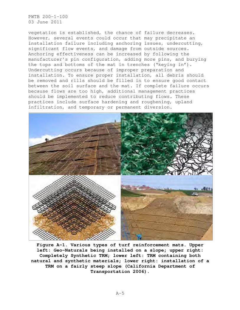
Figure A-1. Various types of turf reinforcement mats. Upper left: Geo-Naturals being installed on a slope; upper right: Completely Synthetic TRM; lower left: TRM containing both
natural and synthetic materials; lower right: installation of a TRM on a fairly steep slope (California Department of
Transportation 2006).

PWTB 200-1-100 03 June 2011
A-6
High Performance Turf Reinforcement Mats
HPTRMs (Figure A-2) are very similar to TRMs. An HPTRM has to have a minimum tensile strength of 3,000 lb/ft per ASTM Standard D6818 (2009). This tensile strength is what defines an HPTRM according to the USEPA, and that strength also is required for any high-survivability and high-loading conditions, whether those conditions are the result of a hydraulic stress or a non-hydraulic stress. Examples of non-hydraulic stresses include maintenance vehicles, mowing equipment, and animal traffic.
HPTRM materials are made of polypropylene weaves, and some manufacturers include steel reinforcement. Each layer has its own purpose: (a) the netting layer holds the mat together and binds it to the surface; (b) the fiber mat layer dissipates rain drop energy and slows down sheet flow; and (c) the three-dimensional layer helps to hold soil on top and assists in establishing root structure. Unlike TRMs, HPTRMs always consist of synthetic materials. Synthetics are desirable because of their long life, strength, and flexibility. HPTRMs, with high UV resistance of up to 90% at 6,000 hours of exposure per ASTM Standard D4355 (2007), are recommended in areas where vegetation is not expected to establish well or quickly. Their long life and high strength makes these mats ideal for arid and semi-arid climates where the mat will provide surface protection and prevent shallow plane failures.
Figure A-2. Pyramat HPTRM (Propex Geosynthetics 2008).
PWTB 200-1-100 03 June 2011
A-7
As mentioned above, HPTRMs are much stronger than TRMs, with allowable hydraulic loads reaching 15 lb/ft2 (718 N/m2), velocities as great as 25 ft/s (7.62 m/s), and slopes equal to or greater than 1:1 (H:V). Semi-permanent anchors are commonly used with HPTRMs because they are meant for a more permanent stabilization on unstable soils. Percussion driven earth anchors (PDEAs) are one type of anchor to use with HPTRMs. Anchors can withstand maximum pull outs from 500 lb (226.8 kg) up to 5,000 lb (2,268 kg). When HPTRMs are used in conjunction with PDEAs, the solution is referred to as an anchored reinforced vegetation system (ARVS). Both the PDEAs and HPTRM have to be provided by one manufacturer to ensure ARVS performance. A nonstructural ARVS will provide for permanent tie-down when higher factors of safety are required for critical applications such as levees which experience overtopping. PDEAs are driven up to 3 ft into the soil for non-structural applications. PDEAs which are longer than 3 ft will typically be used for structural ARVS applications when slope stability is required or resistance to shallow plane failures is needed, and surface erosion is not the only concern. HPTRMs are tested to ASTM Standard D6460 (2007). This test allows for a loss of 0.5 in. of soil after testing in specified controlled flow conditions.
Geocells
Originally adopted in the 1970s by the U.S. Army Corp of Engineers (USACE) for stabilizing road bases, GCEs have taken on new roles (Geosynthetics 2009) and are appropriate for the uses listed below.
Slope stabilization and revegetation Channel banks and bed lining Temporary low water stream crossings Temporary and long-term parking lots and roads Retaining wall construction
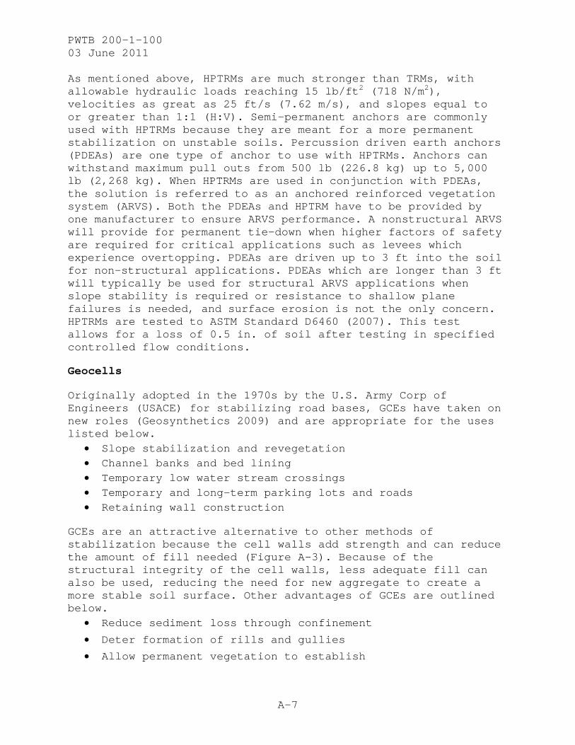
GCEs are an attractive alternative to other methods of stabilization because the cell walls add strength and can reduce the amount of fill needed (Figure A-3). Because of the structural integrity of the cell walls, less adequate fill can also be used, reducing the need for new aggregate to create a more stable soil surface. Other advantages of GCEs are outlined below.
Reduce sediment loss through confinement
Deter formation of rills and gullies
Allow permanent vegetation to establish
PWTB 200-1-100 03 June 2011
A-8
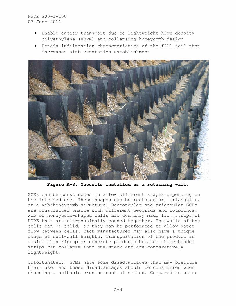
Enable easier transport due to lightweight high-density polyethylene (HDPE) and collapsing honeycomb design
Retain infiltration characteristics of the fill soil that increases with vegetation establishment
Figure A-3. Geocells installed as a retaining wall.
GCEs can be constructed in a few different shapes depending on the intended use. These shapes can be rectangular, triangular, or a web/honeycomb structure. Rectangular and triangular GCEs are constructed onsite with different geogrids and couplings. Web or honeycomb-shaped cells are commonly made from strips of HDPE that are ultrasonically bonded together. The walls of the cells can be solid, or they can be perforated to allow water flow between cells. Each manufacturer may also have a unique range of cell-wall heights. Transportation of the product is easier than riprap or concrete products because these bonded strips can collapse into one stack and are comparatively lightweight.
Unfortunately, GCEs have some disadvantages that may preclude their use, and these disadvantages should be considered when choosing a suitable erosion control method. Compared to other

PWTB 200-1-100 03 June 2011
A-9
techniques that are equally effective, GCEs cost more in labor and may take longer to ship. They also may require that other products be used initially to protect the exposed surface from erosion until vegetation has been established. The maximum slope on which GCEs may be installed is 1:1 (H:V); however, a significant soil loss may occur at first if the area is not properly covered with an ECB. GCEs may be used on smooth, prepared slopes, but not on rock slopes.
GCEs work well as a permanent BMP and should not be used as a temporary erosion control method even though they do work to contain overland flow and runoff. Removal of GCEs from an installation results in their destruction and makes their use cost-prohibitive. As with any other erosion control method, GCEs can be highly effective only if they are installed properly and then correctly vegetated and maintained (California Department of Transportation 2006).
Geogrids
GGRs are created by polyester or polypropylene extrusion and/or weaving, which is then coated with a polymer. There are two main types of GGRs: uniaxial and biaxial. Uniaxial GGRs have been extruded in only one direction, making them very strong in line with that extrusion. Biaxial GGRs have been extruded in both directions, making them equally strong in both directions, but not as strong in either direction as a similar uniaxial GGR. Uniaxial GGRs are used for primary reinforcement in mechanically stabilized earth (MSE) faces and reinforced soil slopes. Biaxial grids are used for secondary reinforcement and wrapped-face embankments, another form of MSE. GGRs are used in a variety of applications, but this PWTB will look at MSE walls and slopes (Geosynthetics 2009).
Permanent MSE structures can include slopes and walls as defined by the degree of slope. Slopes are less than 1:1 (H:V) and walls are greater than 1:1 (H:V). MSE slopes and walls are simply vegetated slopes that have been reinforced with GGRs to interfere with failure surfaces.
Reinforced soil slopes (RSS) are those slopes between 3:1 and 1:1 (H:V). Many slopes less than 3:1 can effectively establish vegetation and be considered stable slopes. Once the slope becomes steeper than 1:1, vegetation will become harder to establish with many erosion control products. Stabilizing these soils requires a series of primary and secondary GGRs throughout

PWTB 200-1-100 03 June 2011
A-10
the slope to increase the factor of safety to an acceptable level. Figure A-4 shows an RSS with the GGR arrangement.
Figure A-4. Failure surfaces in a reinforced soil slope.
Figure A-4 also depicts how the uniaxial and biaxial GGRs are used to reinforce this steep slope face. The uniaxial grids are the longer grids extending farther back into the slope, and the biaxial GGRs are used to provide secondary enforcement. Failure surfaces (e.g., internal, compounding, and global) are an important consideration when designing MSE walls. Internal failure is contained within the reinforcement materials, while compounding failure occurs outside the reinforcement materials but passes through the material and out through the foundation. Global failure is a deep line stretching from outside the reinforcement material down into the foundation soils (Strata Systems 2008).
A slope exceeding 1:1 (H:V) needs to have a wrapped face to prevent soil from eroding and to allow for long-term stability of the soil surface. Because the soil surface is more stable, MSE walls with wrapped faces can easily be vegetated. The primary GGR can be the same type as used in an RSS, but the secondary GGR must be able to encapsulate soil particles. If the

PWTB 200-1-100 03 June 2011
A-11
backfill is finer in texture, a geotextile, or another form of RECP, may have to be used behind the secondary GGR. The secondary GGR is the part used to wrap around the face of slope as depicted in Figure A-5. The difference between Figure A-5 and an actual wrapped face is that each step would actually have a sloped face rather than a perpendicular face. In this case, the primary grids are installed between two meeting secondary grids that have wrapped around the face of the slope. It should be kept in mind that, as time progresses and no vegetation has been established, the wraps on the face of the slope may begin to sag and slough; therefore, quick establishment of vegetation is essential.
Figure A-5. Vegetated earthen embankment geogrids wrapped with welded wire fabric (Kilgore and Cotton 2005).
Metal fabric grids can also be used to deter sagging, and should always be used for slopes steeper than 1:1. Reinforced faces consist of grates or frames with fabric bent in a 90° angle to
PWTB 200-1-100 03 June 2011
A-12
form extruded L-shapes. These panels then sit on the surface to be filled behind and at the wall face. All of the GGRs used in this particular design of MSE walls (Figure A-5) are attached to the facing. The pictured design also shows a wall face reinforced with welded wire fabric (WWF).
Vegetated MSE slopes and walls are an appealing slope reinforcement design because they are less expensive than concrete block structures. Expenses are reduced because there is less need for skilled labor, less excavation behind the wall face, and reuse of onsite fill rather than borrowing fill. These systems are also flexible to move with surface changes.
However, MSE slopes and walls should be used only where usable land is limited. These methods are mainly employed in urban conditions at the edge of property lines, where employing a steeper slope means more usable space. A large amount of excavation, earthwork, and time is required for vegetation establishment. MSE walls especially would not be cost effective for slopes less than 1:1 or where stable soils are present.
For more information on MSE structures, consult the Federal Highway Administration (FHWA) publication (2009)on the subject (see Appendix D).
Articulating Concrete Block Mats
Vegetated “soft” engineering practices can be effective techniques for controlling soil erosion; however, in some instances, vegetation and its non-rigid reinforcement cannot withstand design soil conditions, shear stresses, flow velocities, and traffic requirements. Articulating concrete block (ACB) mats are a “harder” engineering BMP that can support vegetative growth and meet hardened design requirements.
ACB systems comprise interconnected concrete blocks, a geotextile underlayment, and sometimes cables tying the blocks together into a hardened matrix. These concrete blocks are joined together by geometric interlock, polyester cables, or steel cables. A flexible bond between the individual units allows the blocks to conform to the soil surface and continue to provide hardened protection even if the subgrade may change slightly (Figure A-6). ACBs are tested to ASTM Standard D7277 (2008). This test accounts for no loss of soil beneath the geotextile and ACB system after specified control flow conditions.

PWTB 200-1-100 03 June 2011
A-13
Figure A-6. ACB installed on open channel embankment.
ACBs can be hand-placed on site without cables, hand-placed and cabled on site, or assembled off site. Installing systems held together by cables can provide significant cost savings if the necessary equipment can access the site. Cabled sections can be assembled off site but must be trucked in and installed with a crane, although smaller sections may be installed with a track hoe. All mats must be placed with spreader bars to keep the mats close to parallel with the slope on which it is to be installed to avoid damage to the mats. Mat sections can be quite long and require large equipment to be properly installed. The use of heavy machinery, deep anchors, geotextile underlayment, and concrete grout in anchor trenches and seams greater than 2 in. between mats make installing ACB mats more involved than installing TRMs or GCEs.
ACB mats are attractive compared to concrete, rip rap, gabion baskets, and Reno mattresses because of the ACB mats’ reduced installation labor intensity and their complement to traffic and soldiers. ACB mats are flexible yet constrained, have low profiles, and require no custom wire baskets for each site. Just as with other erosion control methods, a sufficient anchoring system—usually consisting of burying blocks in a termination trench along the edges—must be in place because ACB mats do not

PWTB 200-1-100 03 June 2011
A-14
stabilize the ground. The combination of the geotextile and ACB units will protect the soil surface from outside forces and keep the soil in place. ACB protection is used when soils are already stable and need to be protected from moving water or traffic. ACB units must be anchored and terminated into the stable subsoil to protect the edges from erosive forces.
ACB mats can be used for armoring cross sections, slope toes, side slopes, and culvert outlets. Concrete blocks used for protecting these critical sites have openings consuming 17%-23% of the block’s cross-sectional area. These openings allow fill soil to be placed within the mat and allow vegetation to be established above an underlying geotextile. Geotextiles should be nonwoven and should be needle punched rather than heat-bonded or resin-bonded. Needle-punched, nonwoven geotextiles allow higher rates of infiltration, when sized to the project site soils, which is a necessary component in minimizing runoff and erosion (Anderson 2003).
ACB mats should be considered only for those areas where other practices would be insufficient. These mats should be used in areas of vehicle traffic or where storm events necessitate hard armor. As with any other erosion control product, success depends on the quality of the installation.

PWTB 200-1-100 03 June 2011
B-1
Appendix B:
BEST MANAGEMENT PRACTICE GUIDES
TRM BMP
Location: TRMs should be used only on sites where permanent stabilization is necessary. Slope, flow velocity, ground cover, and traffic all affect where TRMs will be best suited. Slopes must be within 3:1 and 1:1 (H:V). If the slope is less than 3:1, an ECB will provide adequate protection; however, an HPTRM must be used on slopes steeper than 1:1. Grass alone should never be used in flow velocities exceeding 5 fps (feet per second). But with a TRM, flow velocities may still not exceed that recommended by the manufacturer. Potential soil surfaces should allow grading to occur and debris to be removed if needed. Grading will result in a smooth soil surface, and removing all sticks, rocks, and vegetation will provide a smooth surface so soil will come in contact with the mat. TRMs are not meant to serve as roadway reinforcement. Therefore, traffic should be little or none where TRMs are installed. Any traffic on the mats should be light and have rubber tires. No tracked vehicles should be permitted to drive on the mats.
Time: Time of installation will depend heavily on types of native plants being planted and rainfall. Certain native plant species require planting and then an extended period of time before germination; this period is dormancy. Some species may require an entire winter to come out of dormancy, while others may have none. Rainfall plays one of the largest roles in the success of a revegetation project. Rainfall determines the percentage of seed to germinate, and if there is too much rainfall, the seed washes away with the runoff.
Soil: Soils should be able to sustain vegetation and have the ability to become stable. Soil moisture will play a large role in determining the safety of applying the product, especially on such steep grades. An acceptable amount of moisture varies with soil type; in general, soils containing 50%-75% of field capacity are suitable for bearing traffic on slight to no

PWTB 200-1-100 03 June 2011
B-2
slope. When working on steep slopes, the acceptable amount of moisture will be much lower and will be dependent on the soil.
Installation of TRMs is not a complicated process; however, failure to follow manufacturer’s guidelines will not guarantee successful product performance.
Geocell BMP
Location: Useful applications of geocells include reinforcing roadways, constructing steep embankments, and stabilizing slopes. The purpose of this PWTB is to identify methods for reinforcing vegetation; therefore, reinforced roadways and low water stream crossings will not be included because the fill used is most likely gravel or other aggregate not harboring vegetation. Each potential site has ideal conditions, and it is the duty of the firm doing the installation to attempt to replicate those conditions in any situation.
Even under ideal conditions, GCE (like all other slope stabilization products), have limitations as to where they can be installed. GCEs should not be applied on slopes steeper than 1:1 (H:V) and are not cost effective for slopes less than 1:3. Slope faces should also not consist entirely of rock.
Time: Time of application will follow the same guidelines as a TRM. Installation may be done when planting is not ideal, but a temporary ECB will need to be installed on top of the new GCE until ideal seeding conditions are present.
Soil: Slope surfaces should be cleared of all debris including wood, vegetation, and rock. Unlike TRMs, GCEs will harbor vegetation with their cells filled with fertile aggregate. Prior to product installation, subsoil should be graded and compacted. Just as with TRMs, soil moisture should be within 50%-70% of field capacity. If the soil is too wet, compaction and product failure are likely to occur and, if the soil is too dry, new seed may have trouble germinating.

PWTB 200-1-100 03 June 2011
B-3
ACB/ICB BMP
Location: ACBs or ICBs combined with vegetation can be used for channel linings, slope stabilization, outlet protection, and where scouring is prevalent. ACB systems are used where soil conditions, flow velocities, or heavy traffic limit the use of softer engineering practices. Cabled concrete or interlocking blocks are substantially heavier than all other mentioned soil stabilization methods and require better anchoring. Use of mechanical anchoring should be investigated where slopes exceed 2:1 (H:V). When required, anchors must be driven into a stable medium; therefore, the subsurface must be stable to begin with, or the anchors must be long enough to reach a stable subsurface. The surface directly beneath the revetment mat should always be protected by a geotextile to inhibit undercutting. Exposed seams, where mats meet with other mats and produce a gap greater than 2 in., should be grouted with concrete for the same purpose.
TIME: The best time of year for installation is any time weather permits mechanical anchors (if required) to be driven into the subsurface, flow is at its minimum, and ideal seeding conditions exist. If weather does not permit seeding, the mat surface may need to be covered by an ECB until the ACB units may be seeded.
Soil: Fertile soil should fill in the voids around the concrete blocks to provide medium for plant growth. This fill may need to be mulched after seeding to hold moisture and to protect soil surface and seed from washing away.
MSE BMP
Location: Mechanically stabilized earth should be used in areas were space is extremely limited and soils will not be stable at such steep slopes. MSEs are used for slopes between 3:1 and even steeper than 1:1 (H:V) depending on soil conditions. These steep slopes should then be vegetated. Vegetated slopes should be desired wherever MSE slopes are being considered. While MSE walls and RSS are less expensive than concrete block walls, MSE slopes are more expensive than TRMs, HPTRMs, and GCEs.
PWTB 200-1-100 03 June 2011
B-4
Location permitting, other methods should be considered before deciding to use MSE methods.
Time: MSE slopes may be installed at any time if covered with proper erosion control products until planting can be done. The ideal time for MSE slope installation is before rainy times of the year. Unlike other methods, MSE slopes will require heavy equipment to grade the slope and install the GGRs into the slope face. As always, rainfall will dictate the success of rapidly establishing vegetation and completing the project in a timely manner.
Soil: While soils do not have to be stable on their own, they must be able to sustain vegetation. The use of GGRs will be different for various soil types. Particle size and slope height will determine how far back into the slope GGRs must be placed. Soil type, along with slope, will also dictate whether or not the face of slope must be wrapped with a geotextile and reinforced with a metal grid.

PWTB 200-1-100 03 June 2011
C-1
Appendix C
PRODUCT LIST
A partial list of major manufacturers of reinforced vegetation products is shown below. This list is not exhaustive and does not constitute an endorsement of these products by the federal government.
Company Website
Telephone
Number Products North American Green
http://www.nagreen.com/ (800)772-2040 TRMs and other RECPs
Maccaferri http://www.maccaferri-northamerica.com/
(301)223-6910 TRMs, GGRs, MSE Walls and other soft armoring products
Propex http://www.geotextile.com/ (800)621-1273 HPTRMs, TRMs, Geotextiles, and ECBs
American Excelsior Company
http://www.americanexcelsior.com/ (800)777-7645 TRMs and other RECPs
Greenstreak http://www.greenstreak.com/ (636)225-9400 TRMs
East Coast Erosion Control Blankets
http://www.eastcoasterosion.com/ (800)582-4005 TRMs
Presto http://www.prestogeo.com/ (800)548-3424 GCEs
PRS http://www.prs-med.com/ WEB FORM GCEs
Layfield Construction Materials
http://www.layfieldgeosynthetics.com/
(800)796-6868 GCEs
Syntec http://www.synteccorp.com/ (800)874-7437 GCEs
Tenax http://www.tenaxus.com (410)522-7000 GCEs
Strata http://www.geogrid.com/ (800)680-7750 GCEs, MSE Walls, GGRs, and Geotextiles
Tensar http://www.tensarcorp.com/ (888)828-5126 GGRs
Synteen http://www.synteen.com/ (800)796-8336 GGRs
Contech http://www.contech-cpi.com/ (800)338-1122 ACB Mats

PWTB 200-1-100 03 June 2011
C-2
PWTB 200-1-100 03 June 2011
D-1
Appendix D
REFERENCES
Anderson, D Wade. Use of Articulating Concrete Block Revetment Systems for Stream Restoration and Stabilization Projects. ASAE Paper, Fort Worth, TX: USDA-NRCS, National Design, Construction and Soil Mechanics Center, 2003.
ASTM Standard D4355. 2007. "Standard Test Method for Deterioration of Geotextiles by Exposure to Light, Moisture and Heat in a Xenon Arc Type Apparatus." West Conschohocken, PA: ASTM International. doi: 10.1520/D4355-07.
ASTM Standard D6460. 2007. "Standard Test Method for Determination of Rolled Erosion Control Product (RECP) Performance in Protecting Earthen Channels from Stormwater-Induced Erosion." West Conschohocken, PA: ASTM International. doi: 10.1520/D6460-07.
ASTM Standard D6818. 2002 (2009). "Standard Test Method for Ultimate Tensile Properties of Turf Reinforcement Mats." West Conschohocken, PA: ASTM International. doi:10.1520/D6818-02R09.
ASTM Standard D7277. 2008. "Standard Test Method for Performance Testing of Articulating Concrete Block (ACB) Revetment Systems for Hydraulic Stability in Open Channel Flow." West Conschohocken, PA: ASTM International. doi: 10.1520/D7277-08.
California Department of Transportation. 2006. Cellelar Confinement System Research. Sacramento, CA: Caltrans.
Federal Highway Administration (FHWA). 2009. Design and Construction of Mechanically Stabilized Earth Walls and Reinforced Soil Slopes. Publication FHWA-NHI-10-024. Available at (accessed January 2011): http://www.fhwa.dot.gov/engineering/geotech/pubs/nhi10024/ nhi10024.pdf.
Geosynthetics. 2009. "Geocells: The Early Days with the Army Corp of Engineers." Geosynthetics. (Accessed May 2010) http://geosyntheticsmagazine.com/articles/1009_f7_geocells.html.

PWTB 200-1-100 03 June 2011
D-2
Kilgore, Roger T, and George K Cotton. 2005. Design of Roadside Channels with Flexible Linings. Publication, Federal Highway Administration, Department of Transportation, Springfield, VA: National Technical Information Service 5.13 - 5.19.
Propex Geosynthetics. 2008. "Anchored Reinforced Vegetation System." Armormax . Chattanooga, TN: Propex Inc.
Shukla, Sanjay Kumar, and Jian-Hua Yin. 2006. Fundamentals of Geosynthetic Engineering. London: Taylor & Francis.
South Carolina Department of Health and Environmental Control. 2005. South Carolina DHEC Stormwater Management BMP Handbook. Office of Coastal and Resource Management. (Accessed June 2010) http://www.scdhec.gov/environment/ocrm/docs/BMP_Handbook/ Erosion_prevention.pdf.
Strata Systems. 2008. "Design Strength Calculations for Stratagrid Products." Strata Global Geo Solutions. Available at (accessed June 2010) http://www.geogrid.com/images/stories/downloads/STB305.pdf.
RESOURCES
Berg, Ryan R, Barry R Christopher, and Naresh C Samtani. Design and Construction of Mechanically Stabilized Earth Walls and Reinforced Soil Slopes - Volume I. Technical Report, Washington, D.C.: National Highway Institue, 2009.
Dunlap, Dr. Sherri. Design Manual for Articulating Concrete Block Systems. Design Manual, Houston, TX: Ayres Associates, 2001.
Howard, Heidi. 2004. Current Technologies for Erosion Control On Army Training Lands. Public Works Technical Bulletin, Army, Department of Defense. Washington, DC: U.S. Army Corps of Engineers.
Natural Resources Conservation Service. 2007. "Chapter 7 Grassed Waterways." Part 650 Engineering Handbook. Available at (accessed June 2010) http://directives.sc.egov.usda.gov/ OpenNonWebContent.aspx?content=17766.wba.
______. 2010. "Grassed Waterway Code 412." Conservation Practice Standard. Available online (accessed June 2010). ftp://ftp-fc.sc.egov.usda.gov/NHQ/practice-standards/standards/412.pdf.

PWTB 200-1-100 03 June 2011
D-3
Presto. 2009. Geoweb Cellular Confinement System. Brochure, Appleton, WI: Presto Geosystems.
Propex Geosynthetics. 2007. "Landlok TRMs and Pyrmat HPTRMs." Installation Guidelines. Chattanooga, TN: Propex Inc.
Strata Systems. 2010. "Reinforced Soil Slopes and Embankments." Strata Global GeoSolutions. 2010. http://www.geogrid.com/images/stories/downloads/slopemanual.pdf (accessed June 2010).
TenCate. n.d. "Permanent and Temporary MSE Walls: Reinforced Soil Slopes, Embankments." TenCate Geosynthetics (North America). Brochure available at (accessed June 2010) http://www.tencate.com/TenCate/Geosynthetics/documents/MSE%20Brochure/BRO_MSE0208.pdf.
USEPA. 1999. Storm Water Technology Fact Sheet Turf Reinforcement Mats. Technology Fact Sheer, Washington, D.C.: Office of Water.
van Herpen, J.A. 1997. Enkamat Design Manual. Enka, NC: Colbond Geosynthetics. Available at (accessed May 2011): http://www.colbond-geosynthetics.com/cms/projectdata/pdf/ Enkamat%20Design%20Guide%20EM-18-GB-A.pdf

PWTB 200-1-100 03 June 2011
D-4
PWTB 200-1-100 03 June 2011
E-1
Appendix E
ABBREVIATIONS AND GLOSSARY
ABBREVIATIONS
AR Army Regulation
ACB articulated concrete block
ARVS anchored reinforced vegetation system
BMP best management practice
CERL Construction Engineering Research Laboratory
DPW Directorate of Public Works
ECB erosion control blanket
ERDC Engineer Research and Development Center
FHWA Federal Highway Administration
EO Executive Order
GCE geocells
GGR geogrids
HDPE high-density polyethylene
HPTRM high-performance turf reinforcement mat
HQUSACE Headquarters, United States Army Corps of Engineers
H:V horizontal to vertical
ICB interlocking concrete block
MSE mechanically stabilized earth
PDEA percussion-driven earth anchors
POC point of contact
PWTB Public Works Technical Bulletin
RECP rolled erosion control product
PWTB 200-1-100 03 June 2011
E-2
RSS reinforced soil slopes
TRM turf reinforcement mat
USACE US Army Corps of Engineers
USEPA US Environmental Protection Agency
UV ultraviolet
WWF welded wire fabric
GLOSSARY
ACB Mats – Mats of concrete blocks bound together by cable or other synthetic material.
BMPs (Best Management Practices) – Term used to describe successful engineering solutions for specific problems.
Biodegradable – Applies to substance that can be broken down by organisms found in the environment.
Factor of Safety – Capacity of design beyond expected criteria.
Geocells – Constructed cells that hold soil in place and assist in successful vegetation.
Geogrids – Grids of extruded synthetic material used to reinforce soil and fill.
Geonaturals – Products made from natural fibers.
Geosynthetics – Products constructed of manmade materials.
Germinate – Process to develop from a seed into a sprouted plant.
Hard Armoring – Soil protection techniques utilizing concrete, rip-rap, or gravel.
Hydraulic Resistance – The amount of roughness present in a channel bed or along a slope.
Infiltration – The process by which water enters into a soil matrix.
Interlocking Concrete Blocks – Blocks of concrete molded in a way to lock into adjacent blocks, much like puzzle pieces.

PWTB 200-1-100 03 June 2011
E-3
Photodegradable – When material decomposes by exposure to light.
Shear Strength – A soil property used to describe the stability of slopes.
Soil Structure – The shape soil particles take when they form an aggregate.
Soil Texture – One of 12 classifications based on percentage composition of sand, silt, and clay.
Tensile Strength – A measure of the soil’s ability to resist lateral stresses.

(This publication may be reproduced.)