public use wheelchair lifts dot — public use lift · operator's manual for: dot — public...
TRANSCRIPT

Operator's Manual for:
DOT — Public Use LiftDOT — Public Use Lift
Opera
tor's M
an
ual
WARNING
Read manual before operating lift. Failure to do so may result in serious bodily injury and/orproperty damage.Keep manual inlift storage pouch.
Oper
ualMan
ator's
Opera
tor's
Man
ual
31065 Rev. AOctober 2006
Bra
un
NCL Se
ries
Bra
un
NCL Se
ries
“DOT — Public Use Lift” verifies that this platform lift meets the “public use lift” requirements of FMVSS No. 403. This lift may be installed on all vehicles appropriate for the size and weight of the lift, but must be installed on buses, school buses, and multi-purpose passenger vehicles other than motor homes with a gross vehicle weight rating (GVWR) that exceeds 4,536 kg (10,000 lb).
Public Use Wheelchair Lifts
"Providing Access to the World"International Corporate Hdqrs: P.O. Box 310 Winamac, IN 46996 USA
1-800-THE LIFT (574) 946-6153 FAX: (574) 946-4670
®®
Patent #5,261,779Patent #6,065,924Patent #6,238,169Patent #6,464,447
Patent #5,261,779Patent #6,065,924Patent #6,238,169Patent #6,464,447
Patent #6,599,079Patent #6,692,217Patent #6,739,824Patents Pending
Patent #6,599,079Patent #6,692,217Patent #6,739,824Patents Pending

Congratulations We at The Braun Corporation wish to express our fullest appreciationon your new purchase. With you in mind, our skilled craftsmen have designedand assembled the finest lift available. This manual includes safety precautions, lift operating instructions, man-ual operating instructions, and instructions for maintenance and lubricationprocedures. Your lift is built for dependability, and will bring you years of pleasureand independence, as long as maintenance is performed regularly and the liftis operated by an instructed person.
Sincerely, THE BRAUN CORPORATION
Ralph W. Braun Chief Executive Officer

Page 1
Contents
Warranty/Registration Instructions .................. 2, 3
Lift Terminology
Lift Terminology Illustration ........................................ 4
Introduction ................................................................ 5
Direction .................................................................... 5
Lift Components .................................................... 6, 7
Vehicle and Lift Interlocks ......................................... 7
Lift Actions and Functions .......................................... 8
Lift Operation Safety
Safety Symbols ......................................................... 9
Lift Operation Safety Precautions ...................... 10-13
Operation Notes and Details
Introduction/Lift Access Doors and Interlocks ......... 14
General Safety ......................................................... 15
Hand-held Pendant Control .................................... 15
Lift Features
Lift-Tite Latches™ ....................................... 16, 17
Inner Roll Stop and Bridge Plate ................ 18, 19
Outer Barrier ............................................... 19, 20
Outer Barrier Latches ................................. 20, 21
Outer Barrier and Latch Operation ................... 21
Bridging ............................................................. 21
Handrails ..................................................... 21, 22
Lift Passengers
Passenger Orientation (Boarding Direction) ..... 22
Yellow Boundaries ............................................ 22
Standees ........................................................... 23
Vehicle (Floor Level) Loading and
Unloading .................................................... 23, 24
Wheelchair-Equipped Occupant Seat Belts ........... 25
Operation Procedure Review ........................... 25, 26
Preventive Maintenance ......................................... 26
Lift Operating Instructions ............................. 27-31
NHTSA Operations Checklist .............................. 32
Manual Operating Instructions ....................... 33-37
Decals and Antiskid ........................................ 38-40
Maintenance and Lubrication ......................... 41-49

Page 2
Warranty and Registration Instructions
OWNER'S WARRANTY REGISTRATION
PURCHASED FROM
DATE INSTALLED
NAME
ADDRESS
CITY
TELEPHONE
TO VALIDATE WARRANTYREGISTRATION CARDS MUST BE RETURNED TO THE BRAUN CORPORATION.
OWNER
STATE ZIP
NCL917IB-04-00601-55-14CG
Serial No.Model No. Cylinder Code
Series No. Pump Code
Immediately upon receiving your lift, examine the unit for any dam-age. Notify the carrier at once with any claims.
Two warranty/registration cards (shown below) are located in the lift-mounted owner's manual storage pouch. The sales repre-sentative must process one of the
the other card and mail it to The Braun Corporation. The warranty is provided on the back cover of this manual. The warranty cards must be processed to activate the warranty.
Two Braun Serial No./Series No.
on the lift. One I.D. tag (shown below) is posted on the opposite
pump side vertical arm. A second I.D. tag is located on the opposite pump side tower. This I.D. tag
information provided on the War-ranty/Registration card. Record the information in the space provided on the next page. Thisinformation must be provided
ordering parts.
SampleSerial No./Series No.
SampleWarranty/Registration
Card
NCL917FIB
e5*72/245*95/54*0110*00
1-800-THE LIFT™BRAUNLIFT.COM™
The Braun Corporation
DOT Public Use Lift MODEL#
Max. Lifting Capacity - 800 lbs.
U.S. PATENT5261779-6065924-6238169-6464447-659907
03/02/2006MFG DATE
55 14CGPUMP CODE CYLINDER
04-00601SERIAL NUMBER
9-6692217-6739824

Page 3
Warranty and Registration Instructions
Model No.
Series No.
Serial No.
Pump Code
Cylinder Code
Date of Manufacture
Note: This information mustbe providedwarranty claim or ordering parts. Keep for future use.
Page 4
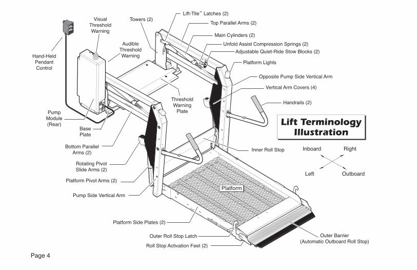
Lift TerminologyIllustration
UPDOWN32819
FOLDUNFOLD
32820®
Hand-HeldPendantControl
Top Parallel Arms (2)
Adjustable Quiet-Ride Stow Blocks (2)
Main Cylinders (2)
Vertical Arm Covers (4)
Opposite Pump Side Vertical Arm
Handrails (2)
Outer Barrier(Automatic Outboard Roll Stop)
Rotating Pivot Slide Arms (2)
Platform Pivot Arms (2)
Pump Side Vertical Arm
Bottom Parallel Arms (2)
Platform Lights
Outboard
Right
Lift-Tite™ Latches (2)
Unfold Assist Compression Springs (2)
Outer Roll Stop Latch
Platform Side Plates (2)
Platform
Left
Inboard
Towers (2)
ThresholdWarning
Plate
AudibleThresholdWarning
Visual ThresholdWarning
Inner Roll Stop
PumpModule(Rear)
BasePlate
Roll Stop Activation Feet (2)

Page 5
Lift Terminology
Introduction:
Braun NCL Century Series lifts are ADA compliant and com-ply fully with National Highway
NCL is commercial oriented (intended for operation by an attendant).
Lift models vary per size (lift model numbers indicate lift dimensions). NCL Series lift models can be equipped with left or right side pump modules as needed. A left side pump-equipped lift model is depicted in the Lift Terminology Illustra-tion (NCL917IB). Right side pump lift models are a mirrored image of rear pump models
(pump module located on op-posite end of base plate).
Refer to the Lift Terminology
lift components.
Lift operation procedures are identical for all NCL Series lift models. The operating instructions contained in this manual and appearing on lift-posted operating instructions decals address the lift control switches and the correspond-ing lift functions. Instruc-tions are provided for manual operation of the lift in event of power or equipment failure.
Terminology: Become famil-iar with the terminology that will be used throughout this manual. Become familiar with
-ponents and their functions.Contact your lift sales repre-sentative or call The Braun Corporation at 1-800-THELIFT® if any of this information is not fully understood.
Direction: The terms "left," "right," "inboard," and "out-board" will be used throughout this manual to indicate direc-tion (as viewed from outside the vehicle looking directly at the lift). Refer to the Lift Termi-
-

Page 6
Lift TerminologyLift Terminology
lift function labels illuminate to identify the function(s).
Lift Frame: The lift frame con-sists of the base plate, threshold warning plate, towers, parallel arms, vertical arms, platform pivot arms and handrails. Two main hydraulic cylinders are housed in the parallel arms.The electrical/hydraulic powered lift frame components mechani-cally unfold, lower, raise and fold the lift platform assembly.
Lift-Tite™ Latches: The spring-loaded latches prevent the platform from unfolding from the stowed position in the event of platform drift. Further details regarding Lift-Tite™ latches are provided on pages 16 and 17.
Outer Barrier: The spring-loaded automatic outer barrier (outboard roll stop) provides a ramp for wheelchair loading and unload-ing at ground level. Photos and further details regarding the outer barrier are provided in the Opera-tion Notes and Details section (pages 19-21).
Inner Roll Stop and Bridge Plate (IB): NCL Series lift models are equipped with an automatic inboard roll stop that also serves as the bridge plate. The bridge plate bridges the gap between the lift platform and the vehicle
plate automatically rotates from the horizontal position to the verti-cal position as the lift lowers and raises.
Lift Components
Refer to the Lift Terminology Il-lustration on page 4.
Pump Module: The lift-mounted pump module consists of the hydraulic pump, the manual hand pump, the electronic control board and electrical components that power the lift electric/hydrau-lic systems.
Hand-held Pendant Control:The hand-held attendant's pen-dant control is connected to the pump module. The hand-held pendant is equipped with four push button switches, (UNFOLD, FOLD, DOWN, and UP). The momentary switches activate the automatic lift functions. The

Page 7
Lift Terminology
The inner roll stop and outer barrier sense weight to prohibit lift operation. The lift will not function if the inner roll stop or outer barrier are occupied. The lift platform cannot be folded (stowed) if occupied.
The inner roll stop features a locking mechanism that prohibits the platform from lowering if the lock does not engage. The lift platform cannot be raised more than 3" above ground level un-less the outer barrier is in the vertical position.
Further details regarding the automatic mechanical inboard roll stop are provided on pages 18 and 19.
Vehicle and Lift Interlocks
Braun Corporation NCL Se-ries lifts comply fully with all NHTSA vehicle and lift inter-
movement is prohibited unless the lift is fully stowed and the lift will not function unless the vehicle is parked and secured.
The NCL features a visible and audible threshold warn-ing system that will activate if the threshold area is occupied when the platform is one inch

Page 8
Lift Terminology
F. FOLD (In) - Platform Fold:Fold is the action of the platform
level (horizontal) position to fully-stowed (vertical) position when the FOLD switch is pressed.
Stowed Position: The lift is stowed when the lift platform has been fully raised and folded fully (vertical position).
Floor Level: Floor level is the position (height) the platform as-sembly reaches in order for the wheelchair passenger to enter and exit the vehicle (fully raised). The platform automatically stops
the stowed position and when raising from ground level.
Lift Actions and Functions
DEPLOY (A-C)
A. UNFOLD (Out) - Platform Unfold: Unfold is the action of the platform rotating out and down from the fully-stowed
(horizontal) position when the UNFOLD switch is pressed.
B. DOWN - Platform Lower:Down is the action of the platform
to fully-lowered (ground level) position when the DOWN switch is pressed.
C. DOWN - Outer Barrier Unfold (Deploy) - When the platform reaches the fully-low-ered (ground) position and the
DOWN switch is continued to be pressed, the outer barrier rotates downward from vertical position to ramp position.
STOW (D-F)
D. UP - Platform Raise: Up is the action of the platform raising
(fully-raised) position when the UP switch is pressed. When the lift is fully lowered, pressing the
-form.
E. UP - Outer Barrier Fold (Raise): As the platform be-gins to raise off the ground, the spring-loaded outer barrier rotates from the ramp position to vertical position.

Page 9
Safety Symbols
Lift Operation Safety
SAFETY FIRST! Know That....
C CAUTION
This symbol indicates important information regarding how to avoid a hazardous situation that could result in minor per-sonal injury or prop-erty damage.
Asupplements (if included), is pro-vided for your safety. Familiarity with proper operation instructions as well as proper maintenance procedures are necessary to en-sure safe, troublefree operation.Safety precautions are provided to identify potentially hazardous situations and provide instruction on how to avoid them.
All information contained in this manual and B WARNING
This symbol indicates important safety information regarding a potentially hazard-ous situation that could result in serious bodily injury and/or property damage.
D Note:
These symbols will appear throughout this manual as well as on the labels posted on your lift. Recognizethe seriousness of this information.

Page 10
Lift Operation Safety Precautions
WARNING
If the lift operating instructions, manual operating instructions and/or lift operation safety precautions are not fully understood, contact The Braun Corporation immedi-ately. Failure to do so may result in serious bodily injury and/or property damage.
Read manual and supplement(s) before operating lift.Read and become familiar with all safety precautions, pre-lift operation notes and details, operating instructions and manual operating instructions before operating the lift. Note: Wheelchair passengers and all transit agency personnel (drivers and wheelchair lift attendants) must read and become familiar with the contents of this manual and supplement(s) before operation.
Load and unload on level surface only.
Engage vehicle parking brake before operating lift.
Provide adequate clearance outside the vehicle to accom-modate the lift before opening lift door(s) or operating lift.
WARNING
Lift Operation Safety
WARNING
WARNING
WARNING
Inspect lift before operation. Do not operate lift if you suspect lift damage, wear or any abnormal condition.
Keep operator and bystanders clear of area in which the lift operates.WARNING
WARNING
Page 11
Whenever a wheelchair passenger (or standee) is on the platform, the:• Passenger must be positioned fully inside yellow boundaries• Wheelchair brakes must be locked• Inner roll stop and outer barrier must be up (vertical)• Outer barrier latches must be fully engaged• Passenger should grip both handrails (if able).
Do not overload or abuse. The load rating applies to both the raising and lowering func-tions - continuous lifting capacity is 800 lbs.
Discontinue lift use immediately if any lift or vehicle interlock does not operate properly.
Do not operate or board the lift if you or your lift operator are intoxicated.
Do not raise front wheelchair wheels (pull wheelie) when loading (boarding) the platform.
Open lift door(s) fully and secure before operating lift.
Position and secure (buckle, engage, fasten, etc.) the wheelchair-equipped occupant seat belt (torso restraint) before loading onto the wheelchair lift platform.
WARNING
WARNING
WARNING
WARNING
WARNING
WARNING
WARNING
WARNING
Lift Operation Safety

Page 12
Lift Operation Safety
Lift attendants must ensure that lift occupants keep hands, arms and all other body parts within the lift occupant area and clear of moving parts.
height) when loading or unloading in and out of vehicle.
Do not use platform inner roll stop or outer barrier as a brake. Stop and brake wheelchair when loading onto the platform (manually stop and brake manual wheelchairs — stop pow-ered wheelchairs with the wheelchair controls).
Turn powered (electric) wheelchairs off when on lift platform.
Press the DOWN switch until the entire platform rests on ground level (lowered fully) and the outer barrier is fully unfolded (ramp position) before loading or unloading a pas-senger at ground level.
WARNING
Lift Operation Safety Precautions (continued)
WARNING
If the lift operating instructions, manual operating instructions and/or lift operation safety precautions are not fully understood, contact The Braun Corporation immedi-ately. Failure to do so may result in serious bodily injury and/or property damage.
WARNING
WARNING
WARNING
WARNING
WARNING
Outer barrier must be fully unfolded (ramp position) until front and rear wheelchair wheels cross roll stop when loading or unloading at ground level.

Page 13
Lift Operation Safety
WARNING Accidental activation of control switch(es) may cause unintended operation(s).
Replace missing, worn or illegible decals.
Keep owner’s (operator's) manual in lift-mounted manual storage pouch at all times.
Never modify (alter) a Braun Corporation lift.
Do not use accessory devices not authorized by The Braun Corporation.
Do not remove any guards or covers.
Keep clear of any hydraulic leak.
Failure to follow these safety precautions may result in serious bodily injury and/or prop-erty damage.
WARNING
WARNING
WARNING
WARNING
WARNING
WARNING
WARNING
WARNING

Page 14
Operation Notes and Details
NCL Series “Public Use” lift mod-
operated by an attendant. The Lift Operating Instructions contained in this manual and posted on the lift provide instructions for op-eration of the lift only. Read and become familiar with all lift opera-tion safety precautions, opera-tion notes and details, operating instructions and manual operating instructions before attempting lift operation procedures.
Lift Access Doors and Inter-locks: Attendants must become familiar with the vehicle lift access door system and vehicle interlock system(s). Transit vehicles and
vary. Door securement devices (latches, hooks, cables, etc.) and procedures to operate them vary.
Instructions for operation of vehicle interlocks and door securement systems are not addressed in this manual or on lift-posted operating instructions decals due to the variety of proce-dures required for operating them. Braun Corporation NCL Series lifts comply fully with all NHTSA
-tions (detailed on pages 7 and 32). Infringement of any lift interlock will prohibit lift operation.
It is the responsibility of the lift operator (attendant) to properly open, secure and close the vehicle lift door(s), to activate the vehicle interlock(s), to load and unload the wheelchair passenger (or standee) on and off the lift platform, and to properly activate all lift functions.
WARNING
Read and become familiar with all lift operation safety precautions, opera-tion notes and details, operating instructions and manual operat-ing instructions prior to operating the lift.If this information is not fully understood, contact The Braun Corporation immedi-ately. Failure to do so may result in serious bodily injury and/or property damage.

Page 15
Operation Notes and Details
General Safety: The lift operator (attendant) and bystanders must keep clear of the area in which the lift operates and clear of all moving parts. Lift attendants
must ensure that lift occupants (passengers) keep hands, arms and all other body parts within the lift occupant area and clear of moving parts.
Control Switches
Hand-held Pendant Control:The hand-held attendant's pendant control is equipped with two momentary rocker switches (UP/FOLD and DOWN/UNFOLD). Simply press the applicable switch in the direction of the label
DOWN
UP FOLD
UNFOLD
32525
32526
Lift Power ON/OFF Switch:This switch must be in the ON position in order to activate the lift. The green Power Indicator Light mounted on top of the pump module illuminates to signal power to the lift.
to activate the corresponding lift function.
When there is power to the lift, the lift function labels illuminate to identify the function(s).
Hand-held Pendant

Page 16
Operation Notes and Details
Lift Features
Become familiar with all lift fea-tures and the proper operation of the lift components beforeattempting lift operation. Refer to the Lift Terminology Illustra-
lift components if not
Lift-Tite™ Latches: NCL Series lifts are equipped with Lift-Tite™
Latches. Lift-Tite™ Latches pre-vent the platform from unfolding from the stowed position in
clearly depicted in this section.Contact The Braun Corporation at 1-800-THE LIFT® immediately if any of this information is not understood.
EngagedLift-Tite™
Latch
Latch En-gagementPin (Roller)
WARNING
Discontinue lift use immediately if any lift component does not operate prop-erly. Failure to do so may result in serious bodily injury and/or property damage.

Page 17
Operation Notes and Details
DisengagedLift-Tite™
Latch
Latch En-gagementPin (Roller)
the event of platform drift. Due to the “all-hydraulic” operation of the dual-cylinder NCL, hy-
-tion or seepage may occur. Any of these conditions may result in platform drift (failure to hold the platform in the folded or raised position). Platform drift may occur during lift shipment and/or between extended peri-ods of non-lift use.
In the event that the platform does not unfold when the UN-FOLD switch is pressed, press the FOLD switch momentarily to disengage the Lift-Tite™ latches (platform drift has occurred).Then, press the UNFOLD switch to unfold the platform to
When manually operating a lift equipped with Lift-Tite™ latches, insert the pump handle in the pump and stroke until the plat-form folds fully (stops). Then, open the hand pump valve (turn counterclockwise) to unfold the
platform. Folding the platform
Lift-Tite™ latches will disengage properly when the release valve is opened. Manual Operating Instructions are provided on pages 33-37.

Page 18
Inner Roll Stopand Bridge Plate
Fully Deployed(vertical)
InnerRoll Stop
The inner roll stop/bridge plate must overlap thebase plate a minimum 1/2".
Fully Unfolded(horizontal)
Inner Roll Stop (bridging position)
Lift Features (continued)
Operation Notes and Details
Inner Roll Stop and Bridge Plate: NCL Series lift models are equipped with an automatic inner roll stop that also serves as the bridge plate (inner roll stop photos below).
When the UNFOLD switch is pressed and the platform unfolds
this mechanical roll stop/bridge plate is automatically deployed to the bridging (horizontal) position to provide a bridge plate between the platform and the lift base plate
of the bridge plate rests on the threshold warning plate (base plate).
The roll stop/bridge plate auto-matically folds (rotates) to the vertical (roll stop) position when the platform lowers to the ground (DOWN switch is pressed).

Page 19
Operation Notes and Details
As the UP switch is pressed and the platform raises from ground level, the inner roll stop automati-cally unfolds (rotates) to the hori-zontal (bridging) position when it
roll stop must overlap the lift base plate a minimum 1/2".
When the FOLD switch is pressed and the platform folds
-cal) position, the roll stop/bridge plate automatically travels in-board to the stowed position.
Interlock Features: The inner roll stop features a locking mech-anism that prohibits the platform from lowering if the lock is not engaged. The inner roll stop also senses weight to prohibit lift op-eration. The lift will not function if the inner roll stop is occupied.
Discontinue lift operation im-mediately if the inner roll stop does not operate properly.
Outer Barrier: This spring-load-ed roll stop provides a ramp for wheelchair loading and unload-
WARNING
Discontinue lift use immediately if any lift component does not operate prop-erly. Failure to do so may result in serious bodily injury and/or property damage.
ing at ground level (see photos on following page). When the platform lowers fully to ground level, the roll stop activation feet automatically unfold (rotate) the barrier to the ramp position (fully unfolded). The two activa-tion feet (one at each end of the barrier) ensure barrier operation on an uneven surface.
Although the outer barrier is lift-powered, the activation of the barrier is controlled by the lift operator (attendant). Press-ing the DOWN switch unfolds the barrier. The outer barrier is spring-loaded to automati-cally fold (rotate) to the vertical position when the UP switch is pressed. As the activation feet lift off the ground, the torsion
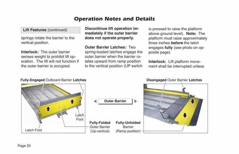
Page 20
Fully-FoldedOuter Barrier (Up-vertical)
Operation Notes and Details
Lift Features (continued)
springs rotate the barrier to the vertical position.
Interlock: The outer barrier senses weight to prohibit lift op-eration. The lift will not function if the outer barrier is occupied.
Discontinue lift operation im-mediately if the outer barrier does not operate properly.
Outer Barrier Latches: Two spring-loaded latches engage the outer barrier when the barrier ro-tates upward from ramp position to the vertical position (UP switch
is pressed to raise the platform above ground level). Note: The platform must raise approximately three inches before the latch engages fully (see photo on op-posite page).
Interlock: Lift platform move-ment shall be interrupted unless
Fully-Engaged Outboard Barrier Latches
Fully-UnfoldedBarrier
(Ramp position)
Disengaged Outer Barrier Latches
Latch Foot
LatchFoot
Outer Barrier

Page 21
Operation Notes and Details
The latches disengage the bar-rier when the platform lowers fully (reaches ground level) and the latch feet contact the ground (latches raise above the barrier). Outer Barrier and Latch Op-eration: The lift attendant must press the DOWN switch to lower the platform fully to the ground.The attendant must view the platform as it lowers to be certainthe entire platform reaches and rests safely on the ground. Stop pressing the DOWN switch if any portion of the platform is obstruct-ed while descending or the entire platform does not reach ground level for any reason (contact with an obstruction, mechanical failure,
capacity, etc.).
Note: The barrier must be fully unfolded until the entire wheel-chair (or standee) has crossed the roll stop when loading or un-loading at ground level. Discon-tinue lift operation immediately if the outer barrier or latches do not operate properly.
Bridging: The NCL incorpo-rates a bridging feature. This feature stops the down travel of the platform if the outboard end of the platform contacts a raised surface (such as a curb), prevent-ing the operator from lowering the inboard end of the platform.
Handrails: Dual handrails are provided for wheelchair pas-senger (or standee) use. The handrails unfold automatically to the deployed (horizontal) position
3"
Latch Foot
Fully-EngagedOutboard Barrier Latch
Note: Platform must raise approximately three inches before latch engages fully.
the outer barrier is raised (verti-cal position) and the outer barrier latches are positively engaged.

Page 22
Operation Notes and Details
pacity of the lift. The lift attendant should not ride on the platform with the passenger.
Passenger Orientation (Board-ing Direction): Braun NCL Series wheelchair lifts accommo-date both inboard and outboard facing wheelchair passengers or standees. Inboard facing of wheelchair lift passengers is notprohibited, but outboard facing of passengers is recommendedby The Braun Corporation.
Braun NCL Series lifts permit both inboard and outboard facing of wheelchair and mobility aid us-ers and accommodate persons using walkers, crutches, canes or braces or who otherwise have
If you are an attendant operating the lift, it is your responsibility to perform safe loading and unload-ing procedures. Wheelchair lift attendants should be instructed on any special needs and/or pro-cedures required for safe trans-port of wheelchair passengers.
The lift operator and bystanders must keep clear of the area in which the lift operates. Observe your passenger at all times during lift operation.
Do not attempt to load or unload a passenger in a wheelchair or other apparatus that does not
exceed the 800 pound load ca-
Lift Passengers
when the lift unfolds and automat-ically fold to the stowed (vertical) position when the platform folds.
If able, passengers should grip both handrails when on the lift platform. Discontinue lift opera-tion immediately if the hand-rails do not operate properly.
Lift Features (continued)

Page 23
Standees: Lift Operating Instruc-tions apply to wheelchair pas-sengers and standees. Standees should stand in the center of the platform (fully inside the yellow boundaries) and grip both hand-rails (if able) when on platform.
Yellow Boundaries: The pas-senger must be positioned in the center of the platform to pre-vent side-to-side load imbalance. The lift attendant (operator) should not ride on the platform with the passenger.
Yellow platform loading boundar-
manner. The yellow powder-coated inner roll stop and outer barrier identify the inboard and outboard ends of the platform. A
Operation Notes and Details
yellow powder-coated guard is located on the pump-side platform side plate. A yellow boundary
-posite platform side plate. Yellow plastic caps are placed on the dual handrails.
The threshold warning plate is powder-coated yellow to iden-tify the platform threshold area.Interlock: A visible and audible threshold warning system will ac-tivate if the threshold area is oc-cupied when the platform is one
The attendant must always be certain the wheelchair passenger or standee is properly positioned on the platform (fully inside yel-low boundaries) and the wheel-chair brakes are locked when a
passenger is on the lift platform.The lift passenger must keep hands, arms and all other body parts within the lift occupant area and clear of all moving parts.
Vehicle (Floor Level) Loading and Unloading: The platform
and the bridge plate must be prop-erly positioned when loading or unloading passengers in or out of the vehicle. It is the responsibil-ity of the lift attendant to ensure the platform and the bridge plate are properly positioned
unloading passengers.
The wheelchair brakes must be locked, the outer barrier must be in the fully-up (vertical) position

Page 24
Operation Notes and Details
and the outer barrier latches must be fully engaged whenever a passenger is on the platform.
Do not use the outer barrier as a brake. Stop and brake the wheelchair when fully loaded on the platform. Manually stop and brake manual wheelchairs.Stop powered wheelchairs with the wheelchair controls. Turn powered (electric) wheelchairs off when on the platform.
If the outer barrier, bridge plate, handrails or any other lift compo-nent does not operate as outlined in this manual, discontinue lift use immediately and contact The Braun Corporation sales representative in your area or
Lift Passengers (continued)
call The Braun Corporation at 1-800-THE LIFT®. One of our national Product Support repre-sentatives will direct you to an authorized service technician who will inspect your lift.
WARNING
Discontinue lift use immediately if any lift component does not operate prop-erly. Failure to do so may result in serious bodily injury and/or property damage.
WARNING
Whenever a passenger is on the platform, the:• Passenger must be
positioned fully inside yellow boundaries
• Wheelchair brakes must be locked
• Inner roll stop and outer barrier must be UP
Failure to follow these rules may result in serious bodily injury and/or property damage.

Page 25
Operation Notes and Details
Wheelchair-EquippedOccupant Seat Belts
The Braun Corporation recom-mends wheelchair passengers position and buckle their wheel-
WARNING
Position and secure (buckle, engage, fasten, etc.) the wheelchair-equippedoccupant seat belt before loading onto the wheelchair lift platform. Failure to do so may result in serious bodily injury and/or property damage.
Operation Procedure Review
The Braun Corporation rec-ommends that transit agency supervisors and wheelchair lift attendants review the safety precautions and operation procedures appearing in this manual and on lift-posted decals with your wheelchair lift sales representative (dealer), beforeattempting lift operation.
Any questions or concerns can be answered by the sales repre-sentative at that time. Operate the lift through all functions with your sales representative on hand to ensure the proper use and operation of the wheelchair lift is understood.
chair-equipped seat belt (torso restraint) before loading onto a wheelchair lift.
Different types of disabilities require different types of wheel-chairs and different types of wheelchair-equipped occupant restraint belt systems (torso restraints). It is the responsibil-ity of the wheelchair passenger to have his or her wheelchair equipped with an occupant restraint (seat belt) under the direction of their health care professional.
Wheelchair lift attendants should be instructed on any special needs and/or procedures required for safe transport of wheelchair passengers.

Page 26
Transit agency supervisors should train and educate their lift attendants on the proper use and operation of the wheelchair lift if it is not possible for the attendants to review the safety precautions and operation pro-cedures with the wheelchair lift sales representative.
The lift operator's manual must be stored in the lift-mounted manual storage pouch at all times.
Preventive Maintenance:
Maintenance is necessary to en-sure safe and troublefree lift op-eration. General preventive lift maintenance consisting of care-ful inspections of the lift system and cleaning the lift should be
Operation Notes and Details
a part of your transit agency's daily lift service program. Simple inspections can detect potential lift operational problems.
Regular preventive maintenance will reduce potential lift opera-tion downtime and increase the service life of the lift, as well as possibly detecting potential hazards.
Exposure to harsh weather ele-ments, environmental conditions, or heavy usage may require more frequent maintenance and lubrication procedures.
Preventive maintenance vi-sual inspections do not take the
in the Maintenance and Lubrica-tion Schedule provided on pages
WARNING
41-49 of this manual. Refer to the Maintenance and Lubrica-tion section for further details.
Maintenance and lubrication procedures must be performed by authorized service
in this manual. Failure to do so may result in serious bodily injury and/or property damage.

Page 27
WARNING
Whenever a passenger is on the platform, the:• Passenger must be
positioned fully inside yellow boundaries
• Wheelchair brakes must be locked
• Inner roll stop and outer barrier must be UP
Failure to follow these rules may result in serious bodily injury and/or property damage.
WARNING
Read and become familiar with all lift operation safety precautions, opera-tion notes and details, operating instructions and manual operat-ing instructions prior to operating the lift.If this information is not fully understood, contact The Braun Corporation immedi-ately. Failure to do so may result in serious bodily injury and/or property damage.
Lift Operating Instructions
Before lift operation, park the ve-hicle on a level surface, away from
transmission in "Park" and engage the parking brake.
Lift Operating Instructions photos depict lift model NCL917IB. In-structions and procedures are applicable for all NCL Series lift models. Lift-posted Warnings and Lift Operating Instructions de-cal 30695 provides lift operating instructions. Replace any missing, worn or illegible decals.
If your lift does not function as in-tended or an audible warning signal is activated, review the NHTSA Op-erations Checklist on page 32. Fol-low the Manual Operating Instruc-tions on pages 33-37 in the event of a power or equipment failure.

Page 28
Lift Operating Instructions
Open Door(s) and Secure
To Unfold Platform:
Stand clear and press the UN-FOLD switch until the platform stops (reaches - unfoldsfully). Release switch.
Note: In event platform does not unfold, press FOLD switch to release Lift-Tite™ latches.
To Unload Passenger:
1. Read Note below! Load passen-ger onto platform and lock wheel-chair brakes.
Note: Passenger must be posi-tioned fully inside yellow bound-aries, outer barrier must be UP and outer barrier latches must be engaged.
DOWN
UP FOLD
UNFOLD
32525
32526

Page 29
D
Lift Operating Instructions
To Unload Passenger (continued):
2. Press DOWN switch until the en-tire platform reaches ground level (see Photo B) and the outer barrier unfolds fully (ramp position). See Photo C. Release switch.
3. Unlock wheelchair brakes and un-load passenger from platform.
Note: Outer barrier must be fullyunfolded (ramp position) until the entire wheelchair (or standee) has crossed the outer barrier. See Photos E and F on page 30 also.
C
BA
DOWN
UP FOLD
UNFOLD
32525
32526

Page 30
FE
H
G
Lift Operating Instructions
To Load Passenger:
1. Read Notes below! Load passen-ger onto platform and lock wheel-chair brakes. See Photo G.
Note: Outer barrier must be fullyunfolded (ramp position) until the entire wheelchair (or standee) has crossed the outer barrier. See Photos E and F.
Note: Passenger must be posi-tioned fully inside yellow bound-aries.

Page 31
J
L
Lift Operating Instructions
To Load Passenger (continued):
2. Press UP switch (Photo I) to fold outer barrier UP fully (vertical - see Photo H), and raise the platform to
. See Photo J. Release switch.
3. Unlock wheelchair brakes and unload passenger from platform.
To Fold Platform:
Press FOLD switch until platform stops (fully folded). See Photos K and L. Release switch.
Close Door(s)
I
K
DOWN
UP FOLD
UNFOLD
32525
32526
DOWN
UP FOLD
UNFOLD
32525
32526
Page 32
NHTSA Operations Checklist
WARNING
Discontinue lift use immediately if any lift or vehicle interlock does not operate properly. Failure to so so may result in serious bodily injury and/or property damage.
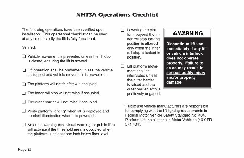
Vehicle movement is prevented unless the lift door is closed, ensuring the lift is stowed.
Lift operation shall be prevented unless the vehicle is stopped and vehicle movement is prevented.
The platform will not fold/stow if occupied.
The inner roll stop will not raise if occupied.
The outer barrier will not raise if occupied.
Verify platform lighting* when lift is deployed and pendant illumination when it is powered.
An audio warning (and visual warning for public lifts) will activate if the threshold area is occupied when
installation. This operational checklist can be used at any time to verify the lift is fully functional.
*Public use vehicle manufacturers are responsible for complying with the lift lighting requirements in Federal Motor Vehicle Safety Standard No. 404, Platform Lift Installations in Motor Vehicles (49 CFR 571.404).
Lowering the plat-form beyond the in-ner roll stop locking position is allowed only when the inner roll stop is locked in position.
Lift platform move-ment shall be interrupted unless the outer barrier is raised and the outer barrier latch is positevely engaged.

Page 33
Manual Operating Instructions
If you experience power or equipment failure, refer to the Manual Operating Instructions to operate the lift. Instructions and photos are provided for all
steps that differ from standard lift operation procedures. The Manual Instructions decal (post-ed inside pump cover) provides manual operating instructions
also. Note: A right side pump lift model is depicted in the photos.Left side pump applications are a mirrored image. Refer to the Lift Operating Instructions for all
HandPump
Handle
Turn wing 1/4 turn.Rotate top clip to access handle.Pump
Cover
Lock
Unlock

Page 34
Manual Operating Instructions
Release Valve
maximum30 inch lbs
minimum15 inch lbs
seats(stops)
OP
EN
CLOS
Eapproximate
1/16" intervals
Valve Tightening
Once valve seats (stops), tighten 15to 30 inch pounds as shown.
Release Valve
Note: Close backup pump release valve securely before operating electric pump.
A
normal lift operation procedures (such as loading and unloading passengers). Follow all Lift Op-eration Safety Precautions!
Remove the pump cover to gain access to the pump handle and the hand pump. See photos on page 33. To remove the pump cover, turn the wing nut located
on top 1/4 turn and lift the pump cover off. The pump handle is inside this cover secured by two clips. Rotate the top clip to remove the pump handle.
Hand Pump

Page 35
Open(Down)
Close(Up/Stop)
Manual Operating Instructions
Remove pump cover to access hand pump and pump handle as outlined on page 33. Refer to release valve photos and illustra-tion on page 34.
To Unfold Platform (Out):
Place slotted end of pump handle onto backup pump release valve and turn counterclockwise (open 1/2 turn only) until the platform reaches ground level and roll stop unfolds.
B C
Using hand pump handle (Photo B):
1. Close hand pump valve (place slotted end of pump handle onto backup pump release valve and turn clockwise).
2. Insert handle in pump and stroke until platform folds fully (stops).
3. Open hand pump valve (turn counterclockwise) until platform
Open 1/2 turn only.
4. Close hand pump valve (turn clockwise).
Note: Valve must be tight, but donot overtighten.
StrokingHandPump
Down (To Lower):

Page 36
StrokingHandPump
Up (To Raise):
Open(Down)
Close(Up/Stop)
Manual Operating Instructions
E
Using hand pump handle:
1. Place slotted end of pump han-dle onto backup pump release valve and turn clockwise to close securely. See Photo D.
Note: Valve must be tight, but do not overtighten.
2. Insert handle into backup pump and stroke until platform reaches (see Photo E).
To Fold Platform (In):
Insert handle into backup pump and stroke until platform stops(folds fully). See Photo E.
D
Remove pump cover to access hand pump and pump handle as outlined on page 33. Refer to release valve photos and illustra-tion on page 34.
Note: Close backup pump release valve securely beforeoperating electric pump.
Store pump handle and install pump cover as outlined on page 37.

Page 37
Manual Operating Instructions
To Store Pump Handle:
1. Insert bottom of handle behind bottom clip. See page 33.
2. Rotate top clip to secure (lock) handle.
To Install Pump Cover:
1. Position cover over module back cover and red warning light. See Photo F.
2. Align outside cover lip with bottom cover offset and insert outside cover. See Photo G.
3. Insert wing stud and rotate 1/4turn to lock cover. See Photo H.
Align and insert bottom of cover.
F HG
Lock
Unlock
Position cover over red light.
Page 38
29813
29813
WARNING
LIFT OPERATINGINSTRUCTIONS
OPEN DOOR(S) AND SECURE
TO UNFOLD PLATFORM:
Stand clear and press UNFOLD switch until platform stops (reaches floor level).
Note: In event platform does not unfold, press FOLD switch to release Lift-Tite™ latches.
TO UNLOAD PASSENGER:
1. Load passenger onto platform and lock wheelchair brakes.2. Press DOWN switch until entire platform reaches ground level and outer barrier unfolds fully.3. Unlock wheelchair brakes and unload passenger from platform.
TO LOAD PASSENGER:
1. Load passenger onto platform and lock wheelchair brakes.2. Press UP switch to fold outer barrier up and raise platform to floor level.3. Unlock wheelchair brakes and unload passenger from platform.
TO FOLD PLATFORM:
Press FOLD switch until platform stops. Release switch.
CLOSE DOOR(S)
DOT — Public Use Lift30695
Whenever a wheelchair passenger is on the platform, the: • Passenger must be positioned fully inside yellow boundaries • Wheelchair brakes must be locked • Inner roll stop and outer barrier must be upFailure to follow these rules may result in serious bodily injury and/or property damage.
• Read manual before operating lift.• Load and unload on level surface only.• Engage vehicle parking brake before operating lift.• Provide adequate clearance outside of vehicle to accommodate lift.• Do not operate lift if you suspect lift damage, wear or any abnormal condition.• Keep operator and bystanders clear of area in which lift operates.
Replace missing, worn or illegible decals.Failure to do so may result in serious bodily injury and/or property damage.
WARNING
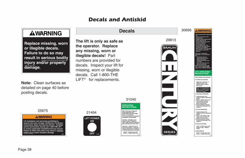
Decals and Antiskid
Decals
The lift is only as safe as the operator. Replace any missing, worn or illegible decals! Part numbers are provided for decals. Inspect your lift for missing, worn or illegible decals. Call 1-800-THELIFT® for replacements.
21494
30695
Note: Clean surfaces as detailed on page 40 before posting decals.
25675
WARNINGLift installation and servicing prohibited by anyone who has not been certified by The Braun Corporation Sales and Service School. Certified service technicians should call 1-800-THE LIFT to receive applicable installation/service manual.Failure to follow this policy may result in serious bodily injury and/or property damage.
25675 21494
LIFT POWERON
OFF
OPERATINGINSTRUCTIONS
Read warnings and operate lift as outlined on LIFT OPERATING INSTRUCTIONS decal. Lift operating instructions apply to wheelchair passengers and standees.
Standees: Standees must stand at center of platform (fully inside yellow boundaries), grip handrails and lower head.
Interlocks: Interlocks vary in type and operation. Interlocks must be operational as defined in NHTSA Operations Checklist.
DOT — Public Use Lift31045
31045

Page 39
29052
2905
2
31412
OP
EN
CLOS
E
OPEN
VALVE
CLOSE
UN
LO
CKLOCK
TO REMOVE PUMP HANDLE:
1. Rotate top clip.
Using hand pump handle:
TO UNFOLD PLATFORM (OUT):
1. Close hand pump valve (turn clockwise). 2. Insert handle in pump and stroke until platform folds fully (stops). 3. Open hand pump valve (turn counterclockwise) until platform reaches floor level. Open 1/2 turn only. 4. Close hand pump valve (turn clockwise).
DOWN (TO LOWER):
Open hand pump valve (turn counterclockwise). Open 1/2 turn only.
UP (TO RAISE):
1. Close hand pump valve (turn clockwise). 2. Insert handle in pump and stroke until platform reaches floor level.
TO FOLD PLATFORM (IN):
Insert handle in pump and stroke.
Note: Close valve before operating electric pump.
TO STORE PUMP HANDLE:
1. Insert bottom of handle behind bottom clip. 2. Rotate clip to lock.
DOT — Public Use Lift
31412
MANUAL OPERATION
Decals and Antiskid
32410
57 – Outer barrier is not up and latched and ground detect switch did not deactivate (Century and Vista only)
58 – Outer barrier is not up and latched and the platform is 3" above the ground
59 – Outer barrier is not up after pausing platform travel
60 – The kickout gas springs are worn, replace before using
75 – Low voltage detected; must turn off power switch to reset LCD
77 – Vehicle secure interlock has not been activated
90 – Position will be set if you keep holding the button until it beeps
91 – Position is out of a predetermined acceptable range of floor position
92 – Bridge switch is not made, needs adjusting93 – Inner rollstop occupied switch is not made,
position needs to be moved or switch should be adjusted
94 – Outer barrier is not made, fix and try again95 – Outer barrier latch is not made (check for
jumper on Century and Vista lifts, check latch on Millennium lifts)
99 – Controller program is not valid; replace controller
Flashing Numbers
Flashing 65 – Unfold button is pressedFlashing 66 – Fold button is pressedFlashing 67 – Down button is pressedFlashing 68 – Up button is pressedFlashing 69 – Bridge switch is activatedFlashing 70 – Outer barrier latch switch is
activatedFlashing 71 – Ground detect switch is activatedFlashing 72 – Outer barrier up switch is activatedFlashing 73 – Inner rollstop up switch is activatedFlashing 74 – Inner rollstop occupied switch is
activatedFlashing 76 – Outboard barrier occupied switch
is activatedFlashing 78 – Threshold tape switch “A” is
activatedFlashing 79 – Threshold tape switch “B” is
activatedFlashing 80 – Position set button is pressedFlashing 81 – Single function UP / FOLD /
CLOSE button is pressedFlashing 82 – Single function OPEN / UNFOLD /
DOWN button is pressedFlashing 87 – CLOSE button is pressedFlashing 88 – OPEN button is pressedFlashing 89 – Door full open switch is activated
(or jumper is installed on control board)
LCD Lift Codes
Listed below are codes that the lift controller outputs during lift operation. The codes will be displayed on an LCD screen located on the lift control board inside the pump module.
Non-Flashing Numbers
01 – Platform stowed02 – Platform unfolding03 – Platform unfolding paused04 – Platform at floor level05 – Platform beginning to lower06 – Platform lowering (threshold cannot be
occupied from this point down)07 – Outer barrier moving to horizontal
position08 – Platform at ground level09 – Outer barrier moving to vertical position10 – Platform raising11 – Platform raising paused at floor12 – Platform folding (limited pressure)13 – Platform folding (full pressure)14 – Timed fold (cinching lift tite) or (anti-rattle
state)15 – Platform folding stopped16 – Paused fold 17 – Platform between ground and 3" above
ground18 – Platform above 3"19 – Outer barrier moving to horizontal
postion20 – The doors are not fully opened (only
applicable when door operators are installed)
21 – The doors are opening (only applicable when door operators are installed)
22 – The doors are closing (only applicable when door operators are installed)
28 – Illegal function/not defined29 – Interlock fault not recognized (or has
been cleared but a motion button is still pressed)
30 – Platform location unknown31 – Platform location transition state;
attempting to locate position35 – Two or more motion buttons are being
pressed36 – The retention belt cannot be buckled
while trying to fold or unfold37 – Motion button being pressed is not a
valid motion50 – Outer barrier is not up above inboard
barrier locked position51 – Threshold is occupied when platform is
1" or more below floor level52 – Inner rollstop is not up and locked below
inner rollstop locked position53 – Inner rollstop occupied sensor is not
activated between floor and inner rollstop up position
54 – Outer barrier is occupied before it is up55 – Outer barrier is not latched when above
the inner rollstop locked position (Millennium only)
56 – Outer barrier is not up and latched and bridge switch did not deactivate
32410
32201
32201
PLATFORM FOLDRELIEF VALVEADJUSTMENT
Platform Fold Relief Valve: See service manual for adjustmentprocedure.
30787
Improper handling and/or servicing procedures mayresult inelectrostaticdischarge (ESD)!ESD may result inelectronic moduledamage.
C A U T I O N
30787
Decals
31132WARNING
3113
2

Page 40
Decals and Antiskid
Antiskid
Inspect your lift for any miss-ing or worn antiskid. Order as needed. Note: Clean surfaces with isopropyl alco-hol before decal or antiskid application. Use a clean cloth or paper towels. Donot use oily shop rags. Wipe surface free of residue with dry portion of cleaning cloth.
Replace missing or worn antiskid.Failure to do so may result in serious bodily injury and/or property damage.
WARNING
29051
MANUAL OPERATION
Turn wing 1/4 turn for hand pump access.
29051
Lock
Unlock
1" Wide Yellow Boundary Tape 30236R
(order by the inch as needed)
WARNINGContact The BraunCorporation beforeadjusting hydraulicpressure relief valve. Failure to do so may result in serious bodily injury and/orproperty damage.
22249
25652
18229
25652
MADE INAMERICA
Quality inspected
By: 18229
22249
Decals
2" x 12" Black #24172-BK
2" x 12" Yellow #24172-YL
3" x 8" Black #31188-BK
3" x 12" Black #24173-BK
3" x 12" Yellow #24173-YL
6" x 12" Black #24174-BK
6" x 12" Yellow #24174-YL
Size Color Part No.Available Antiskid

Page 41
Maintenance and Lubrication
Proper maintenance is necessary to ensure safe, troublefree operation. Inspecting the lift for any wear, damage or other abnormal conditions should be a part of all transit agencies's daily service program. Simple inspections can detect potential problems.
The maintenance and lubrication procedures must be per-
formed by a Braun authorized service represen-tative at the scheduled intervals according to the number of cycles.
NCL Series lifts are equipped with hardened pins and self-lubricating bushings to decrease wear, provide smooth operation and extend the service life of the lift.
When servicing the lift at the recommended intervals, inspection and lubrication procedures
repeated. Clean the components and the sur-rounding area before applying lubricants.
LPS2 General Purpose Penetrating Oil is recommended where Light Oil is called out. Use of improper lubricants can attract dirt or other contaminants which could result in wear or damage to the components.Platform components exposed to contami-nants when lowered to the ground may require extra attention.
Lift components requiring grease are lubricated during assembly procedures. When these compo-nents are replaced, grease must be applied during
available from The Braun Corporation (part num-bers provided on page 42).
Maintenance and lu-brication procedures must be performed
authorized service technician.Failure to do so may result in serious bodily injury and/or property damage.
WARNING
Page 42
Maintenance and LubricationAll listed inspection, lubrication and maintenance procedures should be repeated at “750 cycle” intervals following the scheduled “4500 Cycles” maintenance. These intervals are a general guideline for scheduling maintenance procedures and will vary according to lift use and conditions. Lifts exposed to severe conditions (weather, environment, contamination, heavy usage, etc.) may require inspection and maintenance proce-
Maintenance Indicator: The Lift Ready green LED mounted on top of the pump cover will begin to blink after every 750 cycles. The blinking LED will not affect the functions of the lift, but is a
reminder to complete necessary maintenance and lubrication. Once the lift has been serviced, fully stow the lift. Once stowed, press the UP button on the hand pendant and the Floor Level Set but-ton on the back side of the pump cover until the Lift Ready green LED stops blinking.
Discontinue lift use immediately if maintenance and lubrication procedures are not properly per-formed, or if there is any sign of wear, damage or improper operation. Contact your sales represen-tative or call The Braun Corporation at 1-800-THELIFT®. One of our national Product Support repre-sentatives will direct you to an authorized service technician who will inspect your lift.
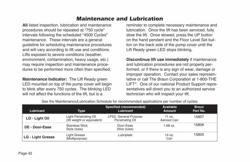
Lubricant Type Lubricant Amount Part No.
See the Maintenance/Lubrication Schedule for recommended applications per number of cycles.
LO - Light Oil
DE - Door-Ease
Light Grease Lubriplate 14 oz.(Multipurpose) CanLG - Light Grease
15807
15806
15805
Light Penetrating Oil LPS2, General Purpose 11 oz.(30 weight or equivalent) Penetrating Oil Aerosol Can
Stainless Stick Door-Ease 1.68 oz.Style (tube) Stick (tube)

Page 43
UPDOWN32819
FOLDUNFOLD
32820®
Handrail Pivot Pins (2)LO
Parallel Arm Pivot Pins (8)LO
Lift-Tite Latches (Tower Pivot Points - 2)
LOLift-Tite Latch Dampening Spring
(2 springs - 4 Points) LO
Parallel ArmPivot Pins (8)
LO
Inner Roll Stop (IB) Pivot Points LO
Outer Barrier Hinge Pivot Points (2)
LO
Platform Pivot Pin (2 Points) LO
Platform Fold Axles (2) LO
Rotating Pivot Slide Arm UHMW Slide (1) DE
Rotating Pivot Slide Arm Pivot Pins LO
Lift-Tite Latch Roller Assemblies (2) LO
Rotating Pivot Slide Arm UHMW Bearings (2) DE Lubrication
Diagram
Outer Barrier Latch Lever LO
Outer Barrier Latch LO

Page 44
Maintenance and Lubrication Schedule
750Cycles
Outer barrier hinge pivot points (2)
Outer barrier latch (pivot/slide points)
Outer barrier latch lever pivot points
Lift-Tite™ latches (tower pivot points - 2)
Lift-Tite™ latch gas (dampening) spring pivotpoints (2 springs - 4 points)
Inspect Lift-Tite™ latches and gas springs for wear or damage (bent, deformed or misaligned), posi-tive securement (external snap rings) and proper operation
Inspect outer barrier for proper operation Inspect outer barrier latch for proper operation, positive securement, and detached or missing spring
Inspect lift for wear, damage or any abnormal condition
Inspect lift for rattles
Apply Light Oil - See Lubrication Diagram
Apply Light Oil - See Lubrication Diagram
Apply Light Oil - See Lubrication Diagram
Apply Light Oil - See Lubrication Diagram
Apply Light Oil - See Lubrication Diagram
Resecure, replace defective parts or otherwise correct as needed. Note: Apply Light Grease to Lift-Tite™ latch tower pivot point if replacing latch.
Correct or replace defective parts.
Correct or replace defective parts and/or relubri-cate. See Lubrication Diagram
Correct as needed.
Correct as needed.

Page 45
Apply Light Oil - See Lubrication Diagram
Apply Light Oil - See Lubrication Diagram
Apply Light Oil - See Lubrication Diagram
Apply Light Oil - See Lubrication Diagram
Apply Light Oil - See Lubrication Diagram
Apply Light Oil - See Lubrication Diagram
Apply Light Oil - See Lubrication Diagram
Apply Light Oil - See Lubrication Diagram
Correct, replace defective parts and/or relubri-cate.
Resecure, replace or correct as needed. See Platform Angle Instructions and Microswitch Adjustment Instructions.
Maintenance and Lubrication Schedule
Perform all procedures listed in previous section also
Platform pivot pin bearings (2)
Platform fold axles (2)
Inner roll stop (IB) lever bearings (2)
Inner roll stop (IB) lever slot (2)
Rotating pivot slide arm pivot pins (2)
Parallel arm pivot bearings (16)
Handrail pivot pin bearings (4)
Hydraulic cylinder bushings (8)
Inspect Lift-Tite™ latch rollers for wear or damage, positive securement and proper operation (2)
Inspect inner roll stop (IB) for:• Wear or damage• Proper operation. Roll stop should just rest on top surface of the base plate.
• Positive securement (both ends)
1500Cycles
continued

Page 46
Maintenance and Lubrication Schedule
Perform all procedures listed in previous section also
Inspect handrail components for wear or damage, and for proper operation
Inspect microswitches for securement and proper adjustment. Make sure lift operates smoothly
Inspect external snap rings:• Handrail pivot pins (2 per pin)• Platform slide/rotate pivot pins (2 per pin)• Platform fold axles (1 per axle)• Inner roll stop (IB) lever bracket pins (1 per pin)• Lift-Tite™ latch gas (dampening) spring (2 per
spring)
Inspect platform fold axles and bearings for wear or damage and positive securement
Replace defective parts.
Resecure, replace or adjust as needed. See Microswitch Adjustment Instructions.
Realign towers and vertical arms. Lubricate or correct as needed.
Resecure or replace if needed.
Replace defective parts and resecure as needed. Apply Light Oil.
1500Cycles
continued

Page 47
Maintenance and Lubrication Schedule
Resecure, replace or correct as needed
Use Braun 32840-QT (Exxon® Univis HVI 26) do not mix with Dextron III or other
platformlowered fully and roll stop unfolded fully. Fill
(neck).
Tighten, repair or replace if needed.
Replace if needed.
Inspect cotter pins on platform pivot pin (2)
Hydraulic Fluid (Pump) - Check level. Note: Fluid should be changed if there is visible contamination.
-
for wear, damage or leaks
Inspect parallel arms, bushings and pivot pins for visible wear or damage
4500Cycles
Perform all procedures listed in previous sections also
1500Cycles
Resecure, replace or correct as needed.Remove pump module cover and inspect:
wear or leaks • Harness cables, wires, terminals and connec-
tions for securement or damage• Control board, circuit breaker, power switch and
lights for securement or damage
continued

Page 48
Maintenance and Lubrication Schedule
Perform all procedures listed in previous section also
Tighten or replace if needed.
Replace defective parts and resecure as needed.Apply Light Grease during reassembly procedures.
Replace if needed.
Tighten, replace or correct as needed
Apply Door-Ease or replace if needed. See Lubri-cation Diagram.
Resecure or replace if needed.
Resecure, repair or replace if needed.
Inspect parallel arm pivot pin mounting bolts (8)
Inspect platform pivot pin, bushings and vertical arms for wear, damage and positive securement
Inspect upper/lower fold arms, rotating pivot slide arms, slide support arms and associated pivot pins, bushings, and bearings for visible wear or damage
Inspect gas springs (cylinders) for wear or damage, proper operation and positive securement (IB)
Inspect rotating pivot slide arm UHMW slide bear-ings (buttons - 2) and UHMW slide (1)
Inspect vertical arm plastic covers
Inspect power cable
4500Cycles
continued

Page 49
Maintenance and Lubrication Schedule
Check to see that the lift is securely anchored to the vehicle and there are no loose bolts, broken welds, or stress fractures.
Replace decals if worn, missing or illegible. Re-place antiskid if worn or missing. See Decals and Antiskid section on pages 35-37.
Mounting
Decals and Antiskid
4500Cycles
Repeat all previously listed inspection, lubrica-tion and maintenance procedures at 750 cycle intervals.
Consecutive 750 Cycle Intervals

"Providing Access to the World"®
Over 300 Braun Dealers Worldwide

Opera
tor's
Man
ual
31065 Rev. A October 200631065 Rev. A October 2006 © The Braun Corporation© The Braun Corporation
All illustrations, descriptions and specifications in this manual are based on the latest product information available at the time of publication. The Braun Corporation reserves the right to make changes at any time without notice.All illustrations, descriptions and specifications in this manual are based on the latest product information available at the time of publication. The Braun Corporation reserves the right to make changes at any time without notice.
The Braun Corporation of Winamac, Indiana, warrants its wheelchair lift against defectsin material and workmanship for up to five years*, providing the lift is installed, operated and maintained properly and in conformity with this manual. This warranty is limited to the originalpurchaser and does not cover defects in the motor vehicle on which it is installed, or defects in the lift caused by a defect in any part of the motor vehicle.
This warranty commences on the date the lift is put into service, providing the warranty registration card is completed and received by The Braun Corporation within twenty days of purchase. If no warranty card is received, the warranty will expire three years from the date of manufacture as identified on the lift serial number tag.
This warranty also covers the cost of labor for the repair or replacement of parts for three years when performed by an approved Braun Dealer. (A labor schedule determines cost allowance for repairs, which can be provided upon request by an approved Braun Dealer).
This warranty does not cover normal maintenance, service, or periodic adjustments necessitated by use or wear. The Braun Corporation will not, under any circumstances, pay for loss of use, incidental or consequential damages related to the lift, or vehicle in which it is installed.
This warranty will become null and void if the lift has been damaged through accident, misuse, or neglect, or if the lift has been altered in any respect.
* The five-year portion of this warranty covers the following lift’s power train parts:• Cable • Cylinder • Flow Control • Gear Box • Motor • Pump • Hydraulic Hose & Fittings • Solid State Controller
All remaining lift components are covered by a three-year warranty.
Century Series LiftBraun “Worry-Free”
Five-Year Limited Warranty Public U
se W
heelch
air L
ifts
Bra
un
NCL Se
ries
Bra
un
NCL Se
ries
Opera
tor's M
an
ual