operator's manual - taylor company€¦ · operator's manual model 810, 812, 820, 822,...
TRANSCRIPT

OPERATOR'SMANUAL
Model 810, 812, 820, 822, 828 SeriesAuto Lift Grills
Original Operating Instructions
073523-M9/15/10 (Original Publication)
(Updated 8/10/15)

Complete this page for quick reference when service is required:
Taylor Distributor:
Address:
Phone:
Service:
Parts:
Date of Installation:
Information found on data plate:
Model Number:
Serial Number:
Electrical Specs: Voltage Cycle
Phase
Maximum Fuse Size: Amps
Minimum Wire Ampacity: Amps
Part Number:
E 2010 Carrier Commercial Refrigeration, Inc.073523-MAny unauthorized reproduction, disclosure, or distribution of copies by any person of any portion of this work maybe a violation of Copyright Law of the United States of America and other countries, could result in the awardingof Statutory Damages of up to $250,000 (17 USC 504) for infringement, and may result in further civil and criminalpenalties. All rights reserved.
Taylor Companya division of Carrier Commercial Refrigeration, Inc.750 N. Blackhawk Blvd.Rockton, IL 61072

Table of Contents Model 810, 812, 820, 822, 828 Series
Table of Contents
Section 1 To the Installer 1. . . . . . . . . . . . . . . . . . . . . . . . . . . . . . . . . . . . . . . . . . . .
Installer Safety 1. . . . . . . . . . . . . . . . . . . . . . . . . . . . . . . . . . . . . . . . . . . . . . . . . . . . . . . .
Site Preparation 1. . . . . . . . . . . . . . . . . . . . . . . . . . . . . . . . . . . . . . . . . . . . . . . . . . . . . . .
Electrical Connections 1. . . . . . . . . . . . . . . . . . . . . . . . . . . . . . . . . . . . . . . . . . . . . . . . .
Installation 2. . . . . . . . . . . . . . . . . . . . . . . . . . . . . . . . . . . . . . . . . . . . . . . . . . . . . . . . . . .
Ventilation and Clearance 2. . . . . . . . . . . . . . . . . . . . . . . . . . . . . . . . . . . . . . . . . . . . . .
Grease Disposal Container 2. . . . . . . . . . . . . . . . . . . . . . . . . . . . . . . . . . . . . . . . . . . . .
Section 2 To the Operator 3. . . . . . . . . . . . . . . . . . . . . . . . . . . . . . . . . . . . . . . . . . .
Section 3 Safety 4. . . . . . . . . . . . . . . . . . . . . . . . . . . . . . . . . . . . . . . . . . . . . . . . . . . .
Section 4 Operator Parts Identification 6. . . . . . . . . . . . . . . . . . . . . . . . . . . . . . .
L810 / G810 Exploded View 6. . . . . . . . . . . . . . . . . . . . . . . . . . . . . . . . . . . . . . . . . . . .
L812 Exploded View 7. . . . . . . . . . . . . . . . . . . . . . . . . . . . . . . . . . . . . . . . . . . . . . . . . . .
L820 / G820 Exploded View 8. . . . . . . . . . . . . . . . . . . . . . . . . . . . . . . . . . . . . . . . . . . .
L822 Exploded View 9. . . . . . . . . . . . . . . . . . . . . . . . . . . . . . . . . . . . . . . . . . . . . . . . . . .
L828 / G828 Exploded View 10. . . . . . . . . . . . . . . . . . . . . . . . . . . . . . . . . . . . . . . . . . . .
Accessories Supplied With Grill 11. . . . . . . . . . . . . . . . . . . . . . . . . . . . . . . . . . . . . . . . .
Optional Accessories Available From Local Taylor Distributor 12. . . . . . . . . . . . . . .
Section 5 Important: To the Operator 13. . . . . . . . . . . . . . . . . . . . . . . . . . . . . . . . .
Section 6 Operating Procedures 14. . . . . . . . . . . . . . . . . . . . . . . . . . . . . . . . . . . . .
Daily Opening Procedures 14. . . . . . . . . . . . . . . . . . . . . . . . . . . . . . . . . . . . . . . . . . . . . .
Loading Store Menu Items To USB 21. . . . . . . . . . . . . . . . . . . . . . . . . . . . . . . . . . . . . .
Loading Menu Items From USB 22. . . . . . . . . . . . . . . . . . . . . . . . . . . . . . . . . . . . . . . . .
Operating Procedures 24. . . . . . . . . . . . . . . . . . . . . . . . . . . . . . . . . . . . . . . . . . . . . . . . .
Daily Cleaning Procedures 28. . . . . . . . . . . . . . . . . . . . . . . . . . . . . . . . . . . . . . . . . . . . .
Model 810, 812, 820, 822, 828 Series Table of Contents
Table of Contents - Page 2
Section 7 Troubleshooting Guide 37. . . . . . . . . . . . . . . . . . . . . . . . . . . . . . . . . . . .
Section 8 Limited Warranty on Equipment 42. . . . . . . . . . . . . . . . . . . . . . . . . . . .
Section 9 Limited Warranty on Parts 45. . . . . . . . . . . . . . . . . . . . . . . . . . . . . . . . .
Note: Continuing research results in steady improvements; therefore, informationin this manual is subject to change without notice.
Note: Only instructions originating from the factory or its authorized translationrepresentative(s) are considered to be the original set of instructions.
E 2010 Carrier Commercial Refrigeration, Inc. (Original Publication)(Updated August, 2015)073523-MAny unauthorized reproduction, disclosure, or distribution of copies by any person of any portion of thiswork may be a violation of Copyright Law of the United States of America and other countries, could resultin the awarding of Statutory Damages of up to $250,000 (17 USC 504) for infringement, and may resultin further civil and criminal penalties.All rights reserved.
Taylor Companya division of Carrier Commercial Refrigeration, Inc.750 N. Blackhawk Blvd.Rockton, IL 61072

1Model 810, 812, 820, 822, 828 Series To the Installer
131205
Section 1 To the Installer
The following information has been included in themanual as safety and regulatory guidelines. Forcomplete installation instructions, please see theInstallation Checklist.
Installer Safety
In all areas of the world, equipment shouldbe installed in accordance with existing local codes.Please contact your local authorities if you have anyquestions.
Care should be taken to ensure that all basic safetypractices are followed during the installation andservicing activities related to the installation andservice of Taylor equipment.
S Only Taylor authorized service personnelshould perform installation and repairs onthe equipment.
S Authorized service personnel should consultOSHA Standard 29CFRI910.147 or theapplicable code of the local area for theindustry standards on lockout/tagoutprocedures before beginning any installationor repairs.
S Authorized service personnel must ensurethat the proper PPE is available and wornwhen required during installation andservice.
S Authorized service personnel must removeall metal jewelry, rings, and watches beforeworking on electrical equipment.
The main power supply(s) to the equipmentmust be disconnected prior to performing anyrepairs. Failure to follow this instruction may result inpersonal injury or death from electrical shock orhazardous moving parts as well as poorperformance or damage to the equipment.
Note: All repairs must be performed by anauthorized Taylor Service Technician.
This unit has many sharp edges that cancause severe injuries.
Site Preparation
Review the area where the unit will be installedbefore uncrating the unit. Make sure all possiblehazards to the user or equipment have beenaddressed. Fill out the store survey form.
Electrical Connections
The grill is supplied with one or more power cords.Check the data plate on the grill for voltage, cycle,phase and electrical specifications. Refer to thewiring diagram provided inside the protective controlpanel door at the front of the grill for proper powerconnections. The power connection(s) are locatedbehind the access line cover on the front of the grill.
In the United States, this equipment is intended tobe installed in accordance with the NationalElectrical Code (NEC), ANSI/NFPA 70-1987. Thepurpose of the NEC code is the practicalsafeguarding of persons and property from hazardsarising from the use of electricity. This code containsprovisions considered necessary for safety.Compliance therewith, and proper maintenance, willresult in an installation essentially free from hazard!
In all other areas of the world, equipment should beinstalled in accordance with the existing local codes.Please contact your local authorities.
The Proper Wire Size and Branch CircuitOvercurrent Device shall be selected according tothe data label information and in accordance withCEC Part I 2006, Section 14-100(e)(i).
FOLLOW YOUR LOCAL ELECTRICAL CODES!
2 Model 810, 812, 820, 822, 828 SeriesTo the Installer
CAUTION: THIS EQUIPMENT MUST BEPROPERLY GROUNDED! FAILURE TO DO SOCAN RESULT IN SEVERE PERSONAL INJURYFROM ELECTRICAL SHOCK!
This unit is provided with an equipotentialgrounding lug that is to be properly attached to therear of the frame by the authorized installer. Theinstallation location is marked by the equipotentialbonding symbol (5021 of IEC 60417-1) on both theremovable panel and the equipment's frame.
S Stationary appliances which are notequipped with a power cord and a plug oranother device to disconnect the appliancefrom the power source must have an all-poledisconnecting device with a contact gap ofat least 3 mm installed in the externalinstallation.
S Appliances that are permanently connectedto fixed wiring and for which leakagecurrents may exceed 10 mA, particularlywhen disconnected or not used for longperiods, or during initial installation, shallhave protective devices such as a GFI, toprotect against the leakage of current,installed by the authorized personnel to thelocal codes.
S Supply cords used with this unit shall beoil-resistant, sheathed flexible cable notlighter than ordinary polychloroprene orother equivalent syntheticelastomer-sheathed cord (Code designation60245 IEC 57) installed with the proper cordanchorage to relieve conductors from strain,including twisting, at the terminals andprotect the insulation of the conductors fromabrasion.
If the supply cord is damaged, it must bereplaced by an authorized Taylor servicetechnician in order to avoid a hazard.
Installation
WARNING: Improper installation, adjustment,alteration, service or maintenance can causeproperty damage, injury or death. Read theinstallation, operating and maintenanceinstructions thoroughly before installing orservicing this equipment.
This machine is designed for indoor use only.
DO NOT install the machine in an areawhere a water jet could be used to clean or rinse themachine. Failure to follow this instruction may resultin serious electrical shock.
This grill must be installed on a levelsurface. Failure to comply may result in personalinjury or equipment damage.
Installation of Cable Kit
If the unit is permanently connected, the Cable Kitmust be installed. Flexible conduit must be usedwhen installing the appliance.
Ventilation and Clearance
To ensure proper operation of this appliance, it mustbe installed so that the products of combustion areefficiently removed.
After set up, do not store anything on top ofthe grill. Failure to follow this instruction may resultin a fire hazard.
Grease Disposal Container
If the grill is not factory-equipped with greasedisposal containers, the store is required to provideappropriate grease disposal containers inaccordance with NSF Standard 4 requirements.

3Model 810, 812, 820, 822, 828 Series To the Operator
131205
Section 2 To the Operator
The Taylor grills included in this manual consist ofthe base model numbers 810, 812, 820, 822, and828.
Prefix letters were added to the base modelnumbers to denote minor design differences:L = Platen Length (21” / 533 mm)G = Grooved OptionThe Models 810 and 812 are 36” (914 mm) grills.The Model 810 is equipped with three upper platensand the Model 812 is equipped with two upperplatens.
The Models 820 and 822 are 24” (610 mm) grills.The Model 820 is equipped with two upper platensand the Model 822 is equipped with one upperplaten.
The Model 828 is a 12” (305 mm) grill equipped withone upper platen.
These grills are capable of cooking a variety ofproducts and feature two cooking options. Theyprovide all the features of a flat grill as well as theadvantages of two-sided cooking.
The grill you have purchased has been carefullyengineered and manufactured to providedependable operation. When properly operated andmaintained, it will produce a consistent qualityproduct. Like all mechanical products, it will requirecleaning and maintenance. A minimum amount ofcare and attention is necessary if the operatingprocedures in this manual are followed closely.
This Operator's Manual should be readbefore operating or performing any maintenance onyour equipment.
It is strongly recommended that all personnelresponsible for the equipment's operation andcleaning review these procedures for proper trainingand assurance that no misunderstandings exist.
In the event you should require technical assistance,please contact your local authorized TaylorDistributor.
Note: Your Taylor warranty is valid only if the partsare authorized Taylor parts, purchased from thelocal authorized Taylor Distributor, and only if allrequired service work is provided by an authorizedTaylor service technician. Taylor reserves the rightto deny warranty claims on units or parts ifnon-Taylor approved parts or incorrect refrigerantwere installed in the unit, system modifications wereperformed beyond factory recommendations, or it isdetermined that the failure was caused by abuse,misuse, neglect, or failure to follow all operatinginstructions. For full details of your Taylor Warranty,please see the Limited Warranty section in thismanual.
Note: Constant research results in steadyimprovements; therefore, information in thismanual is subject to change without notice.
If the crossed out wheeled bin symbol isaffixed to this product, it signifies that this product iscompliant with the EU Directive as well as othersimilar legislation in effect after August 13, 2005.Therefore, it must be collected separately after itsuse is completed and cannot be disposed asunsorted municipal waste.
The user is responsible for returning the product tothe appropriate collection facility, as specified byyour local code.
For additional information regarding applicable locallaws, please contact the municipal facility and/orlocal distributor.

4 Model 810, 812, 820, 822, 828 SeriesSafety
130211
Section 3 Safety
We, at Taylor Company, are concerned about thesafety of the operator when he or she comes incontact with the grill and its parts. Taylor has goneto extreme efforts to design and manufacture built-insafety features to protect both you and the servicetechnician. As an example, warning labels havebeen attached to the grill to further point out safetyprecautions to the operator.
IMPORTANT - Failure to adhere to thefollowing safety precautions may result insevere personal injury or death. Failure tocomply with these warnings may damage themachine and its components. Componentdamage will result in part replacement expenseand service repair expense.
To Operate Safely:
DO NOT operate the grill without readingthis operator's manual. This manual should be keptin a safe place for future reference.
This appliance is to be used only by trainedpersonnel. It is not intended for use by children orpeople with reduced physical, sensory, or mentalcapabilities, or lack of experience and knowledge,unless given supervision or instruction concerningthe use of the appliance by a person responsible fortheir safety. Children should be supervised to ensurethat they do not play with the appliance.
USE EXTREME CAUTION while setting up,operating, and cleaning the grill. Failure to followthese instructions can result in burn injuries.
S Avoid coming in contact with hot grillsurfaces or with hot grease.
S DO NOT prepare or remove product withoutproper equipment.
S DO NOT allow untrained personnel tooperate this grill.
Failure to follow the instructions below mayresult in severe injury or death from electrocution:
S DO NOT operate the grill unless it isproperly grounded.
S DO NOT operate the grill with larger fusesthan specified on data label.
S DO NOT operate the grill unless all servicepanels and access doors are attached withscrews.
S All repairs must be performed by anauthorized Taylor service technician.
S Main power supplies to grill must be discon-nected prior to performing any repairs.
S For Cord Connected Units: Only Taylorauthorized service technicians or licensedelectricians may install a plug orreplacement cord on these units.
S Stationary appliances which are notequipped with a power cord and a plug orother device to disconnect the appliancefrom the power source must have an all-poledisconnecting device with a contact gap ofat least 3 mm installed in the externalinstallation.
S Appliances that are permanently connectedto fixed wiring and for which leakagecurrents may exceed 10 mA, particularlywhen disconnected or not used for longperiods, or during initial installation, shallhave protective devices such as a GFI, toprotect against the leakage of current,installed by the authorized personnel to thelocal codes.
S Supply cords used with this unit shall beoil-resistant, sheathed flexible cable notlighter than ordinary polychloroprene orother equivalent synthetic elastomer-sheathed cord, (Code designation 60245IEC 57), installed with the proper cordanchorage to relieve conductors from strain,including twisting, at the terminals andprotect the insulation of the conductors fromabrasion. If the supply cord is damaged, itmust be replaced by the manufacturer, itsservice agent, or similarly qualified person,in order to avoid a hazard.

5Model 810, 812, 820, 822, 828 Series Safety
130304
IMPORTANT: DO NOT use a water jet orspray excessive water on or anywhere near thegrill. Failure to follow this instruction may result inserious electrical shock and cause permanentelectrical and mechanical damage to internal parts.
Failure to follow this instruction may result in:
S serious electrical shock
S burns from hot steam
S liquid collecting inside the grill anddestroying electrical components
DO NOT use cold water or ice to cool theupper platen or the lower cook surface. Failure tofollow this instruction may result in:
S serious electrical shock
S burns from hot steam
S liquid collecting inside the grill anddestroying electrical components
Take caution to protect eyes, lungs, and allparts of the body from potential harm when usingany chemical cleaner. Failure to follow thisinstruction may result in a chemical burn.
DO NOT use any abrasives or cleanersother than approved food service cleaners anddegreasers. Failure to comply may cause illness tothe consumer and may also damage grill surfaces.
This grill must be installed on a levelsurface. Failure to comply may result in personalinjury or equipment damage.
For thorough cleaning, the grill must bepulled away from the wall. Before moving the grill,remove the grease cans. Turn off the gas at thequick connect shut-off valve on the flexible hose.Disconnect the gas quick connector. Disconnect thetether to the grill, located on the back panel of theunit.To return the grill to its original position, reverse thesteps. Use extreme caution to smoothly and slowlyroll the grill backward into place.
Failure to do so may cause the grill to tip and canresult in severe equipment damage or personalinjury.
Cleaning and sanitizing schedules aregoverned by your state or local regulatory agenciesand must be followed accordingly. Please refer tothe cleaning section of this manual for the properprocedure to clean this unit.
Access to the service area of the unit isrestricted to persons having knowledge and practicalexperience with the appliance, in particular as far assafety and hygiene are concerned.
NOTICE all warning labels that have beenattached to the grill to further point out safetyprecautions to the operator.
This piece of equipment is made in America and hasAmerican sizes on hardware. All metric conversionsare approximate and vary in size.
NOISE LEVEL: Airborne noise emission does notexceed 70 dB(A) when measured at a distance of1.0 meter from the surface of the machine and at aheight of 1.6 meters from the floor.
These instructions are valid only if the country codesymbol appears on the appliance. If the symbol doesnot appear on the appliance, refer to the technicalinstructions which give the necessary instructions foradapting the appliance to the utilization conditions ofthat country.

6 Model 810, 812, 820, 822, 828 SeriesOperator Parts Identification
150114
Section 4 Operator Parts Identification
L810 / G810 Exploded View
Figure 1
ITEM DESCRIPTION PART NO.
1 CAN A.-GREASE X80925
2 SLIDE A.-CAN GREASE LEFT X83854
3 PANEL-SIDE-UPPER *LEFT 073990
4 SCREW-10-32X3/8 SLTD TRUS 024298
5 PANEL-SIDE-LOWER *LEFT 073992
*6 KIT A.-GREASE SHIELD X78330-SER
7 PANEL A.-BACK SERVICE X73995
8 PANEL-SIDE-UPPER *RIGHT 073989
9 SLIDE A.-CAN GREASE RIGHT X83853
10 PANEL-SIDE-LOWER *RIGHT 073991
11 NUT-JAM 1 1/2-12 STEEL 073594
ITEM DESCRIPTION PART NO.
12 CASTER-5" 7-5/8 STEM 078377
13 CASTER-GRILL 5” LOCK 073240
14 KIT A.-GRILL CONTROL X73474-SER
15 SWITCH-ROCKER-DPST-10A 076989-WP
16 BUTTON-OPERATOR-BLACK 076012
17 BUTTON-OPERATOR-RED 076011
18 PANEL A.-FRONT-LOWER X73979
19 COVER A. USB WATERPROOF 068583
20 PANEL A.-LIGHT X73983
21 SCREW 10-32 X 3/8 039381
* 1 KIT PER PLATEN
7Model 810, 812, 820, 822, 828 Series Operator Parts Identification
150114
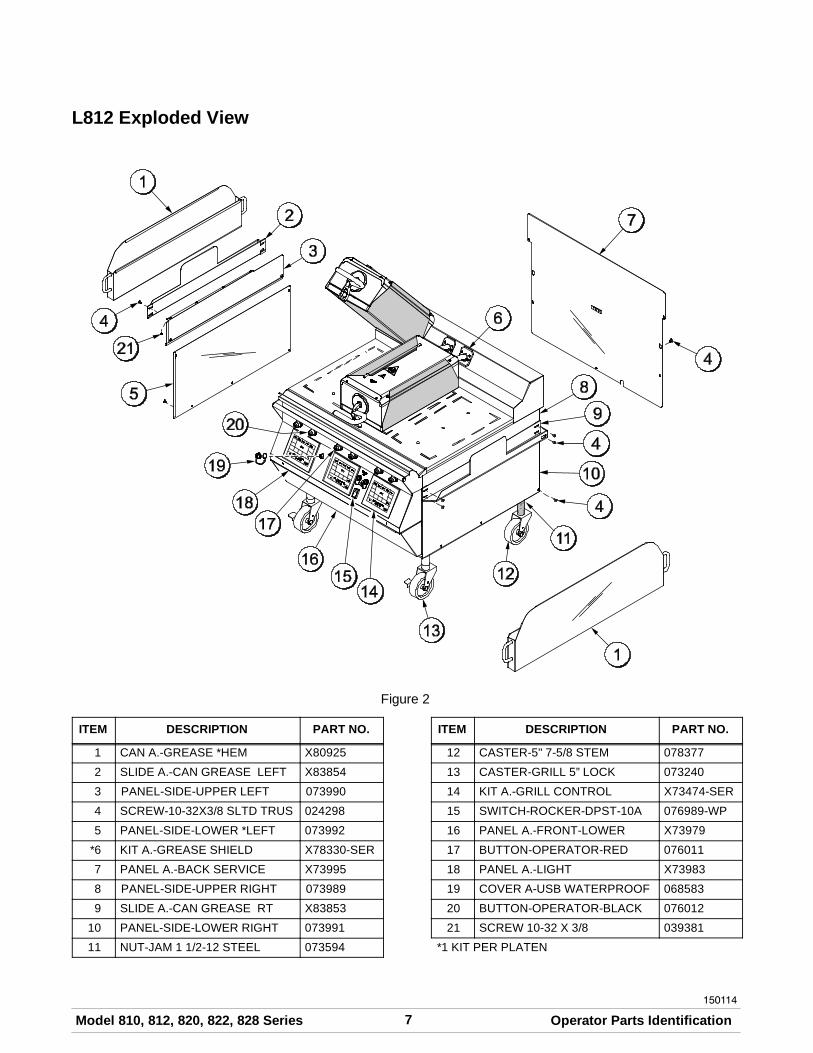
L812 Exploded View
Figure 2
ITEM DESCRIPTION PART NO.
1 CAN A.-GREASE *HEM X80925
2 SLIDE A.-CAN GREASE LEFT X83854
3 PANEL-SIDE-UPPER LEFT 073990
4 SCREW-10-32X3/8 SLTD TRUS 024298
5 PANEL-SIDE-LOWER *LEFT 073992
*6 KIT A.-GREASE SHIELD X78330-SER
7 PANEL A.-BACK SERVICE X73995
8 PANEL-SIDE-UPPER RIGHT 073989
9 SLIDE A.-CAN GREASE RT X83853
10 PANEL-SIDE-LOWER RIGHT 073991
11 NUT-JAM 1 1/2-12 STEEL 073594
ITEM DESCRIPTION PART NO.
12 CASTER-5" 7-5/8 STEM 078377
13 CASTER-GRILL 5” LOCK 073240
14 KIT A.-GRILL CONTROL X73474-SER
15 SWITCH-ROCKER-DPST-10A 076989-WP
16 PANEL A.-FRONT-LOWER X73979
17 BUTTON-OPERATOR-RED 076011
18 PANEL A.-LIGHT X73983
19 COVER A-USB WATERPROOF 068583
20 BUTTON-OPERATOR-BLACK 076012
21 SCREW 10-32 X 3/8 039381
*1 KIT PER PLATEN

8 Model 810, 812, 820, 822, 828 SeriesOperator Parts Identification
150114
L820 / G820 Exploded View
Figure 3
ITEM DESCRIPTION PART NO.
1 CAN A.-GREASE HEM X80925
2 SLIDE A.-CAN GREASE LEFT X83854
3 PANEL-SIDE UPPER LEFT 073990
4 SCREW-10-32X3/8 SLTD TRUS 024298
5 SCREW 10-32 X 3/8 039381
6 PANEL-BACK-LOWER LEFT 073992
*7 KIT A.-GREASE SHIELD X78330-SER
8 PANEL-BACK-LOWER 069656
9 PANEL-SIDE UPPER RIGHT 073989
10 SLIDE A.-CAN GREASE RIGHT X83853
11 PANEL-SIDE-LOWER-RIGHT 073991
ITEM DESCRIPTION PART NO.
12 NUT-JAM 1-1/2-12 STEEL 073594
13 CASTER-5" 7-5/8 STEM 078377
14 CASTER-GRILL 5" W/LOCK 073240
15 KIT A.-GRILL CONTROL X73474-SER
16 BUTTON-OPERATOR-RED 076011
17 SWITCH-ROCKER-DPST-10A 076989-WP
18 PANEL A.-FRONT-LOWER X69660
19 COVER A.-USB 068583
**20 GUARD-LENSE 075288
21 BUTTON-OPERATOR-BLACK 076012
**22 LABEL-CONTROL PANEL 075699SYM3
* 1 KIT PER PLATEN**INTERNATIONAL, ONLY

9Model 810, 812, 820, 822, 828 Series Operator Parts Identification
150114
L822 Exploded View
Figure 4
ITEM DESCRIPTION PART NO.
1 CAN A.-GREASE *HEM X80925
2 SLIDE A.-CAN GREASE LEFT X83854
3 PANEL-SIDE UPPER-LT 073990
4 SCREW-10-32X3/8 SLTD 024298
5 SCREW-10-32X3/8 UNSL HWH 039381
6 PANEL-SIDE-LOWER *LEFT 073992
7 KIT A.-GREASE SHIELD* X78330-SER
8 PANEL-BACK-SERVICE 069656
9 PANEL-SIDE UPPER-RT 073989
10 SLIDE A.-CAN GREASE RIGHT X83853
11 PANEL-SIDE-LOWER *RIGHT 073991
ITEM DESCRIPTION PART NO.
12 NUT-JAM 1 1/2-12 STEEL 073594
13 CASTER-5" 7-5/8 STEM RIGID 078377
14 CASTER-5" 7-5/8 SWIVELW/LOCK
073240
15 KIT A.-GRILL CONTROL-GENMRKT
X73474-SER
16 BUTTON-OPERATOR-RED 076011
17 SWITCH-ROCKER-DPST-10A 076989-WP
18 PANEL-FRONT-LOWER 069661
19 COVER A.-USB WATERPROOF 068583
20 BUTTON-OPERATOR-BLACK 076012

10 Model 810, 812, 820, 822, 828 SeriesOperator Parts Identification
150107
L828 / G828 Exploded View
Figure 5
ITEM DESCRIPTION PART NO.
1 CAN A.-GREASE *HEM X81942
2 PANEL-SIDE UPPER-LT 081973
3 SCREW-10-32X3/8 SLTD 024298
4 SCREW-10-32X5/8 UN SL 039382
5 PANEL-SIDE *LEFT 081981
6 KIT A.-GREASE SHIELD X78330-SER
7 PANEL-REAR 082021
8 PANEL-SIDE UPPER-R 081982
9 PANEL-GREASE CANRETAINER
082020
10 CASTER-5 IN. 7-5/8 STEM 081971
11 LOCK-WHEEL 076522
ITEM DESCRIPTION PART NO.
12 PANEL-SIDE *RIGHT 081980
13 CASTER-5" 7-5/8STEM-BRAKE
081974
14 KIT A.-GRILL CONTROL X73474-SER
15 PANEL A.-FRONT-LOWER X81951
**16 GUARD-LENSE 075288
**17 LABEL-CONTROL PANEL 075699SYM3
18 SWITCH-ROCKER-DPST-10A 076989-WP
19 COVER A.-USB 068583
20 BUTTON-OPERATOR-RED 076011
21 BUTTON-OPERATOR-BLACK 076012

11Model 810, 812, 820, 822, 828 Series Operator Parts Identification
150514
Accessories Supplied With Grill
Figure 6
ITEM DESCRIPTION PART NO.
1 SHEET-RELEASE - BOX OF 9 080595
2 RETAINER-SHEET RELEASE(RETENTION BAR) (QTY OF 3)
080594
3 CLIP-RELEASE MATERIALW/TAB (QTY OF 6)
072673
ITEM DESCRIPTION PART NO.
4 SCRAPER-TEFLON WIPER 075887
5 STRIP-REPLACEMENT 075888
*6 CLEANER-STERA SHEEN(1 QT. SAMPLE)
073160-SAM
*NOTE: A SAMPLE CONTAINER OF CLEANER ISSENT WITH THE UNIT. FOR REORDERS, ORDERPART NO. 073160 - QTY. OF (6) 1 QT. BOTTLES.

12 Model 810, 812, 820, 822, 828 SeriesOperator Parts Identification
150514
Optional Accessories Available From Local Taylor Distributor
Figure 7
ITEM DESCRIPTION PART NO.
1 SCRAPER-BLADE (6 PACK) 073891
2 SCRAPER-GRILL 073225
3 PAD-CLEANING (BOX OF 10) 073737
4 HOLDER-PAD-CLEANING 073736
ITEM DESCRIPTION PART NO.
5 BIN A.-TOOL STORAGE X73829
6 CLEANER-STERA SHEEN(CASE OF 6, 1 QT. BOTTLES)
073160

13Model 810, 812, 820, 822, 828 Series Important: To the Operator
150514
Section 5 Important: To the Operator
Note: The Model 810 three platen grill has been selected for illustration purposes.
Figure 8
ITEM DESCRIPTION
1 RAISE BUTTON
2 STANDBY/COOK MODE BUTTON
3 USB COVER/CONNECTION
4 POWER SWITCH
5 CLEAN MODE KEY
ITEM DESCRIPTION
6 PROGRAM KEY
*7 TEMPERATURE INDICATOR LIGHTS
8 POWER KEY
9 FUNCTION DISPLAY
10 MENU SELECT KEYS
*NOTE: T-F = TOP FRONT, T-R = TOP REAR,B-F = BOTTOM FRONT, B-M = BOTTOM MIDDLE,B-R = BOTTOM REAR

14 Model 810, 812, 820, 822, 828 SeriesOperating Procedures
130206
Section 6 Operating Procedures
The three platen Model L810 has been selected toillustrate the step-by-step procedures. For grillsequipped with less than three platens, perform thefollowing steps as appropriate for your grill platenconfiguration.
Daily Opening Procedures
Before operating the grill, the release sheets mustbe installed on the upper platens. The releasesheets should be reversed and rotated on a dailybasis (dark color side vs. light color side.)
Perform the following steps for installing releasesheets:
CAUTION: Make sure the grill is COOLbefore attempting to install or remove releasesheets.
Step 1Slide the release sheet retainer through the hemmedend of the release sheet.
Figure 9
Step 2Hook the release sheet retainer on the release sheetshoulder screws at the top of the upper platen.
Figure 10
Step 3Hold the non-hemmed end of the release sheet.Gently pull the sheet tight, wrapping it around theplaten in a side-to-side manner.
Figure 11
Note: Check the alignment of the release sheet andmake sure it fits smoothly over the upper platen.
15Model 810, 812, 820, 822, 828 Series Operating Procedures
130205
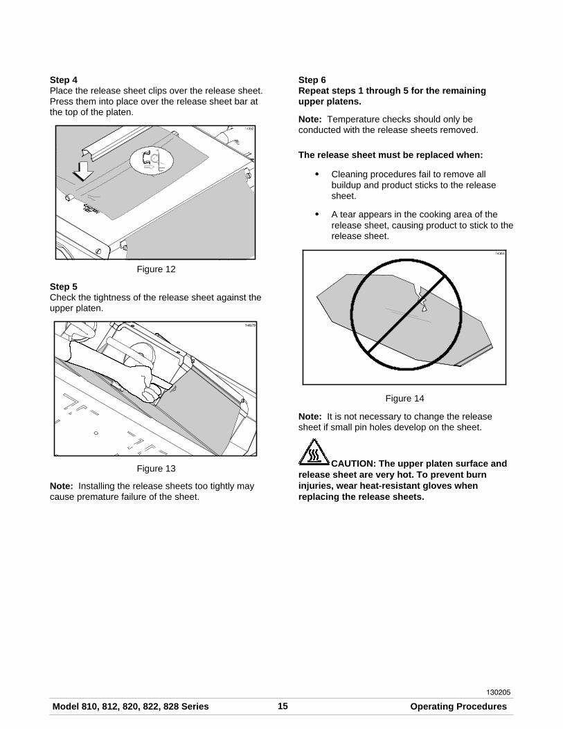
Step 4Place the release sheet clips over the release sheet.Press them into place over the release sheet bar atthe top of the platen.
Figure 12
Step 5Check the tightness of the release sheet against theupper platen.
Figure 13
Note: Installing the release sheets too tightly maycause premature failure of the sheet.
Step 6Repeat steps 1 through 5 for the remainingupper platens.
Note: Temperature checks should only beconducted with the release sheets removed.
The release sheet must be replaced when:
S Cleaning procedures fail to remove allbuildup and product sticks to the releasesheet.
S A tear appears in the cooking area of therelease sheet, causing product to stick to therelease sheet.
Figure 14
Note: It is not necessary to change the releasesheet if small pin holes develop on the sheet.
CAUTION: The upper platen surface andrelease sheet are very hot. To prevent burninjuries, wear heat-resistant gloves whenreplacing the release sheets.

16 Model 810, 812, 820, 822, 828 SeriesOperating Procedures
110602
Care of Release Sheets
DO NOT:
S DO NOT fold or crease.
Figure 15
S DO NOT touch with sharp objects, grillscrapers, or abrasive pads.
S DO NOT place under other equipment orobjects.
S DO NOT hot-hose or soak in water.
DO:
S DO clean with a squeegee after each run ofproduct.
S DO wipe with a clean, sanitizer-soaked grillcloth a minimum of 4 times per hour andmore often during peak periods.
S DO clean daily on both sides, using anapproved high temperature grill cleaner andthe grill cleaning pad and holder identifiedon page 12.
IMPORTANT! Clean the releasesheets using the grill cleaning pad andholder identified on page 12 ONLY. Usingany other pad and holder will damage therelease sheets.
Figure 16
Note: Contact your local Taylor Distributor topurchase the correct grill cleaning pad and holder.(See page 12.)
S DO rinse both sides of the release sheetwith a clean, sanitizer-soaked grill cloth toremove the cleaner. Allow the release sheetto dry on a clean, flat surface.
S DO rotate the release sheet daily andre-install on opposite side than previouslyused (dark color side vs. light color side).
Start Up of the Grill
IMPORTANT! The lower grill surface and theupper platen MUST BE CLEAN before startingthese procedures.
Step 1Place the power switch in the ON position.
Figure 17
17Model 810, 812, 820, 822, 828 Series Operating Procedures
150514
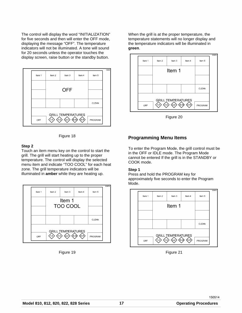
The control will display the word “INITIALIZATION”for five seconds and then will enter the OFF mode,displaying the message “OFF”. The temperatureindicators will not be illuminated. A tone will soundfor 20 seconds unless the operator touches thedisplay screen, raise button or the standby button.
Figure 18
Step 2Touch an item menu key on the control to start thegrill. The grill will start heating up to the propertemperature. The control will display the selectedmenu item and indicate “TOO COOL” for each heatzone. The grill temperature indicators will beilluminated in amber while they are heating up.
Figure 19
When the grill is at the proper temperature, thetemperature statements will no longer display andthe temperature indicators will be illuminated ingreen.
Figure 20
Programming Menu Items
To enter the Program Mode, the grill control must bein the OFF or IDLE mode. The Program Modecannot be entered If the grill is in the STANDBY orCOOK mode.
Step 1Press and hold the PROGRAM key forapproximately five seconds to enter the ProgramMode.
Figure 21

18 Model 810, 812, 820, 822, 828 SeriesOperating Procedures
150402
Step 2The PASSWORD screen will appear. Enter theOperator Password “STORE1” and press the OKkey.
Figure 22
Step 3The PROGRAM MODE screen will appear,displaying the version of the software, motor control,and motor control boot, along with several keys.
Figure 23
UNITS Key
The UNITS key is used to select either English ormetric units of measure. If English is selected, thetemperatures will be displayed in _F and gaps will bedisplayed in inches. If Metric is selected, thetemperatures will be displayed in _C and gaps willbe displayed in mm.
ADJUST VOLUME Key
The ADJUST VOLUME key displays the currentvolume. To increase or decrease the volume, usethe UP and DOWN arrow keys.
Note: To scroll at a faster rate, press and hold thearrow key.
Figure 24
MENU EDIT Key
The MENU EDIT key is used to program a newmenu item or make changes to an existing one.When the MENU EDIT key is pressed, the followingscreen will display.
Figure 25
If there is more than one screen of menu items,press the Previous or Next arrow keys to access theother menu items.

19Model 810, 812, 820, 822, 828 Series Operating Procedures
150406
Press the menu item key to be programmed. Thefollowing screen will display.
Figure 26
To edit a menu item, press the menu item key tobring up a virtual keyboard. Use the back arrow toscroll to the beginning of the name (Item 1). Pressthe “Del” key until all of the characters are removed.Type in the desired name (up to 9 characters) andpress the OK key to return to the previous screen.
If the box is blank (creating a new Item), type in thedesired name (up to 9 characters). A maximum oftwo lines of description can be used. Press the OKkey to return to the previous screen.
Figure 27
ACTIVE: YES or NO
Pressing the ACTIVE key toggles between “YES”and “NO.” Selecting “YES” will allow the menu itemto be displayed on the main menu screen. If “NO” isselected, the menu settings remain saved in thecontrol after the OK key is pressed, but will not bevisible on the main menu screen. (See Figure 26.)
DELETE Item
This key is used to delete the selected menu item.When pressed, the screen displays “YES” or “NO”.Selecting “YES” removes the item from the controlmemory.
TOP TEMP
This key displays the current set point temperaturefor the platen. To increase or decrease thetemperature, use the UP and DOWN arrow keys.
Note: To scroll at a faster rate, press and hold thearrow key.
BOTTOM TEMP
This key displays the current set point temperaturefor the lower grill surface. To increase or decreasethe temperature, use the UP and DOWN arrow keys.
Note: When setting the temperatures for a givenitem, the limits are 150°F to 450°F (66°C to 232°C)for the upper platen and 150°F to 400°F (66°C to204°C) for the lower grill surface.
CLAM/FLAT
This key displays the current setting (CLAM orFLAT) associated with that function. Pressing thekey toggles the mode to the opposite selection.
If a CLAM item is selected, the upper platen willlower to the specified gap to allow two-sidedcooking.
If a FLAT item is selected, the product is cooked onthe lower cook surface, only. The upper platensremain in the up position.
IMPORTANT: The upper platens remainat set temperature in the FLAT mode. Avoidcontact with the upper platens and grill surfaces toavoid burn injuries.
GAP: This key is only active if CLAM has beenselected. The key displays the platen gap (in inchesor mm) associated with the FUNCTION. To increaseor decrease the gap setting, press and hold the UPand DOWN arrow keys.
Note: The gap is designed to range from 0 to 1”(2.54 mm). Operating the grill to cook productsthicker than 1” (2.54 mm) will not allow proper platenoperation.

20 Model 810, 812, 820, 822, 828 SeriesOperating Procedures
150514
MULTIPLE TIMING FUNCTIONS: There are fourtiming functions for clam and flat menu items. Eachfunction has a set of parameters associated with it.The functions currently associated with the menuitem are displayed. Pressing function 1, function 2,or function 3 will bring up the next function in the list.The functions provided are:
S REMOVE IN
S SEAR IN
S TURN IN
S SEAR/TURN IN
MULTIPLE GAP FUNCTION - LINK: Any time asecond or third timing function is programmed into amenu item, the Link function is automaticallyactivated to “Yes.” The Link feature allows the platento move up to the Home position and then comeback down to the next predetermined gap and timingfunction.
Note: If the Link function is on “Yes,” the platen armstays down and only the platen will move up anddown. If the Link function is on “No,” the platen armwill rise to the up position and then the Standbybutton will have to be manually pressed to start asecond or third timing function.
Figure 28
In the example shown in Figure 28, the platen willcome down and SEAR the product for 30 seconds.After that time has expired, with the LINK functionset to “YES,” the platen will move up to the Homeposition and then come back down to the next setgap for another 30 seconds. Once that time hasexpired, with the LINK function set to “NO,” theplaten arm will raise all the way up so that theproduct can be turned.
After the product has been turned, the Standbybutton will need to be pressed to bring the platenback down. Once it reaches the next set gap, theproduct will then cook for another 60 seconds. Afterthat time has expired, the platen arm will raise all theway up and the product can be removed.
Note: Each function is an accumulative timingsequence in seconds.
SEAR IN - 30 secondsTURN IN - 30 secondsREMOVE IN - 60 secondsTotal cook time would be 120 seconds.
ALARM AUTO/MANUAL: This key displays thecurrent status of the alarm mode. Pressing the keytoggles the mode to the opposite selection.
If “ALARM AUTO” is selected, the alarm will soundat the end of the cook cycle automatically and thenstop after 5 seconds has elapsed.
Selecting ALARM MANUAL requires the operatortouch anywhere on the display screen or the raise orstandby buttons to stop the alarm.
XXX SECONDS: This key displays the timeassociated with that menu item in seconds. Toincrease or decrease the seconds setting, press andhold the UP and DOWN arrow keys.
GAP: Each timing function has an associated gapsetting. This setting can be changed selecting thegap value. Press and hold the UP and DOWN arrowkeys to increase and decrease the gap value.
Upon completion of all programming selections,save the selections by pressing the OK key. Toreturn to the main display screen without saving theprogramming selections, press the EXIT key.

21Model 810, 812, 820, 822, 828 Series Operating Procedures
110603
SERVICE CONTACT INFORMATION Key
Press the SERVICE CONTACT INFORMATION keyto view the programmed service contact information.
Figure 29
LANGUAGE Key
The Language key is used to select the languagethe control will display. The available languages areEnglish, French, Portuguese, Russian, and Spanish.See Figure 32.
STANDBY ALERT - YES Key
Pressing this key toggles between YES and NO. If“Yes” is selected, an alert will sound when the platenhas not been used for a Cook Cycle or placed intothe Standby mode for a predetermined amount oftime. See Standby Alert Timer. If “No” is selected,the platen can still be placed into the Standbyposition, but there will be no set timing functionassociated with it.
Note: This function should be used to helpconserve the energy cost of running the grillduring slow times.
VIEW HELP Key
The View Help key is not functional at this time(future development).
STANDBY ALERT TIME Key
This is a programmable timer that can be set from5:00 - 60:00 minutes. After the selected time hasexpired, an alert will sound and the screen willdisplay “PUT INTO STANDBY.” Once the StandbyAlert has sounded, it will take three Standby buttonpresses to bring the platen down into the Standbyposition. The first button press will clear the alert andthe next two presses will actually bring the platendown into the Standby position. Button pressesshould be done at approximately one secondintervals.
Note: If the button presses are done too quickly,the platen will come down and initiate a cookcycle instead of placing the platen into Standby.Pressing the Raise button will cancel the cookcycle.
Loading Store Menu Items To USB
The same USB flash drive that was used to loadsoftware into the grill can be used to perform thisprocedure.
Step 1Remove the USB cap from the USB connector toaccess the USB port.
Step 2Insert the USB flash drive into the USB port.
Step 3Press and hold the PROGRAM key for 5 seconds toenter the Program Mode.
Figure 30

22 Model 810, 812, 820, 822, 828 SeriesOperating Procedures
150514
Step 4Enter the Operator Password “STORE1” and pressthe OK key.
Figure 31
Step 5Press the MENU EDIT key.
Figure 32
Step 6Press the STORE MENU TO USB key.
Figure 33
Step 7Using the keyboard displayed on the control, enter afile name to save the menu item. The name canhave up to 8 characters and must have no spaces inthe name. Pressing the OK key will save the menuitem to the USB flash drive. Press the EXIT keythree times to return to the menu item screen.
Step 8Remove the USB flash drive from the USB port andreinstall the USB cable cap on the USB connector.
Loading Menu Items From USB
Once the menu file is loaded on the USB flash drive,the next control board can be programmed from theUSB flash drive.
Step 1Repeat Steps 1 through 5 from “Loading Store MenuItems to USB.”
Step 2Press the LOAD MENU FROM USB key.
Step 3The control can display up to 40 different menuoptions loaded on the USB flash drive. Select thekey for the correct menu to load. The control willdisplay “DONE” at the bottom of the screen whenthe menu is loaded. Press the EXIT key twice toreturn to the menu item screen.
Step 4Remove the USB flash drive from the USB port andreinstall the USB cable cap on the USB connector.
Step 5To load menu items from the USB flash drive toanother control board, repeat these software loadingprocedures.

23Model 810, 812, 820, 822, 828 Series Operating Procedures
130312
Patty Placement & Removal
Placement procedures of meat products must befollowed on the grill. The meat must be placed onthe lower grill surface from front to back. When thecook cycle is complete, the upper platen will raise.
Note: It is very important that all patties beremoved from the lower grill surface in the samesequence that they were placed before cooking.
Patties must be removed immediately after theupper platen has been raised to the OPEN positionand after the meat has been seasoned.
Patties are generally placed two at a time from frontto back of grill and right to left. The removal order ofthe patties is shown in the diagrams by the numbershown in the center of each patty.
Figure 34

24 Model 810, 812, 820, 822, 828 SeriesOperating Procedures
150514
Operating Procedures
Cooking Product
Step 1Select the menu item to be cooked. When the grill isat the correct temperature, the grill temperatureindicators will be green and the control will notdisplay any temperature statements.
Step 2Quickly place the product on the lower grill surfacefrom front to back, per the Patty Placement Guide onpage 23. Make sure all product is inside the etchedtarget zone.
Step 3Press the STANDBY button once.
Figure 35
The display reads “MOVING DOWN” as the platenlowers to the cook surface.
During the cooking cycle, the display will show thename of the current menu item, “REMOVE IN”, andthe time remaining until the product should beremoved.
Figure 36
At the end of the cook cycle, the control will display“DONE”, a tone will sound, and the platen willautomatically raise.
Figure 37
Note: To cancel a cook cycle at any time, press theRAISE button. A tone will sound and the display willread “CANCEL” for five seconds and then enter theIDLE mode.

25Model 810, 812, 820, 822, 828 Series Operating Procedures
150514
Flat Item Cook Cycle Screen
The following is an example of a flat item cook cyclescreen. The first line function default is REMOVE IN.
Figure 38
To edit a menu item, press the menu item key tobring up a virtual keyboard. Press the BACK keyuntil all of the characters are removed. Type in thedesired name (up to 9 characters) and press the OKkey to return to the previous screen.
If the box is blank (creating a new Item), type in thedesired name (up to 9 characters). A maximum oftwo lines of description can be used. Press the OKkey to return to the previous screen.
Figure 39
Flat Menu Item Timing Function
Up to four flat menu items can be cooked in onezone at any time. Select any flat item from the menuscreen and press the Standby button once to initiatethe countdown timer. The “remove in” time willdisplay on the screen. Select the same or anotherflat menu item and press the Standby button againto initiate the second countdown timer. The displayscreen will then change, showing the “remove in”time for both of the flat menu items selected. Followthis same procedure for up to four flat menu items tobe displayed.
Figure 40
To Cancel a Flat Menu Item Timing Function
If only one flat menu item timing function isdisplayed, press the Raise button. If two or more flatmenu item timing functions are displayed, pressand hold your finger on the menu item to becancelled and press the Raise button at the sametime.
Figure 41
26 Model 810, 812, 820, 822, 828 SeriesOperating Procedures
150529
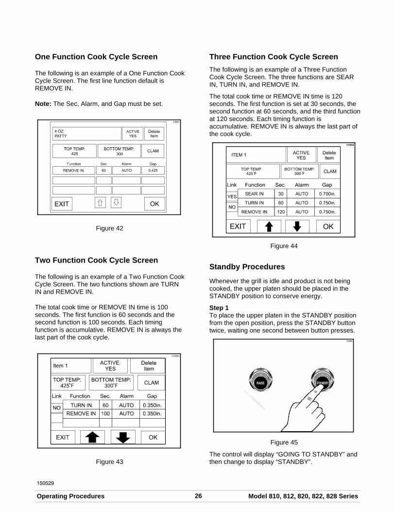
One Function Cook Cycle Screen
The following is an example of a One Function CookCycle Screen. The first line function default isREMOVE IN.
Note: The Sec, Alarm, and Gap must be set.
Figure 42
Two Function Cook Cycle Screen
The following is an example of a Two Function CookCycle Screen. The two functions shown are TURNIN and REMOVE IN.
The total cook time or REMOVE IN time is 100seconds. The first function is 60 seconds and thesecond function is 100 seconds. Each timingfunction is accumulative. REMOVE IN is always thelast part of the cook cycle.
Figure 43
Three Function Cook Cycle Screen
The following is an example of a Three FunctionCook Cycle Screen. The three functions are SEARIN, TURN IN, and REMOVE IN.
The total cook time or REMOVE IN time is 120seconds. The first function is set at 30 seconds, thesecond function at 60 seconds, and the third functionat 120 seconds. Each timing function isaccumulative. REMOVE IN is always the last part ofthe cook cycle.
Figure 44
Standby Procedures
Whenever the grill is idle and product is not beingcooked, the upper platen should be placed in theSTANDBY position to conserve energy.
Step 1To place the upper platen in the STANDBY positionfrom the open position, press the STANDBY buttontwice, waiting one second between button presses.
Figure 45
The control will display “GOING TO STANDBY” andthen change to display “STANDBY”.

27Model 810, 812, 820, 822, 828 Series Operating Procedures
150529
Note: If the Standby Alert mode is active and thealarm is sounding, the STANDBY button must bepressed 3 times, with a one second pausebetween presses. The first press cancels the alarmand the second two presses lower the upper plateninto the Standby position.
Step 2To raise the upper platen to the OPEN position toresume cooking, press the RAISE button.
Figure 46
CAUTION: Never use force to raise theupper platen. Damage to components may result.Only use the RAISE button to open the upper platen.
Menu Parameters
To view the settings and actual temperatures for thecurrent item, press and hold the menu item key aminimum of 5 seconds. The screen will display thecook time, gap setting, temperature set points andactual temperature readings for each zone for thatmenu item.
Figure 47
If a key is not pressed for 20 seconds, the grillcontrol will return to the normal display. Pushing theEXIT key will bring the display back to the maindisplay page.
To View Software Versions
Press and release the Program key after twoseconds to view the software versions and menuitem loaded onto the control. The following items willbe displayed:
Version: Current software version in thedisplay control
Menu: Current menu that is loaded intothe control
Motor ControlVersion:
Current software version in themotor control board
Motor ControlBoot Version:
Current bootloader softwareversion in the motor control board
Figure 48

28 Model 810, 812, 820, 822, 828 SeriesOperating Procedures
Cleaning After Each Run of Product
Step 1Using the grill scraper, scrape the grease on thelower grill surface from front to back. Do not scrapeacross the rear of the lower grill surface with the grillscraper.
Figure 49
Step 2Use the wiper squeegee to clean the release sheeton the upper platen. Hold the handle at a slightupward angle. Use a downward motion to clean thesheet. (Note: Do not use excessive pressure whenwiping the release sheet with the squeegee, as thiscan scratch or tear the release sheet.)
Figure 50
Step 3Using the wiper squeegee, push the grease at therear of the lower grill surface into the grease can. Donot use the grill scraper for this step.
Step 4Use the grill cloth to clean the back splash plate andthe bullnose areas as needed during operation.
Note: To increase the life of the release sheet, wipeit with a clean, sanitizer-soaked, folded grill cloth aminimum of four times every hour.
CAUTION: The upper platen surface isvery HOT! To prevent burn injuries, use extremecaution when wiping the release sheet.
Daily Cleaning Procedures
Note: The three platen Model L810 has beenselected to illustrate the step-by-step procedures.For grills equipped with less than three platens,perform the following steps as appropriate for yourgrill platen configuration.
Step 1Raise the upper platen to the OPEN position bypressing the red RAISE button.
Figure 51
29Model 810, 812, 820, 822, 828 Series Operating Procedures
150514
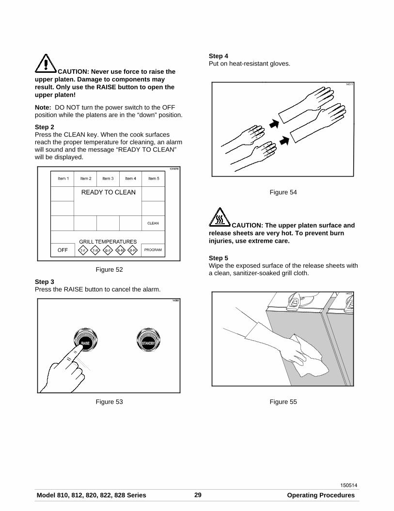
CAUTION: Never use force to raise theupper platen. Damage to components mayresult. Only use the RAISE button to open theupper platen!
Note: DO NOT turn the power switch to the OFFposition while the platens are in the “down” position.
Step 2Press the CLEAN key. When the cook surfacesreach the proper temperature for cleaning, an alarmwill sound and the message “READY TO CLEAN”will be displayed.
Figure 52
Step 3Press the RAISE button to cancel the alarm.
Figure 53
Step 4Put on heat-resistant gloves.
Figure 54
CAUTION: The upper platen surface andrelease sheets are very hot. To prevent burninjuries, use extreme care.
Step 5Wipe the exposed surface of the release sheets witha clean, sanitizer-soaked grill cloth.
Figure 55
30 Model 810, 812, 820, 822, 828 SeriesOperating Procedures
150304
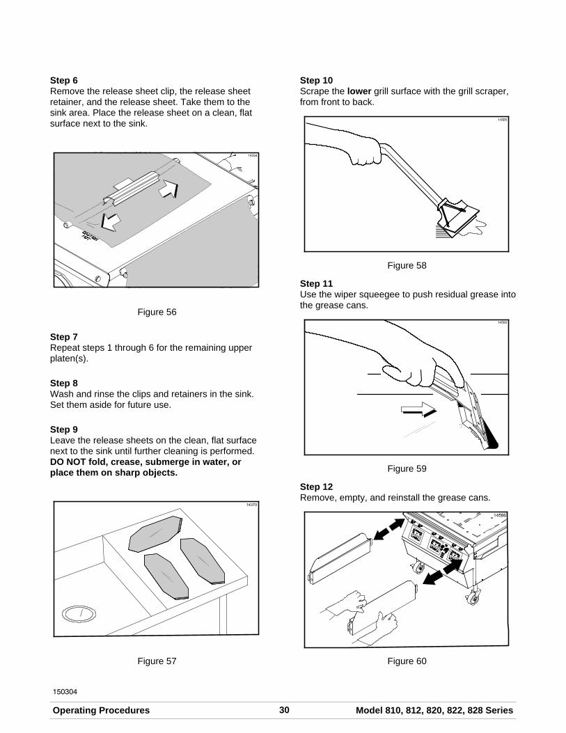
Step 6Remove the release sheet clip, the release sheetretainer, and the release sheet. Take them to thesink area. Place the release sheet on a clean, flatsurface next to the sink.
Figure 56
Step 7Repeat steps 1 through 6 for the remaining upperplaten(s).
Step 8Wash and rinse the clips and retainers in the sink.Set them aside for future use.
Step 9Leave the release sheets on the clean, flat surfacenext to the sink until further cleaning is performed.DO NOT fold, crease, submerge in water, orplace them on sharp objects.
Figure 57
Step 10Scrape the lower grill surface with the grill scraper,from front to back.
Figure 58
Step 11Use the wiper squeegee to push residual grease intothe grease cans.
Figure 59
Step 12Remove, empty, and reinstall the grease cans.
Figure 60

31Model 810, 812, 820, 822, 828 Series Operating Procedures
130201
Step 13Using an approved high temperature grill cleaner,pour approximately 3 oz. (90 ml) onto each 12”(305 mm) cook zone.
Figure 61
Step 14Firmly attach the non-abrasive pad to the grillcleaning pad holder.
IMPORTANT! Use the grill cleaning padand holder identified on page 12 ONLY. Usingany other pad and holder will damage the releasesheets.
Step 15Dip the pad into the grill cleaner.
IMPORTANT: DO NOT SCRUB while applyinggrill cleaner in the following steps:
Step 16Apply grill cleaner to the front side of the upperplatens.
Figure 62
Step 17Apply grill cleaner to the bottom of the platenhandles.
Figure 63
DO NOT use metal scrapers, abrasivepads, screens, or wire brushes. Damage tocomponents may result.
Step 18Apply grill cleaner to the platen surfaces.
Figure 64

32 Model 810, 812, 820, 822, 828 SeriesOperating Procedures
110610
Step 19Apply grill cleaner to the back side of the upperplatens.
Figure 65
Step 20Apply grill cleaner to the outer edges of the right andleft platens.
Step 21Press the STANDBY button twice to lower one of theplatens.
810 Only: Press the STANDBY button twice to lowerthe center platen. Apply grill cleaner to both sides ofthe center platen.
Step 22Apply grill cleaner to the inner edges of the right andleft platens.
Step 23Press the RAISE button to raise the lowered platen.
Step 24Lightly scrub the front side of the platens and thebottom of the platen handles with the non-abrasivepad until all soil has been liquified by the grillcleaner. For stubborn soils, apply additional grillcleaner and lightly scrub. Do not rinse the platensat this time.
Step 25Lightly scrub the platen cook surfaces.
Figure 66
Step 26Lightly scrub the back side of the upper platens.
Figure 67
Step 27Lightly scrub the outer edges of the right and leftplatens.
Step 28Press the STANDBY button twice to lower one of theplatens.
810 Only: Press the STANDBY button twice to lowerthe center platen. Lightly scrub both sides of thecenter platen.
Step 29Lightly scrub the inner edges of the right and leftplatens.
Step 30Press the RAISE button to raise the lowered platen.
Step 31With a clean, sanitizer-soaked grill cloth, rinse thefront, sides, and back of the platen surfaces.

33Model 810, 812, 820, 822, 828 Series Operating Procedures
130201
Step 32With a clean, sanitizer-soaked grill cloth, rinse thebottom of the platen handles, and the front, sides,and back of the platen surfaces.
Figure 68
Step 33With a clean, sanitizer-soaked grill cloth, rinse theplaten cook surfaces.
Figure 69
Step 34Press the STANDBY button twice to lower one of theplatens.
810 Only: Press the STANDBY button twice to lowerthe center platen. With a clean, sanitizer-soaked grillcloth, rinse both sides of the center platen.
Step 35With a clean, sanitizer-soaked grill cloth, rinse theinner edges of the right and left platens.
Step 36Press the RAISE button to raise the lowered platen.
Step 37With a clean, sanitizer-soaked grill cloth, wipe theexterior of all the platens, especially behind the rearof the upper platens (next to the arm assembly).
Step 38Starting at the back of the lower grill, spread theremaining grill cleaner over the entire surface. Donot scrub while applying product.
Step 39Lightly scrub the surface with the non-abrasive paduntil all soil has been liquified by the grill cleaner.
Figure 70
Note: The rear of the upper platen, as well as thetubular arm, can easily be wiped from the front of theunit. If cleaning is performed on a daily basis, thereshould be no carbon build-up.

34 Model 810, 812, 820, 822, 828 SeriesOperating Procedures
IMPORTANT!
DO NOT use a jet of water to clean or rinsethe grill.
DO NOT use cold water or ice to cool theupper platen or the lower cook surface.
Failure to follow these instructions may result in:
S serious electrical shock
S burns from hot steam
S liquid collecting inside the grill anddestroying electrical components
S damaged cook surfaces
Step 40Use the squeegee to remove the cleaner from thegrill surface.
Figure 71
To avoid damaging the grill:
S Never use grill screens on the upper platenor the lower grill surface.
S Never use any abrasives or cleaners otherthan the approved cleaner.
S Never allow the grill scraper or the abrasivecleaning materials to come in contact withthe release sheet.
Step 41Pour a small amount of lukewarm water on a clean,sanitizer-soaked grill cloth, while holding it over thelower grill surface. Wipe the lower grill surface untilall residue is removed.
Figure 72
IMPORTANT! Step 42 must be performedusing the grill cleaning pad and holder identifiedon page 12 ONLY. Using any other pad and holderwill damage the release sheet.
Note: Contact your local Taylor Distributor topurchase the correct grill cleaning pad and holder.(See page 12.)

35Model 810, 812, 820, 822, 828 Series Operating Procedures
150304
Step 42Place the release sheets flat on the lower grillsurface. Gently clean both sides of the sheets withan approved high temperature grill cleaner and thegrill cleaning pad and holder.
Figure 73
Step 43Rinse both sides of the release sheets with a clean,sanitizer-soaked grill cloth.
Figure 74
Step 44Place the release sheets on a clean, flat surface toair dry overnight.
Step 45Wipe the lower grill surface with a clean,sanitizer-soaked grill cloth. Repeat until no visiblesoil remains.
Step 46Remove and empty the grease cans.
Figure 75
Step 47Wash, rinse, and reinstall the grease cans.
Step 48Wipe all areas with a clean, sanitizer-soaked grillcloth.
Step 49Wipe all exterior panels.
24 Hour Stores Only:
Re-install the release sheets on the opposite sidethan previously used. Secure the sheets with therelease sheet clips and retainers. Start up the grillper instructions starting on page 14.
Figure 76

36 Model 810, 812, 820, 822, 828 SeriesOperating Procedures
120830
Non-24 Hour Stores Only:
Step 50Apply a light coat of vegetable oil to the entire lowergrill surface.
Figure 77
Step 51Leave the upper platens in the OPEN positionovernight.
Step 52Place the power switch in the OFF position.
Figure 78
37Model 810, 812, 820, 822, 828 Series Troubleshooting Guide
150514
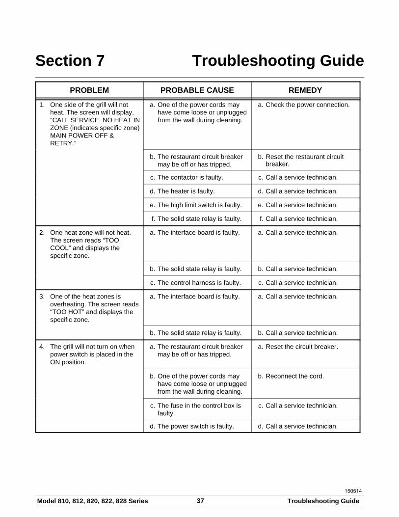
Section 7 Troubleshooting Guide
PROBLEM PROBABLE CAUSE REMEDY
1. One side of the grill will notheat. The screen will display,“CALL SERVICE. NO HEAT INZONE (indicates specific zone)MAIN POWER OFF &RETRY.”
a. One of the power cords mayhave come loose or unpluggedfrom the wall during cleaning.
a. Check the power connection.
b. The restaurant circuit breakermay be off or has tripped.
b. Reset the restaurant circuitbreaker.
c. The contactor is faulty. c. Call a service technician.
d. The heater is faulty. d. Call a service technician.
e. The high limit switch is faulty. e. Call a service technician.
f. The solid state relay is faulty. f. Call a service technician.
2. One heat zone will not heat.The screen reads “TOOCOOL” and displays thespecific zone.
a. The interface board is faulty. a. Call a service technician.
b. The solid state relay is faulty. b. Call a service technician.
c. The control harness is faulty. c. Call a service technician.
3. One of the heat zones isoverheating. The screen reads“TOO HOT” and displays thespecific zone.
a. The interface board is faulty. a. Call a service technician.
b. The solid state relay is faulty. b. Call a service technician.
4. The grill will not turn on whenpower switch is placed in theON position.
a. The restaurant circuit breakermay be off or has tripped.
a. Reset the circuit breaker.
b. One of the power cords mayhave come loose or unpluggedfrom the wall during cleaning.
b. Reconnect the cord.
c. The fuse in the control box isfaulty.
c. Call a service technician.
d. The power switch is faulty. d. Call a service technician.

38 Model 810, 812, 820, 822, 828 SeriesTroubleshooting Guide
150514
PROBLEM PROBABLE CAUSE REMEDY
5. The upper platen will not stayin the STANDBY mode, but willstay in the COOK position.
a. Incorrect use of the Standbybutton. The Standby buttonmay have been pressed twicetoo quickly.
a. Press the Standby buttontwice, one second apart, tolower the platen into theStandby position.
b. Faulty wire connections. b. Call a service technician.
6. The upper platen will not stayin the COOK or STANDBYposition.
a. Temperature is insufficient tosatisfy the indicator LED's.
a. Wait until the LED indicatorsturn green. This can happenduring the first 20 minutes afterthe grill has been turned on orafter a water cleaning.
b. The control harness is faulty. b. Call a service technician.
c. The interface board is faulty. c. Call a service technician.
d. The latch switch is faulty. d. Call a service technician.
e. The latch solenoid is faulty. e. Call a service technician.
f. The processor control is faulty. f. Call a service technician.
g. The pneumatic system isfaulty.
g. Call a service technician.
7. The upper platen will not stayin the COOK position, but willstay in the STANDBY mode.
a. The product is out ofspecification.
a. Product must be withinspecification (proper thickness,shape, etc.).
b. The processor control is not setproperly.
b. Call a service technician.
8. The upper platen opens toorapidly.
a. The orifice/check valve isincorrect or missing.
a. Call a service technician.
9. The screen displays “PLATENNOT LATCHED. CALLSERVICE-LATCH. IS ANOBJECT STUCK UNDER THEPLATEN? IF NO, COOK FLATITEMS ONLY.”
a. An item may be under platen,preventing it from latching.
a. Remove the item and try again.
b. The pneumatic system isfaulty.
b. Call a service technician.
c. The latch switch is faulty. c. Call a service technician.
d. The latch solenoid is faulty. d. Call a service technician.

39Model 810, 812, 820, 822, 828 Series Troubleshooting Guide
150514
PROBLEM PROBABLE CAUSE REMEDY
10. The display reads “UPPERPLATEN STUCK. CALLSERVICE-LATCH. IF THEPLATEN IS OPEN, COOKFLAT ITEMS ONLY.”
a. The arm bearings are dirty. a. Call a service technician.
b. The air cylinder is faulty. b. Call a service technician.
c. Plugged air lines to cylinders. c. Call a service technician.
11. The platen will not lower topreset gap height.
a. Excessive carbon build-up onthe shields.
a. Follow closing procedures toproperly clean and removecarbon build-up from theshields.
b. Defective motor interfaceboard.
b. Call a service technician.
c. Loose harness connections. c. Call a service technician.
d. Defective main displaycontroller.
d. Call a service technician.
e. Defective motors and cables. e. Call a service technician.
12. The product is under-cookedor overcooked.
a. The release sheet is worn. a. Replace the release sheet.
b. Incorrect cooking time. b. Reset the processor control forthe correct time.
c. Incorrect temperature setting. c. Adjust the processor control tothe proper setting.
d. The upper platen or lower grillsurface is not clean and/or hascarbon build-up.
d. Follow closing procedures toproperly clean the upper platenand the lower grill surface andto remove carbon build-up.
e. There is a grease or carbonbuild-up on the bottom of theupper platen handles.
e. Follow closing procedures toproperly clean and removecarbon build-up from thebottom of the platen handles.
f. Product is out of specification. f. Product must be withinspecified tolerances (thickness,shape, raw or frozentemperatures).
g. Product may haveaccumulated ice crystals.
g. Ensure that open boxes arekept closed and that all theproduct is covered duringstorage.

40 Model 810, 812, 820, 822, 828 SeriesTroubleshooting Guide
150514
PROBLEM PROBABLE CAUSE REMEDY
12. The product is under-cookedor overcooked. (Cont'd.)
h. Cooking procedures may havebeen followed incorrectly.
h. Ensure that the product wasremoved immediately after thecook cycle ended. Doublecheck that the correct productwas selected from the mainmenu screen.
i. Other equipment may be atfault.
i. Check temperatures of all meatstorage freezers. Make surethey are set to 0_F (-18_C).Check temperatures of all meatstorage refrigerators. Makesure they are set to 38-42_F(3-5_C).
j. The preset gap height isincorrect.
j. Validate the product settings(time, temperature, gap, etc.)are programmed in thecontroller correctly. Alwaysconsult with the owner andRegional Manager beforechanging the control settings.See guide for programminginstructions.
k. The heating zone is notheating.
k. Call a service technician.
13. The display reads “PROBEOPEN” and displays thespecific zone.
a. The thermocouple or thethermocouple interface boardis faulty.
a. Call a service technician.
14. The product is not cookingevenly.
a. The upper platen or lower grillsurface is not clean and/or hascarbon build-up.
a. Follow closing procedures toproperly clean the upper platenand the lower grill surface andto remove carbon build-up.
b. There is a grease or carbonbuild-up on the bottom of theupper platen handles.
b. Follow closing procedures toproperly clean and removecarbon build-up from thebottom of the platen handles.
c. The release sheet is worn. c. Replace release sheet.
d. Release sheet may be tooloose, causing poor heattransfer into product.
d. Readjust the sheet to ensure asnug fit. It should be tightenough to prevent creasing,sliding, or catching by thesqueegee. See guide forproper release sheetinstallation.

41Model 810, 812, 820, 822, 828 Series Troubleshooting Guide
150514
PROBLEM PROBABLE CAUSE REMEDY
14. The product is not cookingevenly. (Cont'd.)
e. The product is out ofspecification.
e. Product must be withinspecification (proper thickness,shape, etc.).
f. The platen is not level. f. Call a service technician.
g. The preset gap height isincorrect.
g. Call a service technician.
h. Air pressure is not highenough.
h. Call a service technician.
15. The display reads “HOMESWITCH STUCK ON. CLAMITEMS BLOCKED. CALL FORSERVICE.”
a. Two sided cooking options areblocked.
a. Turn the control off and thenback on to clear the fault.
b. Defective stepper motor. b. Call a service technician.
c. Defective stepper motor wireharness.
c. Call a service technician.
d. Defective home switch. d. Call a service technician.
e. Defective motor control. e. Call a service technician.
16. The display reads “HOMESWITCH NOT SEEN. CLAMITEMS BLOCKED. CALL FORSERVICE.”
a. Defective motor control. a. Call a service technician.
b. Defective stepper motor. b. Call a service technician.
c. Defective stepper motor wireharness.
c. Call a service technician.
d. Defective home switch. d. Call a service technician.
e. Broken platen cable. e. Call a service technician.

42 Model 810, 812, 820, 822, 828 SeriesLimited Warranty on Equipment
131205
Section 8 Limited Warranty on Equipment
TAYLOR COMPANY LIMITED WARRANTY ON CROWN SERIES GRILLS
Taylor Company, a division of Carrier Commercial Refrigeration, Inc. (“Taylor”) is pleased to provide this limitedwarranty on new Taylor-branded Crown Series grill equipment available from Taylor to the market generally (the“Product”) to the original purchaser only.
LIMITED WARRANTY
Taylor warrants the Product against failure due to defect in materials or workmanship under normal use andservice as follows. All warranty periods begin on the date of original Product installation. If a part fails due todefect during the applicable warranty period, Taylor, through an authorized Taylor distributor or service agency,will provide a new or re-manufactured part, at Taylor’s option, to replace the failed defective part at no charge forthe part. Except as otherwise stated herein, these are Taylor’s exclusive obligations under this limited warranty fora Product failure. This limited warranty is subject to all provisions, conditions, limitations and exclusions listedbelow and on the reverse (if any) of this document.
Product Part Limited Warranty Period
Taylor Crown Series Grills Air compressor (excluding tank, solenoid, pressureswitch, check valve, air cylinder, fittings, and airline)
Two (2) years
The upper platen’s aluminum casting and shroudonly, and excluding all other upper platencomponents, including those internal to the upperplaten
Two (2) years
Microprocessor control Three (3) years
Parts not otherwise listed in this table or excludedbelow
One (1) year
LIMITED WARRANTY CONDITIONS
1. If the date of original installation of the Product cannot be verified, then the limited warranty period beginsninety (90) days from the date of Product manufacture (as indicated by the Product serial number). Proof ofpurchase may be required at time of service.
2. This limited warranty is valid only if the Product is installed and all required service work on the Product isperformed by an authorized Taylor distributor or service agency, and only if genuine, new Taylor parts areused.
3. Installation, use, care, and maintenance must be normal and in accordance with all instructions contained inthe Taylor Operator’s Manual.
4. Defective parts must be returned to the authorized Taylor distributor or service agency for credit.
LIMITED WARRANTY EXCEPTIONS
This limited warranty does not cover:
1. Labor or other costs incurred for diagnosing, repairing, removing, installing, shipping, servicing or handling ofdefective parts, replacement parts, or new Products.
2. Normal maintenance and cleaning as outlined in the Taylor Operator’s Manual, including cleaning of carbonand grease buildup.
3. Required service, whether cleaning or general repairs, to return the Product’s cooking surface assemblies,including the upper platen and lower plate, to an operational condition to achieve proper cooking or allowproper assembly of release sheets and clips as a result of grease build-up on the cooking surfaces, includingbut not limited to the platen and plate, sides of the shroud or top of the shroud.

43Model 810, 812, 820, 822, 828 Series Limited Warranty on Equipment
141020
4. Replacement of the Product’s cooking surfaces, including the upper platen and lower plate, due to pitting orcorrosion (or in the case of the upper platen, due to loss of plating) as a result of damage due to the impactof spatulas or other small wares used during the cooking process or as a result of the use of cleaners,cleaning materials or cleaning processes not approved for use by Taylor.
5. Replacement of wear items designated as Class “000” parts in the Taylor Operator’s Manual, as well as anyrelease sheets and clips.
6. External hoses, electrical power supplies, and machine grounding.
7. Parts not supplied or designated by Taylor, or damages resulting from their use.
8. Return trips or waiting time required because a service technician is prevented from beginning warrantyservice work promptly upon arrival.
9. Costs incurred to address food safety issues when the technician determines food safety standards are metand the Product gaps and grill temperatures are within specification.
10. Failure, damage or repairs due to faulty installation, misapplication, abuse, no or improper servicing,unauthorized alteration or improper operation or use as indicated in the Taylor Operator’s Manual, includingbut not limited to the failure to use proper assembly and cleaning techniques, tools, or approved cleaningsupplies .
11. Failure, damage or repairs due to theft, vandalism, wind, rain, flood, high water, water, lightning, earthquakeor any other natural disaster, fire, corrosive environments, insect or rodent infestation, or other casualty,accident or condition beyond the reasonable control of Taylor; operation above or below the electrical or gasspecification of the Product; or components repaired or altered in any way so as, in the judgment of theManufacturer, to adversely affect performance, or normal wear or deterioration.
12. Any Product purchased over the Internet.
13. Failure to start due to voltage conditions, blown fuses, open circuit breakers, or damages due to theinadequacy or interruption of electrical or gas service.
14. Electricity, gas or other fuel costs, or increases in electricity, gas or other fuel costs from any reasonwhatsoever.
15. ANY SPECIAL, INDIRECT OR CONSEQUENTIAL PROPERTY OR COMMERCIAL DAMAGE OF ANYNATURE WHATSOEVER. Some jurisdictions do not allow the exclusion of incidental or consequentialdamages, so this limitation may not apply to you.
This limited warranty gives you specific legal rights, and you may also have other rights which vary fromjurisdiction to jurisdiction.

44 Model 810, 812, 820, 822, 828 SeriesLimited Warranty on Equipment
LIMITATION OF WARRANTY
THIS LIMITED WARRANTY IS EXCLUSIVE AND IS IN LIEU OF ALL OTHER WARRANTIES, CONDITIONSAND/OR REMEDIES UNDER THE LAW, INCLUDING ANY IMPLIED WARRANTIES OR CONDITIONS OFMERCHANTABILITY OR FITNESS FOR A PARTICULAR PURPOSE. THE ORIGINAL OWNER'S SOLEREMEDY WITH RESPECT TO ANY PRODUCTS SHALL BE REPAIR OR REPLACEMENT OF DEFECTIVECOMPONENTS UNDER THE TERMS OF THIS LIMITED WARRANTY. ALL RIGHTS TO CONSEQUENTIALOR INCIDENTAL DAMAGES (INCLUDING CLAIMS FOR LOST SALES, LOST PROFITS, PRODUCT LOSS,PROPERTY DAMAGES OR SERVICE EXPENSES) ARE EXPRESSLY EXCLUDED. THE EXPRESSWARRANTIES MADE IN THIS LIMITED WARRANTY MAY NOT BE ALTERED, ENLARGED, OR CHANGEDBY ANY DISTRIBUTOR, DEALER, OR OTHER PERSON, WHATSOEVER.
LEGAL REMEDIES
The owner must notify Taylor in writing, by certified or registered letter to the following address, of any defect orcomplaint with the Product, stating the defect or complaint and a specific request for repair, replacement, or othercorrection of the Product under warranty, mailed at least thirty (30) days before pursuing any legal rights orremedies.
Taylor Companya division of Carrier Commercial Refrigeration, Inc.
750 N. Blackhawk Blvd.Rockton, IL 61072, U.S.A.

45Model 810, 812, 820, 822, 828 Series Limited Warranty on Parts
131205
Section 9 Limited Warranty on Parts
TAYLOR COMPANY LIMITED WARRANTY ON TAYLOR GENUINE PARTS
Taylor Company, a division of Carrier Commercial Refrigeration, Inc. (“Taylor”) is pleased to provide this limitedwarranty on new Taylor genuine replacement components and parts available from Taylor to the market generally(the “Parts”) to the original purchaser only.
LIMITED WARRANTY
Taylor warrants the Parts against failure due to defect in materials or workmanship under normal use and serviceas follows. All warranty periods begin on the date of original installation of the Part in the Taylor unit. If a Part failsdue to defect during the applicable warranty period, Taylor, through an authorized Taylor distributor or serviceagency, will provide a new or re-manufactured Part, at Taylor’s option, to replace the failed defective Part at nocharge for the Part. Except as otherwise stated herein, these are Taylor’s exclusive obligations under this limitedwarranty for a Part failure. This limited warranty is subject to all provisions, conditions, limitations and exclusionslisted below and on the reverse (if any) of this document.
Part's Warranty Class Code or Part Limited Warranty Period
Class 103 Parts¹ Three (3) months
Class 212 Parts² Twelve (12) months
Class 512 Parts Twelve (12) months
Class 000 Parts No warranty
Taylor Part #072454 (Motor-24VDC *C832/C842*) Four (4) years
LIMITED WARRANTY CONDITIONS
1. If the date of original installation of the Part cannot be otherwise verified, proof of purchase may be requiredat time of service.
2. This limited warranty is valid only if the Part is installed and all required service work in connection with thePart is performed by an authorized Taylor distributor or service agency.
3. The limited warranty applies only to Parts remaining in use by their original owner at their original installationlocation in the unit of original installation.
4. Installation, use, care, and maintenance must be normal and in accordance with all instructions contained inthe Taylor Operator’s Manual.
5. Defective Parts must be returned to the authorized Taylor distributor or service agency for credit.
6. This warranty is not intended to shorten the length of any warranty coverage provided pursuant to a separateTaylor Limited Warranty on freezer or grill equipment.
7. The use of any refrigerant other than that specified for the unit in which the Part is installed will void thislimited warranty.
1, 2 Except that Taylor Part #032129SER2 (Compressor-Air-230V SERV) and Taylor Part #075506SER1(Compressor-Air-115V 60HZ) shall have a limited warranty period of twelve (12) months when used in Taylorfreezer equipment and a limited warranty period of two (2) years when used in Taylor grill equipment.

46 Model 810, 812, 820, 822, 828 SeriesLimited Warranty on Parts
LIMITED WARRANTY EXCEPTIONS
This limited warranty does not cover:
1. Labor or other costs incurred for diagnosing, repairing, removing, installing, shipping, servicing or handling ofdefective Parts, replacement Parts, or new Parts.
2. Normal maintenance, cleaning and lubrication as outlined in the Taylor Operator’s Manual, including cleaningof condensers or carbon and grease buildup.
3. Required service, whether cleaning or general repairs, to return the cooking surface assemblies, includingthe upper platen and lower plate, to an operational condition to achieve proper cooking or allow properassembly of release sheets and clips as a result of grease build-up on the cooking surfaces, including but notlimited to the platen and plate, sides of the shroud or top of the shroud.
4. Replacement of cooking surfaces, including the upper platen and lower plate, due to pitting or corrosion (or inthe case of the upper platen, due to loss of plating) as a result of damage due to the impact of spatulas orother small wares used during the cooking process or as a result of the use of cleaners, cleaning materials orcleaning processes not approved for use by Taylor.
5. Replacement of wear items designated as Class “000” Parts in the Taylor Operator’s Manual, as well as anyrelease sheets and clips for the Product’s upper platen assembly.
6. External hoses, electrical power supplies, and machine grounding.
7. Parts not supplied or designated by Taylor, or damages resulting from their use.
8. Return trips or waiting time required because a service technician is prevented from beginning warrantyservice work promptly upon arrival.
9. Failure, damage or repairs due to faulty installation, misapplication, abuse, no or improper servicing,unauthorized alteration or improper operation or use as indicated in the Taylor Operator’s Manual, includingbut not limited to the failure to use proper assembly and cleaning techniques, tools, or approved cleaningsupplies.
10. Failure, damage or repairs due to theft, vandalism, wind, rain, flood, high water, water, lightning, earthquakeor any other natural disaster, fire, corrosive environments, insect or rodent infestation, or other casualty,accident or condition beyond the reasonable control of Taylor; operation above or below the gas, electrical orwater supply specification of the unit in which a part is installed; or Parts or the units in which they areinstalled repaired or altered in any way so as, in the judgment of Taylor, to adversely affect performance, ornormal wear or deterioration.
11. Any Part purchased over the Internet.
12. Failure to start due to voltage conditions, blown fuses, open circuit breakers, or damages due to theinadequacy or interruption of electrical service.
13. Electricity, gas or other fuel costs, or increases in electricity or fuel costs from any reason whatsoever.
14. Damages resulting from the use of any refrigerant other than that specified for the unit in which the Part isinstalled will void this limited warranty.
15. Any cost to replace, refill or dispose of refrigerant, including the cost of refrigerant.
16. ANY SPECIAL, INDIRECT OR CONSEQUENTIAL PROPERTY OR COMMERCIAL DAMAGE OF ANYNATURE WHATSOEVER. Some jurisdictions do not allow the exclusion of incidental or consequentialdamages, so this limitation may not apply to you.
This limited warranty gives you specific legal rights, and you may also have other rights which vary fromjurisdiction to jurisdiction.

47Model 810, 812, 820, 822, 828 Series Limited Warranty on Parts
LIMITATION OF WARRANTY
THIS LIMITED WARRANTY IS EXCLUSIVE AND IS IN LIEU OF ALL OTHER WARRANTIES, CONDITIONSAND/OR REMEDIES UNDER THE LAW, INCLUDING ANY IMPLIED WARRANTIES OR CONDITIONS OFMERCHANTABILITY OR FITNESS FOR A PARTICULAR PURPOSE. THE ORIGINAL OWNER'S SOLEREMEDY WITH RESPECT TO ANY PRODUCTS SHALL BE REPAIR OR REPLACEMENT OF DEFECTIVEPARTS UNDER THE TERMS OF THIS LIMITED WARRANTY. ALL RIGHTS TO CONSEQUENTIAL ORINCIDENTAL DAMAGES (INCLUDING CLAIMS FOR LOST SALES, LOST PROFITS, PRODUCT LOSS,PROPERTY DAMAGES OR SERVICE EXPENSES) ARE EXPRESSLY EXCLUDED. THE EXPRESSWARRANTIES MADE IN THIS LIMITED WARRANTY MAY NOT BE ALTERED, ENLARGED, OR CHANGEDBY ANY DISTRIBUTOR, DEALER, OR OTHER PERSON, WHATSOEVER.
LEGAL REMEDIES
The owner must notify Taylor in writing, by certified or registered letter to the following address, of any defect orcomplaint with the Part, stating the defect or complaint and a specific request for repair, replacement, or othercorrection of the Part under warranty, mailed at least thirty (30) days before pursuing any legal rights or remedies.
Taylor Companya division of Carrier Commercial Refrigeration, Inc.
750 N. Blackhawk Blvd.Rockton, IL 61072, U.S.A.