ptp 600 series - 4gon solutions 600 series user ... of the motorola ptp 600 series of point-to-point...
TRANSCRIPT

1
PTP 600 SeriesUser Guide Optical Interface Upgrade Kit
MOTOROLA POINT-TO-POINT WIRELESS SOLUTIONS
4Gon www.4Gon.co.uk [email protected] Tel: +44 (0)1245 808195 Fax: +44 (0)1245 808299

4Gon www.4Gon.co.uk [email protected] Tel: +44 (0)1245 808195 Fax: +44 (0)1245 808299

3
MOTOROLA, Inc.
Point-to-Point Wireless Bridges – PTP 600 Series
Optical Interface Upgrade Kit
November 23rd , 2007
Ref: PHN-0797-01.06
Copyright Information
This document is the confidential property of Motorola, Inc. and without its prior written consent may
not be copied or released to third parties.
MOTOROLA, the stylized M Logo and all other trademarks indicated as such herein are trademarks
of Motorola, Inc. ® Reg. U.S. Pat & Tm. Office. PTP 600 Series is a trademark of Motorola, Inc. All
other product or service names are the property of their respective owners.
© 2007 Motorola, Inc. All rights reserved.
http://www.motorola.com
Disclaimer
The parameters quoted in this document must be specifically confirmed in writing before they become
applicable to any particular order or contract. The company reserves the right to make alterations or
amendments to the detail specification at its discretion. The publication of information in this
document does not imply freedom from patent or other rights of Motorola, Inc. or others.
4Gon www.4Gon.co.uk [email protected] Tel: +44 (0)1245 808195 Fax: +44 (0)1245 808299

4
Contents
1 About This User Guide ......................................................................................................... 7 1.1 Interpreting Typeface and Other Conventions ........................................................................ 7 1.2 Getting Additional Help ........................................................................................................... 9 1.3 Sending Feedback .................................................................................................................. 9 2 Getting Started .................................................................................................................... 10 2.1 For Your Safety ..................................................................................................................... 10 2.2 Welcome ............................................................................................................................... 10 2.2.1 About This Guide................................................................................................................... 10 2.2.2 Who Should Use This Guide................................................................................................. 11 2.2.3 Contact Information............................................................................................................... 11 2.2.4 Repair and Service................................................................................................................ 11 2.3 Product Description............................................................................................................... 12 3 Fiber Specification .............................................................................................................. 14 4 Contents of the Upgrade Kit .............................................................................................. 15 5 Items Not Supplied As Part of the Kit ............................................................................... 17 6 Unpacking and Inserting the SFP Optical Module........................................................... 18 7 Connecting the Fiber Optic Cable ..................................................................................... 21 7.1 Installation ............................................................................................................................. 21 7.2 Removal ................................................................................................................................ 25 8 Removing the SFP Optical Module.................................................................................... 26 9 Connecting the Power ........................................................................................................ 29 10 Configuring the Wireless Unit............................................................................................ 30 11 The SFP Configuration Menu............................................................................................. 35 12 Troubleshooting.................................................................................................................. 36
4Gon www.4Gon.co.uk [email protected] Tel: +44 (0)1245 808195 Fax: +44 (0)1245 808299

5
List of Figures
Figure 1 - System Diagram 12 Figure 2 - Mod Record label (Power over 1000BaseT Variant) 13 Figure 3 - SFP Optical Module – 1000BaseSX (850 nm) 15 Figure 4 - Optical Module – 1000BaseLX (1310 nm) 15 Figure 5 - Extension Tube 16 Figure 6 - Weatherproofing Gland 16 Figure 7 - Optic Cable and Connector Procurement Details 17 Figure 8 - SFP Module (1000BaseLX Type) 18 Figure 9 - SFP Module Receptacle 18 Figure 10 - Inserting the SFP Module 19 Figure 11 – Pressing the SFP Module Home 19 Figure 12 - Removing the Dust Protection Cap 20 Figure 13 - Fiber Optic Cable Assembly 21 Figure 14 - Inserting the LC Connectors 23 Figure 15 - Fitting the Extension Tube 23 Figure 16 - Fitting the Weatherproof Gland Body 24 Figure 17 - Fitting the Weatherproof Gland Nut 24 Figure 18 - Completed Fiber Optic Assembly 25 Figure 19 - LC Connectors Latch Mechanism 26 Figure 20 - Release LC Connectors Latches 26 Figure 21 - Optical Module Latch Release Mechanism – 1000BaseLX 27 Figure 22 - Optical Module Latch Release Mechanism - 1000BaseSX 27 Figure 23 - Actuating the Optical SFP Module Release Mechanism 27 Figure 24 - Removing the SFP Optical Module 28 Figure 25 - License Key Instructions and ID Code 30 Figure 26 - PTP 600 Series Bridge Management Home Page 31 Figure 27 - Software License Key Entry Page 32 Figure 28 - License Key Page with Fiber support 33 Figure 29 - System Status Page 34 Figure 30 - SFP Configuration Page 35
4Gon www.4Gon.co.uk [email protected] Tel: +44 (0)1245 808195 Fax: +44 (0)1245 808299
6
List of Tables
Table 1: Font Types 7 Table 2 - Admonition Types 8 Table 3 - Contact Information 11 Table 4 - Fiber Specification 1000BaseSX (850nm) modules 14 Table 5 - Fiber Specification 1000BaseLX (1310nm) modules 14 Table 6 - Contents of the Upgrade Kit 15
4Gon www.4Gon.co.uk [email protected] Tel: +44 (0)1245 808195 Fax: +44 (0)1245 808299

7
1 About This User Guide
This guide covers the installation, commissioning, operation and fault finding of the Motorola
PTP 600 Series of Point-to-Point Wireless Ethernet Bridge Optical Interface Upgrade Kit.
1.1 Interpreting Typeface and Other Conventions
This document employs distinctive fonts to indicate the type of information, as described in
Table 1.
Font Type of Information
variable width bold Selectable option in a graphical user interface or settable parameter in a web-based interface.
constant width regular Literal system response in a command-line interface.
constant width italic Variable system response in a command-line interface.
constant width bold Literal user input in a command-line interface.
constant width bold italic
Variable user input in a command-line interface.
Table 1: Font Types
This document employs specific imperative terminology as follows:
• Type means press the following characters.
• Enter means type the following characters and then press Enter.
• Highlight means click anywhere in a row of data to highlight the entire row.
• Select means use the mouse to click on or branch to the menu item that follows.
Use this table and the Glossary to aid in interpreting the technical acronyms used throughout
this User Guide.
This document also employs a set of consistently used admonitions. Each type of admonition
has a general purpose that underlies the specific information in the box. These purposes are
indicated in Table 1.
4Gon www.4Gon.co.uk [email protected] Tel: +44 (0)1245 808195 Fax: +44 (0)1245 808299

8
Admonition Label General Message
Note Informative content that may: • Defy common or cursory logic. • Describe a peculiarity of the PTP 600 Series solutions
implementation. • Add a conditional caveat. • Provide a reference. • Explain the reason for a preceding statement or provide background
for what immediately follows. • Suggestion for an easier, quicker, or safer action or practice.
Important Informative content that may: • Identify an indication that you should watch for. • Advise that your action can disturb something that you may not want
disturbed. • Reiterate something that you presumably know but should always
keep in mind.
Caution! A notice that the risk of harm to equipment or service exists.
Warning! A notice that the risk of harm to person exists.
Table 2 - Admonition Types
4Gon www.4Gon.co.uk [email protected] Tel: +44 (0)1245 808195 Fax: +44 (0)1245 808299

9
1.2 Getting Additional Help
To get information or assistance as soon as possible for problems that you encounter, use
the following sequence of action:
1. Search this document, the user manuals that support the modules, and the software release notes of supported releases:
a. In the Table of Contents for the topic.
b. In the Adobe Reader® search capability for keywords that apply.1
2. Visit the Motorola website at www.motorola.com/ptp
3. Ask your Motorola products supplier to help.
4. Gather information from affected units such as:
a. the IP addresses and MAC addresses
b. the software releases
c. data from the Event Log
d. the configuration of software features
e. any available diagnostic downloads
5. Escalate the problem to Motorola Technical Support (or another Tier 3 technical support that has been designated for you) as follows. You may either:
a. Send e-mail to [email protected]
b. Call our 24x7 Technical Support Center on +1 (0) 877 515 0400 (Worldwide) or +44 (0) 808 234 4640 (UK Customers)
For warranty assistance, contact your reseller or distributor for the process.
1.3 Sending Feedback
We welcome your feedback on the PTP 600 Series system documentation. This includes
feedback on the structure, content, accuracy, or completeness of our documents, and any
other comments you have.
1 Reader is a registered trademark of Adobe Systems, Incorporated.
4Gon www.4Gon.co.uk [email protected] Tel: +44 (0)1245 808195 Fax: +44 (0)1245 808299

10
2 Getting Started
2.1 For Your Safety
WARNING This kit contains a Class 1 Laser product.
Installers and maintenance personnel should take care not to look into the source of the laser
beam (optical receptacle) directly or through an optical system. Looking directly at the Laser
source is highly likely to impair your vision.
The characteristics of the Laser device are:
• Type Class 1, Vertical Cavity Surface Emitting Laser
• Operating Wavelength 850nm or 1310nm
• EN60825-1 (1994) + A1:2002 +A2:2001
It is highly recommended that power should always be removed from the system before the
Fiber optic connection is made or unmade.
When installing the Fiber interface, the installer must either:
• Cap the fiber connector or
• Mate the connector to an appropriate equipment connector
In any event the installer must also ensure that the ‘indoor’ end of the Fiber is appropriately
labeled to ensure that service personnel are aware the same Class 1 Laser hazard could
exist at the indoor end of the cable.
2.2 Welcome
Congratulations on the purchase of the PTP 600 Series Bridge Optical Interface Upgrade Kit
from Motorola. This upgrade will allow connection of a PTP 600 Series Bridge unit to a
network over a 1000BaseSX or 1000BaseLX fiber interface. Please note that the two kits are
different and not interchangeable.
2.2.1 About This Guide
This guide covers the installation, commissioning, operation and fault finding of the PTP 600
Series Bridge Optical Interface Upgrade Kit.
This document should be read in conjunction with the PTP 600 Series Bridge System User
Manual.
4Gon www.4Gon.co.uk [email protected] Tel: +44 (0)1245 808195 Fax: +44 (0)1245 808299

11
2.2.2 Who Should Use This Guide
The guide is for use by the system installer and the end user IT professional.
The system installer will require expertise in the following areas:
• Network configuration
• Use of web browsers for system configuration, monitoring and fault finding
• The installation of fiber optic cables and connectors
2.2.3 Contact Information
Postal Address:
Motorola, Inc. Unit A1, Linhay Business Park, Eastern Road, Ashburton, Devon. TQ13 7UP United Kingdom
Web Site: http://www.motorola.com/ptp
Sales Enquiries: [email protected]
Web Support: http://www.motorola.com/ptp/
Email Support: [email protected]
All Other Enquiries: [email protected]
Telephone Enquiries and Global Support:
+1 (0) 877 515 0400 (Toll Free in the USA) and +44 (0) 808 234 4640 (Toll Free in the UK).
Table 3 - Contact Information
2.2.4 Repair and Service
For unit repair or service, contact your service provider or an authorized Motorola Point-to-
Point Distributor for Return Material Authorization (RMA) and shipping instructions.
Alternatively, contact the PTP Global Technical Support Center to process an RMA (following
troubleshooting).
4Gon www.4Gon.co.uk [email protected] Tel: +44 (0)1245 808195 Fax: +44 (0)1245 808299
12
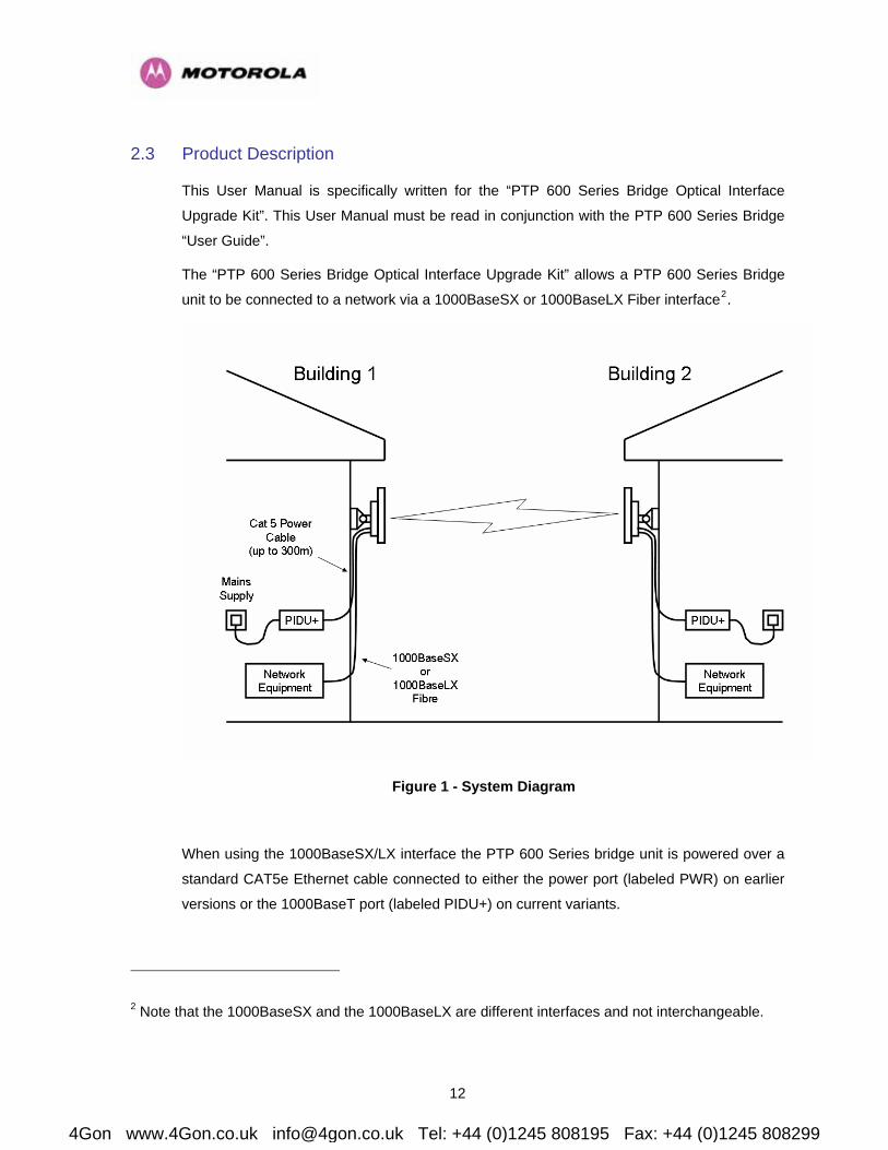
2.3 Product Description
This User Manual is specifically written for the “PTP 600 Series Bridge Optical Interface
Upgrade Kit”. This User Manual must be read in conjunction with the PTP 600 Series Bridge
“User Guide”.
The “PTP 600 Series Bridge Optical Interface Upgrade Kit” allows a PTP 600 Series Bridge
unit to be connected to a network via a 1000BaseSX or 1000BaseLX Fiber interface2.
Figure 1 - System Diagram
When using the 1000BaseSX/LX interface the PTP 600 Series bridge unit is powered over a
standard CAT5e Ethernet cable connected to either the power port (labeled PWR) on earlier
versions or the 1000BaseT port (labeled PIDU+) on current variants.
2 Note that the 1000BaseSX and the 1000BaseLX are different interfaces and not interchangeable.
4Gon www.4Gon.co.uk [email protected] Tel: +44 (0)1245 808195 Fax: +44 (0)1245 808299

13
Earlier versions are identified by the fact that they do not have a “Mod Strike” label on the
back of the ODU. ODU units with a “Mod Record” label showing “1” or higher (Figure 2) are
powered via the 1000BaseT port.
Figure 2 - Mod Record label (Power over 1000BaseT Variant)
The PTP 600 Series Bridge implements Automatic Media Selection (AMS). If both
1000BaseSX/LX Fiber and 1000BaseT connections are present the PTP 600 Series Bridge
unit will use the 1000BaseSX/LX Fiber connection. If the fiber optic cable should fail the PTP
600 Series Bridge unit will fall back to the 1000BaseT connection.
NOTE: Although a distance in excess of 300m (984 feet) can be achieved over the Fiber
interface there is a restriction of 300m on the power cable feeding power to the 1000BaseT
port.
NOTE: If you require fall-back to the copper Ethernet cable you must restrict the length of the
copper Ethernet cable to 100m
4Gon www.4Gon.co.uk [email protected] Tel: +44 (0)1245 808195 Fax: +44 (0)1245 808299

14
3 Fiber Specification
There are two version of the “PTP 600 Series Bridge optical Interface Upgrade Kit” one
containing a 1000BaseSX (850nm) SFP Module and the other containing a 1000BaseLX
(1310nm) SFP Module.
The fiber optic cable and fiber optic cable terminations are not supplied as part of the kit.
The various Fiber optic cable specifications are shown in Table 4 and Table 5.
Core/Cladding (microns)
62.5/125 62.5/125 50/125 50/125
Mode Multi Multi Multi Multi
Units
Bandwidth at 850nm 160 200 400 500 MHz/km
Operating Distance 220 275 500 550 meters
Insertion Loss 2.38 2.6 3.37 3.56 dB
Table 4 - Fiber Specification 1000BaseSX (850nm) modules
Core/Cladding (microns)
62.5/125 50/125 50/125 10/125
Mode Multi Multi Multi Single
Units
Bandwidth at 1310nm 500 400 500 N/A MHz/km
Operating Distance 550 550 550 5000 meters
Insertion Loss 1.67 0.07 1.19 0.16 dB
Table 5 - Fiber Specification 1000BaseLX (1310nm) modules
4Gon www.4Gon.co.uk [email protected] Tel: +44 (0)1245 808195 Fax: +44 (0)1245 808299

15
4 Contents of the Upgrade Kit
The “PTP 600 Series Bridge Optical Upgrade Kit” contains the following items:
Description Quantity
SFP Optical Module - (1000BaseSX) or (1000BaseLX) - Figure 3, Figure 4 1
Extension Tube (complete with ‘O’ Ring seal) - Figure 5 1
Weatherproofing Gland - Figure 6 1
Instruction Manual (on CD) – This Document 1
License Key Instructions and ID Code 1
Table 6 - Contents of the Upgrade Kit
Figure 3 - SFP Optical Module – 1000BaseSX (850 nm)
Figure 4 - Optical Module – 1000BaseLX (1310 nm)
4Gon www.4Gon.co.uk [email protected] Tel: +44 (0)1245 808195 Fax: +44 (0)1245 808299

16
WARNING The SFP Optical Module is sensitive to ESD. Observe ESD handling procedures.
CAUTION The performance of 1000BaseSX/LX connections can be seriously affected by
dust build up. Keep all dust covers in place until just before the connection is to be made.
Figure 5 - Extension Tube
Figure 6 - Weatherproofing Gland
4Gon www.4Gon.co.uk [email protected] Tel: +44 (0)1245 808195 Fax: +44 (0)1245 808299
17
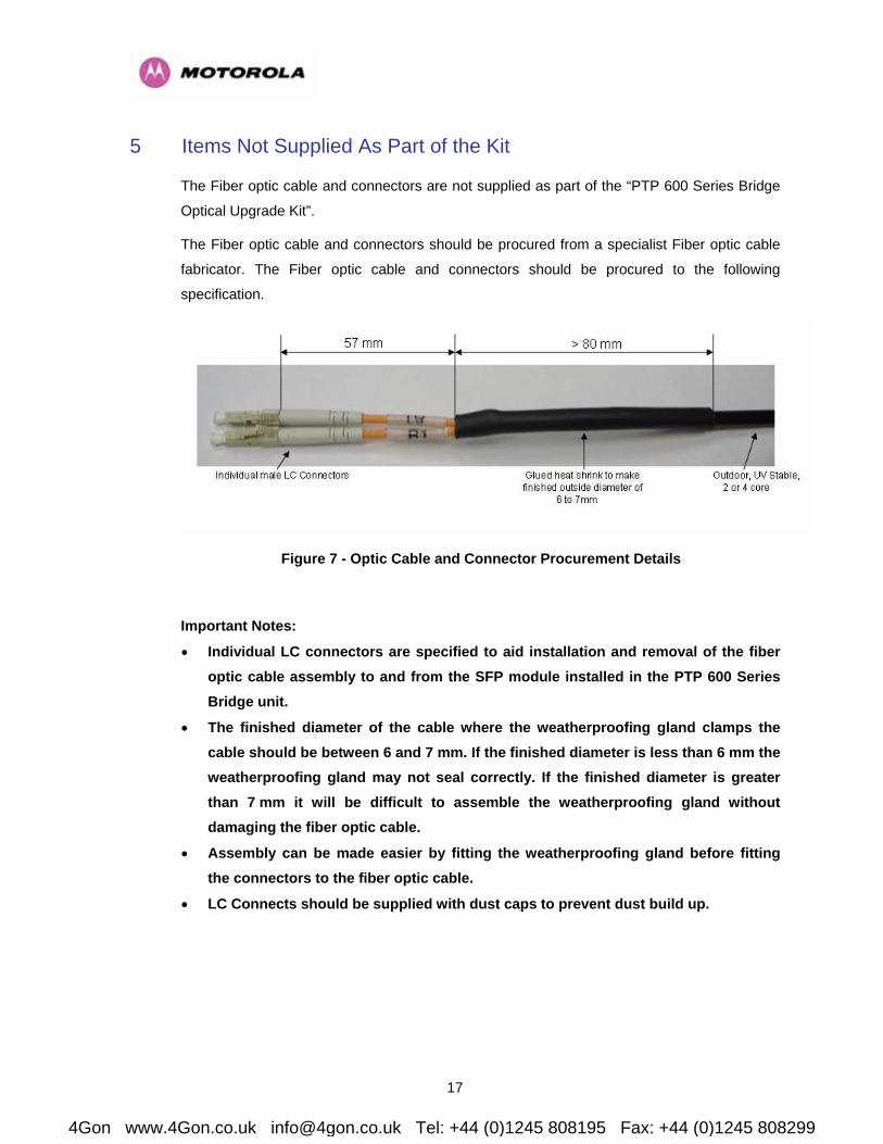
5 Items Not Supplied As Part of the Kit
The Fiber optic cable and connectors are not supplied as part of the “PTP 600 Series Bridge
Optical Upgrade Kit”.
The Fiber optic cable and connectors should be procured from a specialist Fiber optic cable
fabricator. The Fiber optic cable and connectors should be procured to the following
specification.
Figure 7 - Optic Cable and Connector Procurement Details
Important Notes:
• Individual LC connectors are specified to aid installation and removal of the fiber optic cable assembly to and from the SFP module installed in the PTP 600 Series Bridge unit.
• The finished diameter of the cable where the weatherproofing gland clamps the cable should be between 6 and 7 mm. If the finished diameter is less than 6 mm the weatherproofing gland may not seal correctly. If the finished diameter is greater than 7 mm it will be difficult to assemble the weatherproofing gland without damaging the fiber optic cable.
• Assembly can be made easier by fitting the weatherproofing gland before fitting the connectors to the fiber optic cable.
• LC Connects should be supplied with dust caps to prevent dust build up.
4Gon www.4Gon.co.uk [email protected] Tel: +44 (0)1245 808195 Fax: +44 (0)1245 808299
18
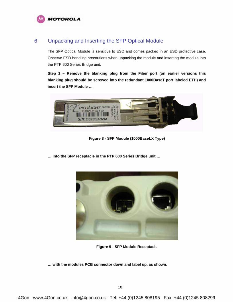
6 Unpacking and Inserting the SFP Optical Module
The SFP Optical Module is sensitive to ESD and comes packed in an ESD protective case.
Observe ESD handling precautions when unpacking the module and inserting the module into
the PTP 600 Series Bridge unit.
Step 1 – Remove the blanking plug from the Fiber port (on earlier versions this blanking plug should be screwed into the redundant 1000BaseT port labeled ETH) and insert the SFP Module …
Figure 8 - SFP Module (1000BaseLX Type)
… into the SFP receptacle in the PTP 600 Series Bridge unit …
Figure 9 - SFP Module Receptacle
… with the modules PCB connector down and label up, as shown.
4Gon www.4Gon.co.uk [email protected] Tel: +44 (0)1245 808195 Fax: +44 (0)1245 808299

19
Figure 10 - Inserting the SFP Module
Step 2 – Push home the module until it you feel it click into place.
Figure 11 – Pressing the SFP Module Home
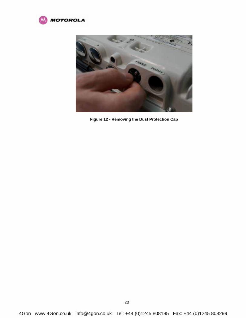
Step 3 – Then remove the optical dust protection cap.
4Gon www.4Gon.co.uk [email protected] Tel: +44 (0)1245 808195 Fax: +44 (0)1245 808299
20
Figure 12 - Removing the Dust Protection Cap
4Gon www.4Gon.co.uk [email protected] Tel: +44 (0)1245 808195 Fax: +44 (0)1245 808299

21
7 Connecting the Fiber Optic Cable
The Fiber optic cable assembly is very delicate. Extreme care should be taken when handling
to avoid damage.
CAUTION Care must be taken to ensure that the Fiber optic cable does not twist during
assembly. Extra care needs to be taken when fitting and tightening the weatherproofing
gland.
7.1 Installation
Step 1 - Thread the gland and extension tube over the Fiber optic cable as shown.
Figure 13 - Fiber Optic Cable Assembly
NOTE: It is preferable to thread the gland onto the Fiber optic cable before termination. It is
possible to thread the LC connectors through the gland by separating the rubber seal into its
component parts then stretching them open with a sleeve spreading tool.
4Gon www.4Gon.co.uk [email protected] Tel: +44 (0)1245 808195 Fax: +44 (0)1245 808299
22
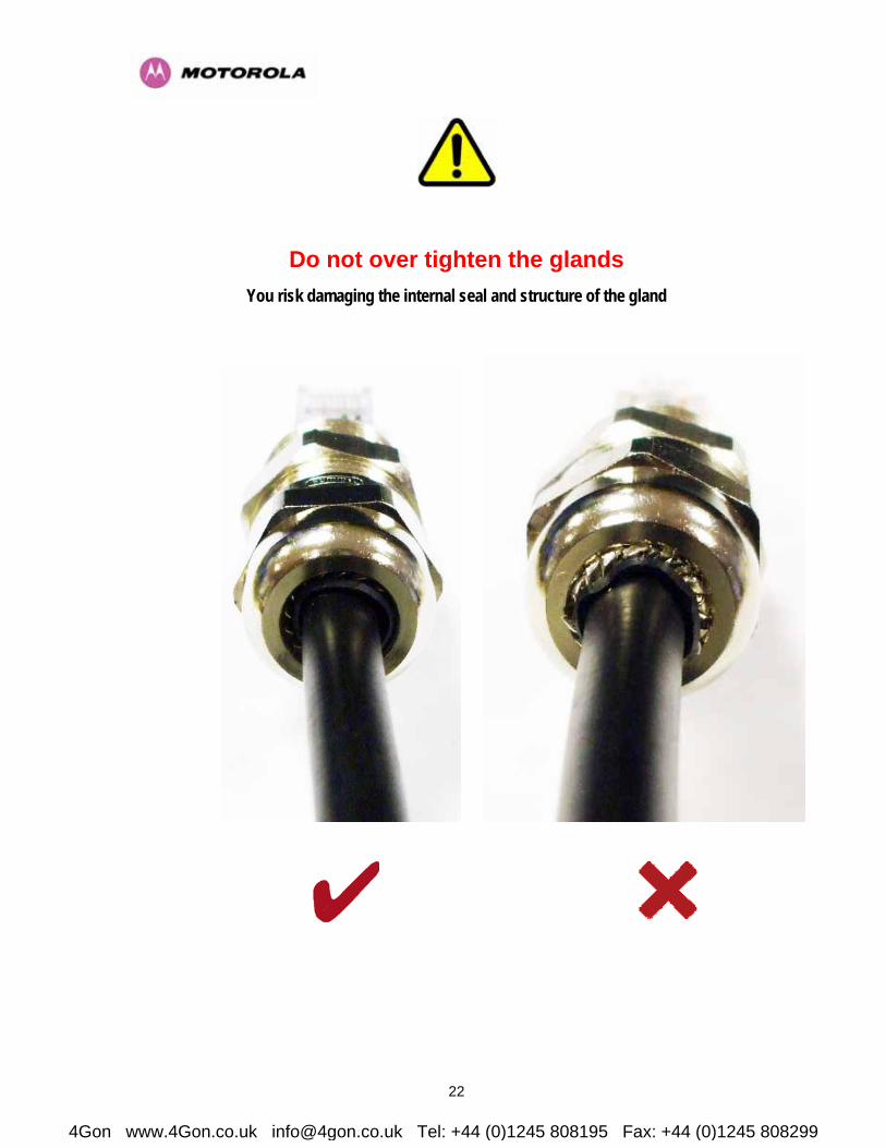
Do not over tighten the glands You risk damaging the internal seal and structure of the gland
4Gon www.4Gon.co.uk [email protected] Tel: +44 (0)1245 808195 Fax: +44 (0)1245 808299
23
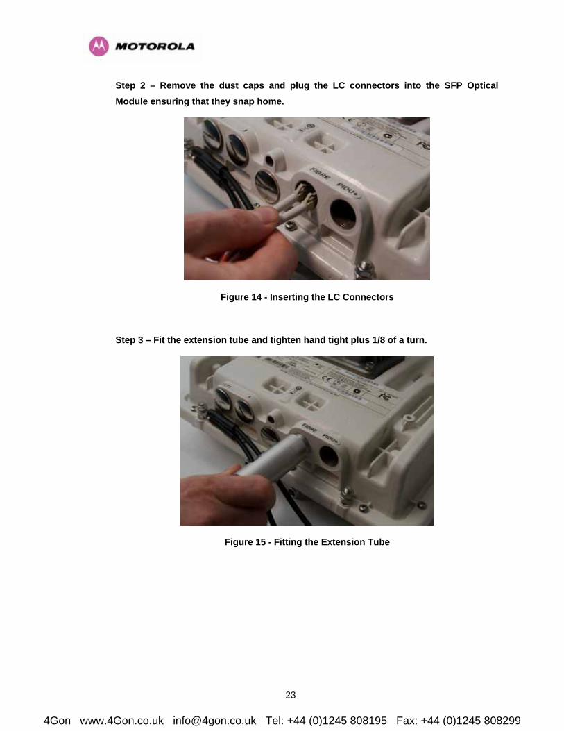
Step 2 – Remove the dust caps and plug the LC connectors into the SFP Optical Module ensuring that they snap home.
Figure 14 - Inserting the LC Connectors
Step 3 – Fit the extension tube and tighten hand tight plus 1/8 of a turn.
Figure 15 - Fitting the Extension Tube
4Gon www.4Gon.co.uk [email protected] Tel: +44 (0)1245 808195 Fax: +44 (0)1245 808299

24
Step 4 – Fit the Weatherproof Gland body and tighten hand tight plus 1/8 of a turn.
Figure 16 - Fitting the Weatherproof Gland Body
Step 6 – Fit the Weatherproof Gland Nut and tighten until the rubber part of the gland gives a good seal around the cable.
Figure 17 - Fitting the Weatherproof Gland Nut
4Gon www.4Gon.co.uk [email protected] Tel: +44 (0)1245 808195 Fax: +44 (0)1245 808299

25
Figure 18 - Completed Fiber Optic Assembly
Step 7 – On earlier versions it is necessary to a fit the spare blanking plug in the redundant port labeled ETH if not already fitted.
7.2 Removal
To remove the Fiber Optic Cable assembly the above procedure should be reversed. The LC
connectors are removed by pressing their release tabs. Special care should be taken when
removing the LC connectors to ensure that the release mechanism does not snag on the
threaded part of the hole in the PTP 600 Series Bridge enclosure.
4Gon www.4Gon.co.uk [email protected] Tel: +44 (0)1245 808195 Fax: +44 (0)1245 808299

26
8 Removing the SFP Optical Module
Before attempting to remove the SFP module carefully remove the cable assembly by
reversing the instructions in Section 7 “Connecting the Fiber Optic Cable”.
Then locate the plastic latches in the LC connectors and using a screwdriver push
downwards to release the cables as shown in Figure 19 and Figure 20.
Figure 19 - LC Connectors Latch Mechanism
Figure 20 - Release LC Connectors Latches
4Gon www.4Gon.co.uk [email protected] Tel: +44 (0)1245 808195 Fax: +44 (0)1245 808299
27
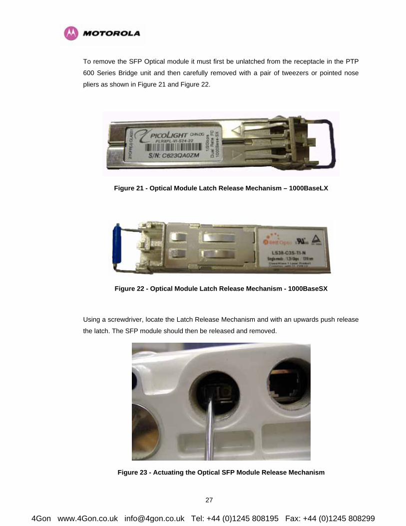
To remove the SFP Optical module it must first be unlatched from the receptacle in the PTP
600 Series Bridge unit and then carefully removed with a pair of tweezers or pointed nose
pliers as shown in Figure 21 and Figure 22.
Figure 21 - Optical Module Latch Release Mechanism – 1000BaseLX
Figure 22 - Optical Module Latch Release Mechanism - 1000BaseSX
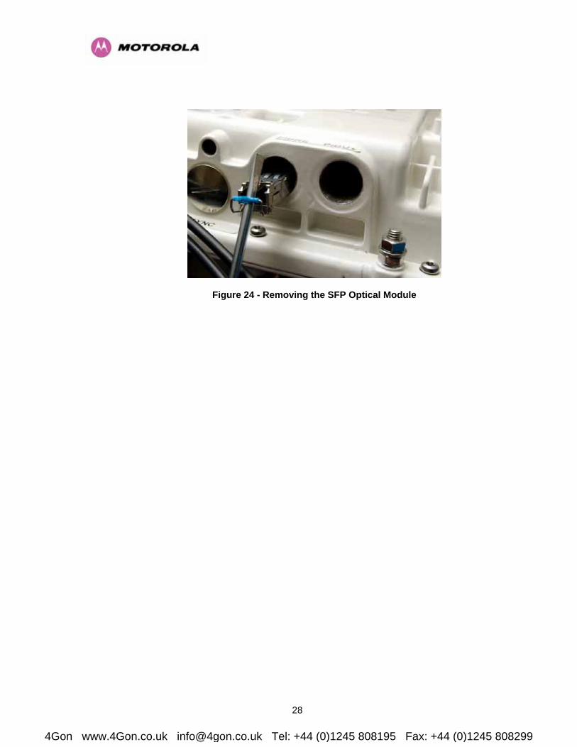
Using a screwdriver, locate the Latch Release Mechanism and with an upwards push release
the latch. The SFP module should then be released and removed.
Figure 23 - Actuating the Optical SFP Module Release Mechanism
4Gon www.4Gon.co.uk [email protected] Tel: +44 (0)1245 808195 Fax: +44 (0)1245 808299
28
Figure 24 - Removing the SFP Optical Module
4Gon www.4Gon.co.uk [email protected] Tel: +44 (0)1245 808195 Fax: +44 (0)1245 808299

29
9 Connecting the Power
For information on powering the PTP 600 Series Bridge System please refer to the “PTP 600
Series Bridge System User Manual”
The “PTP 600 Series Bridge System User Manual” must be followed for the following:
• Cable specification
• Cable Assembly
• Connection to the PTP 600 Series Bridge Power Indoor Unit Plus (PTP 600 Series Bridge
PIDU Plus)
• Lightning Protection
4Gon www.4Gon.co.uk [email protected] Tel: +44 (0)1245 808195 Fax: +44 (0)1245 808299
30
10 Configuring the Wireless Unit
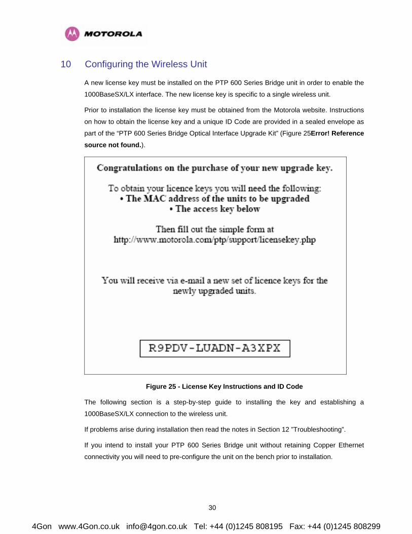
A new license key must be installed on the PTP 600 Series Bridge unit in order to enable the
1000BaseSX/LX interface. The new license key is specific to a single wireless unit.
Prior to installation the license key must be obtained from the Motorola website. Instructions
on how to obtain the license key and a unique ID Code are provided in a sealed envelope as
part of the “PTP 600 Series Bridge Optical Interface Upgrade Kit” (Figure 25Error! Reference source not found.).
Figure 25 - License Key Instructions and ID Code
The following section is a step-by-step guide to installing the key and establishing a
1000BaseSX/LX connection to the wireless unit.
If problems arise during installation then read the notes in Section 12 ”Troubleshooting”.
If you intend to install your PTP 600 Series Bridge unit without retaining Copper Ethernet
connectivity you will need to pre-configure the unit on the bench prior to installation.
4Gon www.4Gon.co.uk [email protected] Tel: +44 (0)1245 808195 Fax: +44 (0)1245 808299

31
Step 1 – Connect to the PTP 600 Series Bridge Unit
Using a standard CAT 5 patch cable, connect the PTP 600 Series Bridge unit to your network
and then switch the unit on. Direct your web browser to the IP address of the PTP 600 Series
Bridge unit.
Note: On earlier units this will be directly into the Outdoor Unit (ODU), on later units this will
be via the PTP 600 Series Bridge PIDU+.
If you have already installed your SFP Optical Module an alarm will be displayed which
indicates that an SFP module has been detected but that the current license key does not
include Fiber support (Figure 26). The absence of an alarm indicates that either the SFP
module is not connected correctly or that the current license key already includes Ethernet
Fiber support.
Figure 26 - PTP 600 Series Bridge Management Home Page
You may confirm that the SFP module has been connected correctly by viewing the "SFP
Configuration" menu which is described in Section 11.
4Gon www.4Gon.co.uk [email protected] Tel: +44 (0)1245 808195 Fax: +44 (0)1245 808299

32
Step 2 – Enter the new License Key (if not already valid)
Click on the "System Administration" menu on the navigation bar, the "License Key" menu
appears. Click on the "License Key" menu, you will be prompted to enter a system
administration password. Either enter the password or leave this field blank if no password
has been configured. Click the "Login" button to proceed. The software license key page is
shown in Figure 27.
Figure 27 - Software License Key Entry Page
4Gon www.4Gon.co.uk [email protected] Tel: +44 (0)1245 808195 Fax: +44 (0)1245 808299

33
If the "Capability summary" table includes a row with the title "Ethernet Fiber Support" then
your unit already supports Fiber connection as shown in Figure 28.
Figure 28 - License Key Page with Fiber support
Make a note of your current license key. If you retain this key you may use it to revert the
wireless unit to its current configuration.
The key comprises four, four digit hexadecimal numbers separated by three hyphens. Enter
the key exactly as it is written in the email sent as a result of registering the unique ID code
and MAC address on the Motorola website. Having entered the license key, press the
validate license key button.
If the subsequent web page includes the message "ERROR Invalid License Key" then use
the back button and re-enter a valid license key string. If the license key format is incorrect
then you will be notified by a pop-up dialog box. In this case, dismiss the dialog box and re-
enter the license key. If your license key is not valid then contact your distributor.
Having entered a valid license key, you will be prompted to reboot the wireless unit. Press the
"Reboot Wireless Unit" button and confirm the reboot in the dialog box which follows.
4Gon www.4Gon.co.uk [email protected] Tel: +44 (0)1245 808195 Fax: +44 (0)1245 808299

34
Step 3 – Check the configuration
After the unit has rebooted navigate to the “PTP 600 Series Bridge Management Home
Page”. The SFP alarm shown in Figure 26 should no longer be present.
Disconnect the CAT 5 network connection and make a 1000BaseSX connection between
your network and the SFP Optical Module. Navigate to the “Status Page” and confirm that the
"Ethernet Link Status" field is set to "Fiber Link Up" (Figure 29).
WARNING If your 1000BaseSX interface becomes active the PTP 600 Series Bridge unit will
immediately switch to the 1000BaseSX interface and no longer communicate over the
1000BaseT interface.
Figure 29 - System Status Page
Your wireless unit now supports Ethernet Fiber connection.
4Gon www.4Gon.co.uk [email protected] Tel: +44 (0)1245 808195 Fax: +44 (0)1245 808299
35
11 The SFP Configuration Menu
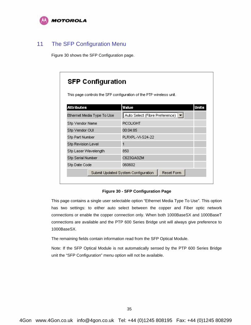
Figure 30 shows the SFP Configuration page.
Figure 30 - SFP Configuration Page
This page contains a single user selectable option “Ethernet Media Type To Use”. This option
has two settings: to either auto select between the copper and Fiber optic network
connections or enable the copper connection only. When both 1000BaseSX and 1000BaseT
connections are available and the PTP 600 Series Bridge unit will always give preference to
1000BaseSX.
The remaining fields contain information read from the SFP Optical Module.
Note: If the SFP Optical Module is not automatically sensed by the PTP 600 Series Bridge
unit the “SFP Configuration” menu option will not be available.
4Gon www.4Gon.co.uk [email protected] Tel: +44 (0)1245 808195 Fax: +44 (0)1245 808299

36
12 Troubleshooting
The unit does not respond when connected via the 1000BaseT connection.
• Check that the CAT 5 cables have been inserted correctly
• Ensure that the network settings on your PC are correct.
• If a fiber connection has been made to your network, then remove it. In the default
configuration the wireless unit will ignore the copper connection if a fiber connection is
available.
• Confirm that you have entered the IP address of the unit correctly into your browser.
• Refer to the PTP 600 Series Bridge System User Manual if a connection still cannot be
made.
The unit does not respond when connected via the 1000BaseSX connection.
• Browse to the unit over the wireless link (from a computer connected to the remote unit),
and check whether the “SFP Configuration” menu is available.
If the SFP Configuration menu is not available: Switch off the power to the wireless unit.
Remove and then replace the SFP module. Switch the unit back on and confirm that the
SFP Configuration menu is now available.
If the SFP Configuration menu is available: Check the “Ethernet Link Status” on the
“Status” page to see if it indicates a fault.
• Trying swapping the transmit and receive fibers
• Remove and remake both ends of the fiber connection ensuring that is no dust or other
debris contaminating the connections.
License key is incorrect.
• If the license key which you have is incorrect then contact your distributor or reseller.
ALARM: An SFP is installed but has been disabled because your license key does not include Fiber support.
• This alarm indicates that license key entered into the PTP 600 Series Bridge unit is
invalid.
ALARM: No Fiber link established but no LOS (i.e. an optical carrier is detected). Broken TX Fiber or link disabled at Fiber link partner?
• This alarm indicates that a signal is being received over the fiber interface but the
transmit fiber is broken or the receiver at the far end is disabled.
4Gon www.4Gon.co.uk [email protected] Tel: +44 (0)1245 808195 Fax: +44 (0)1245 808299
