cambium ptp 600 series point to point wireless … to point wireless solutions group cambium ptp 600...
TRANSCRIPT

POINT TO POINT WIRELESS SOLUTIONS GROUP
Cambium PTP 600 Series Point to Point Wireless Ethernet Bridges FIPS 140-2 Security Policy System Release 600-10-08-FIPS

Security Policy PTP 600-10-08
phn-4409 000v001 – January 2017 Page 2 of 30
CONTENTS 1 Introduction ............................................................................................................................ 5
1.1 Purpose ............................................................................................................................. 5
1.2 Anti Tamper Label Placement ......................................................................................... 6
1.3 Port Identification ............................................................................................................ 8
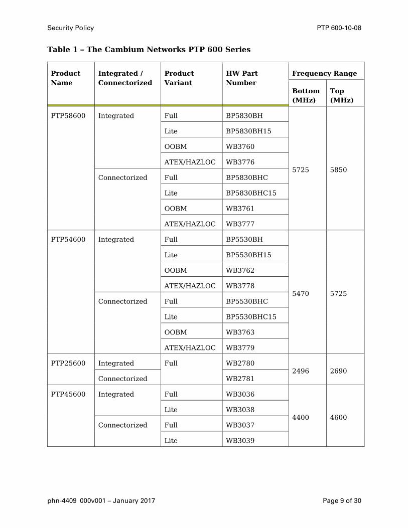
1.4 The PTP 600 Series .......................................................................................................... 8
1.5 References ...................................................................................................................... 11
1.6 Acronyms ........................................................................................................................ 12
2 Security Level ....................................................................................................................... 12
3 Mode of Operation ................................................................................................................ 13
3.1 Prerequisites for the Approved Mode of Operation ...................................................... 13
3.2 Configuring the Approved Mode of Operation .............................................................. 14
3.3 Checking that the unit is in the Approved Mode of Operation ..................................... 16
3.4 Approved and non-approved modes of operation ......................................................... 16
4 Ports and Interfaces .............................................................................................................. 18
5 Identification and Authentication Policy .............................................................................. 19
6 Access Control Policy ............................................................................................................ 19
6.1 Authentication Strength ................................................................................................ 19
6.2 Roles and Services ......................................................................................................... 20
6.3 Unauthenticated Services: ............................................................................................. 22
6.4 Service I/O Specification ............................................................................................... 23
6.5 Definition of Critical Security Parameters .................................................................... 24
6.6 CSP Encrypted by Key of Keys ...................................................................................... 26
6.7 Definition of Public Keys ................................................................................................ 26
6.8 Definition of CSP Modes of Access ................................................................................ 27
6.9 CSP Access Rights within Roles and Services .............................................................. 27
7 Operational environment ...................................................................................................... 27
8 Security Rules ....................................................................................................................... 27
8.1 Self Tests ........................................................................................................................ 27
8.2 Firmware Self Tests ....................................................................................................... 28
Security Policy PTP 600-10-08
phn-4409 000v001 – January 2017 Page 3 of 30
8.3 FIPS Integrity Test Error Indicators ............................................................................. 28
9 Identification of FIPS Mode of Operation ............................................................................ 28
10 Physical Security Policy ...................................................................................................... 28
10.1 FIPS Boundary and Frequency Variants ..................................................................... 29
11 Mitigation of Other Attacks Policy ..................................................................................... 29
TABLES Table 1 – The Cambium Networks PTP 600 Series ................................................................... 9
Table 2 – Module Security Level Specification ....................................................................... 12
Table 3 – FIPS approved and allowed algorithms ................................................................... 17
Table 4 – Management protocols in FIPS mode ...................................................................... 17
Table 5 – Ports and interfaces ................................................................................................. 18
Table 6 – Roles and authentication ......................................................................................... 19
Table 7 – Role-based services and CSP access ....................................................................... 21
Table 8 – Authenticated services ............................................................................................. 22
Table 9 – Unauthenticated services ........................................................................................ 22
Table 10 – Specification of service inputs and outputs........................................................... 23
FIGURES Figure 1 – PTP 600 Wireless Units ............................................................................................ 6
Figure 2 – Anti-tamper label placement .................................................................................... 6
Figure 3 – Port identification ..................................................................................................... 8
Figure 4 – Connectorized PTP 600 Unit .................................................................................. 10
Figure 5 – Integrated PTP 600 Unit ........................................................................................ 11
Figure 6 – Indication of FIPS 140-2 capability ........................................................................ 13


Security Policy PTP 600-10-08
phn-4409 000v001 – January 2017 Page 5 of 30
1 INTRODUCTION
1.1 Purpose This non-proprietary document describes the security policy for Cambium Networks PTP
600 Series Point to Point Wireless Ethernet Bridges.
The Cambium Networks PTP 600 Series (hereafter the PTP 600 or PTP 600 Series) devices
are multi-chip standalone cryptographic modules encased in hard opaque commercial grade
metal cases. Operating in the 2.5, 4.5, 4.8, 4.9, 5.5 and 5.9 GHz frequency bands at
Ethernet data rates up to 300 Mbps, the systems are designed for virtually any environment
– non-line-of-sight, line-of-sight, and high interference – where high throughput is a major
requirement and/or single or dual T1/E1 capability is needed.
Through Cambium Network’s unique combination of technologies, PTP 600 Series solutions
enhance link performance in a variety of applications, including T1 replacement, Voice-
over-IP, video surveillance, distance learning, telemedicine, and high-speed backhaul.
The cryptographic boundary of the wireless unit is the unit’s external casing. There are two
product variants that have a different casing arrangement. Firstly the Integrated wireless
units as the name suggests has an integrated RF antenna. The second product variant is
named the Connectorized product variant which is identical to the Integrated product
except the antenna is replaced by a metal plate with two ‘N’ type RF connectors. For the
purposes of FIPS Approval the integrated antenna is excluded from the cryptographic
boundary.
The purpose of this security policy is to validate the Cambium PTP 600 Series (HW P/Ns
BP5830BHC, BP5830BHC15, BP5530BHC, BP5530BHC15, WB2781,WB3039, WB3037,
WB3092, WB3094, WB3387, WB3389, WB3222, BP5830BH, BP5830BH15, BP5530BH,
BP5530BH15, WB2780, WB3036, WB3038, WB3091, WB3093, WB3386, WB3388, WB3221,
WB3760, WB3761, WB3762, WB3763, WB3776, WB3777, WB3778, and WB3779 with
Firmware Versions PTP600-10-00-FIPS, PTP600-10-05-FIPS, PTP600-10-07-FIPS and
PTP600-10-08-FIPS submitted for FIPS 140-2 Level 2 validation.

Security Policy PTP 600-10-08
phn-4409 000v001 – January 2017 Page 6 of 30
Figure 1 – PTP 600 Wireless Units
Integrated Connectorized
1.2 Anti Tamper Label Placement Figure 2 – Anti-tamper label placement
Connectorized PTP 600 Unit (2 Labels Wrapping around Enclosure Edge)
Left (vertical)
Top (horizontal)
#1 #2

Security Policy PTP 600-10-08
phn-4409 000v001 – January 2017 Page 7 of 30
Integrated PTP 600 Unit (2 Labels on Underside)
Note: The two anti-tamper labels on the Integrated module are affixed around the edge of
the cover so that they make contact with both metal surfaces.
The anti-tamper labels must be installed for the module to operate in a FIPS Approved
mode of operation.
The module is delivered to the operator with the anti-tamper labels applied. A hardware
security upgrade kit containing additional anti-tamper labels may be obtained from
Cambium Networks. The hardware security upgrade kit is P/N WB3593.
The Crypto-Officer is the role responsible for:
• Securing and controlling any unused anti-tamper labels.
• Controlling and observing module reconfigurations (i.e., firmware updates) during
which the anti-tamper labels would be removed and reinstalled to verify that the
module remains secure during such updates and that it is returned to the FIPS
Approved mode after the updates are complete.
Before the anti-tamper labels can be replaced, the module surface must be prepared using
the following procedure:
All positions where labels are to be placed must be cleaned with a cloth wetted with
Isopropyl Alcohol (IPA)1 before the labels can placed.
1 IPA is a solvent/cleaner.
#2
#1

Security Policy PTP 600-10-08
phn-4409 000v001 – January 2017 Page 8 of 30
The glued side of the label must not be touched during the label placement. If it is
inevitable, tweezer must be used for handling.
Cambium recommends that the operator inspects the integrity of the anti-tamper labels a
minimum of every 30 days.
1.3 Port Identification Figure 3 – Port identification
The module ports are as follows:
• E1/T1: RJ45 socket for optional E1 or T1 network connection.
• AUX: Auxiliary RJ45 socket for out-of-band management interface (Management Port)
or GPS connection (Sync Port).
• FIBER: Fiber optic socket for optional network connection. Subsequently referred to
as the Fiber Data Port.
• PIDU+: RJ45 socket for connecting to power supply and network via the PIDU Plus.
Referred to as the Copper Data Port.
1.4 The PTP 600 Series The product family consists of integrated (RF antenna built in) and connectorized (RF
connectors to external antennas) variants. In addition each product variant can be
purchased as a sub-variant of full or lite (when the full version offers 50% more Ethernet
throughput for the same RF propagation conditions. And finally the PTP 600 can be
purchased in the following frequency variants: 2.5, 4.5, 4.8, 4.9, 5.4, 5.5, 5.8 and 5.9 GHz.
Table 1 lists the frequency ranges supported by each PTP 600 module.
Security Policy PTP 600-10-08
phn-4409 000v001 – January 2017 Page 9 of 30
Table 1 – The Cambium Networks PTP 600 Series
Product Name
Integrated / Connectorized
Product Variant
HW Part Number
Frequency Range
Bottom (MHz)
Top (MHz)
PTP58600 Integrated Full BP5830BH
5725 5850
Lite BP5830BH15
OOBM WB3760
ATEX/HAZLOC WB3776
Connectorized Full BP5830BHC
Lite BP5830BHC15
OOBM WB3761
ATEX/HAZLOC WB3777
PTP54600 Integrated Full BP5530BH
5470 5725
Lite BP5530BH15
OOBM WB3762
ATEX/HAZLOC WB3778
Connectorized Full BP5530BHC
Lite BP5530BHC15
OOBM WB3763
ATEX/HAZLOC WB3779
PTP25600 Integrated Full WB2780 2496 2690
Connectorized WB2781
PTP45600 Integrated Full WB3036
4400 4600 Lite WB3038
Connectorized Full WB3037
Lite WB3039

Security Policy PTP 600-10-08
phn-4409 000v001 – January 2017 Page 10 of 30
Product Name
Integrated / Connectorized
Product Variant
HW Part Number
Frequency Range
Bottom (MHz)
Top (MHz)
PTP48600 Integrated Full WB3386
4700 5000 Lite WB3388
Connectorized Full WB3387
Lite WB3389
PTP49600 Integrated Full WB3221 4900 4990
Connectorized Full WB3222
PTP59600 Integrated Full WB3091
5825 5925 Lite WB3093
Connectorized Full WB3092
Lite WB3094
Figure 4 – Connectorized PTP 600 Unit

Security Policy PTP 600-10-08
phn-4409 000v001 – January 2017 Page 11 of 30
Figure 5 – Integrated PTP 600 Unit
1.5 References (a) FIPS PUB 186-2, Federal Information Processing Standards Publication 186-2, Feb
2000.
(b) FIPS PUB 180-3, Federal Information Processing Standards Publication 180-3,
October 2008.
(c) FIPS PUB 140-2, Federal Information Processing Standards Publication 140-2, 25th
May 2001.
(d) FIPS PUB 197, Federal Information Processing Standards Publication 192, 26th
November 2001.
(e) DSAVS, Digital Signature Algorithm Validation Suite, 10th March 2004.
(f) PTP 600 Series User Guide. phn-0896 007v001, Monday 30th June 2008
(g) X.680, ASN.1 Encoding Rules: specification of Basic Encoding Rules (BER), Canonical
Encoding Rules (CER) and Distinguished Encoding Rules (DER), (07/02)
(h) PKCS #8: Private-Key Information Syntax Standard, Version 1.2, November 1, 1993
(i) PKCS #1: Public Key Cryptography Standards (PKCS), Version 2,1, June 14 2001
(j) RFC 4346, The Transport Layer Security Protocol version 1.0, April 2006.
(k) NIST SP 800-90 Recommendation for Random Number Generators Using
Deterministic Random Bit Generators. March 2007.
Security Policy PTP 600-10-08
phn-4409 000v001 – January 2017 Page 12 of 30
(l) NIST Special Publication 800-131B - Transitions: Validation of Transitioning
Cryptographic Algorithm and Key Lengths, February 2011
1.6 Acronyms CA Certification Authority
CO Cryptographic Officer
CSP Critical Security Parameter
DER Distinguished Encoding Rules
DES Data Encryption Standard
DSA Digital Signature Algorithm
FIPS Federal Information Processing Standard
HMAC Hashed Message Authentication Code
KAT Known Answer Test
PTP Point to Point
SA System Administrator
SNMP Simple Network Management Protocol
TLS Transport Layer Security
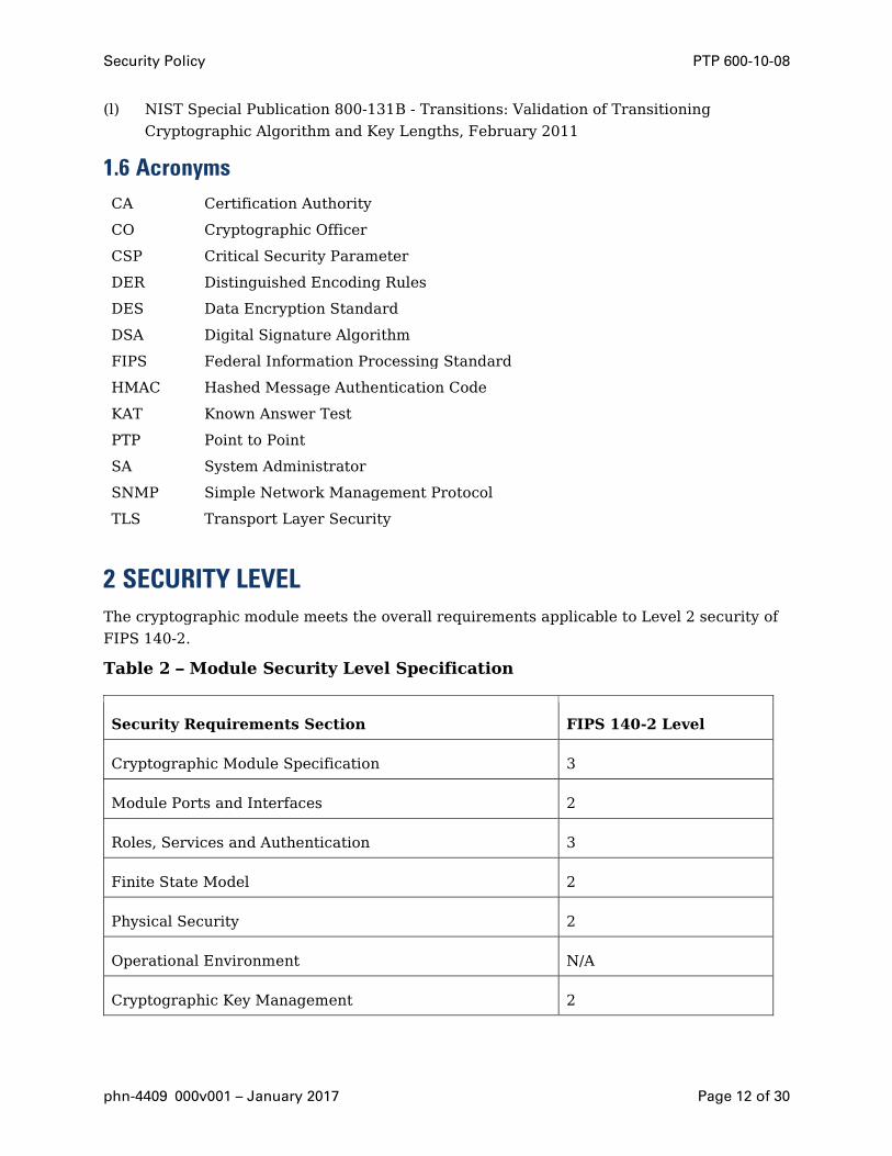
2 SECURITY LEVEL The cryptographic module meets the overall requirements applicable to Level 2 security of
FIPS 140-2.
Table 2 – Module Security Level Specification
Security Requirements Section FIPS 140-2 Level
Cryptographic Module Specification 3
Module Ports and Interfaces 2
Roles, Services and Authentication 3
Finite State Model 2
Physical Security 2
Operational Environment N/A
Cryptographic Key Management 2
Security Policy PTP 600-10-08
phn-4409 000v001 – January 2017 Page 13 of 30
Security Requirements Section FIPS 140-2 Level
EMI/EMC 2
Self-Tests 2
Design Assurance 3
Mitigation of Other Attacks N/A
3 MODE OF OPERATION
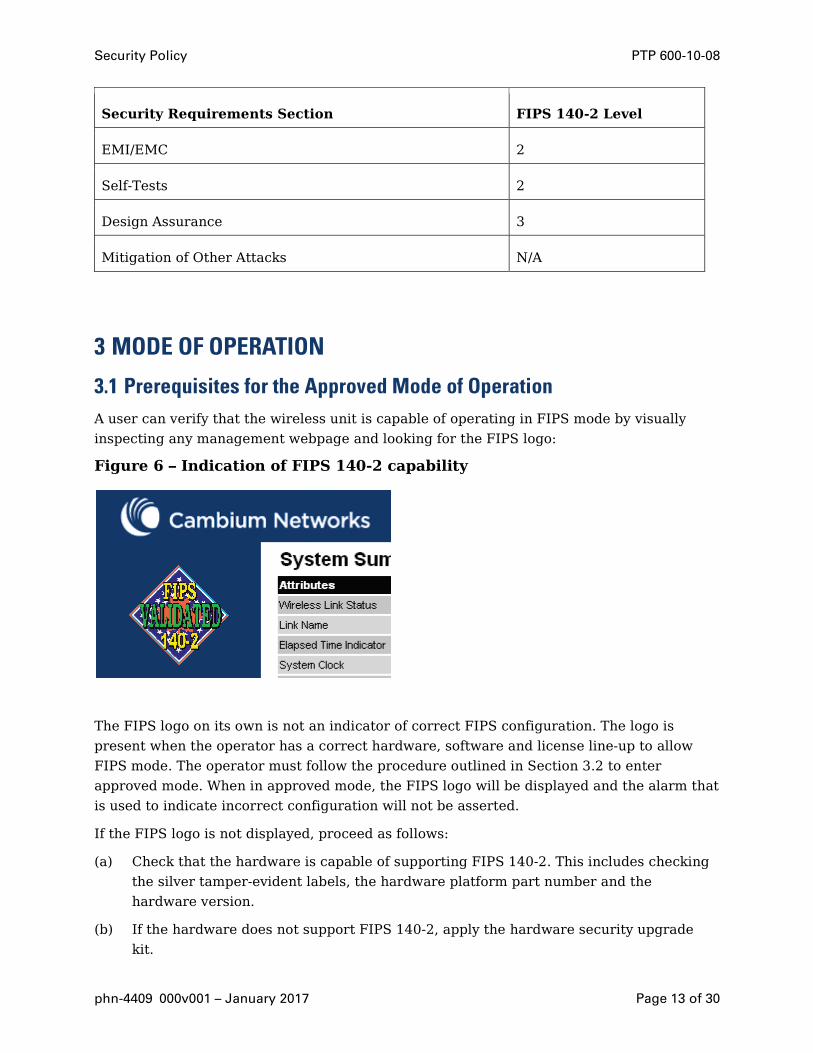
3.1 Prerequisites for the Approved Mode of Operation A user can verify that the wireless unit is capable of operating in FIPS mode by visually
inspecting any management webpage and looking for the FIPS logo:
Figure 6 – Indication of FIPS 140-2 capability
The FIPS logo on its own is not an indicator of correct FIPS configuration. The logo is
present when the operator has a correct hardware, software and license line-up to allow
FIPS mode. The operator must follow the procedure outlined in Section 3.2 to enter
approved mode. When in approved mode, the FIPS logo will be displayed and the alarm that
is used to indicate incorrect configuration will not be asserted.
If the FIPS logo is not displayed, proceed as follows:
(a) Check that the hardware is capable of supporting FIPS 140-2. This includes checking
the silver tamper-evident labels, the hardware platform part number and the
hardware version.
(b) If the hardware does not support FIPS 140-2, apply the hardware security upgrade
kit.
Security Policy PTP 600-10-08
phn-4409 000v001 – January 2017 Page 14 of 30
(c) Check the capability summary in the Software License Key page to ensure that the
current license key supports AES and FIPS 140-2. If necessary, obtain an access key
and generate a new license key.
(d) Check the installed software version in the System Status page to ensure that the
software image is FIPS validated. If necessary, upgrade to the latest FIPS validated
image.
3.2 Configuring the Approved Mode of Operation If the FIPS logo is displayed, the approved mode of operation can be configured using the
Security Configuration Wizard.
3.2.1 Obtaining cryptographic material
Before starting the Security Configuration Wizard, ensure that the following cryptographic
material has been generated using a FIPS-approved cryptographic generator:
• Key Of Keys
• TLS Private Key and Public Certificates
• Entropy Input
• Wireless Link Encryption Key for AES
3.2.2 Starting Security Configuration Wizard
To start the wizard, proceed as follows:
(a) Select menu option Security. The Security Configuration Wizard page is displayed.
(b) Review the summary of HTTPS/TLS security related parameters.
(c) If any updates are required, select Continue to Security Wizard.
3.2.3 Step 1: Enter key of keys
To enter the Key Of Keys via the Security Wizard, proceed as follows:
(a) The Step 1: Enter Key of Keys page is displayed.
(b) Enter the generated key of keys in both the Key Of Keys and Confirm Key Of Keys
fields.
(c) Select Next.
3.2.4 Step 2: TLS private key and public certificate
To enter the TLS Private Key and Public Certificate via the Security Wizard, proceed as
follows:
(a) The Step 2: TLS Private Key and Public Certificate page is displayed.

Security Policy PTP 600-10-08
phn-4409 000v001 – January 2017 Page 15 of 30
(b) If a valid TLS private key exists, then an SHA-256 thumbprint of the key is displayed.
If this key is correct, then take no action. Otherwise, select Browse and select the
generated private key file (.der).
(c) If a valid TLS public certificate exists, then an SHA-256 thumbprint of the certificate
is displayed. If this certificate is correct, then take no action. Otherwise, select
Browse and select the generated certificate file (.der).
(d) Select Next.
3.2.5 Step 3: User security banner
To enter the user security banner via the Security Wizard, proceed as follows:
(a) The Step 3: User Security Banner page is displayed.
(b) Update the User Defined Security Banner field.
(c) Select Next.
3.2.6 Step 4: Random number entropy input
To enter the Entropy Input via the Security Wizard, proceed as follows:
(a) The Step 4: Random Number Entropy Input page is displayed.
(b) If valid entropy input exists, then an SHA-256 thumbprint of the input is displayed. If
this input is correct, then take no action. Otherwise, enter the generated input in the
Entropy Input and Confirm Entropy Input fields. If the two values are not identical, an
error message is displayed.
(c) Select Next.
3.2.7 Step 5: Enter the wireless link encryption key
To enter the wireless link encryption key via the Security Wizard, proceed as follows:
(a) The Step 5: Enter The Wireless Link Encryption Key page is displayed.
(b) Select the applicable value in the Encryption Algorithm field.
(c) If a valid encryption key exists, then an SHA-256 thumbprint of the key is displayed. If
this key is correct, then take no action. Otherwise, enter the generated key in the
Wireless Link Encryption Key and Confirm Wireless Link Encryption Key fields. If the
two values are not identical, an error message is displayed.
(d) Select Next.
3.2.8 Step 6: HTTP and Telnet settings
To configure HTTP and Telnet via the Security Wizard, proceed as follows:
(a) The Step 6: HTTP and Telnet Settings page is displayed.
Security Policy PTP 600-10-08
phn-4409 000v001 – January 2017 Page 16 of 30
(b) Review and update the HTTP and Telnet attributes. If the unit is required to operate
in FIPS 140-2 secure mode, HTTP, Telnet and SNMP Control must all be disabled.
(c) Select Next.
3.2.9 Step 7: Commit security configuration
Review all changes that have been made in the Security Wizard. To ensure that the changes
take effect, select Commit Security Configuration. The unit reboots and the changes
take effect.
3.3 Checking that the unit is in the Approved Mode of Operation The unit is ready to operate in FIPS 140-2 secure mode when both of the following
conditions apply:
• The FIPS 140-2 capability logo is displayed in the navigation bar.
• The FIPS Operational Mode Alarm is not present in the Home page.
If the FIPS 140-2 capability logo is not displayed in the navigation bar, then return to
Section 3.1 and check that all prerequisites are fulfilled.
If the FIPS 140-2 Operational Mode Alarm is present in the Home page, take action
depending upon the alarm setting as follows:
• If the alarm is ‘FIPS mode is not configured’, then return to Section 3.2 and check
that all Security Wizard settings are correct for FIPS 140-2.
• If the alarm is ‘FIPS mode is configured, but not active’, then return to Section 3.2.8
and set the following attributes to ‘No’:
• HTTP Access Enabled
• Telnet Access Enabled
• SNMP Control of HTTP And Telnet
3.4 Approved and non-approved modes of operation
3.4.1 Approved mode of operation
In the non-approved non-FIPS mode of operation it is possible to use all the approved
algorithms of FIPS mode and also to use in the clear management protocols. No CSPs are
shared between these modes of operation. A zeroize CSPs is forced if a user causes the unit
to transit between modes.
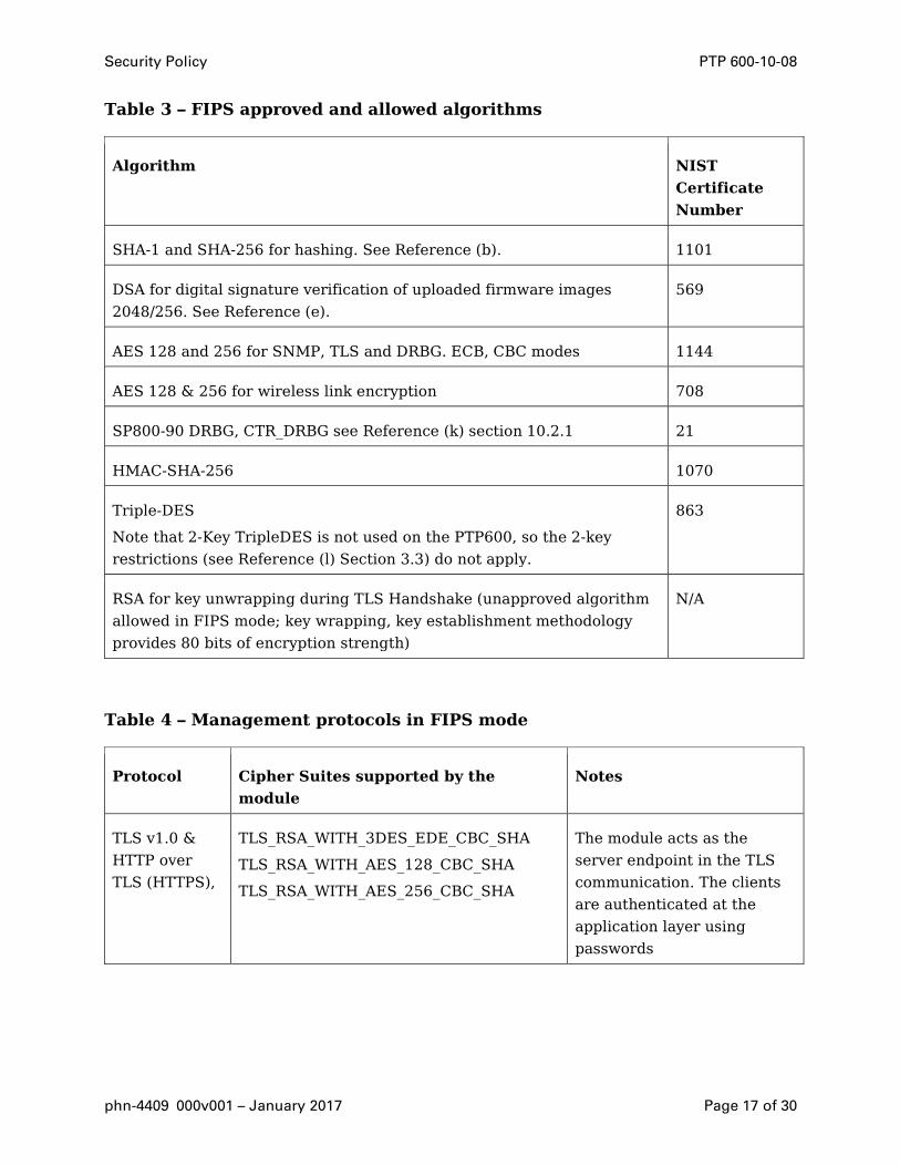
In FIPS mode, the cryptographic module only supports FIPS Approved and allowed
algorithms as follows:
Security Policy PTP 600-10-08
phn-4409 000v001 – January 2017 Page 17 of 30
Table 3 – FIPS approved and allowed algorithms
Algorithm NIST
Certificate
Number
SHA-1 and SHA-256 for hashing. See Reference (b). 1101
DSA for digital signature verification of uploaded firmware images
2048/256. See Reference (e).
569
AES 128 and 256 for SNMP, TLS and DRBG. ECB, CBC modes 1144
AES 128 & 256 for wireless link encryption 708
SP800-90 DRBG, CTR_DRBG see Reference (k) section 10.2.1 21
HMAC-SHA-256 1070
Triple-DES
Note that 2-Key TripleDES is not used on the PTP600, so the 2-key
restrictions (see Reference (l) Section 3.3) do not apply.
863
RSA for key unwrapping during TLS Handshake (unapproved algorithm
allowed in FIPS mode; key wrapping, key establishment methodology
provides 80 bits of encryption strength)
N/A
Table 4 – Management protocols in FIPS mode
Protocol Cipher Suites supported by the
module
Notes
TLS v1.0 &
HTTP over
TLS (HTTPS),
TLS_RSA_WITH_3DES_EDE_CBC_SHA
TLS_RSA_WITH_AES_128_CBC_SHA
TLS_RSA_WITH_AES_256_CBC_SHA
The module acts as the
server endpoint in the TLS
communication. The clients
are authenticated at the
application layer using
passwords
Security Policy PTP 600-10-08
phn-4409 000v001 – January 2017 Page 18 of 30
3.4.2 Non-FIPS modes of operation
The following algorithms and protocols are available in the Non-FIPS mode of operation:
• Custom RNG2
• HTTP
• Unencrypted Wireless
• RADIUS
• MD5
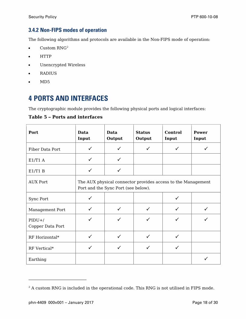
4 PORTS AND INTERFACES The cryptographic module provides the following physical ports and logical interfaces:
Table 5 – Ports and interfaces
Port Data
Input
Data
Output
Status
Output
Control
Input
Power
Input
Fiber Data Port
E1/T1 A
E1/T1 B
AUX Port The AUX physical connector provides access to the Management
Port and the Sync Port (see below).
Sync Port
Management Port
PIDU+/
Copper Data Port
RF Horizontal*
RF Vertical*
Earthing
2 A custom RNG is included in the operational code. This RNG is not utilised in FIPS mode.

Security Policy PTP 600-10-08
phn-4409 000v001 – January 2017 Page 19 of 30
* For connection of external antenna. Within the module boundary for the Connectorized
version; not exposed for the Integrated version.
5 IDENTIFICATION AND AUTHENTICATION POLICY The PTP 600 supports identity-based authentication. The following table outlines the roles
that can be assigned to each operator.
Table 6 – Roles and authentication
Role Type of Authentication Authentication Mechanism
Security Officer
(Crypto-Officer)
Username and password
verification
Username and password entered over a
TLS socket to the HTTPS server and
verified by wireless unit.
System
Administrator
Username and password
verification
Username and password entered over a
TLS socket to the HTTPS server and
verified by wireless unit.
Remote Username and
password verification
The username and password are passed
to a remote authentication server using
a secure TLS tunnel
Read-only user Username and password
verification
Username and password entered over a
TLS socket to the HTTPS server and
verified by wireless unit
Remote Username and
password verification
The username and password are passed
to a remote authentication server using
a secure TLS tunnel
6 ACCESS CONTROL POLICY
6.1 Authentication Strength In FIPS mode password complexity is enforced:
The complexity rules are:
The password must contain at least two characters for each of the four groups:
(a) lowercase letter

Security Policy PTP 600-10-08
phn-4409 000v001 – January 2017 Page 20 of 30
(b) uppercase letter
(c) decimal numerals
(d) special characters3
The password must have a minimum length of 10 characters
The passwords must not contain the user’s username.
The maximum number of repeated characters in a password is 2.
When passwords are changed at least four distinct character MUST change
Password must not be reused for the next 10 passwords.
Only three authentication attempts are permitted for any user within any one minute
period.
A password with minimum complexity can be constructed by selecting, 2 lowercase, 2
uppercase, 2 special characters and 4 numeric characters. The strength of this combination
is calculated as follows:
124222 107.41
101.
321.
261.
261
×==p
Test Strength
1 in 100,000 in any minute Pass strength is 1 in 4.7 x 10¹²
1 in 1,000,000 at any attempt Pass strength is 1 in 1.5 x 10¹²
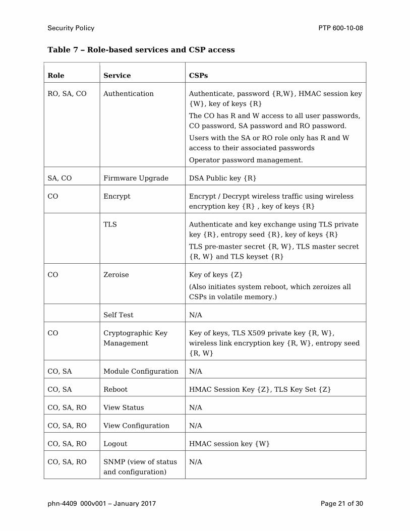
6.2 Roles and Services The services available to authenticated users are summarised in Table 7 and Table 8. These
roles and services are also available in non-FIPS mode.
Table 7 also identifies the CSP access type for each CSP in braces after each CSP. {R}ead,
{W}rite and {Z}eroize.
3 Allowable special characters are: !"#$%&'()*+,-./:;<=>?@[\]^_`{|}~
Security Policy PTP 600-10-08
phn-4409 000v001 – January 2017 Page 21 of 30
Table 7 – Role-based services and CSP access
Role Service CSPs
RO, SA, CO Authentication Authenticate, password {R,W}, HMAC session key
{W}, key of keys {R}
The CO has R and W access to all user passwords,
CO password, SA password and RO password.
Users with the SA or RO role only has R and W
access to their associated passwords
Operator password management.
SA, CO Firmware Upgrade DSA Public key {R}
CO Encrypt Encrypt / Decrypt wireless traffic using wireless
encryption key {R} , key of keys {R}
TLS Authenticate and key exchange using TLS private
key {R}, entropy seed {R}, key of keys {R}
TLS pre-master secret {R, W}, TLS master secret
{R, W} and TLS keyset {R}
CO Zeroise Key of keys {Z}
(Also initiates system reboot, which zeroizes all
CSPs in volatile memory.)
Self Test N/A
CO Cryptographic Key
Management
Key of keys, TLS X509 private key {R, W},
wireless link encryption key {R, W}, entropy seed
{R, W}
CO, SA Module Configuration N/A
CO, SA Reboot HMAC Session Key {Z}, TLS Key Set {Z}
CO, SA, RO View Status N/A
CO, SA, RO View Configuration N/A
CO, SA, RO Logout HMAC session key {W}
CO, SA, RO SNMP (view of status
and configuration)
N/A

Security Policy PTP 600-10-08
phn-4409 000v001 – January 2017 Page 22 of 30
Table 8 – Authenticated services
Service Role Purpose
Authentication CO, SA, RO Authenticate user logins
Operator password management
Firmware Upgrade CO, SA Upgrade operational firmware
Encrypt CO Encrypt / Decrypt wireless traffic
Zeroise CO Zeroise Key of Keys (Also initiates system reboot, which
zeroizes all CSPs in volatile memory.)
Cryptographic Key
management
CO Cryptographic key data entry and CSP zeroisation
Module
Configuration
CO A selection of standard wireless unit configuration
settings
Reboot CO Reboot the wireless unit
View Status SA, CO, RO View module status including hardware and firmware
versions
View
Configuration
RO, SA, CO View all system administrative configuration
Logout RO, SA, CO Invalidate any previously HMAC signed cookies by
regenerating the HMAC session key
6.3 Unauthenticated Services: The services available to unauthenticated users are summarised in Table 9.
Table 9 – Unauthenticated services
Service Role Purpose
Self Test - This service executes a suite of cryptographic self tests as
required by FIPS 140-2 level 2. (Power up self test)

Security Policy PTP 600-10-08
phn-4409 000v001 – January 2017 Page 23 of 30
Service Role Purpose
TLS - Implement the TLS secure communication protocol
Syslog - Service to log system events to an external server
SNMP - View status and configuration using the SNMP management
protocol. It is important to note that no CSPs are accessible
using the SNMP protocol
View Status - View wireless performance status
6.4 Service I/O Specification Table 10 – Specification of service inputs and outputs
Service Control Input Data Input Data Output Status Output
Authentication Authentication
request
Username &
password
Or
HMAC signed
cookie
HMAC signed
cookie
Status OK if
username and
password match
plain text
username and
password CSP
Firmware
Upgrade
Upgrade
request
Plaintext
header + BZIP2
compressed
image
DSA
verification ‘v’
vector
Status OK if ‘v’ =
‘r’
Zeroise Zeroise Request None None True if key of keys
removed from
non-volatile
storage and
system reboot
Self Test System reboot Self Test keys
and test vectors
None True if algorithm
self test
successful.
Otherwise false
Cryptographic
Key
Data Entry Key of Keys,
TLS Private
None True if key
correctly

Security Policy PTP 600-10-08
phn-4409 000v001 – January 2017 Page 24 of 30
Service Control Input Data Input Data Output Status Output
Management key, TLS public
certificate,
entropy seed,
passwords
validated.
Otherwise false
Module
Configuration
Data Entry Wireless
Configuration
None True if
configuration
parameters
correctly
validated.
Otherwise false
Reboot Data Entry None None None
View Status View Status
Request
None Status
information
None
View
Configuration
View
Configuration
Request
None Configuration
Information
None
Logout Logout Request None None OK
6.5 Definition of Critical Security Parameters The following CSPs and public keys are contained in the modules FLASH memory. These
are NOT read into SDRAM by the FIPS module.
6.5.1 Key of Keys
The key of keys is stored as a 128/256-bit AES key and is stored in the CSP FLASH bank.
The key of keys is read during the DMGR initialisation procedure and the key expansion is
stored in SDRAM. All DMGR attributes that are marked as CSPs are encrypted/decrypted as
they are written/read from the configuration FLASH banks using the key expansion.
The integrity of the key of keys is validated by the user with a CRC32.
The key of keys can be configured or erased by a user with the security officer role.
6.5.2 TLS X509 Private Key
TLS private key is used by the HTTPS server. The private key is designated as a DMGR CSP
and is encrypted using the key of keys.

Security Policy PTP 600-10-08
phn-4409 000v001 – January 2017 Page 25 of 30
A key size of 1024-bits is supported
Entered via a secure webpage upload
Generated by a FIPS approved algorithm outside the module
Validity checked by performing a modulus check on private and associated public
certificate.
The X.509 private key can be configured or erased by a user with the security officer role.
6.5.3 RNG Entropy
SP800-90 DRBG entropy string is used by the TLS stack and other random processes. The
entropy string is designated as a DMGR CSP and is encrypted using the key of keys.
A key size of 512-bits is supported
Entered via a secure webpage upload
Generated by a FIPS approved algorithm outside the module
The entropy string can be configured or erased by a user with the security officer role.
6.5.4 HMAC Session Key
The HMAC session key is used by the authentication process to sign and verify HMAC
signed web authentication cookies
The HMAC session key is generated using the FIPS approved DRBG. The session key is
overwritten every time a user successfully authenticates to the PTP 600 module.
The authentication cookie is used by the PTP 600 module to create and store session
information. Each time a webpage is clicked by an authenticated user the session cookie is
replayed by the browser to the PTP 600 module. After receiving the cookie the PTP 600
module uses the HMAC session key and arguments extracted from the cookie to regenerate
the HMAC. If the HMAC is successfully regenerated the user is allowed access to the
module otherwise the user is forced to re-authenticate.
6.5.5 Wireless Encryption Key
The wireless encryption key is used to encrypt/decrypt all control and data sent over the
wireless MAC layer.
6.5.6 TLS Key Set
The TLS keyset comprises of the session keys. The TLS service is used for authenticity and
privacy when transporting CSPs from the user’s browser to PTP 600 module. The CSPs that
are protected are detailed in Section 6.5.
The TLS keyset is generated by TLS ”Approved“ PRF with the help of TLS Master secret
and server and client random.
Security Policy PTP 600-10-08
phn-4409 000v001 – January 2017 Page 26 of 30
The server random is generated using the approved DRBG. The client random is generated
by the operator’s browser.
6.5.7 TLS pre-master secret and TLS master secret
The 46 byte pre-master secret is generated by the operator’s browser, PCKS#1 v1.5
encoded, wrapped with RSA 1024.
The master-secret is generated using TLS PRF:
master_secret = PRF(pre_master_secret, "master secret", ClientHello.random +
ServerHello.random)
The TLS Pre-Master Secret and TLS Master Secret are zeroized after use.
6.5.8 Passwords
The PTP 600 has 10 configurable user accounts. Each user account has an associated
password. All passwords are designated as DMGR CSPs and are encrypted using the key of
keys.
A user with the security officer role can reset all user account passwords. Users with
system administrator or read only user roles can reset their own passwords.
6.6 CSP Encrypted by Key of Keys The following CSPs are AES encrypted (See Reference (i)) using a key of keys approach and
are not zeroised.
• Wireless Encryption Key – This key is used for the Encryption/Decryption of all traffic
over the wireless link.
• System passwords
• TLS X.509 private key
• DRBG Entropy seed
6.7 Definition of Public Keys The following are the public keys contained in the module:
• TLS X509 Public Certificate (located in the configuration FLASH bank). The certificate
can be modified by a user uploading a new valid certificate. The longevity of the key is
encoded in the X509 certificate expiry time.
• Firmware DSA 2048-bit public key (p, q, g and y vectors) (located in the FIPS module
code and defined as static const unsigned char arrays). The DSA public key cannot be
erased and can only be replaced by upgrading the firmware.
• TLS Private Key / Public Certificate Modulus Check
Security Policy PTP 600-10-08
phn-4409 000v001 – January 2017 Page 27 of 30
6.8 Definition of CSP Modes of Access • Validate an uploaded firmware images digital signature
• TLS Authentication
6.9 CSP Access Rights within Roles and Services The CSPs are not accessible from any management interface.
7 OPERATIONAL ENVIRONMENT The FIPS 140-2 Area 6 Operational Environment requirements are not applicable because
the PTP 600 device does not contain a modifiable operational environment.
8 SECURITY RULES This section documents the security rules enforced by the cryptographic module to
implement the security requirements of this FIPS 140-2 Level 2 module.
• The cryptographic module provides three roles: Security administrator, system
administrator and read-only user.
• The cryptographic module provides identity based authentication.
• Concurrent operators support no bypass states; no maintenance roles
• The cryptographic module performs the power up self tests listed in Section 8.1.
8.1 Self Tests The operator shall be capable of commanding the module to perform the power-up self-test.
Data output shall be inhibited during key cryptographic self-tests, zeroisation, and error
states.
Status information shall not contain CSPs or sensitive data that if misused could lead to a
compromise of the module.
After FIPS configuration the module performs a reboot and subsequent FIPS self test.
The image will perform the following tests:
8.1.1 Cryptographic Power-up Self Tests
• SHA-256 known answer test
• DSA signature verification known answer test
• AES (FPGA used for wireless link encryption). Encryption and Decryption KAT
• AES (DSP TLS and SNMPv3). Encryption and Decryption KAT

Security Policy PTP 600-10-08
phn-4409 000v001 – January 2017 Page 28 of 30
• Triple-DES Encryption / Decrypt KAT
• DRBG. Known answer test
• HMAC-SHA-256. Known answer test
• RSA decrypt
8.1.2 Firmware Integrity Test (CRC32)
• A firmware integrity test is performed before booting the FIPS module.
8.2 Firmware Self Tests • A DSA signature verification is performed before upgrading operational firmware
• Prior to each use, the internal DRBG shall be tested using the conditional test
specified in FIPS 140-2 §4.9.2.
• RSA decrypt
• Firmware non-volatile storage integrity check
• CSP integrity self test is performed when reading CSPS from non-volatile storage.
8.3 FIPS Integrity Test Error Indicators All FIPS integrity test failures will result in a watchdog reset of the module. The integrity
test failure messages are:
• FIPS Cryptographic Self Test Failure
• FIPS DRBG Failure
• FIPS RSA Decrypt Self Test Failure
• DSA Pair Wise Consistency FIPS Self Test Failure
• Bootcode Integrity Check Failure
9 IDENTIFICATION OF FIPS MODE OF OPERATION Correct configuration of the module can be confirmed by observing the FIPS 140-2 label on
the webpage navigation frame and that the FIPS Operational Mode Alarm is not present in
the Home page.
10 PHYSICAL SECURITY POLICY The PTP 600 is a multi-chip standalone cryptographic module and includes the following
physical security mechanisms:
Security Policy PTP 600-10-08
phn-4409 000v001 – January 2017 Page 29 of 30
• Production-grade components and production-grade opaque enclosure with tamper
evident labels.
• Protected, opaque vent.
The tamper evident labels on the module enclosure must be checked every 30 days. If
tamper evidence is observed, the module should be removed from service and inspected
more closely.
10.1 FIPS Boundary and Frequency Variants All frequency and bandwidth limited variants of the PTP 600 wireless products are encased
using an identical cast metal casing and cover plate. The only exception to this is statement
is the difference between connectorized and integrated wireless units which have differing
types of cover plates.
11 MITIGATION OF OTHER ATTACKS POLICY No other attacks have been identified.
Security Policy PTP 600-10-08
www.cambiumnetworks.com
Cambium Networks and the stylized circular logo are trademarks of Cambium Networks, Ltd. All other trademarks are the property of their respective owners.
© Copyright 2017 Cambium Networks, Ltd. May be reproduced only in its original entirety [without revision].
Cambium Networks Cambium Networks provides professional grade fixed wireless broadband and microwave
solutions for customers around the world. Our solutions are deployed in thousands of
networks in over 153 countries, with our innovative technologies providing reliable, secure,
cost-effective connectivity that’s easy to deploy and proven to deliver outstanding metrics.
Our award-winning Point to Point (PTP) radio solutions operate in licensed, unlicensed and
defined use frequency bands including specific FIPS 140-2 solutions for the U.S. Federal
market. Ruggedized for 99.999% availability, our PTP solutions have an impeccable track
record for delivering reliable high-speed backhaul connectivity even in the most challenging
non-line-of-sight RF environments.
Our flexible Point-to-Multipoint (PMP) solutions operate in the licensed, unlicensed and
federal frequency bands, providing reliable, secure, cost effective access networks. With
more than three million modules deployed in networks around the world, our PMP access
network solutions prove themselves day-in and day-out in residential access, leased line
replacement, video surveillance and smart grid infrastructure applications.
Cambium Networks solutions are proven, respected leaders in the wireless broadband
industry. We design, deploy and deliver innovative data, voice and video connectivity
solutions that enable and ensure the communications of life, empowering personal,
commercial and community growth virtually everywhere in the world.