psp20 pool pump automatic shut off instruction...
TRANSCRIPT
PSP20
Pool Pump Automatic Shut Off
Instruction Manual
DTASDPSP20 Rev 4.7
Approved Device by the CPSC for Secondary
Protection against Entrapment
Tested to ASME A112.19.17-2002
Virginia Graeme Baker Pool & Spa Safety Act:
The Act requires, in single main suction drain installations, public pools and spas must have
additional secondary devices or systems designed to prevent suction entrapment. Compliant
"Secondary Devices" include an automatic shut-off device, gravity drainage system, Safety
Vacuum Release System (SVRS), suction-limiting vent system. (IV) AUTOMATIC PUMP
SHUT-OFF SYSTEM - An automatic pump shut-off system. An automatic pump shut-off system
would be a device that could sense a drain blockage and shut off the pump system.
Guidelines:
Guidelines have been produced by the National Pool and Spa Institute, the National Swimming
Pool Foundation and the US Consumer Products Safety Commission to identify and address
potential entrapment hazards in swimming pools, spa's and hot tubs. These guidelines include
design standards and equipment that should be incorporated into every swimming pool, spa and
hot tub. Emotron Inc. strongly recommend that these guidelines be reviewed and acted upon.
Warnings:
The Emotron Inc. PSP20 is an Automatic Pump Shut Off device, which is recognized by the
CPSC as an approved VGBA secondary protection method. The PSP20 has been applied with
hydrostatic relief valves left in place. These devices had no detrimental affect on the operation
of the PSP20, no nuisance shutdowns occurred, and on all entrapment tests the PSP20 shut
down the pump within the time criteria specified by the ASME standard.
Secondary entrapment detection devices such as the Emotron Inc. PSP20 are intended to detect
a drain suction blockage. These devices are not intended to detect hair or other partial
blockages. To be compliant with the Virginia Graeme Baker Act an ASTM approved drain cover
must be installed to prevent hair, clothing or physical entrapment.
The Emotron Inc. PSP20 is not designed to prevent evisceration type injuries.
The PSP20 is designed to be used as part of a "layers of protection" solution. All ASTM
recommendations and limitations should be utilized with respect to this device.
When the PSP20 is in the 180 Second 'Prime' mode no protection for entrapment can be given.
During this time it is imperative for swimmer's safety that no swimmers be allowed to enter the
swimming pool.
When carrying out the PSP20 Autoset procedure to establish the trip characteristics of the unit,
it is essential that the pump is in a normal running mode with the pump fully primed and all
suction valves and discharge valves in their normal operating position.
Ensure that on completion of installation, the 'Test Procedure" described in this manual is carried
out to prove operation prior to swimmers being allowed to enter the pool.
It is the User's responsibility to ensure that all aspects of the Virginia Graeme Baker
Act are complied with.
Emotron Inc
6535 Weatherfield Ct
Maumee OH 43537
Overview
The Emotron Inc. PSP20 is a protection device that is installed into the electrical connections of the
pump motor to monitor the output power of the motor required to turn the pump. In the event of a
blocked suction occurring, the PSP20 detects the change in motor power from the normal load and
disconnects the supply from the motor. To correctly set the PSP20 so that deviations from the
normal pump conditions can be detected, a simple push of the Autoset button (for 3 seconds)
when the pump is running normally is all that is required.
On starting the pump following filter replacement or a drained pool it will be necessary for the pump
to prime. To ensure that a nuisance alarm does not occur due to an un-primed pump, it may be
necessary for the user to temporarily extend the time set in parameter 31 of this Manual.
During this extended time period, the pool pump protection is disabled and
swimmers should not be permitted into the pool. This Setting should be returned to
its initial value after the pump has primed.
During filter maintenance (Back W ashing) the pump motor power will increase. This increase in power
will be due to the pump now pumping against little or no restriction. There is no requirement for
changes to be made to any set parameters or to isolate the PSP20 during these times. The PSP20
is protecting against a decrease in load which occurs when the suction to the pump is blocked.
The PSP20 should be tested at the time of filter back washing by carrying out the test procedure
described later in this manual to ensure the correct operation and programming of the Emotron Inc.
PSP20. Testing consists of closing the pump suction valve causing the pump to dry run. The PSP20
should shut the pump down within 1 second.
Important Note
Except for any warranties or other express undertakings by Emotron Inc. pursuant to its Standard
Terms and Conditions, Emotron Inc. assumes no responsibility for, and Buyer releases and holds
Emotron Inc. harmless from, any liability of any kind whatsoever in connection with the equipment.
Any equipment must be installed (i) by a qualified technician within the trade required for
installation, (ii) in all respects in compliance with Emotron Inc.'s written installation instructions and
manual attached hereto (the "Manual"), and (iii) without modification of any kind to the equipment or
to the Manual . Buyer will operate the equipment (i) under normal conditions specified for it in the
Manual, (ii) for the purpose, and within the operating limits for which it is designed and specified as
set forth in the Manual, and (iii) without misuse, abuse or neglect. Buyer shall properly and timely
conduct all maintenance, testing and inspections of the equipment recommended in the Manual, and
all safety mechanisms and devices shall be in place and in operation at all times, without
modification.
Equipment must be installed (i) by a qualified technician within the trade required for installation, (ii)
in compliance with the manufacturer's and/or distributors instructions and/or installation manual,
and (iii) without modification of any kind to the equipment or to the installation instructions and/or
protocol. Buyer will operate the equipment (i) under normal conditions specified for it, (ii) for the
purpose and within the operating limits for which it is designed and specified, and (iii) without
misuse, abuse or neglect. Buyer shall properly and timely conduct all maintenance, testing and
inspections of the equipment recommended in the instructions, and all safety mechanisms and
devices shall be in place and in operation at all times, without modification.
Inside The Box
Please check the delivery. Despite the fact that all products from Emotron Inc. are
carefully inspected and packed, transport damage may occur:
Your shipment should contain the Emotron Inc. PSP20 Pool Pump Monitor and this manual
Check carefully that the equipment ordered complies with the motor's input voltage
Check the contents have not been damaged during shipping
If something is missing or has been damaged, contact Emotron Inc. Inc. within 48 hours of
receipt.
Note: If in doubt, contact Emotron Inc. Inc. before installing the equipment.
Safety
Study this manual thoroughly before installing and using the PSP20
The PSP20 should be installed by qualified personal
Always disconnect supply circuits prior to installing
The installation must comply with applicable standards and local regulations
It is the user's responsibility to frequently check the operation of the installation. Emotron
Inc. will not accept any responsibility for loss or damage relating to incorrectly installed or
has not been frequently tested to prove operation
Pay special attention to the information in this chapter and the parts marked Caution in the
operation and programming chapters
Check that the PSP20 and associated equipment are correctly connected before use
Should questions or uncertainties arise, please contact Emotron Inc. for assistance.
Damage that occurs due to incorrect installation or operation of this equipment are not
covered by the manufacturer's warranty.
The installation and test instructions in this manual must be referred to during installation
and testing of the equipment. This manual must be made available to the end user so that
during routine testing the test procedure instructions can be referred to.
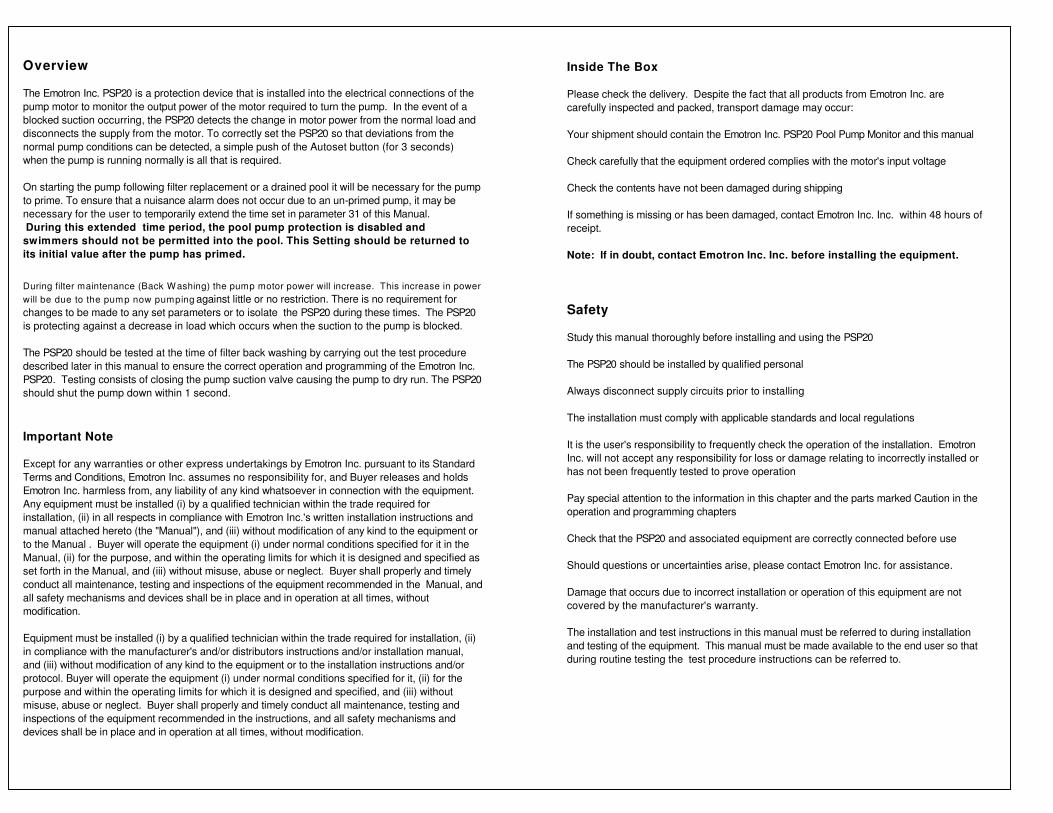
120Vac Single PhaseMotor InstallationInstallation
Pump
Pump
Line Line
Neutral
Ground
CT
Ground
Ground
Bolt
Neutral
1 2 3 4
Alarm Horn Connections
T1 T2 T3
120Vac
See Note 1
L1 L2 L3
Motor HPCurrent Transformer Secondary Windings
115 Vac
0.5 2
0.75 1
1.0 1
1.5 1
Motor HPCurrent Transformer Secondary Windings
115Vac
2.0 1
3.0 1
Model PSP 20-10- 25
Model PSP 20-10- 50
Note 1
Review Tables and pass the motor lead on phase
T1 through the center of the supplied Current
Transformer (CTM) the number of times shown
(Example below shows 2 windings)
Motor
T1
FOR 120V SINGLE PHASE
DO NOT REMOVE
PRE-INSTALLED LINK
L1 L2 L3
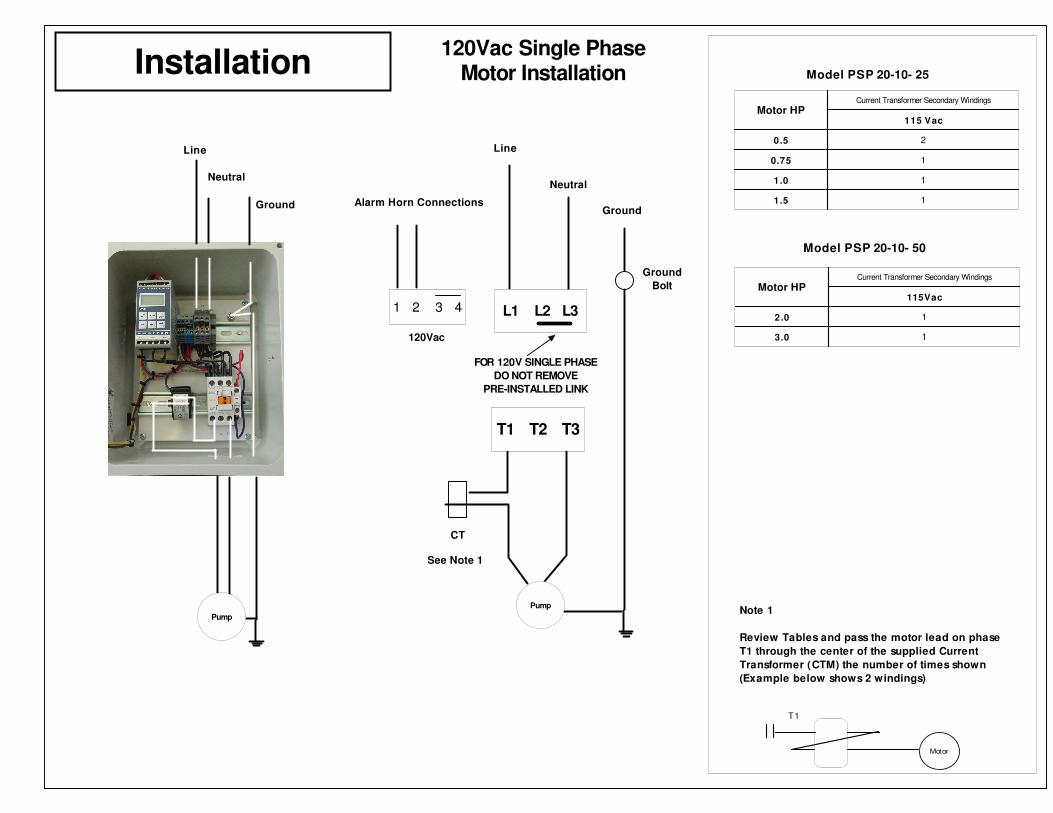
Installation
Pump
Pump
Line 1 Line 1
Line 2
Ground
CT
Ground
Ground
Bolt
Line 2
208/220Vac Single PhaseMotor Installation
INSTALL SUPPLIED LINK
HERE
Install Supplied Link
1 2 3 4
Alarm Horn Connections
208/220Vac
See Note 1
T1 T2 T3
Motor HPCurrent Transformer Secondary Windings
208/230 Vac
0.5 4
0.75 2
1.0 2
1.5 2
2.0 1
3.0 1
Motor HPCurrent Transformer Secondary Windings
208/230Vac
5.0 1
7.5 1
Note 1
Review Tables and pass the motor lead on phase
T1 through the center of the supplied Current
Transformer (CTM) the number of times shown
(Example below shows 2 windings)
Motor
T1
Model PSP 20-20- 25
Model PSP 20-20- 50
Motor HPCurrent Transformer Secondary Windings
208/230Vac
10.0 1
Model PSP 20-20- 65
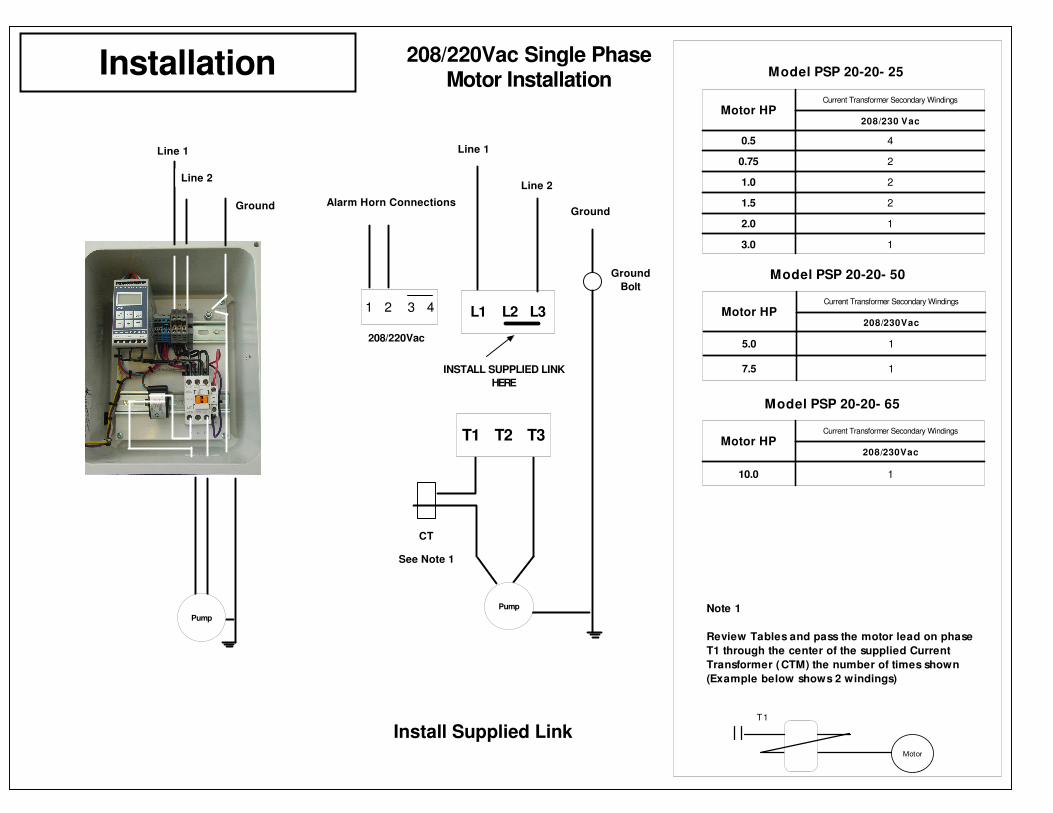
Installation
Pump
L1
L1L2
Ground
CT
Ground
Ground
Screw
L3
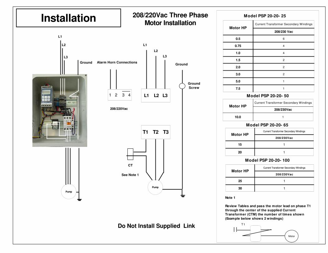
208/220Vac Three PhaseMotor Installation
Pump
L3
L2
Do Not Install Supplied Link
1 2 3 4
Alarm Horn Connections
208/220Vac
See Note 1
T1 T2 T3
L1 L2 L3
Model PSP 20-20- 25
Model PSP 20-20- 50
Motor HPCurrent Transformer Secondary Windings
208/230 Vac
0.5 6
0.75 4
1.0 4
1.5 2
2.0 2
3.0 2
5.0 1
7.5 1
Motor HPCurrent Transformer Secondary Windings
208/230Vac
10.0 1
Motor HPCurrent Transformer Secondary Windings
208/230Vac
15 1
20 1
Model PSP 20-20- 65
Note 1
Review Tables and pass the motor lead on phase T1
through the center of the supplied Current
Transformer (CTM) the number of times shown
(Example below shows 2 windings)
Motor
T1
Motor HPCurrent Transformer Secondary Windings
208/230Vac
25 1
30 1
Model PSP 20-20- 100
Installation
Pump
L1
L1
L2
Ground
CT
Ground
Ground
Screw
L3
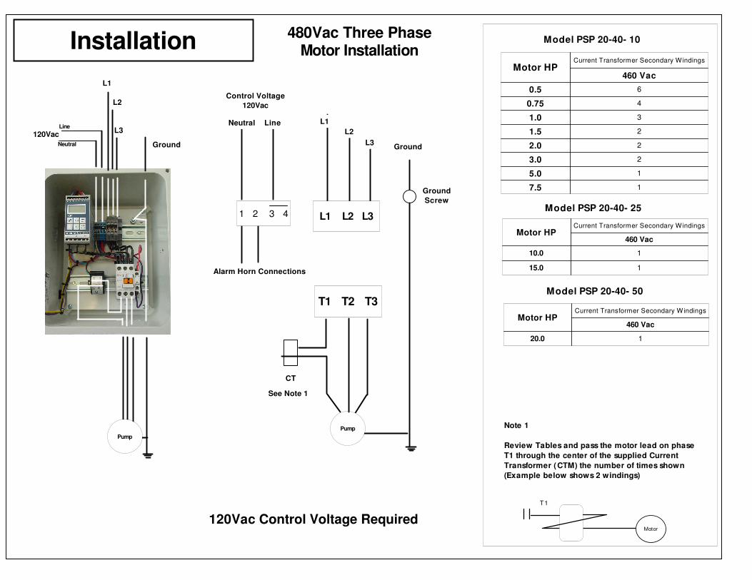
480Vac Three PhaseMotor Installation
Pump
L3 L2
1 2 3 4
LineNeutral
Control Voltage
120Vac
120Vac Control Voltage Required
See Note 1
T1 T2 T3
Alarm Horn Connections
Note 1
Review Tables and pass the motor lead on phase
T1 through the center of the supplied Current
Transformer (CTM) the number of times shown
(Example below shows 2 windings)
Motor
T1
Model PSP 20-40- 10
Motor HPCurrent Transformer Secondary Windings
460 Vac
0.5 6
0.75 4
1.0 3
1.5 2
2.0 2
3.0 2
5.0 1
7.5 1
Motor HPCurrent Transformer Secondary Windings
460 Vac
10.0 1
15.0 1
Model PSP 20-40- 25
Motor HPCurrent Transformer Secondary Windings
460 Vac
20.0 1
Model PSP 20-40- 50
L1 L2 L3
120Vac
Neutral
Line
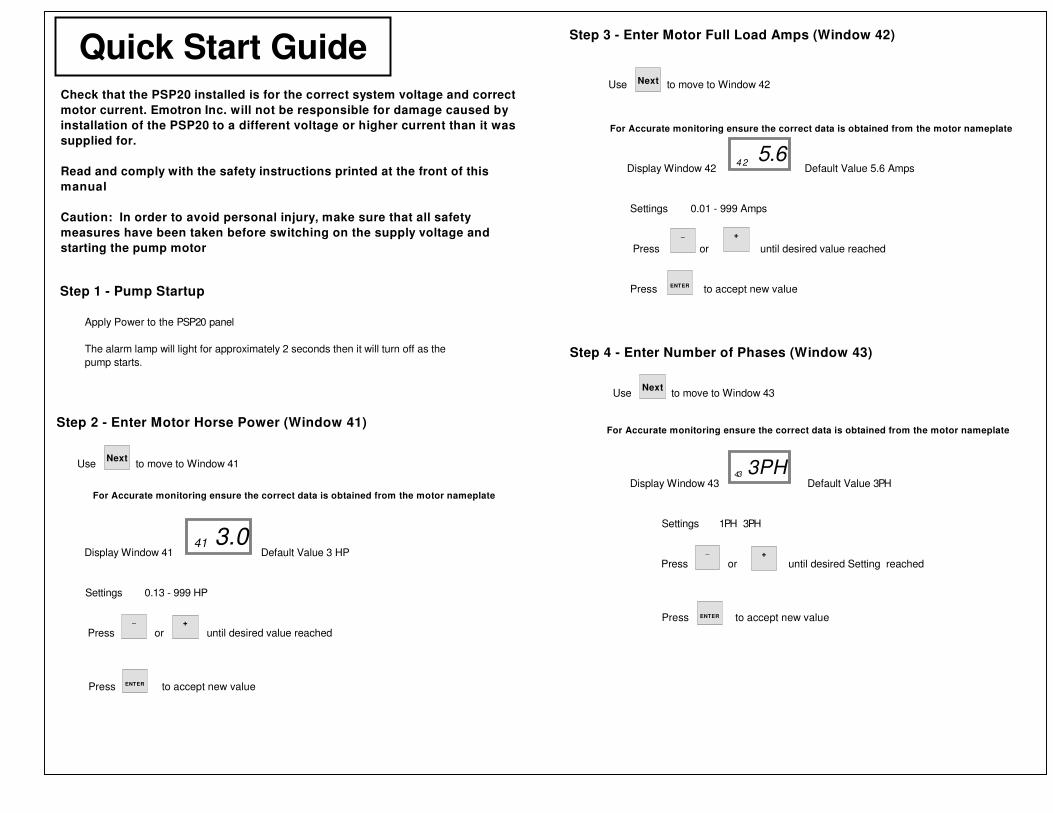
For Accurate monitoring ensure the correct data is obtained from the motor nameplate
Display Window 42 Default Value 5.6 Amps
Settings 0.01 - 999 Amps
Press or until desired value reached
Press to accept new value
5.642
_ +
For Accurate monitoring ensure the correct data is obtained from the motor nameplate
Display Window 43 Default Value 3PH
Settings 1PH 3PH
Press or until desired Setting reached
Press to accept new value
3PH43
_ +
ENTER
ENTER
Step 2 - Enter Motor Horse Power (Window 41)
For Accurate monitoring ensure the correct data is obtained from the motor nameplate
Display Window 41 Default Value 3 HP
Settings 0.13 - 999 HP
Press or until desired value reached
Press to accept new value
3.041
Quick Start Guide
Step 1 - Pump Startup
Use to move to Window 41Next
Step 3 - Enter Motor Full Load Amps (Window 42)
Use to move to Window 42Next
Step 4 - Enter Number of Phases (Window 43)
Use to move to Window 43Next
_ +
ENTER
Check that the PSP20 installed is for the correct system voltage and correct
motor current. Emotron Inc. will not be responsible for damage caused by
installation of the PSP20 to a different voltage or higher current than it was
supplied for.
Read and comply with the safety instructions printed at the front of this
manual
Caution: In order to avoid personal injury, make sure that all safety
measures have been taken before switching on the supply voltage and
starting the pump motor
Apply Power to the PSP20 panel
The alarm lamp will light for approximately 2 seconds then it will turn off as the
pump starts.
xx01
xx01
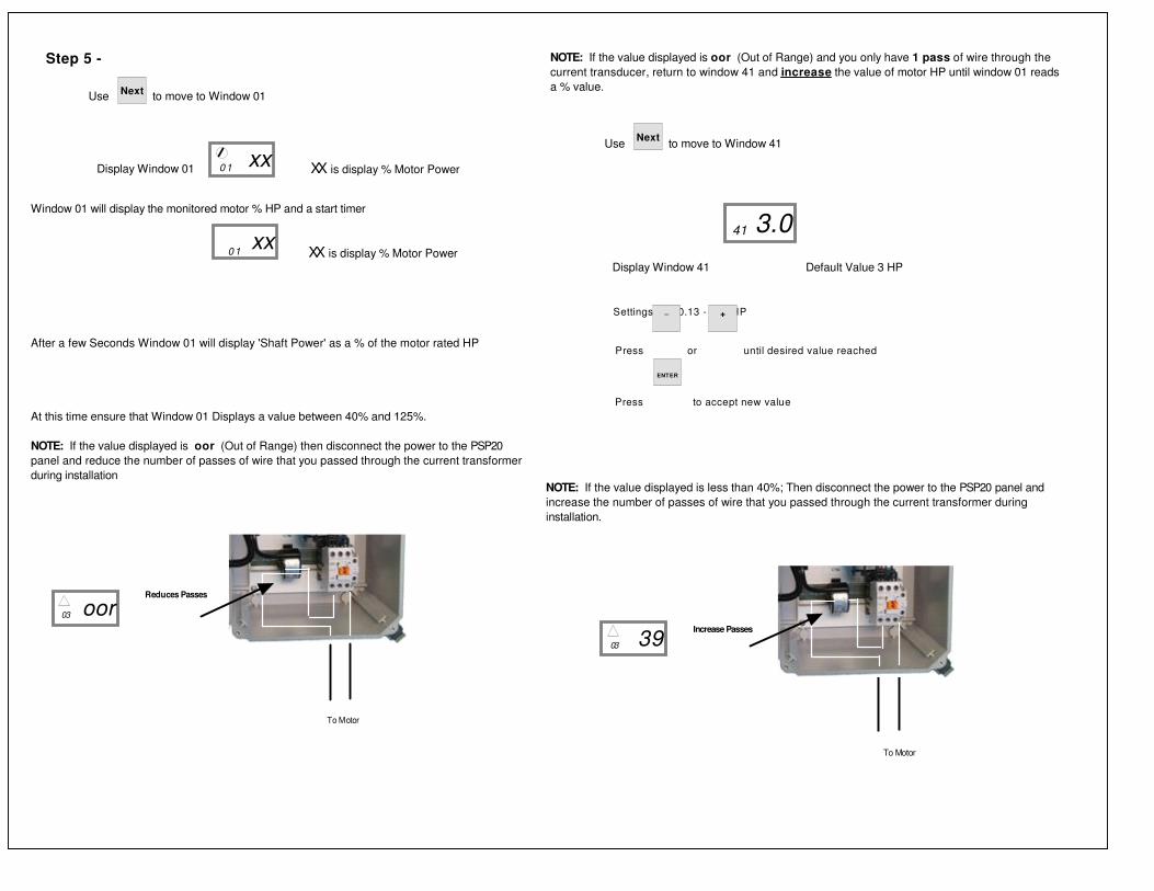
Step 5 -
Use to move to Window 01Next
Display Window 01
Window 01 will display the monitored motor % HP and a start timer
After a few Seconds Window 01 will display 'Shaft Power' as a % of the motor rated HP
At this time ensure that Window 01 Displays a value between 40% and 125%.
NOTE: If the value displayed is oor (Out of Range) then disconnect the power to the PSP20
panel and reduce the number of passes of wire that you passed through the current transformer
during installation
XX is display % Motor Power
XX is display % Motor Power
To Motor
See Installation Drawings for
Correct Number of times
Reduces Passes
3903
Increase Passes
NOTE: If the value displayed is less than 40%; Then disconnect the power to the PSP20 panel and
increase the number of passes of wire that you passed through the current transformer during
installation.
NOTE: If the value displayed is oor (Out of Range) and you only have 1 pass of wire through the
current transducer, return to window 41 and increase the value of motor HP until window 01 reads
a % value.
Display Window 41 Default Value 3 HP
Settings 0.13 - 999 HP
Press or until desired value reached
Press to accept new value
3.041
Use to move to Window 41Next
_ +
ENTER
See Installation Drawings for
Correct Number of times
To Motor
Reduces Passes
oor03
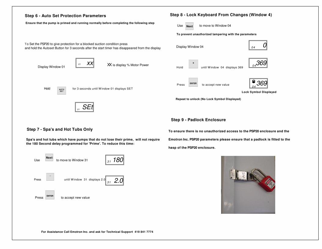
Step 9 - Padlock Enclosure
To ensure there is no unauthorized access to the PSP20 enclosure and the
Emotron Inc. PSP20 parameters please ensure that a padlock is fitted to the
hasp of the PSP20 enclosure.
To prevent unauthorized tampering with the parameters
Display Window 04
Hold until W indow 04 displays 369
Press to accept new value
Lock Symbol Displayed
Repeat to unlock (No Lock Symbol Displayed)
36904
004
+
ENTER 36904
Step 8 - Lock Keyboard From Changes (Window 4)
Use to move to Window 04Next
To Set the PSP20 to give protection for a blocked suction condition press
and hold the Autoset Button for 3 seconds after the start timer has disappeared from the display
Display Window 01
Hold for 3 seconds until W indow 01 displays SET
For Assistance Call Emotron Inc. and ask for Technical Support 419 841 7774
Step 7 - Spa's and Hot Tubs Only
Spa's and hot tubs which have pumps that do not lose their prime, will not require
the 180 Second delay programmed for 'Prime'. To reduce this time:
Press until W indow 31 displays 2.0
Press to accept new value
18031
ENTER
Use to move to Window 31Next
_
2.031
XX is display % Motor Power
AUT OSET
SEt01
xx01
Ensure that the pump is primed and running normally before completing the following step
Step 6 - Auto Set Protection Parameters
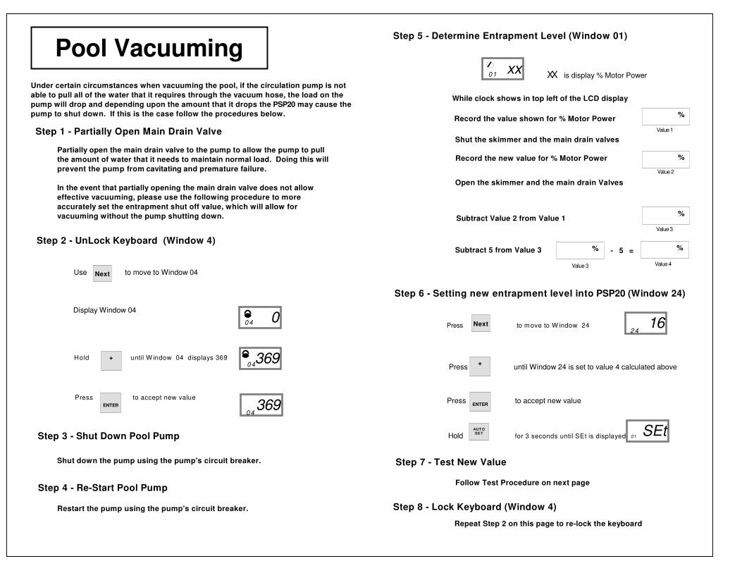
Under certain circumstances when vacuuming the pool, if the circulation pump is not
able to pull all of the water that it requires through the vacuum hose, the load on the
pump will drop and depending upon the amount that it drops the PSP20 may cause the
pump to shut down. If this is the case follow the procedures below.
Pool Vacuuming
Partially open the main drain valve to the pump to allow the pump to pull
the amount of water that it needs to maintain normal load. Doing this will
prevent the pump from cavitating and premature failure.
In the event that partially opening the main drain valve does not allow
effective vacuuming, please use the following procedure to more
accurately set the entrapment shut off value, which will allow for
vacuuming without the pump shutting down.
Step 2 - UnLock Keyboard (Window 4)
36904
004
+
ENTER 36904
Use to move to Window 04Next
Display Window 04
Hold until W indow 04 displays 369
Press to accept new value
Step 3 - Shut Down Pool Pump
Shut down the pump using the pump's circuit breaker.
Step 1 - Partially Open Main Drain Valve
Step 4 - Re-Start Pool Pump
Restart the pump using the pump's circuit breaker.
Step 5 - Determine Entrapment Level (Window 01)
xx01 XX is display % Motor Power
While clock shows in top left of the LCD display
Record the value shown for % Motor Power
Shut the skimmer and the main drain valves
%
Record the new value for % Motor Power %
Subtract Value 2 from Value 1 %
Step 6 - Setting new entrapment level into PSP20 (Window 24)
Value 1
Value 2
Value 3
Subtract 5 from Value 3 %
Value 3
- 5 = %
Value 4
Press to move to W indow 24
Press until Window 24 is set to value 4 calculated above
Press to accept new value
Hold for 3 seconds until SEt is displayed
Next 1624
+
ENTER
SEt01
AUT OSET
Open the skimmer and the main drain Valves
Step 7 - Test New Value
Follow Test Procedure on next page
Step 8 - Lock Keyboard (Window 4)
Repeat Step 2 on this page to re-lock the keyboard
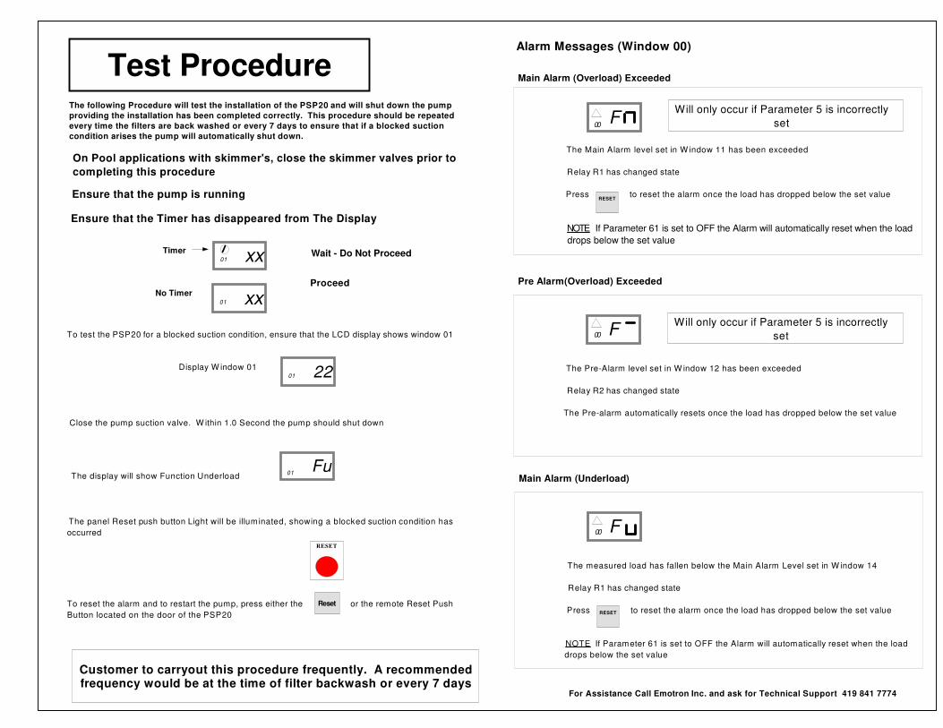
Alarm Messages (Window 00)
The Pre-Alarm level set in W indow 12 has been exceeded
Relay R2 has changed state
The Pre-alarm automatically resets once the load has dropped below the set value
00
Pre Alarm(Overload) Exceeded
F
The Main Alarm level set in W indow 11 has been exceeded
Relay R1 has changed state
Press to reset the alarm once the load has dropped below the set value
NOTE If Parameter 61 is set to OFF the Alarm will automatically reset when the load
drops below the set value
00
Main Alarm (Overload) Exceeded
F
RESET
The measured load has fallen below the Main Alarm Level set in W indow 14
Relay R1 has changed state
Press to reset the alarm once the load has dropped below the set value
NOTE If Parameter 61 is set to OFF the Alarm will automatically reset when the load
drops below the set value
00
Main Alarm (Underload)
F
RESET
Will only occur if Parameter 5 is incorrectly
set
Will only occur if Parameter 5 is incorrectly
set
For Assistance Call Emotron Inc. and ask for Technical Support 419 841 7774
The following Procedure will test the installation of the PSP20 and will shut down the pump
providing the installation has been completed correctly. This procedure should be repeated
every time the filters are back washed or every 7 days to ensure that if a blocked suction
condition arises the pump will automatically shut down.
Test Procedure
RESET
To test the PSP20 for a blocked suction condition, ensure that the LCD display shows window 01
Display W indow 01
Close the pump suction valve. W ithin 1.0 Second the pump should shut down
The display will show Function Underload
The panel Reset push button Light will be illuminated, showing a blocked suction condition has
occurred
To reset the alarm and to restart the pump, press either the or the remote Reset Push
Button located on the door of the PSP20
Fu01
2201
Customer to carryout this procedure frequently. A recommendedfrequency would be at the time of filter backwash or every 7 days
Reset
On Pool applications with skimmer's, close the skimmer valves prior to
completing this procedure
Ensure that the Timer has disappeared from The Display
xx01
Timer Wait - Do Not Proceed
Ensure that the pump is running
xx01
No Timer Proceed
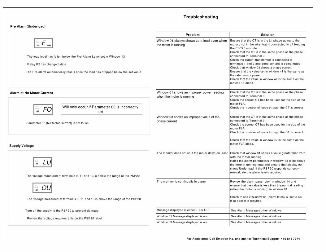
Troubleshooting
Problem Solution
Window 01 always shows zero load even when
the motor is running
Ensure that the CT is in the L1 phase going to the
motor , not in the wire that is connected to L1 feeding
the PSP20 module.
Check that the CT is in the same phase as the phase
connected to Terminal 9.
Check the current transformer is connected to
terminals 1 and 2 and good contact is being made.
Check that window 03 shows a phase current.
Ensure that the value set in window 41 is the same as
the rated motor power.
Check that the value in window 42 is the same as the
motor FLA amps.
Window 01 shows an improper power reading
when the motor is running
Check that the CT is in the same phase as the phase
connected to Terminal 9.
Check the correct CT has been used for the size of the
motor FLA.
Check the number of loops through the CT is correct
Window 03 shows an improper value of the
phase current
Check that the CT is in the same phase as the phase
connected to Terminal 9.
Check the correct CT has been used for the size of the
motor FLA.
Check the number of loops through the CT is correct
Check that the value in window 42 is the same as the
motor FLA amps.
The monitor does not shut the motor down on 'Test' Check that window 01 shows a value greater than zero
with the motor running.
Raise the alarm parameters in window 14 to be above
the normal running load and ensure that display 00
shows Underload. If the PSP20 responds correctly
re-evaluate the alarm levels required.
The monitor is continually in alarm Review the alarm parameter in window 14 and
ensure that the value is less than the normal reading
(when the motor is running) in window 01
Check to see if W indow 61 (alarm latch) is set to ON.
If so a reset is required.
Message displayed is either LU or OU See Alarm Messages other Windows
Window 01 Message displayed is oor See Alarm Messages other Windows
Window 03 Message displayed is oor See Alarm Messages other Windows
For Assistance Call Emotron Inc. and ask for Technical Support 419 841 7774
The load level has fallen below the Pre-Alarm Level set in W indow 13
Relay R2 has changed state
The Pre-alarm automatically resets once the load has dropped below the set value
00
Pre Alarm(Underload)
F
The voltage measured at terminals 9, 11 and 13 is below the range of the PSP20
The voltage measured at terminals 9, 11 and 13 is above the range of the PSP20
Turn off the supply to the PSP20 to prevent damage
Review the Voltage requirements on the PSP20 labe l
00
Supply Voltage
LU
00 OU
Parameter 62 (No Motor Current) is set to 'on'
00
Alarm at No Motor Current
FOWill only occur if Parameter 62 is incorrectly
set