psh series battery control module - cdn.automationdirect.com · rhino battery control module...
TRANSCRIPT

For the latest prices, please check AutomationDirect.com.
Safety Instructions• Read these instructions carefully and completely before
installation.
• These instructions cannot account for every possible condition of installation, operation or maintenance. The equipment must be installed and put into service by qualified personnel only.
• Before any installation, maintenance or modification work ensure that the main switch is switched off and prevented from being switched on again. Non-observance, touching of any live components or improper handling of this power supply can result in death, severe personal injury or substantial property damage. Proper and safe operation is dependent on proper storage, handling, installation and operation.
• Compliance with the relevant national and local regulations must be ensured. Before operation is started the following conditions must be ensured:
• When stranded wires are used, all strands must be fastened in the terminal blocks. (Potential danger of contact with the case.)
• Power supply and mains cables must be sufficiently fused.
• All output wires must be rated for the equipment output current and must be connected with the correct polarity.
• Sufficient cooling must be ensured.
• Never work on the equipment if power is supplied! Risk of electric arcs and electrical shock, which can cause death, severe personal injury or substantial property damage.
• Warning: Hazardous voltages and components storing a very substantial amount of energy are present in this power supply during normal operating conditions. However, these are inaccessible. Improper handling may result in an electric shock or serious burns!
• Do not open the equipment.
• Do not introduce any objects into the equipment.
• Adjustment potentiometer(s) may only be actuated using an insulated screwdriver.
• Keep away from fire and water.
RecyclingThe unit contains elements that are suitable for recycling, and components that need special disposal. You are therefore requested to make sure that the power supply will be recycled in an environmentally friendly manner at the end of its service life.
RHINO BatteRy CONtROl MOdule PSH-BCM360S
Features• Universal battery controller module for interruptible 24VDC
and 48VDC bus voltage• Redundant inputs for two independent sources• Battery protection for over voltage, deep discharge, short
circuit and reverse connection• Alarm outputs for input, output and battery condition• Remote On/Off for battery• Controlled end of charge voltage by optional temperature
sensor
General DescriptionThe PSH-BCM360S module provides a professional battery management system to charge and monitor an external 12V lead-acid battery with a capacity greater than 2.5 Ah. This module is a standalone unit and is designed to function with any 24VDC or 48VDC power supply output regulated to 1% or better. Together with one or a pair of 24VDC or 48VDC power supplies a perfect DC-UPS system can be configured.
The load voltage is configured through the means of a jumper on the unit with selectable 24VDC or 48VDC voltage levels. No other signals are required between the PSH-BCM360S and the connected power supplies for correct operation of the module.
The connected battery will be charged and held in charged mode by the power supply. In the event of a mains power failure the battery will supply output power without interruption.
A step up converter is used to maintain the selected output voltage level, Vnom − 6% (typical). To avoid overcharging the battery, an optional external temperature sensor can be used to adjust the battery voltage automatically to the required end-of-charge voltage. This can extend the battery life.
The battery is protected against deep discharge. Mains power and battery status are monitored regularly and failures indicated by corresponding LEDs and alarm outputs.
The module also offers the unique feature of redundant inputs as well as the battery backup. Redundancy is achieved by two internal decoupling diodes which allow operation with two independent voltage sources in order to increase the reliability of the output even further.
FOR TECHNICAL ASSISTANCE CALL 770-844-4200
229285C US
RHINO Battery Control Module PSH-BCM360S Operating Instructions 1st Edition, Rev. A 11/2018
Power Supplies tPWR-91w w w . a u t o m a t i o n d i r e c t . c o m / d c - p o w e r - s u p p l i e s
For the latest prices, please check AutomationDirect.com.
Mechanical InstallationThis equipment is designed for professional indoor systems. In operation the equipment must not be accessible.
The correct mounting position for optimal cooling performance must be observed. Mount the equipment upright on horizontal DIN rail. Do not cover any ventilation holes. Leave a free space of minimum 80mm [3.15 in] above and below the power supply and on each side of the power supply leave a minimum space of 25mm [0.98 in] which allows air convection. Observe power derating.
To attach the module to the DIN rail, hook top part of clip on the DIN rail, then push down and inward until you hear a clicking sound. To remove the device, pull the latch of the clip using an insulated flathead screwdriver. When the clip has cleared the bottom of the DIN rail remove the screwdriver from recess. Lift the device off the DIN rail.
Electrical InstallationOnly qualified personnel should carry out the installation. Following correct mounting of both the power supply and the BCM, the following steps must be followed to ensure correct connection and commissioning of the system.
1. Make sure the mains power is switched off, secured against switch on and not yet connected to the power supply.
2. Connect the power supply output to DC input of the BCM. 3. Ensure the blade fuse is correctly inserted into the BCM. 4. Configure the BCM module for your power supply voltage
by choosing the jumper position J6 (see Figure 1). 5. Exercising caution, the AC power wires should now be
connected to the power supply. Ensure that AC power is disabled by external isolation switch or circuit breaker.
6. When AC supply connection wires are connected and safe isolation is verified, AC power can now be switched on.
7. The potentiometer on the BCM is set by the factory to suit the recommended valve regulated lead acid battery from Panasonic and equivalent types and should not be adjusted by the user, unless lead acid batteries of different voltage temperature characteristics are connected. If a non recommended battery is used, the output voltage of the BCM module needs to be adjusted to the correct “End of Charge Voltage” obtained from battery manufacturer. Refer to the Battery Remote On/Off section to disconnect the battery, and set the required voltage using the potentiometer and a voltmeter.
8. If used, the temperature sensor should now be fixed to the battery and connected to the TS input on the BCM (Figure 2).
9. The battery wires should be connected on the BCM module; DO NOT connect to the battery first.
10. Then connect the battery wires on the battery. 11. For proper operation, a new system should always start up
with a fully charged battery. If a fully charged battery is not connected, the battery should be charged in full over night before any load is applied to the output of the BCM module.
12. To verify proper functionality, switch off the input AC power at the external circuit breaker and output power should be supplied from the battery if a fully charged battery has been connected.
13. The system is now fully operational and the output load can be connected.
OperationBattery Backup for UPS OperationThe PSH-BCM360S module extends any 24VDC or 48VDC power supply to perform as an uninterruptible DC power supply. This is achieved by connecting a 12V lead-acid battery to the BATT_IN connector of the unit. During normal operation, the connected power supply provides energy to load with a voltage level of Vin −0.5 V (typical, 0.5 V loss due to internal decoupling diodes) as well as charging the connected battery. If the connected supply fails, the battery is then connected to the load (battery power mode), a step up converter is used to maintain the selected output voltage level, Vnom − 6% (typical).
Dual Inputs for RedundancyThe module provides two inputs to connect two power supplies to facilitate a redundant system. If one of the two connected sources fails then the second supply will provide energy to load maintaining the desired operation of the unit. The unit is designed to work with any type of fully stabilized 24V or 48V power supply.
Output Voltage Level and EfficiencyThe PSH-BCM360S module functions with both 24VDC (15A) and 48VDC (7.5 A) supplies. The desired voltage is selectable by means of a jumper located on the side of the unit. It also offers very high efficiencies with up to 96% and 98% efficiency in normal mode for 24V and 48V modes respectively. In the battery power mode efficiencies are as high as 92% and 89% for 24V and 48V modes respectively.
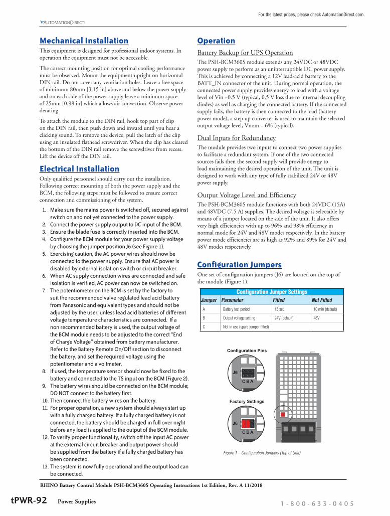
Configuration JumpersOne set of configuration jumpers (J6) are located on the top of the module (Figure 1).
Configuration Jumper SettingsJumper Parameter Fitted Not Fitted
A Battery test period 15 sec 10 min (default)
B Output voltage setting 24V (default) 48V
C Not in use (spare jumper fitted)
J6
C B A
Factory Settings
J6
C B A
Configuration Pins
Figure 1 – Configuration Jumpers (Top of Unit)
RHINO Battery Control Module PSH-BCM360S Operating Instructions 1st Edition, Rev. A 11/2018
Power Supplies 1 - 8 0 0 - 6 3 3 - 0 4 0 5tPWR-92

For the latest prices, please check AutomationDirect.com.
SignalsThe PSH-BCM360S module provides three signals to the user as an indication of the status of the unit; these signals are made available as LED indicators and corresponding isolated relay contacts (Figure 2) and are as follows.
Status SignalsSignal Description
DC-IN-OK The DC-IN-OK LED will illuminate and relay will close if at least one of the inputs is present and has a voltage within +20% / –3% tolerance.
BATT-OK
The BATT-OK LED will illuminate and relay will close if the battery is charged and has a low internal resistance. During battery discharge operation this signal monitors the output voltage and will switch off the LED and open the relay when the battery approaches the disconnection voltage.
DC-OUT-OK The DC-OUT-OK LED will illuminate and relay will close if the output voltage of the unit is higher than 85–90% of the nominal output voltage.
Note: All Signal Relay contacts are rated for 30VDC/1A, 60VDC/0.5 A.
Indicator LEDs – Status at a Glance
The BCM is operating normally.
Battery is supplying power to the load, and has sufficient charge.
Battery is supplying power to the load, but the battery voltage has dropped to near its threshold level.
NO power provided to the load. The battery is discharged below its operating threshold and no DC input power is present.
DC-IN-OK
BATT-OK
DC-OUT-OK
Temp. Sensor(TS)
Remote On/Off
DC-OUT-OK
BATT-OK
DC-IN OK
Temp. Sensor(TS)
Remote On/Off
DC-OUT-OK
BATT-OK
DC-IN OK
Battery Remote On/OffThe PSH-BCM360S module provides a Battery Remote On/Off input (2 pins on signal connector) intended to facilitate using the potentiometer to set a new battery charge voltage level.
Battery Remote On/Off InputBattery State Battery Remote On/Off Pins Voltage
Connected Open Circuit 5V
Disconnected Short Circuit <1V
If this input is short circuited (switch closed in Figure 3) the battery will be disconnected from the unit by means of an internal relay. A voltage of 1V or less across the Battery Remote On/Off terminals will disconnect the battery from the unit. If the Battery Remote On/Off signal is set to off (short between pins) this will not affect the output of the unit in normal mode, however the battery will be disconnected, hence it will not charge. If the unit enters battery power mode while the Battery Remote On/Off signal is off, the battery will remain disconnected, hence no energy will be supplied to the load.
Figure 2 – Signal Connector Pinout (Bottom of Unit)
Switch: 5V/5mA(min) to GND
+5V
10K
BatteryWhen the input DC voltage is present, the PSH-BCM360S unit will automatically charge the connected battery to a set end of battery charge voltage level, factory set for 25ºC for lead-acid batteries, using a constant current charging method of 1A (typical). As the battery voltage approaches the end of battery charge voltage level, the current will decrease proportionality; this characteristic is shown in Figure 4. If the battery specs differ from the 25ºC default setting and the temperature sensor is not used, the user can adjust the set end of battery charge voltage level by means of the “Battery Voltage Adjust” potentiometer.
1 2 3 4 5 6 7
Current
Voltage13.6V
1A
Time (hours)
Note: For Cycle Use (repeated charging and discharging of battery), we recommend a charge current of 0.4 CA or smaller (C = battery capacity), therefore batteries with a capacity of 2.5 Ah or less should not be used with this module.
Temperature SensorThe module also provides an input connector for an optional temperature compensation probe (part #PSM-TS). If this probe is connected, the unit will automatically compensate the end of battery charge voltage level depending on the measured temperature. The connection of the temperature probe also eliminates the need to change the potentiometer to compensate for a new temperature. The battery end voltage compensation curve is shown in Figure 5. (Applicable to factory setting of 13.6V/ 25ºC)
1313.213.413.613.8
1414.214.414.614.8
15
-15 -10 -5 0 5 10 15 20 25 30 35 40 45 50 [°C]
End of Charge Voltage
Battery End of Charge Voltage with Temperature Sensor[V]
Figure 3 – Simplified Battery Remote On/Off Circuitry
Figure 4 – Battery Charge Characteristics
Figure 5
RHINO Battery Control Module PSH-BCM360S Operating Instructions 1st Edition, Rev. A 11/2018
Power Supplies tPWR-93w w w . a u t o m a t i o n d i r e c t . c o m / d c - p o w e r - s u p p l i e s

For the latest prices, please check AutomationDirect.com.
Battery ProtectionThe PSH-BCM360S module protects the connected battery against short circuit and overload by the means of a built in 40A fuse. This fuse is a standard 40A blade type fuse, which is accessible from the front panel of the unit for ease of replacement should the fuse be damaged during operation. The module also prevents deep discharge of the battery by disconnecting the battery from the load once the voltage level of battery has dropped below a defined threshold. An early warning of this disconnection is given to the user by the BATT-OK signal. The BATT-OK signal will switch off when the battery voltage is roughly 1V above the deep discharge threshold.
Ambient temperature and power ratingThe PSH-BCM360S module operates at temperatures between −25°C and +70°C, with a minimum start-up temperature of −25°C. In normal mode the module can deliver full power up to 60°C. Refer to lead-acid battery spec sheet suggested operating temperature range and charge and discharge instructions below 0°C.
In Battery Power mode, a current derating of 2%/°C is required for 24V applications above 50°C. The boost current of 15A is available at ambient temperatures up to 40°C for a duration of 10 minutes as shown in Figure 6.
In Battery Power mode, a current derating of 2%/°C is required for 48V applications above 40°C. The boost current of 7.5 A is available at ambient temperatures up to 40°C for a duration of 3 minutes as shown in Figure 7.
456789
10111213141516
0 10 20 30 40 50 60
Out
put C
urre
nt [A
]
Ambient Temperature [°C]
Temperature Derating - Battery Power Mode 24V
NominalBoost
22.5
33.5
44.5
55.5
66.5
77.5
8
0 10 20 30 40 50 60
Out
put C
urre
nt [A
]
Ambient Temperature [°C]
Temperature Derating - Battery Power Mode 48V
NominalBoost
Figure 6
Figure 7
Technical SpecificationsTechnical Specifications
Input Specifications
Inputs 2 x 360W, for any single or two identical 24VDC or 48VDC sources
Input Voltage Range 24–28VDC or 48–56VDC (range selection with jumper)
Output (DC)Max. Output Power 360W
Output Voltage / Current
Normal Mode 24VDC mode: Vin − (0.4–0.8 V); 15A max. 48VDC mode: Vin − (0.4–0.7 V); 7.5 A max.
Battery Power Mode
24VDC mode: 22.2–22.9 V; 10A (15A in boost mode for 10 min) 48VDC mode: 44.6–45.3 V; 5A (7.5 A in boost mode for 3 min)
Efficiency (load >50% of Iout max.) Normal mode: 94–98% (battery charged) Battery power mode: 87–92%
General Specifications
Backup Battery 12V lead-acid battery with a capacity greater than 2.5 Ah (purchased separately)
Battery ProtectionAgainst over voltage, deep discharge, overcharge, short cir-cuit and reverse connection (built-in 40A user-replaceable blade fuse)
SignalsStatus DC OK input, DC OK output, BAT OK
all relay contact closed and LED on at status OK
Contact Rating 30VDC / 1.0 A max. 60VDC / 0.5 A max.
Battery Charging Current 0.8 – 1.2 A
Nominal Battery Voltage (at 25ºC) 13.6 VDC (factory setting)
Battery Voltage Adjustment Range 13.2 – 14.4 VDC
BCM Over-temperature Protection 100°C at back of BCM housing
Battery Resistance Test 100mOhm min. (normal mode at 25ºC)
Battery Test Current 2.5A / 60ms typ. (normal mode at 25ºC)
Battery Test Interval (Jumper Setting) 15s or 10min
Battery Warning 10.4 – 11.4 VDC (battery power mode only)
Battery Disconnection 9.1 – 9.7 VDC (battery power mode only)
Battery Remote Off disconnects battery, prevents battery power mode
Automatic Battery Temperature Compensation Range −15ºC to +50ºC [+5°F to +122°F]
Enclosure Material (Chassis/Cover) Aluminum / Stainless Steel
Weight 730g [25.8 oz]
Mounting DIN rail (EN 50022-35x15/7.5), snap-on self-locking spring
ConnectionsInput, Output, Battery Screw terminal (plug included)
Signal, Control Detachable screw terminals (plugs included)
Safety / Environmental
Operating Temperature
Normal Mode −25°C to +60°C [−13°F to +140°F] max. (without derating)
Battery Power Mode, Nominal
24VDC mode: derating above +50°C: 2.0 %/K 48VDC mode: derating above +40°C: 2.0 %/K
Battery Power Mode, Boost
24VDC mode: up to +40°C for 10 minutes max. 48VDC mode: up to +40°C for 3 minutes max.
Storage Temperature −25°C to +85°C [−13°F to +185°F] max.
Temperature Coefficient 0.02 %/K
Humidity 95% relative humidity max., non-condensing
Maximum Altitude 2000m
Safety Standards IEC/EN 60950-1, UL 60950-1 (2nd) + Am1:2011, UL508 requirements
MTBF (acc. to IEC 61709 at 25°C) > 1,500,000 hrs
Protection Class Class I
Degree of Protection IP20 (IEC/EN 60529)
Electromagnetic compatibility (EMC) Based on connected unit (no internal switching device)
Vibration Acc. IEC 60068-2-6 3 axis, 1 g sine sweep, 10–55 Hz, 1 oct/min
Shock Acc. IEC 60068-2-27 3 axis, 15 g half sine, 11ms
Safety ApprovalsCSA (tested to UL60950, UL508), File 229285CB test certificate IEC 60950-1 (SIQ for EN)
All specifications valid at nominal input voltage, full load and +25°C after warm-up time unless otherwise stated.
RHINO Battery Control Module PSH-BCM360S Operating Instructions 1st Edition, Rev. A 11/2018
Power Supplies 1 - 8 0 0 - 6 3 3 - 0 4 0 5tPWR-94

For the latest prices, please check AutomationDirect.com.
Electrical Connections and Wire SizeElectrical Connections and Wire Size
24V 48VInput & Output* 14–7 AWG
Max resistance 20mΩ17–7 AWG Max resistance 40mΩ
Battery Input 11–7 AWG; Max resistance 10mΩStatus and Control Signals 32–12 AWG
Tightening Torque Input, Output, Battery: 1.76 N·m Status and Control Signals: 0.19 N·m
Stripping Length 7.0 mm* Input cable (from power supply) and Output cable (to load) must be the same gauge wire.
Functional Diagram
Outline Dimensions
DCDC IN2
DC IN1+
+
–
–
POWER SUPPLY
24/48VLED
DC-IN-OK
INPUT
MONITOR
10K 5V
REMOTE BATTERY ON/OFF
PE
CHARGE
CONTROLLER
DISCHARGE
CONTROLLER
WCWCCW
Charge Current Settings
BATTERY
MONITOR
WCWCCW
POTBattery Voltage Adjustment
BATTERY12V
BATTERY RELAY
FUSE 40A
BATT-OK
LED
OUTPUT
MONITOR
DC-OUT-OK
LED
AC
DC
AC
DC
Output Voltage SettingVout 24V
Vout 48V
OUTPUT
24V/15A
48V/7.5A
+
–
+
–
AUTOMATIC TEMPERATURESENSOR DETECTION
NO TEMP. COMP.
TEMP. COMPENS.
TEMPERATURE SENSING
The correct mounting position for optimal cooling performance must be observed: Mount upright on horizontal DIN rail. Do not cover any ventilation holes. Leave a free space of minimum 80mm [3.15 in] above and below the power supply and on each side of the power supply a minimum space of 25mm [0.98 in] which allows air convection.
Units: mm [in]
RHINO Battery Control Module PSH-BCM360S Operating Instructions 1st Edition, Rev. A 11/2018
Power Supplies tPWR-95w w w . a u t o m a t i o n d i r e c t . c o m / d c - p o w e r - s u p p l i e s

For the latest prices, please check AutomationDirect.com.
RHINO Battery Control Modules Overview
Battery Control Module Selection GuidePart Number PSH-BCM360S PSB24-BCM960S PSL-24-BCM240 PSM24-BCM360S
Price $197.00 $58.00 $30.00 $161.00
Highlights Most versatileHighest power
Lowest cost/wattConformal coating
Lowest cost Legacy
Nominal Output Voltage 24/48 VDC 24 VDC 24 VDC 24 VDC
Amperage Rating 15A at 24 VDC, 7.5 A at 48 VDC 40A 10A 15A
Number of Power Inputs
Redundant inputs for two independent power supplies One power supply One power supply One power supply
Battery Type 12V sealed lead acid 24V sealed lead acid 24V sealed lead acid 24V sealed lead acid
Protection Type
Over voltage, Over current,
Deep discharge, Reverse polarity,
Battery overcharge, Over temperature
Battery Temperature Compensation Yes No No Yes
Compatibility Universal Universal Universal Requires RHINO PSM24 power supply
A battery control module (BCM), in combination with an external sealed lead acid battery, can be added to a DC power supply to create a DC uninterruptible power supply (UPS) that will maintain power to a connected load upon loss of mains power.
The battery control module performs several key functions in the DC UPS system. Under normal conditions, it monitors the status of the DC input power, monitors and controls charging of the external lead acid battery, and provides status/alarm contacts to allow remote monitoring of the state of the UPS.
In the event that the DC power supply voltage drops out, the BCM monitors and supplies power to the load from the battery and monitors the battery during discharge.
Several battery control modules, with a range of features, are available for use with RHINO power supplies. Key differentiating features of the battery control modules are delineated in the following table.
Power Supplies 1 - 8 0 0 - 6 3 3 - 0 4 0 5tPWR-90