pseudowire · cisco mwr 2941 mobile wireless edge router software configuration guide, release...
TRANSCRIPT
Cisco MWR 2941 Mobile Wireless Edge RouteOL-23889-01
C H A P T E R 22
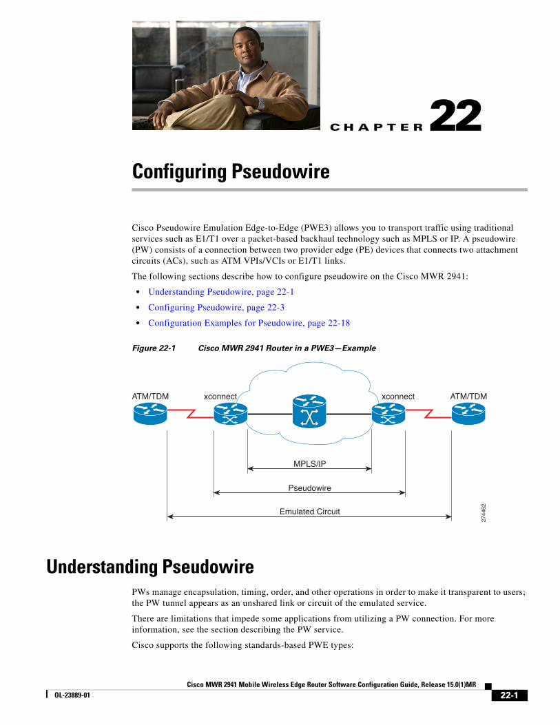
Configuring PseudowireCisco Pseudowire Emulation Edge-to-Edge (PWE3) allows you to transport traffic using traditional services such as E1/T1 over a packet-based backhaul technology such as MPLS or IP. A pseudowire (PW) consists of a connection between two provider edge (PE) devices that connects two attachment circuits (ACs), such as ATM VPIs/VCIs or E1/T1 links.
The following sections describe how to configure pseudowire on the Cisco MWR 2941:
• Understanding Pseudowire, page 22-1
• Configuring Pseudowire, page 22-3
• Configuration Examples for Pseudowire, page 22-18
Figure 22-1 Cisco MWR 2941 Router in a PWE3—Example
Understanding PseudowirePWs manage encapsulation, timing, order, and other operations in order to make it transparent to users; the PW tunnel appears as an unshared link or circuit of the emulated service.
There are limitations that impede some applications from utilizing a PW connection. For more information, see the section describing the PW service.
Cisco supports the following standards-based PWE types:
ATM/TDM ATM/TDMxconnectxconnect
MPLS/IP
Pseudowire
Emulated Circuit
2744
62
22-1r Software Configuration Guide, Release 15.0(1)MR
Chapter 22 Configuring Pseudowire Understanding Pseudowire
• Structure-Agnostic TDM over Packet, page 22-2
• Structure-Aware TDM Circuit Emulation Service over Packet-Switched Network, page 22-2
• Transportation of Service Using ATM over MPLS, page 22-2
• Transportation of Service Using Ethernet over MPLS, page 22-3
Structure-Agnostic TDM over PacketSAToP encapsulates TDM bit-streams (T1, E1, T3, E3) as PWs over PSNs. It disregards any structure that may be imposed on streams, in particular the structure imposed by the standard TDM framing.
The protocol used for emulation of these services does not depend on the method in which attachment circuits are delivered to the PEs. For example, a T1 attachment circuit is treated the same way for all delivery methods, including: PE on copper, multiplex in a T3 circuit, mapped into a virtual tributary of a SONET/SDH circuit, or carried over a network using unstructured Circuit Emulation Service (CES). Termination of specific carrier layers used between the PE and circuit emulation (CE) is performed by an appropriate network service provider (NSP).
For instructions on how to configure SAToP, see Configuring Structure-Agnostic TDM over Packet (SAToP). For a sample SAToP configuration, see Configuration Examples for Pseudowire.
Structure-Aware TDM Circuit Emulation Service over Packet-Switched Network
CESoPSN encapsulates structured (NxDS0) TDM signals as PWs over PSNs. It complements similar work for structure-agnostic emulation of TDM bit-streams, such as PWE3-SAToP.
Emulation of NxDS0 circuits saves PSN bandwidth and supports DS0-level grooming and distributed cross-connect applications. It also enhances resilience of CE devices due to the effects of loss of packets in the PSN.
CESoPSN supports channel-associated signaling (CAS) for E1 and T1 interfaces. CAS provides signaling information within each DS0 channel as opposed to using a separate signaling channel. CAS also referred to as in-band signaling or robbed bit signaling.
For instructions on how to configure SAToP, see Configuring Circuit Emulation Service over Packet-Switched Network (CESoPSN). For a sample SAToP configuration, see Configuration Examples for Pseudowire.
Transportation of Service Using ATM over MPLSAn Asynchronous Transfer Mode (ATM) over MPLS PW is used to carry ATM cells over an MPLS network. It is an evolutionary technology that allows you to migrate packet networks from legacy networks, yet provides transport for legacy applications. ATM over MPLS is particularly useful for transporting 3G voice traffic over MPLS networks.
You can configure ATM over MPLS in the following modes:
• N-to-1 Cell Mode—Maps one or more ATM virtual channel connections (VCCs) or virtual permanent connection (VPCs) to a single pseudowire.
• 1-to-1 Cell Mode—Maps a single ATM VCC or VPC to a single pseudowire.
• Port Mode—Map one physical port to a single pseudowire connection.
22-2Cisco MWR 2941 Mobile Wireless Edge Router Software Configuration Guide, Release 15.0(1)MR
OL-23889-01

Chapter 22 Configuring Pseudowire Configuring Pseudowire
The Cisco MWR 2941 also supports cell packing and PVC mapping for ATM over MPLS pseudowires.
Note Release 15.0(1)MR does not support ATM over MPLS N-to-1 Cell Mode or 1-to-1 Cell Mode.
For more information about how to configure ATM over MPLS, see Configuring Transportation of Service Using ATM over MPLS. For sample ATM over MPLS configurations, see Configuration Examples for Pseudowire.
Transportation of Service Using Ethernet over MPLSEthernet over MPLS (EoMPLS) PWs provide a tunneling mechanism for Ethernet traffic through an MPLS-enabled Layer 3 core network. EoMPLS PWs encapsulate Ethernet protocol data units (PDUs) inside MPLS packets and use label switching to forward them across an MPLS network. EoMPLS PWs are an evolutionary technology that allows you to migrate packet networks from legacy networks while providing transport for legacy applications. EoMPLS PWs also simplify provisioning, since the provider edge equipment only requires Layer 2 connectivity to the connected customer edge (CE) equipment. The Cisco MWR 2941 implementation of EoMPLS PWs is compliant with the RFC 4447 and 4448 standards.
For instructions on how to create an EoMPLS PW, see Configuring Transportation of Service Using Ethernet over MPLS.
Limitations
When configuring an EoMPLS pseudowire on the Cisco MWR 2941, you cannot configure an IP address on the same interface as the pseudowire.
Configuring PseudowireThis section describes how to configure pseudowire on the Cisco MWR 2941. The Cisco MWR 2941 supports pseudowire connections using SAToP, CESoPSN, and ATM over MPLS. The following sections describe how to configure pseudowire connections on the Cisco MWR 2941.
• Using Pseudowire Classes, page 22-4
• Using CEM Classes, page 22-5
• Configuring a Backup Peer, page 22-6
• Configuring Structure-Agnostic TDM over Packet (SAToP), page 22-7
• Configuring Circuit Emulation Service over Packet-Switched Network (CESoPSN), page 22-7
• Configuring Transportation of Service Using ATM over MPLS, page 22-10
• Configuring Transportation of Service Using Ethernet over MPLS, page 22-17
For full descriptions of each command, see the Cisco MWR 2941 Mobile Wireless Edge Router IOS Command Reference, Release 15.0(1)MR. For pseudowire configuration examples, see Configuration Examples for Pseudowire, page 22-18
22-3Cisco MWR 2941 Mobile Wireless Edge Router Software Configuration Guide, Release 15.0(1)MR
OL-23889-01

Chapter 22 Configuring Pseudowire Configuring Pseudowire
Using Pseudowire ClassesA pseudowire class allows you to create a single configuration template for multiple pseudowire connections. You can apply pseudowire classes to all pseudowire types. Follow these steps to configure a pseudowire class:
Note You cannot use the encapsulation mpls parameter with the pw-class parameter.
Note The use of the xconnect command can vary depending on the type of pseudowire you are configuring.
Command Purpose
Step 1 enable
Example:Router> enable
Enables privileged EXEC mode.
• Enter your password if prompted.
Step 2 configure terminal
Example:Router# configure terminal
Enters global configuration mode.
Step 3 Router(config)# pseudowire-class newclass
Creates a new pseudowire class.
Step 4 Router(config-pw-class)# encapsulation mpls
Sets an encapsulation type. For an ATM over MPLS pseudowire, use mpls. For a CESoPSN pseudowire using UDP encapsulation, use udp.
Step 5 Router(config-pw-class)# mpls experimental 5
Specifies the 3-bit EXP field in the MPLS label used for pseudowire packets.
Note For more information about the mpls experimental command, see the Cisco MWR 2941 Mobile Wireless Edge Router IOS Command Reference, Release 15.0(1)MR.
Step 6 Router(config-pw-class)# preferred-path peer 50.0.0.1
Specifies a preferred path if there are multiple paths that traffic can cross within the pseudowire class.
Note This command applies only to MPLS pseudowires.
Step 7 Router(config)# interface atm0/ima0Router(config-if)# pvc 0/40 l2transportRouter(cfg-if-atm-l2trans-pvc)# encapsulation aal0
Configures the pseudowire interface to use for the new pseudowire class. This example shows an ATM IMA interface.
Step 8 Router(cfg-if-atm-l2trans-pvc)# xconnect 1.1.1.1 40 pw-class myclass
Binds an attachment circuit to the ATM IMA interface to create an ATM pseudowire. Use the pw-class parameter to specify the pseudowire class that the ATM pseudowire interface uses.
Step 9 exit
Example:Router(config)# exit
Router#
Exits configuration mode.
22-4Cisco MWR 2941 Mobile Wireless Edge Router Software Configuration Guide, Release 15.0(1)MR
OL-23889-01

Chapter 22 Configuring Pseudowire Configuring Pseudowire
Using CEM Classes A CEM class allows you to create a single configuration template for multiple CEM pseudowires. Follow these steps to configure a CEM class:
Note You cannot apply a CEM class to other pseudowire types such as ATM over MPLS.
Command Purpose
Step 1 enable
Example:Router> enable
Enables privileged EXEC mode.
• Enter your password if prompted.
Step 2 configure terminal
Example:Router# configure terminal
Enters global configuration mode.
Step 3 Router(config)# class cem mycemclass
Creates a new CEM class
Step 4 Router(config-cem-class)# payload-size 512Router(config-cem-class)# dejitter-buffer 10Router(config-cem-class)# idle-pattern 0x55
Enter the configuration commands common to the CEM class. This example specifies a sample rate, payload size, dejitter buffer, and idle pattern.
Step 5 Router(config-cem-class)# exit Returns to the config prompt.
Step 6 Router(config)# interface cem 0/0Router(config-if)# no ip addressRouter(config-if)# cem 0Router(config-if-cem)# cem class mycemclassRouter(config-if-cem)# xconnect 10.10.10.10 200 encapsulation mpls
Configure the CEM interface that you want to use for the new CEM class.
Note The use of the xconnect command can vary depending on the type of pseudowire you are configuring.
Step 7 Router(config-if-cem)# exitRouter(config-if)#
Exits the CEM interface.
Step 8 exit
Example:Router(config)# exit
Router#
Exits configuration mode.
22-5Cisco MWR 2941 Mobile Wireless Edge Router Software Configuration Guide, Release 15.0(1)MR
OL-23889-01
Chapter 22 Configuring Pseudowire Configuring Pseudowire
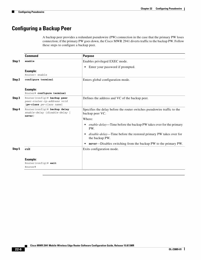
Configuring a Backup PeerA backup peer provides a redundant pseudowire (PW) connection in the case that the primary PW loses connection; if the primary PW goes down, the Cisco MWR 2941 diverts traffic to the backup PW. Follow these steps to configure a backup peer.
Command Purpose
Step 1 enable
Example:Router> enable
Enables privileged EXEC mode.
• Enter your password if prompted.
Step 2 configure terminal
Example:Router# configure terminal
Enters global configuration mode.
Step 3 Router(config)# backup peer peer-router-ip-address vcid [pw-class pw-class name]
Defines the address and VC of the backup peer.
Step 4 Router(config)# backup delay enable-delay {disable-delay | never}
Specifies the delay before the router switches pseudowire traffic to the backup peer VC.
Where:
• enable-delay—Time before the backup PW takes over for the primary PW.
• disable-delay—Time before the restored primary PW takes over for the backup PW.
• never—Disables switching from the backup PW to the primary PW.
Step 5 exit
Example:Router(config)# exit
Router#
Exits configuration mode.
22-6Cisco MWR 2941 Mobile Wireless Edge Router Software Configuration Guide, Release 15.0(1)MR
OL-23889-01
Chapter 22 Configuring Pseudowire Configuring Pseudowire
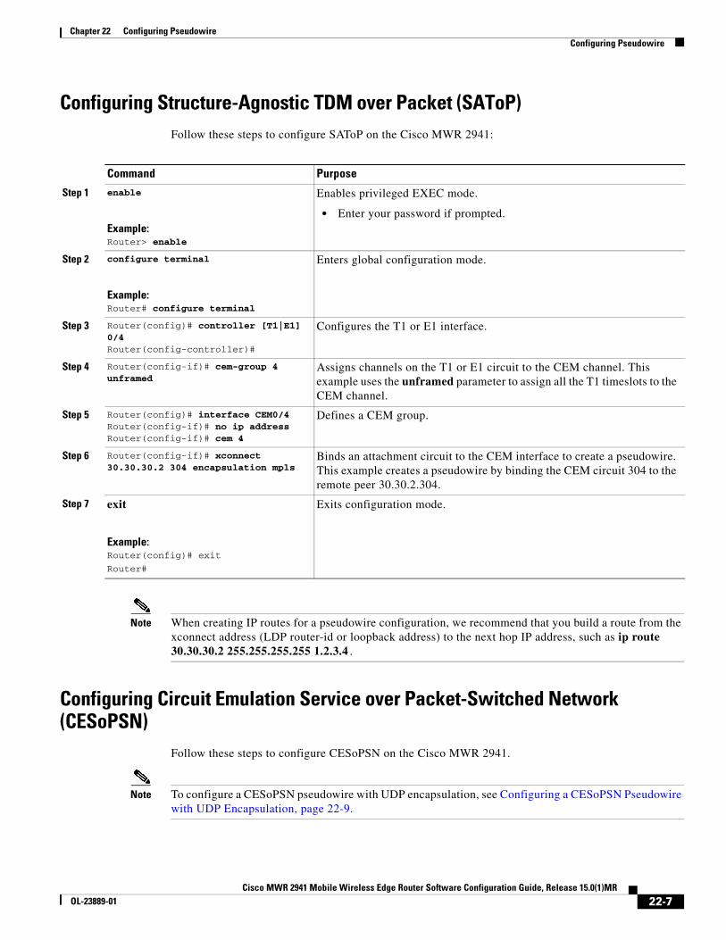
Configuring Structure-Agnostic TDM over Packet (SAToP)Follow these steps to configure SAToP on the Cisco MWR 2941:
Note When creating IP routes for a pseudowire configuration, we recommend that you build a route from the xconnect address (LDP router-id or loopback address) to the next hop IP address, such as ip route 30.30.30.2 255.255.255.255 1.2.3.4.
Configuring Circuit Emulation Service over Packet-Switched Network (CESoPSN)
Follow these steps to configure CESoPSN on the Cisco MWR 2941.
Note To configure a CESoPSN pseudowire with UDP encapsulation, see Configuring a CESoPSN Pseudowire with UDP Encapsulation, page 22-9.
Command Purpose
Step 1 enable
Example:Router> enable
Enables privileged EXEC mode.
• Enter your password if prompted.
Step 2 configure terminal
Example:Router# configure terminal
Enters global configuration mode.
Step 3 Router(config)# controller [T1|E1] 0/4Router(config-controller)#
Configures the T1 or E1 interface.
Step 4 Router(config-if)# cem-group 4 unframed
Assigns channels on the T1 or E1 circuit to the CEM channel. This example uses the unframed parameter to assign all the T1 timeslots to the CEM channel.
Step 5 Router(config)# interface CEM0/4Router(config-if)# no ip addressRouter(config-if)# cem 4
Defines a CEM group.
Step 6 Router(config-if)# xconnect 30.30.30.2 304 encapsulation mpls
Binds an attachment circuit to the CEM interface to create a pseudowire. This example creates a pseudowire by binding the CEM circuit 304 to the remote peer 30.30.2.304.
Step 7 exit
Example:Router(config)# exit
Router#
Exits configuration mode.
22-7Cisco MWR 2941 Mobile Wireless Edge Router Software Configuration Guide, Release 15.0(1)MR
OL-23889-01

Chapter 22 Configuring Pseudowire Configuring Pseudowire
Command Purpose
Step 1 enable
Example:Router> enable
Enables privileged EXEC mode.
• Enter your password if prompted.
Step 2 configure terminal
Example:Router# configure terminal
Enters global configuration mode.
Step 3 Router(config)# controller [e1|t1] 0/0Router(config-controller)#
Enters configuration mode for the E1 or T1 controller.
Step 4 Router(config-controller)# mode {atm | cas}
Sets the controller in asynchronous transfer mode (ATM) or channel-associated signaling (CAS) mode.
Step 5 Router(config-controller)# cem-group 5 timeslots 1-24
Assigns channels on the T1 or E1 circuit to the circuit emulation (CEM) channel. This example uses the timeslots parameter to assign specific timeslots to the CEM channel.
Step 6 Router(config-controller)# exitRouter(config)#
Exits controller configuration.
Step 7 Router(config)# interface CEM0/5Router(config-if-cem)# cem 5Router(config-if-cem)# signaling inband-cas
Defines a CEM channel.
Step 8 Router(config-if-cem)# xconnect 30.30.30.2 305 encapsulation mpls
Binds an attachment circuit to the CEM interface to create a pseudowire. This example creates a pseudowire by binding the CEM circuit 5 to the remote peer 30.30.30.2.
Note When creating IP routes for a pseudowire configuration, we recommend that you build a route from the xconnect address (LDP router-id or loopback address) to the next hop IP address, such as ip route 30.30.30.2 255.255.255.255 1.2.3.4.
Step 9 Router(config-if-cem)# exitRouter(config)#
Exits the CEM interface.
Step 10 exit
Example:Router(config)# exit
Router#
Exits configuration mode.
22-8Cisco MWR 2941 Mobile Wireless Edge Router Software Configuration Guide, Release 15.0(1)MR
OL-23889-01
Chapter 22 Configuring Pseudowire Configuring Pseudowire
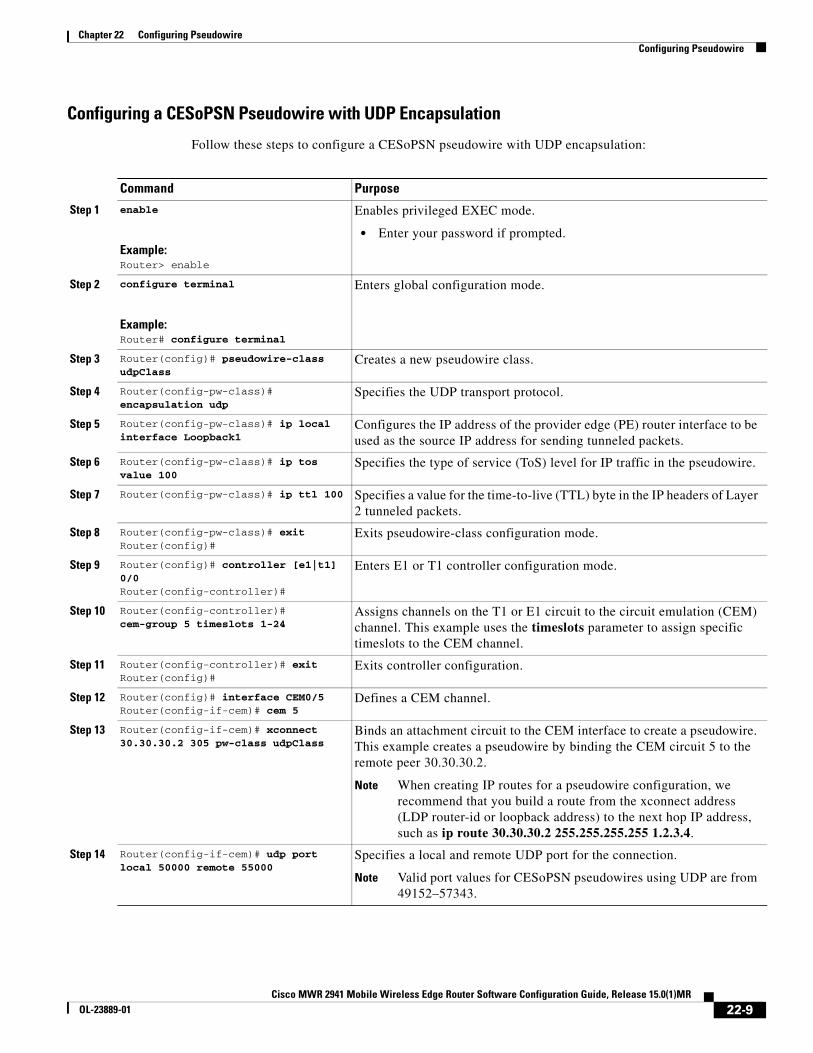
Configuring a CESoPSN Pseudowire with UDP Encapsulation
Follow these steps to configure a CESoPSN pseudowire with UDP encapsulation:
Command Purpose
Step 1 enable
Example:Router> enable
Enables privileged EXEC mode.
• Enter your password if prompted.
Step 2 configure terminal
Example:Router# configure terminal
Enters global configuration mode.
Step 3 Router(config)# pseudowire-class udpClass
Creates a new pseudowire class.
Step 4 Router(config-pw-class)# encapsulation udp
Specifies the UDP transport protocol.
Step 5 Router(config-pw-class)# ip local interface Loopback1
Configures the IP address of the provider edge (PE) router interface to be used as the source IP address for sending tunneled packets.
Step 6 Router(config-pw-class)# ip tos value 100
Specifies the type of service (ToS) level for IP traffic in the pseudowire.
Step 7 Router(config-pw-class)# ip ttl 100 Specifies a value for the time-to-live (TTL) byte in the IP headers of Layer 2 tunneled packets.
Step 8 Router(config-pw-class)# exitRouter(config)#
Exits pseudowire-class configuration mode.
Step 9 Router(config)# controller [e1|t1] 0/0Router(config-controller)#
Enters E1 or T1 controller configuration mode.
Step 10 Router(config-controller)# cem-group 5 timeslots 1-24
Assigns channels on the T1 or E1 circuit to the circuit emulation (CEM) channel. This example uses the timeslots parameter to assign specific timeslots to the CEM channel.
Step 11 Router(config-controller)# exitRouter(config)#
Exits controller configuration.
Step 12 Router(config)# interface CEM0/5Router(config-if-cem)# cem 5
Defines a CEM channel.
Step 13 Router(config-if-cem)# xconnect 30.30.30.2 305 pw-class udpClass
Binds an attachment circuit to the CEM interface to create a pseudowire. This example creates a pseudowire by binding the CEM circuit 5 to the remote peer 30.30.30.2.
Note When creating IP routes for a pseudowire configuration, we recommend that you build a route from the xconnect address (LDP router-id or loopback address) to the next hop IP address, such as ip route 30.30.30.2 255.255.255.255 1.2.3.4.
Step 14 Router(config-if-cem)# udp port local 50000 remote 55000
Specifies a local and remote UDP port for the connection.
Note Valid port values for CESoPSN pseudowires using UDP are from 49152–57343.
22-9Cisco MWR 2941 Mobile Wireless Edge Router Software Configuration Guide, Release 15.0(1)MR
OL-23889-01

Chapter 22 Configuring Pseudowire Configuring Pseudowire
Configuring Transportation of Service Using ATM over MPLSATM over MPLS pseudowires allow you to encapsulate and transport ATM traffic across an MPLS network. This service allows you to deliver ATM services over an existing MPLS network.
The following sections describe how to configure transportation of service using ATM over MPLS:
• Configuring the Controller
• Configuring an IMA Interface
• Configuring the ATM over MPLS Pseudowire Interface
Note For sample configurations for ATM over MPLS, see Configuration Examples for Pseudowire.
Configuring the Controller
Follow these steps to configure the controller.
Step 15 Router(config-if-cem)# exitRouter(config)#
Exits the CEM interface.
Step 16 exit
Example:Router(config)# exit
Router#
Exits configuration mode.
Command Purpose
Command Purpose
Step 1 enable
Example:Router> enable
Enables privileged EXEC mode.
• Enter your password if prompted.
Step 2 configure terminal
Example:Router# configure terminal
Enters global configuration mode.
Step 3 Router(config)# card type e1 0 0 Configures IMA on an E1 or T1 interface.
Step 4 Router(config)# controller E1 0/4Router(config-controller)#
Specifies the controller interface on which you want to enable IMA.
Step 5 Router(config-controller)# clock source internal
Sets the clock source to internal.
22-10Cisco MWR 2941 Mobile Wireless Edge Router Software Configuration Guide, Release 15.0(1)MR
OL-23889-01
Chapter 22 Configuring Pseudowire Configuring Pseudowire
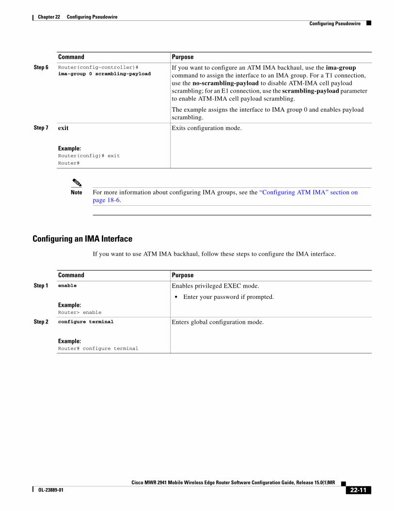
Note For more information about configuring IMA groups, see the “Configuring ATM IMA” section on page 18-6.
Configuring an IMA Interface
If you want to use ATM IMA backhaul, follow these steps to configure the IMA interface.
Step 6 Router(config-controller)# ima-group 0 scrambling-payload
If you want to configure an ATM IMA backhaul, use the ima-group command to assign the interface to an IMA group. For a T1 connection, use the no-scrambling-payload to disable ATM-IMA cell payload scrambling; for an E1 connection, use the scrambling-payload parameter to enable ATM-IMA cell payload scrambling.
The example assigns the interface to IMA group 0 and enables payload scrambling.
Step 7 exit
Example:Router(config)# exit
Router#
Exits configuration mode.
Command Purpose
Command Purpose
Step 1 enable
Example:Router> enable
Enables privileged EXEC mode.
• Enter your password if prompted.
Step 2 configure terminal
Example:Router# configure terminal
Enters global configuration mode.
22-11Cisco MWR 2941 Mobile Wireless Edge Router Software Configuration Guide, Release 15.0(1)MR
OL-23889-01

Chapter 22 Configuring Pseudowire Configuring Pseudowire
For more information about configuring IMA groups, see the “Configuring ATM IMA” section on page 18-6.
Configuring the ATM over MPLS Pseudowire Interface
You can configure ATM over MPLS is several modes according to the needs of your network. Use the appropriate section according to the needs of your network. You can configure the following ATM over MPLS pseudowire types:
• Configuring N-to-1 VCC Cell Transport Pseudowire—Maps multiple VCCs to a single pseudowire
• Configuring N-to-1 VPC Cell Transport—Maps multiple VPCs to a single pseudowire
• Configuring ATM AAL5 SDU VCC Transport—Maps a single ATM PVC to another ATM PVC
• Configuring a Port Mode Pseudowire—Maps one physical port to a single pseudowire connection
• Optional Configurations
Note Release 15.0(1)MR does not support N-to-1 VCC Cell Transport for mapping multiple PVCs, 1-to-1 VCC Cell Mode, or PVC mapping.
Step 3 Router(config-controller)# interface ATMslot/IMAgroup-number
Example:Router(config-controller)# interface atm0/ima0Router(config-if)#
Specifies the slot location and port of IMA interface group. The syntax is as follows:
• slot—The slot location of the ATM IMA port adapter.
• group-number—The group number of the IMA group.
The example specifies the slot number as 0 and the group number as 0.
Note To explicitly configure the IMA group ID for the IMA interface, you may use the optional ima group-id command. You cannot configure the same IMA group ID on two different IMA interfaces; therefore, if you configure an IMA group ID with the system-selected default ID already configured on an IMA interface, the system toggles the IMA interface to make the user-configured IMA group ID the effective IMA group ID. At the same, the system toggles the original IMA interface to select a different IMA group ID.
Step 4 Router(config-if)# no ip address Disables the IP address configuration for the physical layer interface.
Step 5 Router(config-if)# atm bandwidth dynamic
Specifies the ATM bandwidth as dynamic.
Step 6 Router(config-if)# no atm ilmi-keepalive
Disables the ILMI keepalive parameters.
Step 7 exit
Example:Router(config)# exit
Router#
Exits configuration mode.
Command Purpose
22-12Cisco MWR 2941 Mobile Wireless Edge Router Software Configuration Guide, Release 15.0(1)MR
OL-23889-01

Chapter 22 Configuring Pseudowire Configuring Pseudowire
Note When creating IP routes for a pseudowire configuration, build a route from the xconnect address (LDP router-id or loopback address) to the next hop IP address, such as ip route 30.30.30.2 255.255.255.255 1.2.3.4.
Configuring N-to-1 VCC Cell Transport Pseudowire
An N-to-1 VCC cell transport pseudowire maps one or more ATM virtual channel connections (VCCs) to a single pseudowire. Follow these steps to configure an N-to-1 pseudowire.
You can use the following methods to configure an N-to-1 VCC Cell Transport pseudowire.
Mapping a Single PVC to a Pseudowire
To map a single PVC to an ATM over MPLS pseudowire, apply the xconnect command at the PVC level. This configuration type only uses AAL0 encapsulation. Follow these steps to map a single PVC to an ATM over MPLS pseudowire.
Note Release 15.0(1)MR does not support mapping multiple VCCs to a pseudowire.
Command Purpose
Step 1 enable
Example:Router> enable
Enables privileged EXEC mode.
• Enter your password if prompted.
Step 2 configure terminal
Example:Router# configure terminal
Enters global configuration mode.
Step 3 Router(config)# interface atm0/ima0 Configures the ATM IMA interface.
Step 4 Router(config-if)# pvc 0/40 l2transportRouter(cfg-if-atm-l2trans-pvc)#
Defines a PVC. Use the l2transport keyword to configure the PVC as layer 2 virtual circuit.
Step 5 Router(cfg-if-atm-l2trans-pvc)# encapsulation aal0
Defines the encapsulation type for the PVC.
Step 6 Router(config-if)# xconnect 1.1.1.1 40 encapsulation mplsRouter(cfg-if-atm-l2trans-pvc-xconn)#
Binds an attachment circuit to the ATM IMA interface to create a pseudowire. This example creates a pseudowire by binding PVC 40 to the remote peer 1.1.1.1.
Step 7 Router(cfg-if-atm-l2trans-pvp-xconn)# endRouter#
Exits configuration mode.
22-13Cisco MWR 2941 Mobile Wireless Edge Router Software Configuration Guide, Release 15.0(1)MR
OL-23889-01
Chapter 22 Configuring Pseudowire Configuring Pseudowire
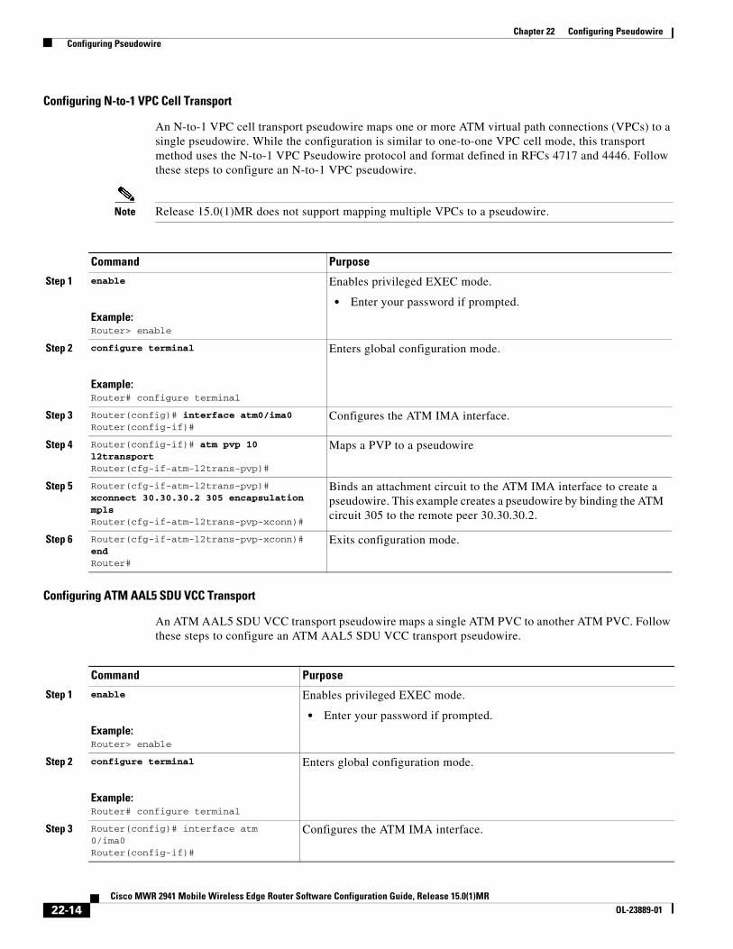
Configuring N-to-1 VPC Cell Transport
An N-to-1 VPC cell transport pseudowire maps one or more ATM virtual path connections (VPCs) to a single pseudowire. While the configuration is similar to one-to-one VPC cell mode, this transport method uses the N-to-1 VPC Pseudowire protocol and format defined in RFCs 4717 and 4446. Follow these steps to configure an N-to-1 VPC pseudowire.
Note Release 15.0(1)MR does not support mapping multiple VPCs to a pseudowire.
Configuring ATM AAL5 SDU VCC Transport
An ATM AAL5 SDU VCC transport pseudowire maps a single ATM PVC to another ATM PVC. Follow these steps to configure an ATM AAL5 SDU VCC transport pseudowire.
Command Purpose
Step 1 enable
Example:Router> enable
Enables privileged EXEC mode.
• Enter your password if prompted.
Step 2 configure terminal
Example:Router# configure terminal
Enters global configuration mode.
Step 3 Router(config)# interface atm0/ima0Router(config-if)#
Configures the ATM IMA interface.
Step 4 Router(config-if)# atm pvp 10 l2transportRouter(cfg-if-atm-l2trans-pvp)#
Maps a PVP to a pseudowire
Step 5 Router(cfg-if-atm-l2trans-pvp)# xconnect 30.30.30.2 305 encapsulation mplsRouter(cfg-if-atm-l2trans-pvp-xconn)#
Binds an attachment circuit to the ATM IMA interface to create a pseudowire. This example creates a pseudowire by binding the ATM circuit 305 to the remote peer 30.30.30.2.
Step 6 Router(cfg-if-atm-l2trans-pvp-xconn)# endRouter#
Exits configuration mode.
Command Purpose
Step 1 enable
Example:Router> enable
Enables privileged EXEC mode.
• Enter your password if prompted.
Step 2 configure terminal
Example:Router# configure terminal
Enters global configuration mode.
Step 3 Router(config)# interface atm 0/ima0Router(config-if)#
Configures the ATM IMA interface.
22-14Cisco MWR 2941 Mobile Wireless Edge Router Software Configuration Guide, Release 15.0(1)MR
OL-23889-01
Chapter 22 Configuring Pseudowire Configuring Pseudowire
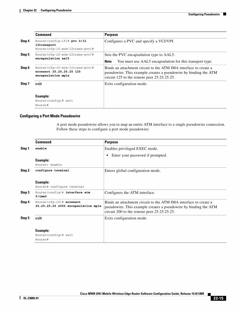
Configuring a Port Mode Pseudowire
A port mode pseudowire allows you to map an entire ATM interface to a single pseudowire connection. Follow these steps to configure a port mode pseudowire:
Step 4 Router(config-if)# pvc 0/12 l2transportRouter(cfg-if-atm-l2trans-pvc)#
Configures a PVC and specify a VCI/VPI.
Step 5 Router(cfg-if-atm-l2trans-pvc)# encapsulation aal5
Sets the PVC encapsulation type to AAL5.
Note You must use AAL5 encapsulation for this transport type.
Step 6 Router(cfg-if-atm-l2trans-pvc)# xconnect 25.25.25.25 125 encapsulation mpls
Binds an attachment circuit to the ATM IMA interface to create a pseudowire. This example creates a pseudowire by binding the ATM circuit 125 to the remote peer 25.25.25.25.
Step 7 exit
Example:Router(config)# exit
Router#
Exits configuration mode.
Command Purpose
Command Purpose
Step 1 enable
Example:Router> enable
Enables privileged EXEC mode.
• Enter your password if prompted.
Step 2 configure terminal
Example:Router# configure terminal
Enters global configuration mode.
Step 3 Router(config)# interface atm 0/ima0
Configures the ATM interface.
Step 4 Router(cfg-if)# xconnect 25.25.25.25 2000 encapsulation mpls
Binds an attachment circuit to the ATM IMA interface to create a pseudowire. This example creates a pseudowire by binding the ATM circuit 200 to the remote peer 25.25.25.25.
Step 5 exit
Example:Router(config)# exit
Router#
Exits configuration mode.
22-15Cisco MWR 2941 Mobile Wireless Edge Router Software Configuration Guide, Release 15.0(1)MR
OL-23889-01
Chapter 22 Configuring Pseudowire Configuring Pseudowire
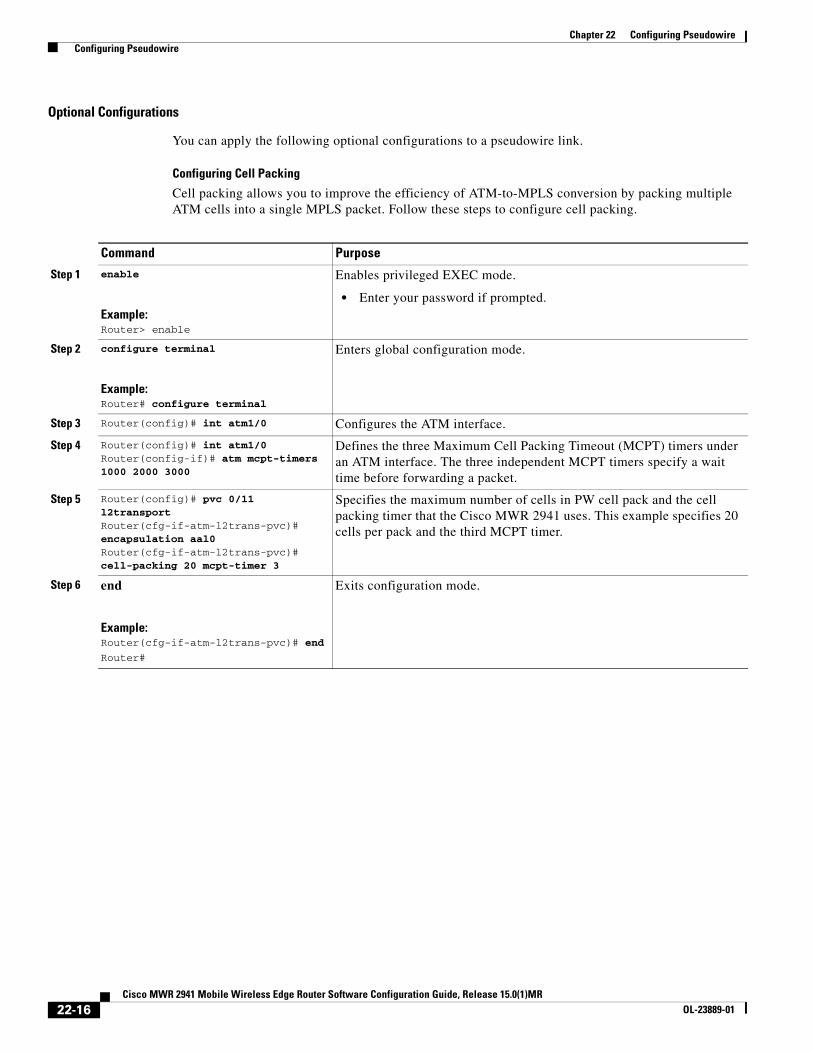
Optional Configurations
You can apply the following optional configurations to a pseudowire link.
Configuring Cell Packing
Cell packing allows you to improve the efficiency of ATM-to-MPLS conversion by packing multiple ATM cells into a single MPLS packet. Follow these steps to configure cell packing.
Command Purpose
Step 1 enable
Example:Router> enable
Enables privileged EXEC mode.
• Enter your password if prompted.
Step 2 configure terminal
Example:Router# configure terminal
Enters global configuration mode.
Step 3 Router(config)# int atm1/0 Configures the ATM interface.
Step 4 Router(config)# int atm1/0Router(config-if)# atm mcpt-timers 1000 2000 3000
Defines the three Maximum Cell Packing Timeout (MCPT) timers under an ATM interface. The three independent MCPT timers specify a wait time before forwarding a packet.
Step 5 Router(config)# pvc 0/11 l2transportRouter(cfg-if-atm-l2trans-pvc)# encapsulation aal0Router(cfg-if-atm-l2trans-pvc)# cell-packing 20 mcpt-timer 3
Specifies the maximum number of cells in PW cell pack and the cell packing timer that the Cisco MWR 2941 uses. This example specifies 20 cells per pack and the third MCPT timer.
Step 6 end
Example:Router(cfg-if-atm-l2trans-pvc)# end
Router#
Exits configuration mode.
22-16Cisco MWR 2941 Mobile Wireless Edge Router Software Configuration Guide, Release 15.0(1)MR
OL-23889-01

Chapter 22 Configuring Pseudowire Configuring Pseudowire
Configuring Transportation of Service Using Ethernet over MPLSEthernet over MPLS PWs allow you to transport Ethernet traffic over an existing MPLS network. For an overview of Ethernet over MPLS pseudowires, see Transportation of Service Using Ethernet over MPLS, page 22-3.
Configuring VLAN Mode
An Ethernet over MPLS pseudowire in VLAN mode creates a connection based on an existing VLAN ID on the Cisco MWR 2941. Follow these steps to configure an Ethernet over MPLS pseudowire in VLAN mode.
Note The Cisco MWR 2941 supports VLAN rewriting on EoMPLS PWs. If the two networks use different VLAN IDs, the router rewrites PW packets using the appropriate VLAN number for the local network.
Command Purpose
Step 1 enable
Example:Router> enable
Enables privileged EXEC mode.
• Enter your password if prompted.
Step 2 configure terminal
Example:Router# configure terminal
Enters global configuration mode.
Step 3 Router(config)# interface vlan 100 Creates the VLAN interface to bind to a pseudowire.
Step 4 Router(config-if)# xconnect 1.1.1.2 101 encapsulation mpls
Binds the Ethernet port interface to an attachment circuit to create a pseudowire. This example uses virtual circuit (VC) 101 to uniquely identify the PW. Ensure that the remote VLAN is configured with the same VC.
Note When creating IP routes for a pseudowire configuration, we recommend that you build a route from the xconnect address (LDP router-id or loopback address) to the next hop IP address, such as ip route 30.30.30.2 255.255.255.255 1.2.3.4.
Step 5 Router(config-if)# interface GigabitEthernet 0/1Router(config-if)# switchport trunk allowed vlan 100Router(config-if)# switchport mode trunk
Adds the GigabitEthernet interface to the VLAN.
Step 6 Creates a corresponding configuration on the remote router with the same VCID value. This configuration uses VCID 101.
Step 7 exit
Example:Router(config)# exit
Router#
Exits configuration mode.
22-17Cisco MWR 2941 Mobile Wireless Edge Router Software Configuration Guide, Release 15.0(1)MR
OL-23889-01

Chapter 22 Configuring Pseudowire Configuration Examples for Pseudowire
Note For more information about configuring VLANs on the Cisco MWR 2941, see the “Configuring VLANs” section on page 7-1.
Configuration Examples for PseudowireThe following sections contain full configuration examples for pseudowire connections.
• Asymmetric PWE3 Configuration, page 22-18
• PWE3 Redundancy Configuration, page 22-26
• TDM over MPLS Configuration, page 22-30
• ATM over MPLS Configuration, page 22-34
• Ethernet over MPLS Configuration, page 22-39
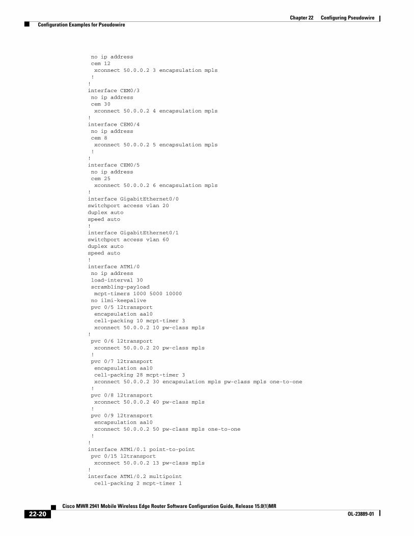
Asymmetric PWE3 ConfigurationThe following example shows an Asymmetric PWE3 configuration (Figure 22-2).
Figure 22-2 Asymmetric PWE3 Configuration
MWR_1version 12.4service timestamps debug datetime msec localtimeservice timestamps log datetime msec localtime
!hostname MWR1!boot-start-markerboot-end-marker!card type e1 0 0card type e1 0 1!!ip cef!!controller E1 0/0 clock source internal cem-group 1 unframed
GE0/0 (Uplink)
GE0/1 (Downlink)
MWR_1BTS/Node B BSC/RNCMWR_2
ATM
TDM
ATM
TDM
2530
34
22-18Cisco MWR 2941 Mobile Wireless Edge Router Software Configuration Guide, Release 15.0(1)MR
OL-23889-01

Chapter 22 Configuring Pseudowire Configuration Examples for Pseudowire
!controller E1 0/1 clock source internal cem-group 20 unframed!controller E1 0/2 clock source internal cem-group 12 unframed!controller E1 0/3 clock source internal cem-group 30 unframed!controller E1 0/4 clock source internal cem-group 8 unframed!controller E1 0/5 clock source internal cem-group 25 unframed!controller E1 1/0 mode atm clock source internal!controller E1 1/1 mode atm clock source internal!controller E1 1/2 mode atm clock source internal!controller E1 1/3!!pseudowire-class mpls encapsulation mpls preferred-path peer 50.0.0.2 !!interface Loopback50 ip address 50.0.0.1 255.255.255.255!interface CEM0/0 no ip address cem 1 xconnect 50.0.0.2 1 encapsulation mpls !!interface Vlan 20 ip address 20.0.0.1 255.0.0.0 mpls ip!interface CEM0/1 no ip address cem 20 xconnect 50.0.0.2 2 encapsulation mpls!interface Vlan 60 ip address 60.0.0.1 255.0.0.0 mpls ip!interface CEM0/2
22-19Cisco MWR 2941 Mobile Wireless Edge Router Software Configuration Guide, Release 15.0(1)MR
OL-23889-01
Chapter 22 Configuring Pseudowire Configuration Examples for Pseudowire
no ip address cem 12 xconnect 50.0.0.2 3 encapsulation mpls !!interface CEM0/3 no ip address cem 30 xconnect 50.0.0.2 4 encapsulation mpls!interface CEM0/4 no ip address cem 8 xconnect 50.0.0.2 5 encapsulation mpls !!interface CEM0/5 no ip address cem 25 xconnect 50.0.0.2 6 encapsulation mpls!interface GigabitEthernet0/0switchport access vlan 20duplex autospeed auto!interface GigabitEthernet0/1switchport access vlan 60duplex autospeed auto!interface ATM1/0 no ip address load-interval 30 scrambling-payload mcpt-timers 1000 5000 10000 no ilmi-keepalive pvc 0/5 l2transport encapsulation aal0 cell-packing 10 mcpt-timer 3 xconnect 50.0.0.2 10 pw-class mpls! pvc 0/6 l2transport xconnect 50.0.0.2 20 pw-class mpls ! pvc 0/7 l2transport encapsulation aal0 cell-packing 28 mcpt-timer 3 xconnect 50.0.0.2 30 encapsulation mpls pw-class mpls one-to-one ! pvc 0/8 l2transport xconnect 50.0.0.2 40 pw-class mpls ! pvc 0/9 l2transport encapsulation aal0 xconnect 50.0.0.2 50 pw-class mpls one-to-one !!interface ATM1/0.1 point-to-point pvc 0/15 l2transport xconnect 50.0.0.2 13 pw-class mpls!interface ATM1/0.2 multipoint cell-packing 2 mcpt-timer 1
22-20Cisco MWR 2941 Mobile Wireless Edge Router Software Configuration Guide, Release 15.0(1)MR
OL-23889-01

Chapter 22 Configuring Pseudowire Configuration Examples for Pseudowire
xconnect 50.0.0.2 12 encapsulation mpls pvc 0/10 l2transport encapsulation aal0 ! pvc 0/11 l2transport encapsulation aal0 ! pvc 0/12 l2transport encapsulation aal0 ! pvc 0/13 l2transport encapsulation aal0 !!interface ATM1/0.3 point-to-point pvc 0/16 l2transport encapsulation aal0 xconnect 50.0.0.2 14 encapsulation mpls !!interface ATM1/0.4 point-to-point pvc 0/17 l2transport encapsulation aal0 xconnect 50.0.0.2 15 pw-class mpls one-to-one !!interface ATM1/0.6 multipoint pvc 0/26 l2transport xconnect 50.0.0.2 16 pw-class mpls ! pvc 0/27 l2transport encapsulation aal0 cell-packing 8 mcpt-timer 3 xconnect 50.0.0.2 17 pw-class mpls ! pvc 0/28 l2transport encapsulation aal0 cell-packing 16 mcpt-timer 2 xconnect 50.0.0.2 18 pw-class mpls !!interface ATM1/0.7 multipoint!interface ATM1/1 no ip address scrambling-payload mcpt-timers 1000 5000 10000 no ilmi-keepalive cell-packing 20 mcpt-timer 2 xconnect 50.0.0.2 11 encapsulation mpls pvc 0/21 l2transport encapsulation aal0 ! pvc 0/22 l2transport encapsulation aal0 ! pvc 0/23 l2transport encapsulation aal0 !!interface ATM1/1.1 point-to-point!interface ATM1/1.2 multipoint!
22-21Cisco MWR 2941 Mobile Wireless Edge Router Software Configuration Guide, Release 15.0(1)MR
OL-23889-01

Chapter 22 Configuring Pseudowire Configuration Examples for Pseudowire
interface ATM1/2 no ip address scrambling-payload ima-group 0 no ilmi-keepalive!ip route 50.0.0.2 255.255.255.255 20.0.0.2!ip http serverno ip http secure-server!!mpls ldp router-id Loopback50 force!!line con 0 exec-timeout 0 0line aux 0line vty 0 4 login!network-clock-select 1 BITS!end
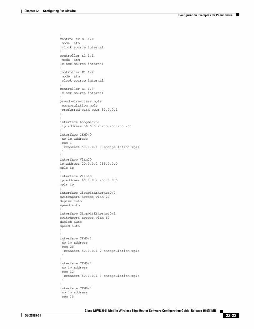
MWR_2version 12.4service timestamps debug datetime msecservice timestamps log datetime msec!hostname MWR2!boot-start-markerboot-end-marker!card type e1 0 0card type e1 0 1!enable password mypassword!no aaa new-model!ip cef!!controller E1 0/0 cem-group 1 unframed!controller E1 0/1 cem-group 20 unframed!controller E1 0/2 cem-group 12 unframed!controller E1 0/3 cem-group 30 unframed!controller E1 0/4 cem-group 8 unframed!controller E1 0/5 cem-group 25 unframed
22-22Cisco MWR 2941 Mobile Wireless Edge Router Software Configuration Guide, Release 15.0(1)MR
OL-23889-01
Chapter 22 Configuring Pseudowire Configuration Examples for Pseudowire
!controller E1 1/0 mode atm clock source internal!controller E1 1/1 mode atm clock source internal!controller E1 1/2 mode atm clock source internal!controller E1 1/3 clock source internal!pseudowire-class mpls encapsulation mpls preferred-path peer 50.0.0.1!!interface Loopback50 ip address 50.0.0.2 255.255.255.255!interface CEM0/0 no ip address cem 1 xconnect 50.0.0.1 1 encapsulation mpls !!interface Vlan20ip address 20.0.0.2 255.0.0.0mpls ip!interface Vlan60ip address 60.0.0.2 255.0.0.0mpls ip!interface GigabitEthernet0/0switchport access vlan 20duplex autospeed auto!interface GigabitEthernet0/1switchport access vlan 60duplex autospeed auto!!interface CEM0/1 no ip address cem 20 xconnect 50.0.0.1 2 encapsulation mpls !!interface CEM0/2 no ip address cem 12 xconnect 50.0.0.1 3 encapsulation mpls !!interface CEM0/3 no ip address cem 30
22-23Cisco MWR 2941 Mobile Wireless Edge Router Software Configuration Guide, Release 15.0(1)MR
OL-23889-01

Chapter 22 Configuring Pseudowire Configuration Examples for Pseudowire
xconnect 50.0.0.1 4 encapsulation mpls !!interface CEM0/4 no ip address cem 8 xconnect 50.0.0.1 5 encapsulation mpls !!interface CEM0/5 no ip address cem 25 xconnect 50.0.0.1 6 encapsulation mpls !!interface ATM1/0 ip address 1.1.1.2 255.0.0.0 load-interval 30 scrambling-payload mcpt-timers 1000 5000 10000 no ilmi-keepalive pvc 0/5 l2transport encapsulation aal0 cell-packing 25 mcpt-timer 3 xconnect 50.0.0.1 10 pw-class mpls ! pvc 0/6 l2transport xconnect 50.0.0.1 20 pw-class mpls ! pvc 0/7 l2transport encapsulation aal0 cell-packing 12 mcpt-timer 2 xconnect 50.0.0.1 30 encapsulation mpls pw-class mpls one-to-one ! pvc 0/8 l2transport xconnect 50.0.0.1 40 pw-class mpls ! pvc 0/9 l2transport encapsulation aal0 xconnect 50.0.0.1 50 pw-class mpls one-to-one ! pvc 0/99 protocol ip 1.1.1.1 broadcast encapsulation aal5snap !!interface ATM1/0.1 point-to-point pvc 0/15 l2transport xconnect 50.0.0.1 13 pw-class mpls !!interface ATM1/0.2 multipoint cell-packing 10 mcpt-timer 2 xconnect 50.0.0.1 12 encapsulation mpls pvc 0/10 l2transport encapsulation aal0 ! pvc 0/11 l2transport encapsulation aal0 ! pvc 0/12 l2transport encapsulation aal0 ! pvc 0/13 l2transport
22-24Cisco MWR 2941 Mobile Wireless Edge Router Software Configuration Guide, Release 15.0(1)MR
OL-23889-01
Chapter 22 Configuring Pseudowire Configuration Examples for Pseudowire
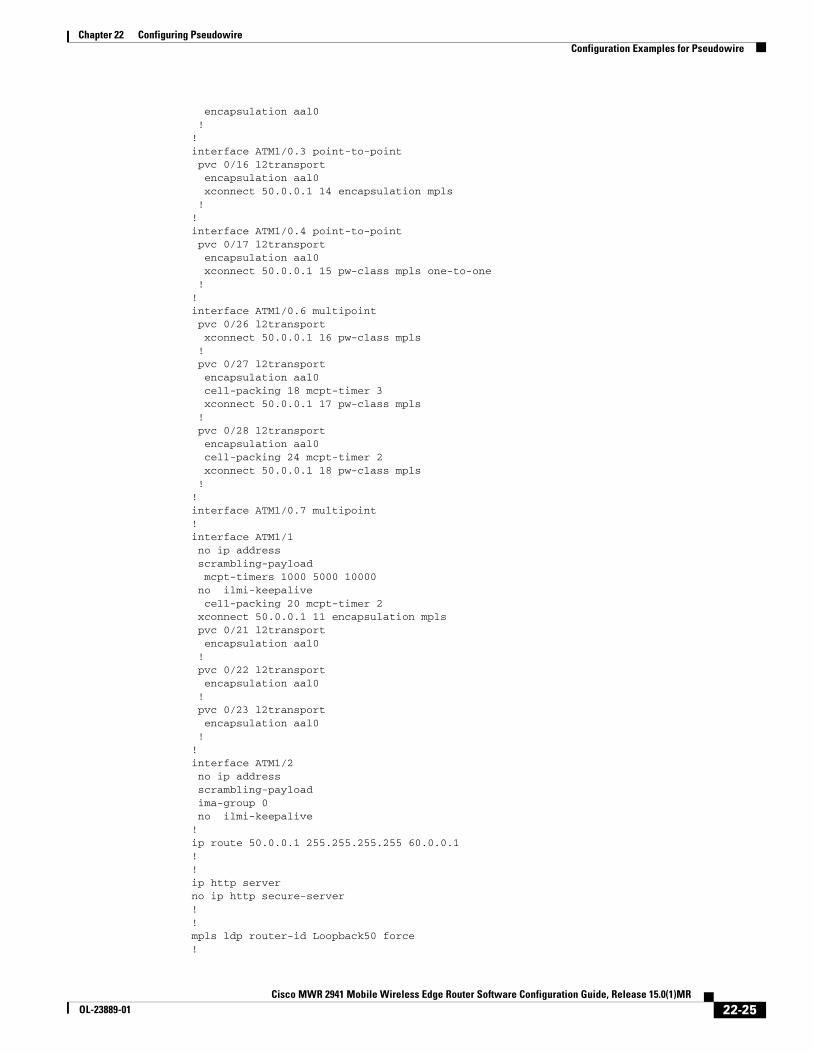
encapsulation aal0 !!interface ATM1/0.3 point-to-point pvc 0/16 l2transport encapsulation aal0 xconnect 50.0.0.1 14 encapsulation mpls !!interface ATM1/0.4 point-to-point pvc 0/17 l2transport encapsulation aal0 xconnect 50.0.0.1 15 pw-class mpls one-to-one !!interface ATM1/0.6 multipoint pvc 0/26 l2transport xconnect 50.0.0.1 16 pw-class mpls ! pvc 0/27 l2transport encapsulation aal0 cell-packing 18 mcpt-timer 3 xconnect 50.0.0.1 17 pw-class mpls ! pvc 0/28 l2transport encapsulation aal0 cell-packing 24 mcpt-timer 2 xconnect 50.0.0.1 18 pw-class mpls !!interface ATM1/0.7 multipoint!interface ATM1/1 no ip address scrambling-payload mcpt-timers 1000 5000 10000 no ilmi-keepalive cell-packing 20 mcpt-timer 2 xconnect 50.0.0.1 11 encapsulation mpls pvc 0/21 l2transport encapsulation aal0 ! pvc 0/22 l2transport encapsulation aal0 ! pvc 0/23 l2transport encapsulation aal0 !!interface ATM1/2 no ip address scrambling-payload ima-group 0 no ilmi-keepalive!ip route 50.0.0.1 255.255.255.255 60.0.0.1!!ip http serverno ip http secure-server!!mpls ldp router-id Loopback50 force!
22-25Cisco MWR 2941 Mobile Wireless Edge Router Software Configuration Guide, Release 15.0(1)MR
OL-23889-01

Chapter 22 Configuring Pseudowire Configuration Examples for Pseudowire
!!line con 0 exec-timeout 0 0line aux 0line vty 0 4 exec-timeout 0 0 login!network-clock-select 1 BITS!end
PWE3 Redundancy ConfigurationThe following example shows a PWE3 Redundancy configuration (Figure 22-3).
Figure 22-3 PWE3 Redundancy Configuration
MWR_1version 12.4service timestamps debug datetime msecservice timestamps log datetime msec!hostname mwr-1!boot-start-markerboot-end-marker!card type e1 0 1card type e1 0 2!ip cef!controller E1 0/0 clock source internal cem-group 0 unframed!controller E1 0/1!controller E1 0/2!controller E1 0/3 clock source internal!controller E1 1/0 mode atm clock source internal!
TDM
ATM
Ethernet
TDM (Primary)
TDM (Backup)
ATM (Primary)
ATM (Backup)
Ethernet (Primary)
Ethernet (Backup)
MWR_1BTS/Node B BSC/RNC
MWR_29.9.9.6/24 9.9.9.8/24 25
3035GigabitEthernet0/1 GigabitEthernet0/1
22-26Cisco MWR 2941 Mobile Wireless Edge Router Software Configuration Guide, Release 15.0(1)MR
OL-23889-01

Chapter 22 Configuring Pseudowire Configuration Examples for Pseudowire
controller E1 1/1!controller E1 1/2!controller E1 1/3 clock source internal!interface CEM0/0cem 0 xconnect 2.2.2.2 1 encapsulation mpls backup peer 2.2.2.2 2 backup delay 20 20 !interface ATM1/0 no ip address scrambling-payload no ilmi-keepalivepvc 0/1 l2transport encapsulation aal0xconnect 2.2.2.2 3 encapsulation mpls backup peer 2.2.2.2 4 backup delay 20 20 !interface Loopback0 no ip address!interface Loopback1 ip address 1.1.1.1 255.255.255.255 load-interval 30!interface Loopback101 no ip address!!interface Vlan 9 ip address 9.9.9.6 255.255.255.0 mpls ip!interface Vlan 10no ip addressno ptp enablexconnect 2.2.2.2 10 encapsulation mplsbackup peer 2.2.2.2 20!interface GigabitEthernet0/1switchport access vlan 9duplex autospeed auto!interface GigabitEthernet0/2switchport access vlan 10duplex autospeed auto!!ip forward-protocol ndip route 2.2.2.2 255.255.255.255 9.9.9.8 !
!control-plane!!line con 0
22-27Cisco MWR 2941 Mobile Wireless Edge Router Software Configuration Guide, Release 15.0(1)MR
OL-23889-01
Chapter 22 Configuring Pseudowire Configuration Examples for Pseudowire
exec-timeout 0 0 logging synchronousline aux 0line vty 0 4 exec-timeout 0 0 password mypassword login!exception data-corruption buffer truncate!end
MWR_2!version 12.4service timestamps debug datetime msecservice timestamps log datetime msec!hostname mwr-pe2!boot-start-markerboot-end-marker!card type e1 0 0card type e1 0 1card type e1 0 2!!ip cef!!controller E1 0/0 cem-group 0 unframed!controller E1 0/1 clock source internal cem-group 0 unframed !controller E1 0/2!controller E1 0/3 clock source internal!controller E1 0/4 clock source internal !controller E1 0/5!controller E1 1/0 mode atm clock source internal!controller E1 1/1 clock source internal !controller E1 1/2 clock source internal !controller E1 1/3 mode atm clock source internal!! Primary
22-28Cisco MWR 2941 Mobile Wireless Edge Router Software Configuration Guide, Release 15.0(1)MR
OL-23889-01

Chapter 22 Configuring Pseudowire Configuration Examples for Pseudowire
interface CEM0/0 cem 0 xconnect 1.1.1.1 1 encapsulation mpls!! Backup interface CEM0/1 cem 0 xconnect 1.1.1.1 2 encapsulation mpls!! Primaryinterface ATM1/0 no ip address scrambling-payload no ilmi-keepalivepvc 0/1 l2transport encapsulation aal0
xconnect 1.1.1.1 3 encapsulation mpls !! Backup interface ATM1/3no ip address scrambling-payload no ilmi-keepalivepvc 0/1 l2transport encapsulation aal0
xconnect 1.1.1.1 4 encapsulation mpls !!interface Loopback1 ip address 2.2.2.2 255.255.255.255!!interface Vlan 9ip address 9.9.9.8 255.255.255.0mpls ip
!interface Vlan 10no ip addressno ptp enablexconnect 1.1.1.1 10 encapsulation mpls!interface Vlan 20no ip addressno ptp enablexconnect 1.1.1.1 20 encapsulation mpls!interface GigabitEthernet0/1switchport access vlan 9duplex autospeed auto!interface GigabitEthernet0/2switchport access vlan 10duplex autospeed auto!interface GigabitEthernet0/3switchport access vlan 20duplex autospeed auto!!ip forward-protocol ndip route 1.1.1.1 255.255.255.255 9.9.9.6
22-29Cisco MWR 2941 Mobile Wireless Edge Router Software Configuration Guide, Release 15.0(1)MR
OL-23889-01

Chapter 22 Configuring Pseudowire Configuration Examples for Pseudowire
!!mpls ldp router-id Loopback1 force!control-plane!no call rsvp-sync!!!line con 0 exec-timeout 0 0 logging synchronousline aux 0line vty 0 4 exec-timeout 0 0 password mypassword login!exception data-corruption buffer truncate!end
TDM over MPLS ConfigurationFigure 22-4 shows a TDM over MPLS configuration. The configuration uses both SAToP and CESoPSN for E1 and T1.
Figure 22-4 TDM over MPLS Configuration
MWR_A!version 12.4service timestamps debug datetime msec localtime show-timezoneservice timestamps log datetime msec localtime show-timezoneno service password-encryption!hostname mwr_A!boot-start-markerboot-end-marker!card type e1 0 0card type e1 0 1enable password xxx!no aaa new-modelclock timezone est -5!
BTSMWR_A
50.50.50.1
E1-1/0 E1-1/0
30.30.30.1
CEM 0/5CEM 0/4CEM 0/1CEM 0/0 (clock )
CEM 0/5CEM 0/4CEM 0/1CEM 0/0
MWR_B
50.50.50.2
BSC
30.30.30.2
GigabitEthernet 0/1 GigabitEthernet 0/1
2530
94
22-30Cisco MWR 2941 Mobile Wireless Edge Router Software Configuration Guide, Release 15.0(1)MR
OL-23889-01

Chapter 22 Configuring Pseudowire Configuration Examples for Pseudowire
ip cef!controller E1 0/0cem-group 0 timeslots 1-31description E1 CESoPSN example!controller E1 0/1clock source internalcem-group 1 unframeddescription E1 SATOP example!controller E1 0/4clock source internalcem-group 4 unframeddescription E1 SATOP example!controller E1 0/5clock source internalcem-group 5 timeslots 1-24description E1 CESoPSN example!controller E1 1/0clock source internal!controller E1 1/1!interface Loopback0ip address 30.30.30.1 255.255.255.255!interface GigabitEthernet0/1ip address 50.50.50.1 255.255.255.0mpls ip!interface CEM0/0no ip addresscem 0 xconnect 30.30.30.2 300 encapsulation mpls!interface CEM0/1no ip addresscem 1 xconnect 30.30.30.2 301 encapsulation mpls!!interface CEM0/4no ip addresscem 4 xconnect 30.30.30.2 304 encapsulation mpls!!interface CEM0/5no ip addresscem 5 xconnect 30.30.30.2 305 encapsulation mpls!!no ip classlessip route 30.30.30.2 255.255.255.255 50.50.50.2!no ip http serverno ip http secure-server!line con 0password xxx
22-31Cisco MWR 2941 Mobile Wireless Edge Router Software Configuration Guide, Release 15.0(1)MR
OL-23889-01

Chapter 22 Configuring Pseudowire Configuration Examples for Pseudowire
loginline aux 0password xxxloginno execline vty 0 4password xxxlogin!network-clock-select 1 BITSend
MWR_B!version 12.4service timestamps debug datetime msec localtime show-timezoneservice timestamps log datetime msec localtime show-timezoneno service password-encryption!hostname mwr_B!boot-start-markerboot-end-marker!card type e1 0 0card type e1 0 1enable password xxx!no aaa new-modelclock timezone est -5!ip cef!controller E1 0/0clock source internalcem-group 0 timeslots 1-31description E1 CESoPSN example!controller E1 0/1clock source internalcem-group 1 unframeddescription E1 SATOP example!controller E1 0/4clock source internalcem-group 4 unframeddescription T1 SATOP example!controller E1 0/5clock source internalcem-group 5 timeslots 1-24description T1 CESoPSN example!controller E1 1/0
!controller E1 1/1!interface Loopback0ip address 30.30.30.2 255.255.255.255!!
22-32Cisco MWR 2941 Mobile Wireless Edge Router Software Configuration Guide, Release 15.0(1)MR
OL-23889-01

Chapter 22 Configuring Pseudowire Configuration Examples for Pseudowire
interface GigabitEthernet0/1ip address 50.50.50.2 255.255.255.0mpls ip!interface CEM0/0no ip addresscem 0 xconnect 30.30.30.1 300 encapsulation mpls!interface CEM0/1no ip addresscem 1 xconnect 30.30.30.1 301 encapsulation mpls!interface CEM0/4no ip addresscem 4 xconnect 30.30.30.1 304 encapsulation mpls!!interface CEM0/5no ip addresscem 5 xconnect 30.30.30.1 305 encapsulation mpls!!no ip classlessip route 30.30.30.1 255.255.255.255 50.50.50.1!no ip http serverno ip http secure-server!line con 0password xxxloginline aux 0password xxxloginno execline vty 0 4password xxxlogin!network-clock-select 1 E1 1/0end
CESoPSN with UDP ConfigurationThe following configuration uses CESoSPN with UDP encapsulation.
Note This section provides a partial configuration intended to demonstrate a specific feature.
interface Loopback0ip address 2.2.2.8 255.255.255.255!pseudowire-class udpClassencapsulation udp
22-33Cisco MWR 2941 Mobile Wireless Edge Router Software Configuration Guide, Release 15.0(1)MR
OL-23889-01

Chapter 22 Configuring Pseudowire Configuration Examples for Pseudowire
protocol noneip local interface Loopback 0!controller E1 0/13clock source internalcem-group 0 timeslots 1-31!interface cem 0/13cem 0xconnect 2.2.2.9 200 pw-class udpClassudp port local 50000 remote 55000
ATM over MPLS ConfigurationThis example shows how to accomplish the following configurations (Figure 22-5):
Note Release 15.0(1)MR does not support N-to-1 VCC Cell Transport for mapping multiple PVCs, 1-to-1 VCC Cell Mode, or PVC mapping.
• AAL5 SDU mode PW on 0/1 PVC 0/100
• N:1 VCC cell mode PW on 0/1 PVC 0/101
• Multiple PVCs N:1 VCC cell mode PW on 0/1.1
• 1:1 VCC cell mode PW on 0/1 PVC 0/102
• Cell-packing for port mode PWs
• VCC cell-relay mode PWs
• PVC mapping for 0/1.1 N:1 VCC cell relay PWs
Figure 22-5 ATM over MPLS Configuration
MWR_A!version 12.4service timestamps debug datetime msecservice timestamps log datetime msec!hostname mwr_A!boot-start-markerboot-end-marker!card type e1 0 0card type e1 0 1
Node-BMWR_A
ATM0/0ATM0/1
2.2.2.2/24 2.2.2.3/24
ATM0/0ATM0/1
MWR_B
88.88.88.88 99.99.99.99
RNC
2530
33
GigabitEthernet0/1 GigabitEthernet0/1
22-34Cisco MWR 2941 Mobile Wireless Edge Router Software Configuration Guide, Release 15.0(1)MR
OL-23889-01
Chapter 22 Configuring Pseudowire Configuration Examples for Pseudowire
logging buffered 4096enable password mypassword!!ip cef!!no ip domain lookup!!controller E1 0/0 mode atm clock source internal!controller E1 0/1 mode atm clock source internal!controller E1 0/2 mode atm clock source internal!controller E1 0/3 mode atm clock source internal!controller E1 0/4!controller E1 0/5!controller E1 1/0!controller E1 1/1!pseudowire-class mpls-exp-5 encapsulation mpls mpls experimental 5!!interface Loopback0 ip address 88.88.88.88 255.255.255.255!interface ATM0/0 no ip address scrambling-payload mcpt-timers 1000 2000 3000 no ilmi-keepalive cell-packing 28 mcpt-timer 3 xconnect 99.99.99.99 100 encapsulation mpls pvc 1/35 l2transport encapsulation aal0 ! pvc 1/36 l2transport encapsulation aal0 ! pvc 1/37 l2transport encapsulation aal0!interface GigabitEthernet0/0!interface ATM0/1 no ip address load-interval 30 scrambling-payload
22-35Cisco MWR 2941 Mobile Wireless Edge Router Software Configuration Guide, Release 15.0(1)MR
OL-23889-01

Chapter 22 Configuring Pseudowire Configuration Examples for Pseudowire
mcpt-timers 1000 2000 3000 no ilmi-keepalive pvc 0/10 ! pvc 0/100 l2transport encapsulation aal5 xconnect 99.99.99.99 1100 encapsulation mpls ! pvc 0/101 l2transport encapsulation aal0 cell-packing 28 mcpt-timer 3 xconnect 99.99.99.99 1101 encapsulation mpls ! pvc 0/102 l2transport encapsulation aal0 cell-packing 28 mcpt-timer 3 xconnect 99.99.99.99 1102 encapsulation mpls ! pvc 0/103 l2transport encapsulation aal0 cell-packing 28 mcpt-timer 3 xconnect 99.99.99.99 1103 pw-class mpls-exp-5 !!interface ATM0/1.1 multipoint cell-packing 28 mcpt-timer 3 xconnect 99.99.99.99 1200 encapsulation mpls pvc 1/35 l2transport encapsulation aal0 pw-pvc 2/135 ! pvc 1/36 l2transport encapsulation aal0 pw-pvc 2/136 ! pvc 1/37 l2transport encapsulation aal0 pw-pvc 2/137 !!interface GigabitEthernet0/1 description interface to 7600 fas 3/5 ip address 2.2.2.2 255.255.255.0 duplex auto speed auto mpls ip no keepalive!interface ATM0/2 no ip address scrambling-payload no ilmi-keepalive!interface ATM0/3 no ip address scrambling-payload no ilmi-keepalive!ip route 99.99.99.99 255.255.255.255 2.2.2.3!!ip http serverno ip http secure-server!
22-36Cisco MWR 2941 Mobile Wireless Edge Router Software Configuration Guide, Release 15.0(1)MR
OL-23889-01

Chapter 22 Configuring Pseudowire Configuration Examples for Pseudowire
!mpls ldp router-id Loopback0!!line con 0 exec-timeout 0 0line aux 0line vty 0 4 exec-timeout 0 0 privilege level 15 password mypasswordlogin
!network-clock-select 1 E1 1/0!end
MWR_B!version 12.4service timestamps debug datetime msecservice timestamps log datetime msec!hostname mwr_B!boot-start-markerboot-end-marker!card type e1 0 0card type e1 0 1logging buffered 4096enable password mypassword!!ip cef!!no ip domain lookup!!controller E1 0/0 mode atm!controller E1 0/1 mode atm!controller E1 0/2 mode atm!controller E1 0/3 mode atm!controller E1 0/4!controller E1 0/5!pseudowire-class mpls-exp-5 encapsulation mpls mpls experimental 5!!interface Loopback0 ip address 99.99.99.99 255.255.255.255
22-37Cisco MWR 2941 Mobile Wireless Edge Router Software Configuration Guide, Release 15.0(1)MR
OL-23889-01

Chapter 22 Configuring Pseudowire Configuration Examples for Pseudowire
!interface ATM0/0 no ip address scrambling-payload mcpt-timers 1000 2000 3000 no ilmi-keepalive cell-packing 28 mcpt-timer 3 xconnect 88.88.88.88 100 encapsulation mpls pvc 1/35 l2transport encapsulation aal0 ! pvc 1/36 l2transport encapsulation aal0 ! pvc 1/37 l2transport encapsulation aal0 !!interface GigabitEthernet0/0!interface ATM0/1 no ip address scrambling-payload mcpt-timers 1000 2000 3000 no ilmi-keepalive pvc 0/2 ! pvc 0/100 l2transport encapsulation aal5 xconnect 88.88.88.88 1100 encapsulation mpls ! pvc 0/101 l2transport encapsulation aal0 cell-packing 28 mcpt-timer 3 xconnect 88.88.88.88 1101 encapsulation mpls ! pvc 0/102 l2transport encapsulation aal0 cell-packing 28 mcpt-timer 3 xconnect 88.88.88.88 1102 encapsulation mpls ! pvc 0/103 l2transport encapsulation aal0 cell-packing 28 mcpt-timer 3 xconnect 88.88.88.88 1103 pw-class mpls-exp-5 !interface ATM0/1.1 multipoint cell-packing 28 mcpt-timer 3 xconnect 88.88.88.88 1200 encapsulation mpls pvc 2/135 l2transport encapsulation aal0 ! pvc 2/136 l2transport encapsulation aal0 ! pvc 2/137 l2transport encapsulation aal0 !!interface GigabitEthernet0/1 ip address 2.2.2.3 255.255.255.0 duplex auto speed auto mpls ip
22-38Cisco MWR 2941 Mobile Wireless Edge Router Software Configuration Guide, Release 15.0(1)MR
OL-23889-01
Chapter 22 Configuring Pseudowire Configuration Examples for Pseudowire
!interface ATM0/2 no ip address scrambling-payload ima-group 0 no ilmi-keepalive!interface ATM0/3 no ip address scrambling-payload ima-group 0 no ilmi-keepalive!ip route 88.88.88.88 255.255.255.255 2.2.2.2!!ip http serverno ip http secure-server!!mpls ldp router-id Loopback0!!line con 0 exec-timeout 0 0line aux 0line vty 0 4 exec-timeout 0 0 password mypassword login!network-clock-select 1 E1 0/0!end
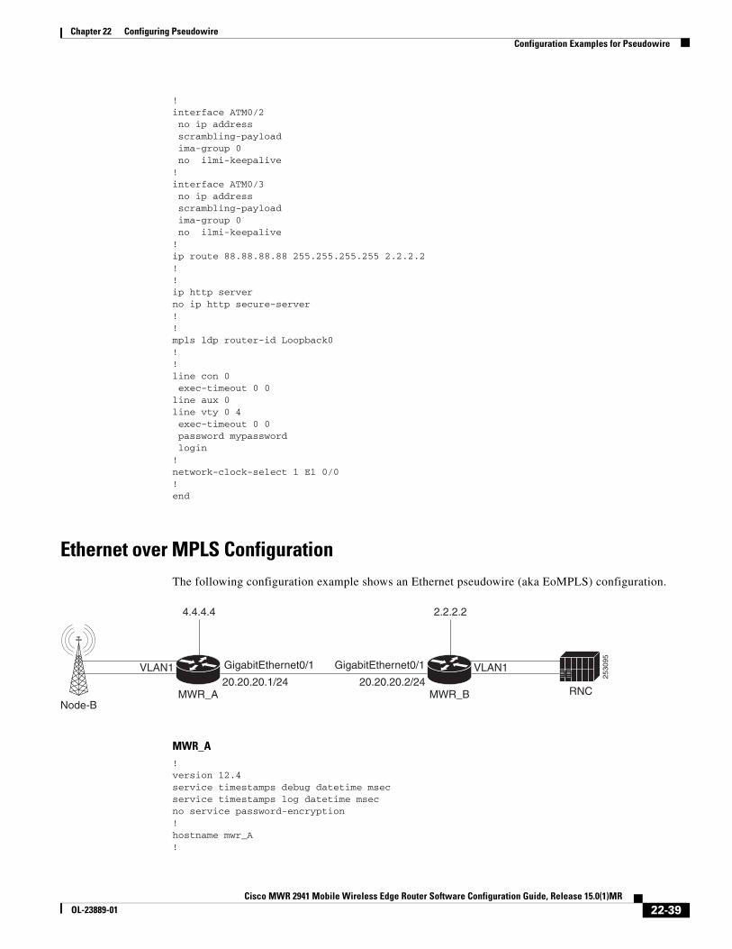
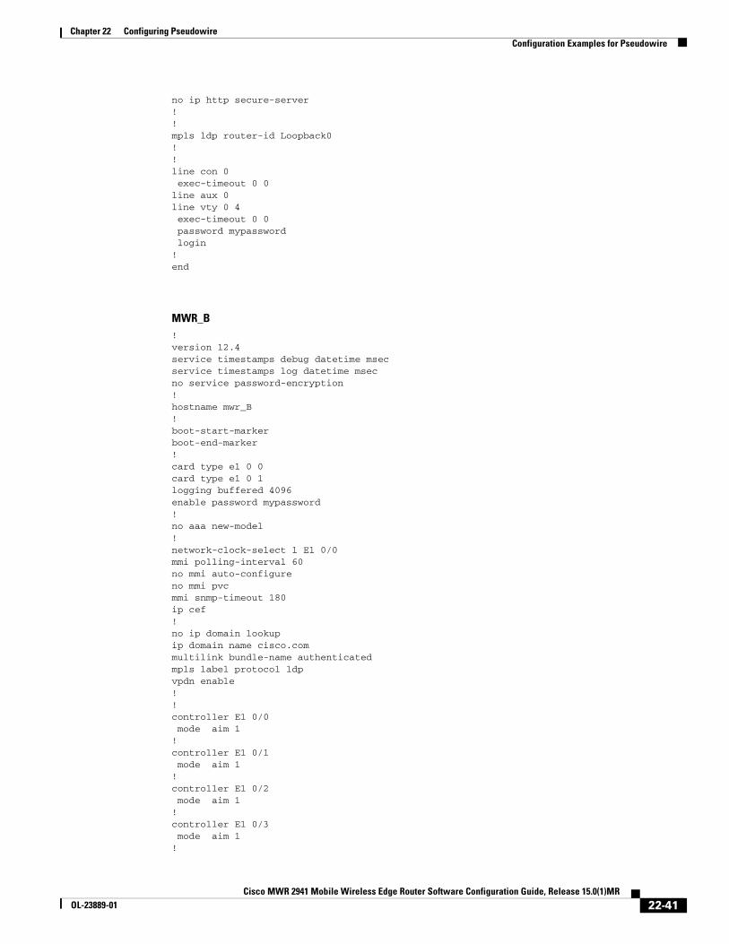
Ethernet over MPLS ConfigurationThe following configuration example shows an Ethernet pseudowire (aka EoMPLS) configuration.
MWR_A!version 12.4service timestamps debug datetime msecservice timestamps log datetime msecno service password-encryption!hostname mwr_A!
Node-BMWR_A
20.20.20.1/24 20.20.20.2/24MWR_B
4.4.4.4 2.2.2.2
RNC
2530
95GigabitEthernet0/1 GigabitEthernet0/1VLAN1 VLAN1
22-39Cisco MWR 2941 Mobile Wireless Edge Router Software Configuration Guide, Release 15.0(1)MR
OL-23889-01
Chapter 22 Configuring Pseudowire Configuration Examples for Pseudowire
boot-start-markerboot-end-marker!card type e1 0 0card type e1 0 1logging buffered 4096enable password mypassword!no aaa new-model!network-clock-select 1 E1 0/0mmi polling-interval 60no mmi auto-configureno mmi pvcmmi snmp-timeout 180ip cef!no ip domain lookupip domain name cisco.commultilink bundle-name authenticatedmpls label protocol ldpvpdn enable!!controller E1 0/0 mode aim 1!controller E1 0/1 mode aim 1!controller E1 0/2 mode aim 1!controller E1 0/3 mode aim 1!controller E1 0/4!controller E1 0/5!interface Loopback0 ip address 4.4.4.4 255.255.255.255!interface GigabitEthernet0/4 switchport trunk allowed vlan 1,2,20,1002-1005 switchport mode trunk!interface GigabitEthernet0/5 switchport trunk allowed vlan 1,2,40,1002-1005 switchport mode trunk!interface Vlan20 ip address 20.20.20.1 255.255.255.0 no ptp enable mpls ip!interface Vlan40 no ip address no ptp enable xconnect 2.2.2.2 10 encapsulation mpls!ip route 2.2.2.2 255.255.255.255 20.20.20.2!no ip http server
22-40Cisco MWR 2941 Mobile Wireless Edge Router Software Configuration Guide, Release 15.0(1)MR
OL-23889-01
Chapter 22 Configuring Pseudowire Configuration Examples for Pseudowire
no ip http secure-server!!mpls ldp router-id Loopback0!!line con 0 exec-timeout 0 0line aux 0line vty 0 4 exec-timeout 0 0 password mypassword login!end
MWR_B!version 12.4service timestamps debug datetime msecservice timestamps log datetime msecno service password-encryption!hostname mwr_B!boot-start-markerboot-end-marker!card type e1 0 0card type e1 0 1logging buffered 4096enable password mypassword!no aaa new-model!network-clock-select 1 E1 0/0mmi polling-interval 60no mmi auto-configureno mmi pvcmmi snmp-timeout 180ip cef!no ip domain lookupip domain name cisco.commultilink bundle-name authenticatedmpls label protocol ldpvpdn enable!!controller E1 0/0 mode aim 1!controller E1 0/1 mode aim 1!controller E1 0/2 mode aim 1!controller E1 0/3 mode aim 1!
22-41Cisco MWR 2941 Mobile Wireless Edge Router Software Configuration Guide, Release 15.0(1)MR
OL-23889-01

Chapter 22 Configuring Pseudowire Configuration Examples for Pseudowire
controller E1 0/4!controller E1 0/5!interface Loopback0 ip address 2.2.2.2 255.255.255.255!interface GigabitEthernet0/4 switchport trunk allowed vlan 1,2,20,1002-1005 switchport mode trunk!interface GigabitEthernet0/5 switchport trunk allowed vlan 1,2,40,1002-1005 switchport mode trunk!interface Vlan20 ip address 20.20.20.2 255.255.255.0 no ptp enable mpls ip!interface Vlan40 no ip address no ptp enable xconnect 4.4.4.4 10 encapsulation mpls!ip route 4.4.4.4 255.255.255.255 20.20.20.1!no ip http serverno ip http secure-server!!mpls ldp router-id Loopback0!!line con 0 exec-timeout 0 0line aux 0line vty 0 4 exec-timeout 0 0 password mypassword login!end
22-42Cisco MWR 2941 Mobile Wireless Edge Router Software Configuration Guide, Release 15.0(1)MR
OL-23889-01