pseudowire channel emulation for transporting frame networks · abstract in this research, an...
TRANSCRIPT
Science and Technology
Journal
والتقنية العلوم هجلة
االلكتروني الوجلة هوقع على النشر تن
2016 / فبراير / بتاريخhttp://www.stj.com.ly
Published Online in
February/ 2016
محفوظة الطبع حقوق 2016 والتقنية العلوم لمجلة
Copyright © STJ 2016 1
تشبيهه باستخدام البرنامج /تصميمه تم pseudowire نفق, في هذا البحث الملخصبروتوكول عبر شبكات frame relay لنقل بيانات نوع GNS3التشبيهيتم الحصول علي اتصال بين طرفي . IP/MPLSتعدد البروتوكول متعدد الوسم/االنترنتframe
Pseudowire Channel Emulation for Transporting Frame
Relay Over MPLS Networks
Anis A.
ABOUSAADA
Khaled M
H Swhli
Osama El-
Ghaly
Dr. Mohamed M.
Elfituri
Dr. Almehdie
A. Agila
Suk Ajoumaa Higher
Institute, Tripoli
Libya
Higher
Institute,
Misurata
Libya
Libya
Telecom &
technology
Co. Libya
Biotechnology
Research Center,
Tripoli Libya
Sebha Higher
Institute,
Sebha Libya
Abstract In this research, an emulated pseudowire channel has been
designed/demonstrated using simulation program GNS3. This pseudowire
channel allowed Service Providers SP to transport layer 2 data such as frame
relay over an IP/MPLS network. A simple topology with 2 Frame Relay
links of the layer 2 technology connected through IP/MPLS network by
using GNS3 has been utilized /demonstrated.
Keywords: Graphical Network Simulator GNS3, Internet Protocol IP,
Multi-Protocol Label Switching MPLS, Frame Relay over MPLS
FoMPLS, Internet Engineering Task Force IETF, Provider Edge PE,
Provider P, Customer Edge CE, network-to-network interface (NNI), Data
Terminal Equipment (DTE), Open Shortest Path First (OSPF),
Asynchronous Transfer Mode (ATM), Tripoli TIP. BEN Benghazi.

Science and Technology
Journal
والتقنية العلوم هجلة
االلكتروني الوجلة هوقع على النشر تن
2016 / فبراير / بتاريخhttp://www.stj.com.ly
Published Online in
February/ 2016
محفوظة الطبع حقوق 2016 والتقنية العلوم لمجلة
Copyright © STJ 2016 2
1. INTRODUCTION Numerous research has been done on solutions facilitate service providers to
converge Layer 2 and Layer 3 services and provide data services over Internet
Protocol (IP) or Multi-Protocol Label Switching MPLS backbone. This paper
presents simulations that allow Layer 2 transport over a Layer 3 infrastructure
using GNS3.It could be simply downloaded from [1]. The GNS3 preparations
were taken from references in [2,3]. This paper is written in 5 sections. In
section 1, an introduction to this research is outlined. Frame relay is introduced
in section 2. MPLS is briefed in section 3. Section 4 has introduced Pseudowire
Emulation technology. Section 5 has introduced experiments on Frame Relay
over MPLS Application. Conclusion & future work is outlined in section6.
2. Frame Relay Frame relay divides data into frames/packets over a wide area network WAN
[4,5, 6]. Each frame has an address the network uses to determine the
destination of the frame. There are two types of frame relay connections,
switched virtual circuits (SVCs) and permanent virtual circuits (PVCs). PVCs
are initially defined as a connection between two sites or end-points.
Establishing a call by using the SVC signaling protocol (Q.933) is comparable
to normal telephone use. The Frame Relay frame is shown in Figure 1. The
flags fields delimit the beginning and end of the frame. Following the leading
flags field are two bytes of address information. Ten bits of these two bytes
make up the actual circuit ID (called the DLCI, for Data Link Connection
Identifier).
Figure 1. Frame Relay Frame
The 10-bit DLCI value is the heart of the Frame Relay header. It identifies the
logical connection that is multiplexed into the physical channel. DLCIs have
Science and Technology
Journal
والتقنية العلوم هجلة
االلكتروني الوجلة هوقع على النشر تن
2016 / فبراير / بتاريخhttp://www.stj.com.ly
Published Online in
February/ 2016
محفوظة الطبع حقوق 2016 والتقنية العلوم لمجلة
Copyright © STJ 2016 3
local significance; that is, the end devices at two different ends of a connection
may use a different DLCI to refer to that same connection.
3. Multi-Protocol Label Switching MPLS MPLS is a Layer 2.5 networking protocol which mixes Layer 2 fast switching
&Layer 3 routing and forwarding [7]. MPLS groups packets to be forwarded
by the same style into a class called Forwarding Equivalence Class (FEC). The
classification of FECs could be based on any combination of source address,
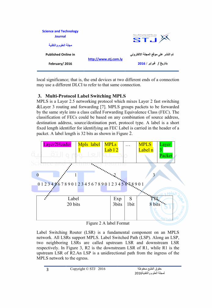
destination address, source/destination port, protocol type. A label is a short
fixed length identifier for identifying an FEC Label is carried in the header of a
packet. A label length is 32 bits as shown in Figure 2.
Layer
3
Packet
MPLS
Label n
… MPLs
Lab l 2
Mpls label
1
Layer2Header
0 1 2 3
0 1 2 3 4 5 6 7 8 9 0 1 2 3 4 5 6 7 8 9 0 1 2 3 4 5 6 7 8 9 0 1
Figure 2 A label Format
Label Switching Router (LSR) is a fundamental component on an MPLS
network. All LSRs support MPLS. Label Switched Path (LSP). Along an LSP,
two neighboring LSRs are called upstream LSR and downstream LSR
respectively. In Figure 3, R2 is the downstream LSR of R1, while R1 is the
upstream LSR of R2.An LSP is a unidirectional path from the ingress of the
MPLS network to the egress.
TTL
8 bits
S
1bit
Exp
3bits
Label
20 bits

Science and Technology
Journal
والتقنية العلوم هجلة
االلكتروني الوجلة هوقع على النشر تن
2016 / فبراير / بتاريخhttp://www.stj.com.ly
Published Online in
February/ 2016
محفوظة الطبع حقوق 2016 والتقنية العلوم لمجلة
Copyright © STJ 2016 4
Figure 3. Label switched path LSR
4. Pseudowire Emulation
Pseudowire emulation forms the foundation for transporting Layer 2 traffic
across IP/MPLS networks [8]. Pseudowires are emulated circuits that carry
service-specific Protocol Data Units (PDU) from one customer device to
another through the service provider network. Figure 4 shows a pseudowire
circuit.
Figure 4 Pseudowire emulation
Pseudowire emulation architecture is shown in Figure 5.A Provider Edge (PE)
device is in the service provider administrative domain. It provides pseudowire
emulation service to a Customer Edge (CE) device that belongs to the
administrative domain of the customer [9].

Science and Technology
Journal
والتقنية العلوم هجلة
االلكتروني الوجلة هوقع على النشر تن
2016 / فبراير / بتاريخhttp://www.stj.com.ly
Published Online in
February/ 2016
محفوظة الطبع حقوق 2016 والتقنية العلوم لمجلة
Copyright © STJ 2016 5
Figure 5. pseudowire emulation architecture
An attachment circuit can be an Ethernet port, an Ethernet virtual local area
network VLAN, a Point To Point Protocol PPP session, a High-Level Data
Link Control (HDLC) link, a Frame Relay data-link connection identifier
(DLCI), an ATM Virtual Path Identifier (VPI)/Virtual Connection Identifier
(VCI) [10].A pseudowire is a virtual circuit between two PE devices that
interconnects two attachment circuits. Table1 shows the different types of
pseudowire application.
Table 1 Pseudowire Channel Types

Science and Technology
Journal
والتقنية العلوم هجلة
االلكتروني الوجلة هوقع على النشر تن
2016 / فبراير / بتاريخhttp://www.stj.com.ly
Published Online in
February/ 2016
محفوظة الطبع حقوق 2016 والتقنية العلوم لمجلة
Copyright © STJ 2016 6
Once establishing a pseudowire channel between two PE devices, native
frames received from an attachment circuit are encapsulated into pseudowire
PDUs and sent over pseudowire channel to the peering PE. When pseudowire
PDUs arrives at the receiving PE device, they are changed back into the native
form and forwarded to the corresponding attachment circuit. Provider (P)
devices form the packet-switched core network and are transparent to CE
devices. Pseudowire emulation involves three protocol layers: PSN layer,
Pseudowire encapsulation layer, Payload layer. For example, when the sub
layer is transporting Frame Relay traffic over MPLS networks, it removes the
Frame Relay header. Figure 6 illustrates the interaction of pseudowire protocol
layers that reside on two peering PE devices [11].
Figure 6 Pseudowire protocol layers.
The benefits that the service provider SP companies acquire from using this
technology:
1. It allows service providers and Enterprises to have a single infrastructure
for both IP and legacy service. For SP move legacy asynchronous transfer
mode ATM/frame relay traffic to IP/MPLS core without interrupting.
2. Customers could have its own routing & quality of services policy.
3. CE routers see each other as a next-hop.

Science and Technology
Journal
والتقنية العلوم هجلة
االلكتروني الوجلة هوقع على النشر تن
2016 / فبراير / بتاريخhttp://www.stj.com.ly
Published Online in
February/ 2016
محفوظة الطبع حقوق 2016 والتقنية العلوم لمجلة
Copyright © STJ 2016 7
4. No routing for customer in MPLS core.
5. Reduced cost by combining multiple core technologies into a single
packet-based network infrastructure.
5. Experiments and Results
Graphical network simulator GNS3 is open source software that simulates
complex networks while being as close as possible to the way real networks
perform. All of this without having dedicated network hardware such as hubs,
routers and switches. In these experiments, GNS3 has been used to simulate
typical router emulators that use original IOS images of the routers that are
developed by Cisco. GNS3 interfaces were utilized to create and configure
virtual routers and topologies in the GNS3 console as shown in figure 7.In
these emulations, frame relay frames over MPLS (FoMPLS) networks by using
pseudowire technology have been transported. Firstly, a simple topology with
two frame relay links connected through IP/MPLS cloud was introduced.
Pseudowire channels to forward Frame Relay traffic for DLCI 101 and DLCI
102 through MPLS core were configured. An MPLS-based core IP network
was configured. Frame Relay IETF encapsulation type was utilized. The
topology utilized is illustrated in Figure 8. In this experiment, it is assumed
that a company that has two branches, one in Tripoli, and the other is in
Benghazi. Both sites were previously used to be connected through a frame
relay network .Recently, the service provider SP company decided to switch
their backbone network to an IP/MPLS network instead of the old frame relay
network. Consequently, the service provider company is going to use a
pseudowire technology.

Science and Technology
Journal
والتقنية العلوم هجلة
االلكتروني الوجلة هوقع على النشر تن
2016 / فبراير / بتاريخhttp://www.stj.com.ly
Published Online in
February/ 2016
محفوظة الطبع حقوق 2016 والتقنية العلوم لمجلة
Copyright © STJ 2016 8
Figure 7. GNS3 Frame Relay over MPLS Simulation.

Science and Technology
Journal
والتقنية العلوم هجلة
االلكتروني الوجلة هوقع على النشر تن
2016 / فبراير / بتاريخhttp://www.stj.com.ly
Published Online in
February/ 2016
محفوظة الطبع حقوق 2016 والتقنية العلوم لمجلة
Copyright © STJ 2016 9
Figure 8. Frame Relay over MPLS topology.
Table 2displays the interfaces, identification and IP addresses used in the
experiments. Table 2 Interfaces and IP addresses
Device Interface IP address
CETIP S1/0 192.168.1.20/24
CEBEN S1/0 192.168.1.10/24
PE1 S2/0 No IP Add assigned
PE1 G1/0 1.1.1.6/30
PE2 S2/0 No IP Add assigned
PE2 G1/0 1.1.1.10/30
P1 G1/0 1.1.1.1/30
P2 G0/0 1.1.1.2/30
P2 G1/0 1.1.1.9/30

Science and Technology
Journal
والتقنية العلوم هجلة
االلكتروني الوجلة هوقع على النشر تن
2016 / فبراير / بتاريخhttp://www.stj.com.ly
Published Online in
February/ 2016
محفوظة الطبع حقوق 2016 والتقنية العلوم لمجلة
Copyright © STJ 2016 10
5.1 Configuring CE routers
In frame relay DLCI mode, PE and CE routers run frame relay LMI between
them. If those CE devices are frame relay switches, configure them to run LMI
NNI. If the CEs are routers, configure one end as LMI Data Circuit
Terminating Equipment (DCE) and leave the other as the default LMI DTE.
Alternatively, configure both routers as LMI NNI so that the CE can provide
status information about its DLCIs to the PE [12,13]. The table 3 describes the
commands that are used to configure the CETIP router.
Table 3 Command list for configuring CETIP router
Command Description
configure terminal Enter global configuration mode
hostname CETIP Assign a name for the router
interface S1/0 Enter interface configuration mode
ip address 192.168.1.20 255.255.255.0 Assign IP address for S1/0
encapsulation frame relay IETF Enable frame relay IETF encapsulation
frame- relay interface-DLCI 101 Assign DLCI 101 for CETIP
frame- relay LMI-type q933a Specify LMI-type as q933a
The configuration of CEBEN was done the same as the configuration of CETIP
with different IP and DLCI number.
5.2 Configuring PE routers
PE routers play a key role in pseudowire emulation. In fact, the conversion
between native circuits and emulated circuits is performed mostly inside PE
routers. The table 4 describes the commands that are used to configure the PE1
router.

Science and Technology
Journal
والتقنية العلوم هجلة
االلكتروني الوجلة هوقع على النشر تن
2016 / فبراير / بتاريخhttp://www.stj.com.ly
Published Online in
February/ 2016
محفوظة الطبع حقوق 2016 والتقنية العلوم لمجلة
Copyright © STJ 2016 11
Table 4 Command list for configuring PE1 router Command Description
configure terminal Enter global configuration mode
hostname PE1 Assign a name for the router
frame-relay switching Enables PVC switching on a Frame
Relay DCE.
pseudowire-class mpls Specifies the name of the pseudowire
class and enters pseudowire class
configuration mode.
encapsulation mpls Specifies that MPLS is used as the data
encapsulation method for tunneling
Layer 2 traffic over the pseudowire.
interface Loopback0 Enter interface configuration mode
and enable virtual interface
ip address 10.0.0.3 255.255.255.255 Assign IP address for Loobback0
interface GigabitEthernet0/0 Enter interface configuration mode
ip address 1.1.1.6 255.255.255.252 Assign IP address for Gi0/0
mpls ip Enable MPLS on the interface
interface Serial1/0 Enter interface configuration mode
encapsulation frame-relay IETF Enable frame relay IETF encapsulation
frame-relay lmi-type q933a Specify lmi-type as q933a
frame-relay intf-type dce Configures interface as Frame Relay
DCE switch.
router OSPF 1 Enable OSPF routing protocol
network 0.0.0.0 255.255.255.255 area 0 Enables OSPF on ALL interfaces.
connect TIP2BEN Serial1/0 102
l2transport
Enable Frame Relay switching and define
a connection called TIP2BEN with a
DLCI 102 on serial interface.
xconnect 10.0.0.4 3 pw-class mpls Binds an attachment circuit to a
pseudowire VC (Virtual Circuit). Assign
id for the pseudowire VC which is we
have chosen number 3
mpls ldp router-id Loopback0 force (Optional) Specifies the preferred
interface for determining the LDP router
ID

Science and Technology
Journal
والتقنية العلوم هجلة
االلكتروني الوجلة هوقع على النشر تن
2016 / فبراير / بتاريخhttp://www.stj.com.ly
Published Online in
February/ 2016
محفوظة الطبع حقوق 2016 والتقنية العلوم لمجلة
Copyright © STJ 2016 12
The configuration of PE2 is the same as the configuration of PE1 with different
IP.
5.3 Configuring P routers
P Router or Provider Router is a Label Switch Router (LSR) that functions as a
transit router of the core network. The P Router typically connected to one or
more PE Routers. P routers were configured with OSPF routing protocol to
route the packets to its destination, and these routers are not aware of the
pseudowire operations and doesn’t involve in it. The table 5 describes the
commands that are used to configure the P1 router.
Table 5 Command list for configuring P1 router
Command Description
configure terminal Enter global configuration mode
hostname PE1 Assign a name for the router
interface Loopback0 Enter interface configuration mode
and enable virtual interface
ip address 10.0.0.1 255.255.255.255 Assign IP address for Loobback0
interface GigabitEthernet0/0 Enter interface configuration mode
ip address 1.1.1.1 255.255.255.252 Assign IP address for Gi0/0
mpls ip Enable MPLS on the interface
interface GigabitEthernet1/0 Enter interface configuration mode
ip address 1.1.1.5 255.255.255.252 Assign IP address for Gi1/0
mpls ip Enable MPLS on the interface
router ospf 1 Enable OSPF routing protocol
network 0.0.0.0 255.255.255.255 area 0 Enables OSPF on ALL interfaces.
5.4 Verification of results
There are some commands that we can use to verify that the configuration has
been done successfully and there is connectivity between the customer’s ends
(CEs). One of the common commands that used to check the connectivity is a

Science and Technology
Journal
والتقنية العلوم هجلة
االلكتروني الوجلة هوقع على النشر تن
2016 / فبراير / بتاريخhttp://www.stj.com.ly
Published Online in
February/ 2016
محفوظة الطبع حقوق 2016 والتقنية العلوم لمجلة
Copyright © STJ 2016 13
ping command. The result that we got from issuing this command at Tripoli CE
router is shown in the Figure 9.
Figure 9. the result of ping command at CETIP
Other command we can use for verification is (debug mpls l2transport
signaling message), and the result of this command is shown in Figure 10. As
we see from the result that the VC is 1 which indicates that the type of the
pseudowire is Frame Relay as we discussed above.
Figure 10 Result of debug mpls L2transport signaling message.
Some commands can be used at PE router to verify the status of Frame Relay
Over MPLS Pseudowire, one of these commands is (show connection all) as
shown in Figure 9 the status of pseudowire connection for the TIP2BEN tunnel
connection is up& running.

Science and Technology
Journal
والتقنية العلوم هجلة
االلكتروني الوجلة هوقع على النشر تن
2016 / فبراير / بتاريخhttp://www.stj.com.ly
Published Online in
February/ 2016
محفوظة الطبع حقوق 2016 والتقنية العلوم لمجلة
Copyright © STJ 2016 14
.
Figure 11. Result of show connection all command.
5.5. Setup CE PE and P routers in GNS3
GNS3 router emulator has been used to use original Cisco IOS images of the
routers. It is important to mount the images on the GNS3 interface so that we
can use them to create and configure virtual routers and topologies in the GNS3
console. Cisco 3600 series router has been chosen for CE router. The process
of mounting IOS images to CE router on GNS3 is as shown below:
Once the IOS images and hypervisors menu option is selected.
On this screen the path to the IOS image can be selected by clicking
the browse button.
Once the browse button is selected the file selection window will
appear.
Browse to the location of the image and select it and press the open
button.
Typically, the Platform will auto-populate if the IOS filename remains within
Cisco’s naming convention and the model options available will populate the
Model dropdown box. In the topology the CE router has one serial interface

Science and Technology
Journal
والتقنية العلوم هجلة
االلكتروني الوجلة هوقع على النشر تن
2016 / فبراير / بتاريخhttp://www.stj.com.ly
Published Online in
February/ 2016
محفوظة الطبع حقوق 2016 والتقنية العلوم لمجلة
Copyright © STJ 2016 15
connected to PE router at the edge of the service provider company. The
process of adding serial interfaces to a CE router is as below:
To configure the CE router, it must be right-clicked and the Configure
option must be selected from the menu.
The menu that will be displayed when a device is right-clicked.
Once Configure is selected the Node configuration window will be
displayed.
To configure the CE router select it from the left pane. The right pane
changes when the device is selected.
The memories and disks tab offers the ability to configure the memory and disk
allocation for the device. The size of the RAM required depends on the specific
image being used; generally, 256 Mbytes is sufficient for most images. The
typical default NVRAM size is 128 Kbytes.
The different options that are available in Slot 0 of the 3600 platform, we will
choose NM-4T which is 4 ports Serial interfaces.
Cisco 7200 series router for PE and P router have been chosen. The process of
mounting IOS images to PE and P router is the same as the process of
mounting IOS images to CE router. In this topology, the PE router has two
interfaces,one is a Giga Ethernet interface connected to P router, and the other
one is a serial interface connected to the CE router. The process of adding
serial interfaces to a PE router is as below:
To configure the PE router, it must be right-clicked and the Configure
option must be selected from the menu. The menu that will be displayed
when a device is right-clicked.
Once Configure is selected the Node configuration window will be
displayed.
To configure the PE router select it from the left pane. The right pane
changes when the device is selected.
The different options that are available in Slot 1 of the 7200 platform, we will
choose PA-4T+ which is 4 port Serial interfaces and PA-GE which is a 1 Giga
Ethernet interface [14].

Science and Technology
Journal
والتقنية العلوم هجلة
االلكتروني الوجلة هوقع على النشر تن
2016 / فبراير / بتاريخhttp://www.stj.com.ly
Published Online in
February/ 2016
محفوظة الطبع حقوق 2016 والتقنية العلوم لمجلة
Copyright © STJ 2016 16
6. Conclusion and Future Work
A simple topology using GNS3 program to transport frame relay over
IP/MPLS network by using pseudowire emulation were demonstrated. Full
connectivity between the two end devices CE at two different sites were
successfully tested. In future work, a topology with different concurrent links
like (ATM, Frame Relay, and Ethernet) could be introduced to study the ability
of pseudowire technology to accommodate different types of legacy layer 2
technologies over a common IP/MPLS network.
References
[1] www.gns3.com.
[2] ]Jason C. Neumann. “The Book of GNS3: Build Virtual Network Labs
Using Cisco, Juniper& more”. 1st Edition 2015, ISBN-13: 978-
1593275549. Pages: 7-17, pages: 31-62, 123-162.
[3] Mason, Andrew G." Cisco Secure Virtual Private Network". Cisco Press,
2002, p. 7.
[4] Jeff T. Buckwalter. “Frame Relay: Technology and Practice “, Addison-
Wesley Professional, 1st Edition 2000. ISBN-13: 078-5342485240. Pages:
23-137.
[5] Bruce S. Davie.& Y. Rekhetr “MPLS Technology and
Applications”. MK Publishers 1st Edition, ISBN-13: 978-
1558606562, Pages:25-145.
[6] http://www.ixiacom.com/sites/default/files/resources/blackbook/adv
anced_mpls_915-2602-01_revi_0.pdf [7] JUHA SALMELIN, ESA METSALA, “MOBILE BACKHAUL”. 1
st Edition 2012,
Wily, Pages 19-57.
[8] Philippe VASSEUR ET AL.,Definitive MPLS Network Designs.
2005 Cisco Press. Pages: 15-173.
[9] H. Alarabi, W. Benrajab, “Frame Relay Over MPLS”, 2015
graduation project, Suk Ajouma Higher Institute.