ps5580 rs232 and lan command - planar · pdf file• command is the command code. ......
TRANSCRIPT

Planar PS5580 RS232 and LAN Command Protocol

Copyright © 4 Feb 2014 by Planar Systems, Inc. All rights reserved.Contents of this publication may not be reproduced in any form without permission of Planar Systems, Inc.
Trademark Credits Windows™ is a trademark of Microsoft Corp.All other names are trademarks or registered trademarks of their respective companies.
DisclaimerThe information contained in this document is subject to change without notice.
Planar Systems, Inc., makes no warranty of any kind with regard to this material. While every precaution has been taken in the preparation of this manual, the Company shall not be liable for errors or omissions contained herein or for incidental or consequential damages in connection with the furnishing, performance, or use of this material.
Warranty and Service PlansPlanar warranty and service plans will help you maximize your investment by providing great support, display uptime, and performance optimization. From post-sale technical support to a full suite of depot services, our services are performed by trained Planar employees. When you purchase a Planar product, you get more than a display, you get the service and support you need to maximize your investment. To find the latest warranty and service information regarding your Planar product, please visit:http://www.planarcontrolroom.com/support
Part Number: 020-1253-00C
PS5580 RS232 and LAN Command Protocol
Table of ContentsCommand Protocol Description. . . . . . . . . . . . . . . . . . . . . . . . . . . . . . . . . . . . . . . . . . . . . . . . . . . . . . . . . . . . . . . . . . . .1
Command Protocol . . . . . . . . . . . . . . . . . . . . . . . . . . . . . . . . . . . . . . . . . . . . . . . . . . . . . . . . . . . . . . . . . . . . . . . . . . . . . .1Communications Link. . . . . . . . . . . . . . . . . . . . . . . . . . . . . . . . . . . . . . . . . . . . . . . . . . . . . . . . . . . . . . . . . . . . . . .1Communication Settings . . . . . . . . . . . . . . . . . . . . . . . . . . . . . . . . . . . . . . . . . . . . . . . . . . . . . . . . . . . . . . . . . . .1Directly Addressed Command Format. . . . . . . . . . . . . . . . . . . . . . . . . . . . . . . . . . . . . . . . . . . . . . . . . . . . . . .1Broadcast Command Format. . . . . . . . . . . . . . . . . . . . . . . . . . . . . . . . . . . . . . . . . . . . . . . . . . . . . . . . . . . . . . . .2
Command / Response Examples . . . . . . . . . . . . . . . . . . . . . . . . . . . . . . . . . . . . . . . . . . . . . . . . . . . . . . . . . . . . . . . . . .2
Commands Supported in the PS5580 Display . . . . . . . . . . . . . . . . . . . . . . . . . . . . . . . . . . . . . . . . . . . . . . . . . . . . .4
Notes for Commands Table . . . . . . . . . . . . . . . . . . . . . . . . . . . . . . . . . . . . . . . . . . . . . . . . . . . . . . . . . . . . . . . 17Get LCD Status Response . . . . . . . . . . . . . . . . . . . . . . . . . . . . . . . . . . . . . . . . . . . . . . . . . . . . . . . . . . . . . . . . . 18

Command Protocol
PS5580 RS232 and LAN Command Protocol 1
Command Protocol DescriptionThis document specifies the protocols used on the PS5580 RS232 and LAN connectors.
Command Protocol
Communications Link
Communication between the host and the display can be either a standard RS232 connection or a standard LAN connection.
Communication Settings
The RS232 connections uses these settings:
• Straight-thru DB9 male-to-female cable• 115200 baud rate• 8 data bits• 1 stop bit• No parity bit• No HW (RTS/CTS or SW (XON/XOFF) flow control
The LAN connections is used by initiating a TCP connection to port 9761.
Directly Addressed Command Format
Commands that are sent to only one display are directly addressed commands. Directly addressed commands and responses have the following format:
STX Command Length Group ID Multi ID Mode Data Checksum ETX
Send to Display 1 byte 1 byte 1 byte 1 byte 1 byte 1 byte n bytes N/A 1 byte
Received from Display 1 byte 1 byte 1 byte 1 byte 1 byte 1 byte n bytes 1 byte 1 byte

Broadcast Command Format
PS5580 RS232 and LAN Command Protocol 2
Definition of terms in Directly Addressed Command Format table:
• STX is the ascii STX character (0x02).• Command is the command code.• Length is the number of bytes in the Group ID, Multi ID, Mode and Data fields.• Group ID is the Group ID value in the display’s Option menu. A=1, B=2, C=3, etc.• Multi ID is the Monitor ID value in the display’s Tiling menu.• Mode selects whether the command is a Read command or a Write command.
• Read = 0x00• Write = 0x02
• Data contains values specific to the selected command.• Checksum is the one's complement of the following response fields: STX,
Command, Length, Group ID, Multi ID, Mode, Data (i.e. the sum of these fields and the checksum field, modulo 256, will be 0xFF).
• ETX is the ascii ETX character (0x03).
Broadcast Command Format
Commands that are sent to all displays are broadcast commands. They have the this format:
Definition of terms in Broadcast Command Format table:
• STX is the ascii STX character (0x02).• Command is the command code.• Length is the number of bytes in the Group ID, Multi ID and Data fields.• Group ID is set to 0x00.• Multi ID is set to 0x00• Data contains values specific to the selected command.• ETX is the ascii ETX character (0x03).
The displays do not send responses to broadcast commands.
Command / Response ExamplesExample: Power query when unit is powered on (Group ID = A, Multi ID = 4)
STX Command Length Group ID Multi ID Data ETX
Send to Display 1 byte 1 byte 1 byte 1 byte 1 byte n bytes 1 byte
STX CMD LEN GID MID MOD DAT CHK ETX
Command 02 10 03 01 04 00 03
Response 02 10 04 01 04 00 01 E3 03

Command / Response Examples
PS5580 RS232 and LAN Command Protocol 3
Example: Set power to off (Group ID = B, Multi ID = 1)
Example: Set power to off (broadcast)
STX CMD LEN GID MID MOD DAT CHK ETX
Command 02 11 03 02 01 02 03
Response 02 11 03 02 01 02 E4 03
STX CMD LEN GID MID MOD DAT CHK ETX
Command 02 11 02 00 00 03
Response [None]
PS5580 RS232 and LAN Command Protocol 4
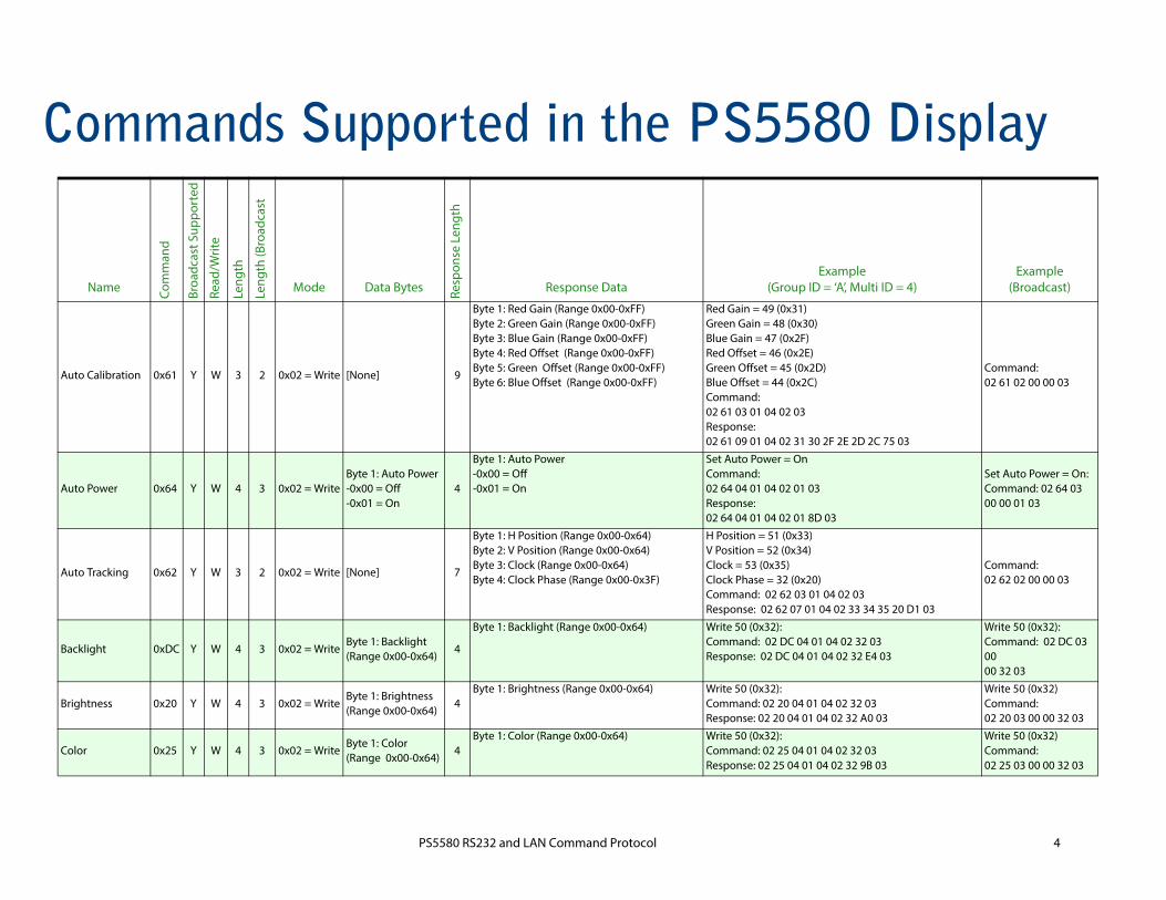
Commands Supported in the PS5580 Display
Name Com
man
d
Broa
dcas
t Sup
port
ed
Read
/Writ
e
Leng
th
Leng
th (B
road
cast
Mode Data Bytes Resp
onse
Len
gth
Response DataExample
(Group ID = ‘A’, Multi ID = 4)Example
(Broadcast)
Auto Calibration 0x61 Y W 3 2 0x02 = Write [None] 9
Byte 1: Red Gain (Range 0x00-0xFF)Byte 2: Green Gain (Range 0x00-0xFF)Byte 3: Blue Gain (Range 0x00-0xFF)Byte 4: Red Offset (Range 0x00-0xFF)Byte 5: Green Offset (Range 0x00-0xFF)Byte 6: Blue Offset (Range 0x00-0xFF)
Red Gain = 49 (0x31)Green Gain = 48 (0x30)Blue Gain = 47 (0x2F)Red Offset = 46 (0x2E)Green Offset = 45 (0x2D)Blue Offset = 44 (0x2C)Command:02 61 03 01 04 02 03Response:02 61 09 01 04 02 31 30 2F 2E 2D 2C 75 03
Command:02 61 02 00 00 03
Auto Power 0x64 Y W 4 3 0x02 = WriteByte 1: Auto Power-0x00 = Off-0x01 = On
4
Byte 1: Auto Power-0x00 = Off-0x01 = On
Set Auto Power = OnCommand: 02 64 04 01 04 02 01 03Response: 02 64 04 01 04 02 01 8D 03
Set Auto Power = On:Command: 02 64 03 00 00 01 03
Auto Tracking 0x62 Y W 3 2 0x02 = Write [None] 7
Byte 1: H Position (Range 0x00-0x64)Byte 2: V Position (Range 0x00-0x64)Byte 3: Clock (Range 0x00-0x64)Byte 4: Clock Phase (Range 0x00-0x3F)
H Position = 51 (0x33)V Position = 52 (0x34)Clock = 53 (0x35)Clock Phase = 32 (0x20)Command: 02 62 03 01 04 02 03Response: 02 62 07 01 04 02 33 34 35 20 D1 03
Command: 02 62 02 00 00 03
Backlight 0xDC Y W 4 3 0x02 = WriteByte 1: Backlight (Range 0x00-0x64)
4
Byte 1: Backlight (Range 0x00-0x64) Write 50 (0x32): Command: 02 DC 04 01 04 02 32 03Response: 02 DC 04 01 04 02 32 E4 03
Write 50 (0x32):Command: 02 DC 03 00 00 32 03
Brightness 0x20 Y W 4 3 0x02 = WriteByte 1: Brightness(Range 0x00-0x64)
4Byte 1: Brightness (Range 0x00-0x64) Write 50 (0x32):
Command: 02 20 04 01 04 02 32 03Response: 02 20 04 01 04 02 32 A0 03
Write 50 (0x32)Command: 02 20 03 00 00 32 03
Color 0x25 Y W 4 3 0x02 = WriteByte 1: Color (Range 0x00-0x64)
4Byte 1: Color (Range 0x00-0x64) Write 50 (0x32):
Command: 02 25 04 01 04 02 32 03Response: 02 25 04 01 04 02 32 9B 03
Write 50 (0x32)Command: 02 25 03 00 00 32 03

PS5580 RS232 and LAN Command Protocol 5
Color SpaceConfiguration
0xB4 Y W 4 3 0x02 = Write
Byte 1: Color Space- 0x00 = Auto- 0x01 = RGB PC- 0x02 = RGB Video
4
Byte 1: Color Space- 0x00 = Auto- 0x01 = RGB PC- 0x02 = RGB Video
Set Color Space = Auto:Command: 02 B4 04 01 04 02 00 03Response: 02 B4 04 01 04 02 00 3E 03
Set Color Space = AutoCommand: 02 B4 03 00 00 00 03
Color Temperature
0x26 Y W 4 3 0x02 = Write
Byte 1: Color Temp- 0x01 = 4000K- 0x02 = 6500K- 0x03 = 10000K- 0x04 = User Mode
4
Byte 1: Color Temp- 0x01 = 4000K- 0x02 = 6500K- 0x03 = 10000K- 0x04 = User Mode
Set Color Temperature = 6500KCommand: 02 26 04 01 04 02 02 03Response: 02 26 04 01 04 02 02 CA 03
Set Color Temp = 6500K:Command: 02 26 03 00 00 02 03
Contrast 0x21 Y W 4 3 0x02 = WriteByte 1: Contrast(Range 0x00-0x64)
4Byte 1: Contrast (Range 0x00-0x64) Write 50 (0x32):
Command: 02 21 04 01 04 02 32 03Response: 02 21 04 01 04 02 32 9F 03
Write 50 (0x32)Command: 02 21 03 00 00 32 03
DHCP Off 0x74 Y W 3 2 0x02 = Write [None] 3[None] Command: 02 74 03 01 04 02 03
Response: 02 74 03 01 04 02 7F 03 1Command: 02 74 02 00 00 03
DHCP On 0x73 Y W 3 2 0x02 = Write [None] 3[None] Command: 02 73 03 01 04 02 03
Response: 02 73 03 01 04 02 80 03 1Command: 02 73 02 00 00 03
Factory Reset 0xBB Y W 3 2 0x02 = Write [None] 3[None] Command: 02 BB 03 01 04 02 03
Response: 02 BB 03 01 04 02 38 03 Command: 02 BB 02 00 00 03
Frame Comp - Off 0x2D Y W 3 2 0x02 = Write [None] 3[None] Command: 02 2D 03 01 04 02 03
Response: 02 2D 03 01 04 02 C6 03Command: 02 2D 02 00 00 03
Frame Comp - On 0x2C Y W 3 2 0x02 = Write [None] 3[None] Command: 02 2C 03 01 04 02 03
Response: 02 2C 03 01 04 02 C7 03Command: 02 2C 02 00 00 03
Gamma 0x35 Y W 4 3 0x02 = WriteByte 1: Gamma- 0x00 = 1.8- 0x01 = 2.2
4Byte 1: Gamma- 0x00 = 1.8- 0x01 = 2.2
Set Gamma = 2.2:Command: 02 35 04 01 04 02 01 03Response: 02 35 04 01 04 02 01 BC 03
Set Gamma = 2.2:Command: 02 35 03 00 00 01 03
Name Com
man
d
Broa
dcas
t Sup
port
ed
Read
/Writ
e
Leng
th
Leng
th (B
road
cast
Mode Data Bytes Resp
onse
Len
gth
Response DataExample
(Group ID = ‘A’, Multi ID = 4)Example
(Broadcast)

PS5580 RS232 and LAN Command Protocol 6
Get Firmware Version
0xF9 N R 3 N/A 0x00 = Read [None] 19
Bytes 1-2: Scaler Firmware Year (last two digits)Bytes 3-4: Scaler Firmware Month (two digits)Bytes 5-6: Scaler Firmware Day (two digits)Bytes 7-8: Scaler Firmware Revision (two digits)Bytes 9-10: Micom Firmware Year (last two digits)Bytes 11-12: Micom Firmware Month (two digits)Bytes 13-14: Micom Firmware Day (two digits)Bytes 15-16: Micom Firmware Revision (two digits)
Scaler Firmware Year = 2013
Scaler Firmware Month = NovemberScaler Firmware Day = 21Scaler Firmware Revision = 00
Micom Firmware Year = 2013
Micom Firmware Month = October
Micom Firmware Day = 15Micom Firmware Revision = 02Command: 02 F9 03 01 04 00 03Response: 02 F9 13 01 04 00 01 03 01 01 02 01 00 00 01 03 01 00 01 05 00 02 D6 03
N/A
Get IP Address 0x7A N R 3 N/A 0x00 = Read [None] 30
Byte 1: LAN On/Off- 0x00 = Off- 0x01 = OnByte 2: DHCP- 0x00 = Off- 0x01 = OnBytes 3-6: IP AddressBytes 7-10: Subnet MaskBytes 11-14: Default GatewayBytes 15-18: Primary DNSBytes 19-22: Secondary DNSBytes 23-27: Port Number
LAN On/Off = OnDHCP = OnIP Address = 192.168.12.2Subnet Mask = 255.255.255.0Default Gateway = 192.168.12.1Primary DNS = 192.168.12.100Secondary DNS = 192.168.12.101Port Number = 9761
Cmmand: 02 7A 03 01 04 00 03Response: 02 7A 1E 01 04 00 01 01 C0 A8 0C 02 FF FF FF 00 C0 A8 0C 01 C0 A8 0C 64 C0 A8 0C 65 00 09 07 06 01 AE 03
N/A
Name Com
man
d
Broa
dcas
t Sup
port
ed
Read
/Writ
e
Leng
th
Leng
th (B
road
cast
Mode Data Bytes Resp
onse
Len
gth
Response DataExample
(Group ID = ‘A’, Multi ID = 4)Example
(Broadcast)

PS5580 RS232 and LAN Command Protocol 7
Get LCD Status 0x87 N R 3 N/A 0x00 = Read [None] 12
Byte 1: Power Status- 0x00 = Off- 0x01 = OnByte 2: Input Source- 0x01 = DisplayPort- 0x02 = HDMI 1- 0x03 = HDMI 2- 0x04 = DVI- 0x05 = PCByte 3: Resolution2
Byte 4: Color Temp- 0x01 = 4000K- 0x02 = 6500K- 0x03 = 10000K- 0x04 = User ModeByte 5: Power Save- 0x00 = Off- 0x01 = OnByte 6: Auto Power- 0x00 = Off- 0x01 = OnByte 7 = Frame Comp- 0x00 = Off- 0x01 = OnByte 8: Scan Mode- 0x00 = Overscan Off- 0x01 = Overscan OnByte 9: Loop Source- 0xD2 = HDMI 1- 0xD3 = HDMI 2- 0xD4 = DVI
Power Status = On
Input Source = DVI
Resolution = 1080p/60Color Temp = User Mode
Power Save = On
Auto Power = On
Frame Comp = On
Scan Mode = Overscan Off
Loop Source = HDMI 1Command = 02 87 03 01 04 00 03Response: 02 87 0C 01 04 00 01 04 3A 04 01 01 01 00 D2 4D 03
N/A
Get MAC Address 0xD0 N R 3 N/A 0x00 = Read [None] 9Bytes 1-6: MAC Address in hex MAC Address = 00:0A:36:E0:00:01
Command: 02 D0 03 01 04 00 03Response: 02 D0 09 01 04 00 00 0A 36 E0 00 01FE 03
N/A
Name Com
man
d
Broa
dcas
t Sup
port
ed
Read
/Writ
e
Leng
th
Leng
th (B
road
cast
Mode Data Bytes Resp
onse
Len
gth
Response DataExample
(Group ID = ‘A’, Multi ID = 4)Example
(Broadcast)

PS5580 RS232 and LAN Command Protocol 8
Get Model Name and Serial Number
0xB9 N R 3 N/A 0x00 = Read [None] 25
Bytes 1-9: Model NameBytes 10-22: Serial Number
Model Name = PS5580Serial Number = ABCDEFGHIJKLMCommand: 02 B9 03 01 04 00 03Response: 02 B9 19 01 04 00 50 53 35 35 38 30 00 00 00 41 42 43 44 45 46 47 48 49 4A 4B 4C 4D 16 03
N/A
Get OSD Control Data
0x98 N R 3 N/A 0x00 = Read [None] 10
Byte 1: OSD Language- 0x00 = EnglishByte 2: OSD Timeout (Range 0x05-0x78)
Byte 3: OSD H Position (Range 0x00-0x64)Byte 4: OSD V Position (Range 0x00-0x64)Byte 5: OSD Rotation- 0x00 = No Rotation- 0x01 = H Mirror- 0x02 = V MirrorByte 6: Info Timeout (Range 0x00, 0x03-0x0A)4
Byte 7: Transparency (Range 0x00-0x0F)
OSD Language = 0
OSD Timeout = 10 seconds3
H Position = 50V Position = 50OSD Rotation = No Rotation
Info Timeout = 10
Transparency = 0Command: 02 98 03 01 04 00 03Response: 02 98 0A 01 04 00 00 0A 32 32 00 0A 00 DE 03
N/A
Get PC Setup Control Data
0x96 N R 3 N/A 0x00 = Read [None] 13
Byte 1: ADC Red Gain (Range 0x00-0x64)Byte 2: ADC Green Gain (Range 0x00-0x64)Byte 3: ADC Blue Gain (Range 0x00-0x64)Byte 4: ADC Red Offset (Range 0x00-0x64)Byte 5: ADC Green Offset (Range 0x00-0x64)Byte 6: ADC Blue Offset (Range 0x00-0x64)Byte 7: H Position (Range 0x00-0x64)Byte 8: V Position (Range 0x00-0x64)Byte 9: Clock (Range 0x00-0x64)Byte 10: Clock Phase (Range 0x00-0x3F)
ADC Red Gain = 51ADC Green Gain = 52ADC Blue Gain = 53ADC Red Offset = 49ADC Green Offset = 48ADC Blue Offset = 47H Position = 50V Position = 50Clock = 50Clock Phase = 32Command: 02 96 03 01 04 00 03Response: 02 96 0D 01 04 00 33 34 35 31 30 2F 32 32 32 20 73 03
N/A
Name Com
man
d
Broa
dcas
t Sup
port
ed
Read
/Writ
e
Leng
th
Leng
th (B
road
cast
Mode Data Bytes Resp
onse
Len
gth
Response DataExample
(Group ID = ‘A’, Multi ID = 4)Example
(Broadcast)

PS5580 RS232 and LAN Command Protocol 9
Get Picture Control Data
0x90 N R 3 N/A 0x00 = Read [None] 24
Byte 1: Input Source- 0x01 = DisplayPort- 0x02 = HDMI 1- 0x03 = HDMI 2- 0x04 = DVI- 0x05 = PCByte 2: Brightness (Range 0x00-0x64)Byte 3: Contrast (Range 0x00-0x64)Byte 4: Sharpness (Range 0x00-0x18)Byte 5: Tint (Range 0x4D-0xB1)5
Byte 6: Color (Range 0x00-0x64)Byte 7: Backlight (Range 0x00-0x64)Byte 8: Color Temp- 0x01 = 4000K- 0x02 = 6500K- 0x03 = 10000K- 0x04 = User ModeByte 9: Digital Red Gain (Range 0x00-0x64)Byte 10: Digital Green Gain (Range 0x00-0x64)Byte 11: Digital Blue Gain (Range 0x00-0x64)Byte 12: Digital Red Offset (Range 0x00-0x64)Byte 13: Digital Green Offset (Range 0x00-0x64)Byte 14: Digital Blue Offset (Range 0x00-0x64)Byte 15: Analog Red Gain (Range 0x00-0x64)Byte 16: Analog Green Gain (Range 0x00-0x64)Byte 17: Analog Blue Gain (Range 0x00-0x64)Byte 18: Analog Red Offset (Range 0x00-0x64)Byte 19: Analog Green Offset (Range 0x00-0x64)Byte 20: Analog Blue Offset (Range 0x00-0x64)Byte 21: Gamma- 0x00 = 1.8- 0x01 = 2.2
Input Source = DVI
Brightness = 50 (0x32)Contrast = 51 (0x33)Sharpness = 10 (0x0A)Tint = 0 (0x7F)Color = 52 (0x34)Backlight = 53 (0x35)Color Temp = 6500K
Digital Red Gain = 49 (0x31)Digital Green Gain = 48 (0x30)Digital Blue Gain = 47 (0x2F)Digital Red Offset = 46 (0x2E)Digital Green Offset = 45 (0x2D)
Digital Blue Offset = 44 (0x2C)Analog Red Gain = 43 (0x2B)Analog Green Gain = 42 (0x2A)
Analog Blue Gain = 41 (0x29)Analog Red Offset = 40 (0x28)Analog Green Offset = 39 (0x27)
Analog Blue Offset = 38 (0x26)
Gamma = 2.2Command: 02 90 03 01 04 00 03Response: 02 90 18 01 04 00 04 32 33 0A 7F 34 35 02 31 30 2F 2E 2D 2C 2B 2A 29 28 27 26 01 E8 03
N/A
Name Com
man
d
Broa
dcas
t Sup
port
ed
Read
/Writ
e
Leng
th
Leng
th (B
road
cast
Mode Data Bytes Resp
onse
Len
gth
Response DataExample
(Group ID = ‘A’, Multi ID = 4)Example
(Broadcast)

PS5580 RS232 and LAN Command Protocol 10
ID Configuration 0xFF N W 5 N/A 0x02 = Write
Byte 1: Group ID (Range 0x01-0xFF)Byte 2: Multi ID (Range 0x01-0xFF)
5
Byte 1: Group ID (Range 0x01-0xFF)Byte 2: Multi ID (Range 0x01-0xFF)
Command: 02 FF 05 01 04 02 01 04 03Response: 02 FF 05 01 04 02 01 04 ED 03
N/A
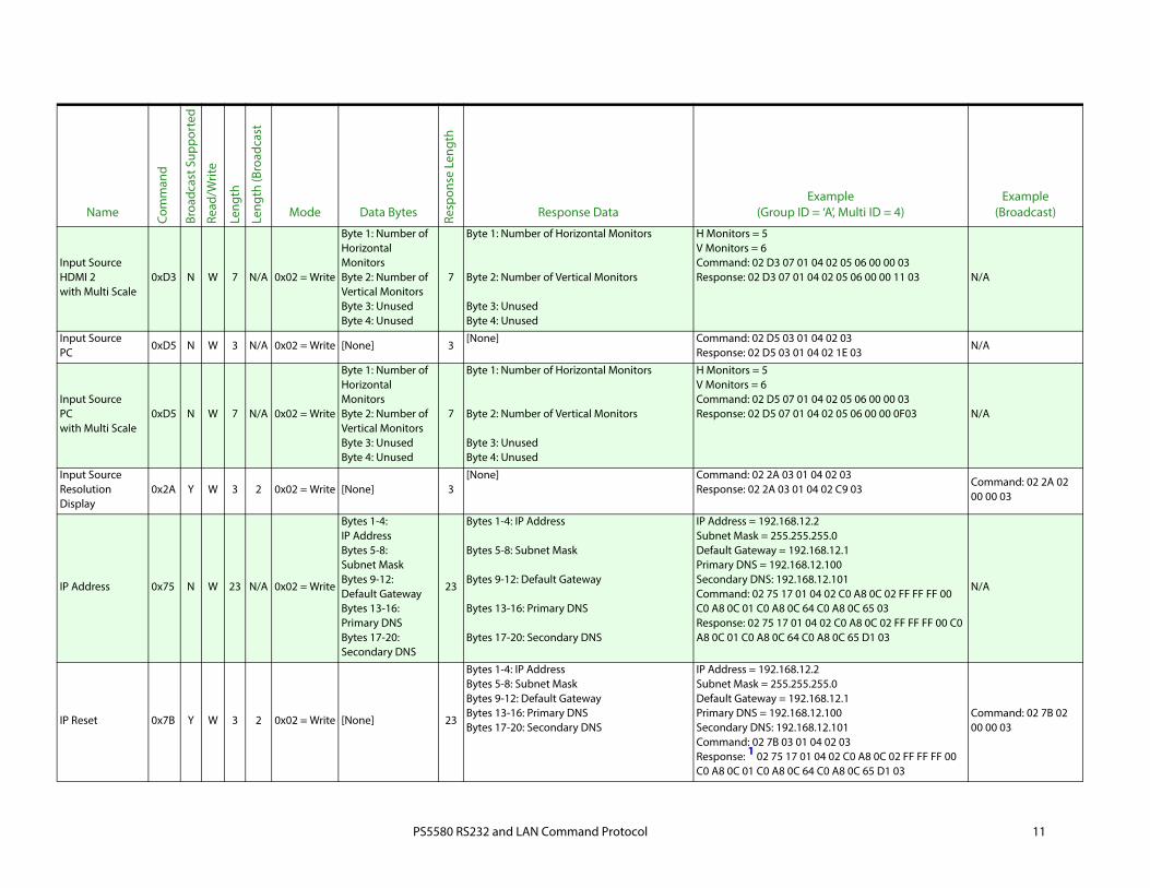
Input Source DisplayPort
0xD1 N W 3 N/A 0x02 = Write [None] 3[None] Command: 02 D1 03 01 04 02 03
Response: 02 D1 03 01 04 02 22 03N/A
Input SourceDisplayPortwith Multi Scale
0xD1 N W 7 N/A 0x02 = Write
Byte 1: Number of Horizontal MonitorsByte 2: Number of Vertical MonitorsByte 3: UnusedByte 4: Unused
7
Byte 1: Number of Horizontal Monitors
Byte 2: Number of Vertical Monitors
Byte 3: UnusedByte 4: Unused
H Monitors = 5V Monitors = 6Command: 02 D1 07 01 04 02 05 06 00 00 03Response: 02 D1 07 01 04 02 05 06 00 00 13 03 N/A
Input Source DVI
0xD4 N W 3 N/A 0x02 = Write [None] 3[None] Command: 02 D4 03 01 04 02 03
Response: 02 D4 03 01 04 02 1F 03N/A
Input Source DVIwith Multi Scale
0xD4 N W 7 N/A 0x02 = Write
Byte 1: Number of Horizontal MonitorsByte 2: Number of Vertical MonitorsByte 3: UnusedByte 4: Unused
7
Byte 1: Number of Horizontal Monitors
Byte 2: Number of Vertical Monitors
Byte 3: UnusedByte 4: Unused
H Monitors = 5V Monitors = 6Command: 02 D4 07 01 04 02 05 06 00 00 03Response: 02 D4 07 01 04 02 05 06 00 00 10 03 N/A
Input Source HDMI 1
0xD2 N W 3 N/A 0x02 = Write [None] 3[None] Command: 02 D2 03 01 04 02 03
Response: 02 D2 03 01 04 02 21 03N/A
Input Source HDMI 1with Multi Scale
0xD2 N W 7 N/A 0x02 = Write
Byte 1: Number of Horizontal MonitorsByte 2: Number of Vertical MonitorsByte 3: UnusedByte 4: Unused
7
Byte 1: Number of Horizontal Monitors
Byte 2: Number of Vertical Monitors
Byte 3: UnusedByte 4: Unused
H Monitors = 5V Monitors = 6Command: 02 D2 07 01 04 02 05 06 00 00 03Response: 02 D2 07 01 04 02 05 06 00 00 12 03 N/A
Input Source HDMI 2
0xD3 N W 3 N/A 0x02 = Write [None] 3[None] Command: 02 D3 03 01 04 02 03
Response: 02 D3 03 01 04 02 20 03N/A
Name Com
man
d
Broa
dcas
t Sup
port
ed
Read
/Writ
e
Leng
th
Leng
th (B
road
cast
Mode Data Bytes Resp
onse
Len
gth
Response DataExample
(Group ID = ‘A’, Multi ID = 4)Example
(Broadcast)
PS5580 RS232 and LAN Command Protocol 11
Input Source HDMI 2with Multi Scale
0xD3 N W 7 N/A 0x02 = Write
Byte 1: Number of Horizontal MonitorsByte 2: Number of Vertical MonitorsByte 3: UnusedByte 4: Unused
7
Byte 1: Number of Horizontal Monitors
Byte 2: Number of Vertical Monitors
Byte 3: UnusedByte 4: Unused
H Monitors = 5V Monitors = 6Command: 02 D3 07 01 04 02 05 06 00 00 03Response: 02 D3 07 01 04 02 05 06 00 00 11 03 N/A
Input Source PC
0xD5 N W 3 N/A 0x02 = Write [None] 3[None] Command: 02 D5 03 01 04 02 03
Response: 02 D5 03 01 04 02 1E 03N/A
Input Source PCwith Multi Scale
0xD5 N W 7 N/A 0x02 = Write
Byte 1: Number of Horizontal MonitorsByte 2: Number of Vertical MonitorsByte 3: UnusedByte 4: Unused
7
Byte 1: Number of Horizontal Monitors
Byte 2: Number of Vertical Monitors
Byte 3: UnusedByte 4: Unused
H Monitors = 5V Monitors = 6Command: 02 D5 07 01 04 02 05 06 00 00 03Response: 02 D5 07 01 04 02 05 06 00 00 0F03 N/A
Input Source Resolution Display
0x2A Y W 3 2 0x02 = Write [None] 3[None] Command: 02 2A 03 01 04 02 03
Response: 02 2A 03 01 04 02 C9 03Command: 02 2A 02 00 00 03
IP Address 0x75 N W 23 N/A 0x02 = Write
Bytes 1-4: IP AddressBytes 5-8: Subnet MaskBytes 9-12: Default GatewayBytes 13-16: Primary DNSBytes 17-20: Secondary DNS
23
Bytes 1-4: IP Address
Bytes 5-8: Subnet Mask
Bytes 9-12: Default Gateway
Bytes 13-16: Primary DNS
Bytes 17-20: Secondary DNS
IP Address = 192.168.12.2Subnet Mask = 255.255.255.0Default Gateway = 192.168.12.1Primary DNS = 192.168.12.100Secondary DNS: 192.168.12.101Command: 02 75 17 01 04 02 C0 A8 0C 02 FF FF FF 00 C0 A8 0C 01 C0 A8 0C 64 C0 A8 0C 65 03Response: 02 75 17 01 04 02 C0 A8 0C 02 FF FF FF 00 C0 A8 0C 01 C0 A8 0C 64 C0 A8 0C 65 D1 03
N/A
IP Reset 0x7B Y W 3 2 0x02 = Write [None] 23
Bytes 1-4: IP AddressBytes 5-8: Subnet MaskBytes 9-12: Default GatewayBytes 13-16: Primary DNSBytes 17-20: Secondary DNS
IP Address = 192.168.12.2Subnet Mask = 255.255.255.0Default Gateway = 192.168.12.1Primary DNS = 192.168.12.100Secondary DNS: 192.168.12.101Command: 02 7B 03 01 04 02 03Response: 1 02 75 17 01 04 02 C0 A8 0C 02 FF FF FF 00 C0 A8 0C 01 C0 A8 0C 64 C0 A8 0C 65 D1 03
Command: 02 7B 02 00 00 03
Name Com
man
d
Broa
dcas
t Sup
port
ed
Read
/Writ
e
Leng
th
Leng
th (B
road
cast
Mode Data Bytes Resp
onse
Len
gth
Response DataExample
(Group ID = ‘A’, Multi ID = 4)Example
(Broadcast)
PS5580 RS232 and LAN Command Protocol 12
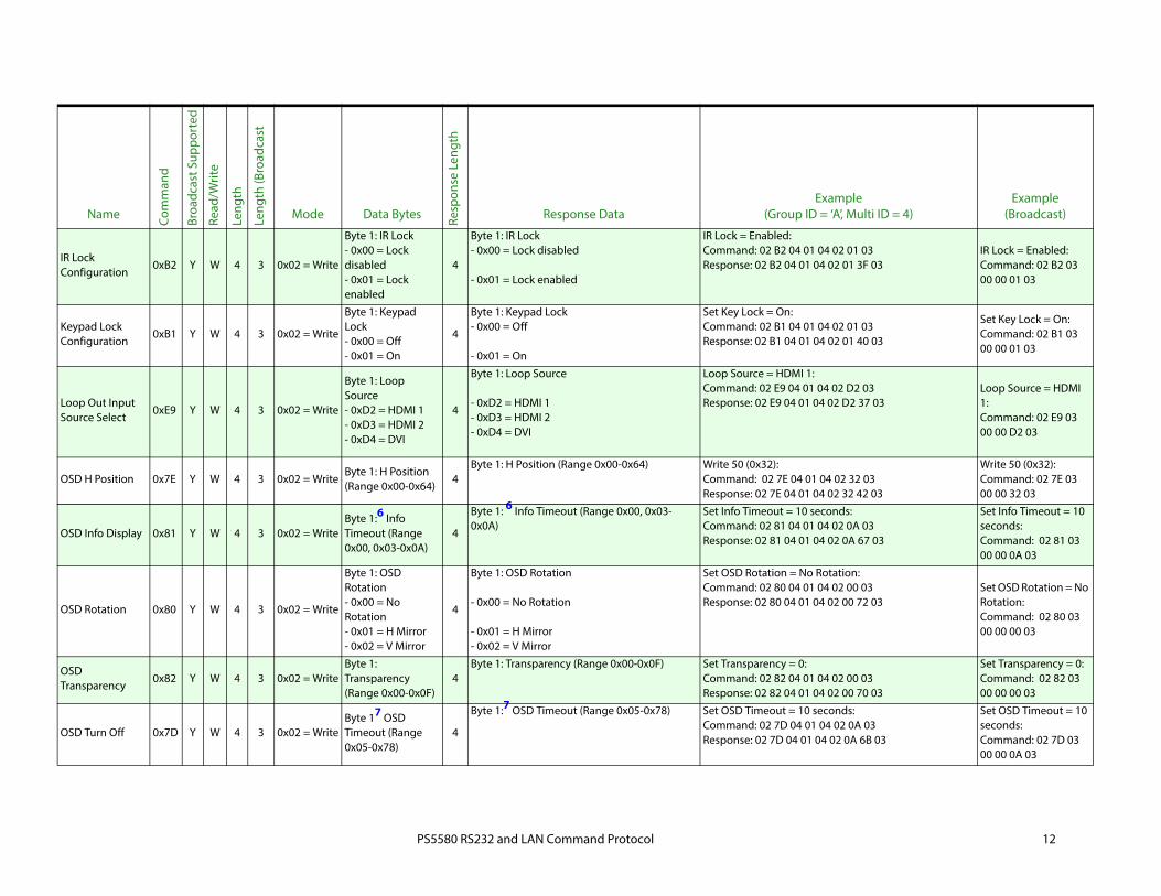
IR Lock Configuration
0xB2 Y W 4 3 0x02 = Write
Byte 1: IR Lock- 0x00 = Lock disabled- 0x01 = Lock enabled
4
Byte 1: IR Lock- 0x00 = Lock disabled
- 0x01 = Lock enabled
IR Lock = Enabled:Command: 02 B2 04 01 04 02 01 03Response: 02 B2 04 01 04 02 01 3F 03
IR Lock = Enabled:Command: 02 B2 03 00 00 01 03
Keypad Lock Configuration
0xB1 Y W 4 3 0x02 = Write
Byte 1: Keypad Lock- 0x00 = Off- 0x01 = On
4
Byte 1: Keypad Lock- 0x00 = Off
- 0x01 = On
Set Key Lock = On:Command: 02 B1 04 01 04 02 01 03Response: 02 B1 04 01 04 02 01 40 03
Set Key Lock = On:Command: 02 B1 03 00 00 01 03
Loop Out Input Source Select
0xE9 Y W 4 3 0x02 = Write
Byte 1: Loop Source- 0xD2 = HDMI 1- 0xD3 = HDMI 2- 0xD4 = DVI
4
Byte 1: Loop Source
- 0xD2 = HDMI 1- 0xD3 = HDMI 2- 0xD4 = DVI
Loop Source = HDMI 1:Command: 02 E9 04 01 04 02 D2 03Response: 02 E9 04 01 04 02 D2 37 03
Loop Source = HDMI 1:Command: 02 E9 03 00 00 D2 03
OSD H Position 0x7E Y W 4 3 0x02 = WriteByte 1: H Position(Range 0x00-0x64)
4Byte 1: H Position (Range 0x00-0x64) Write 50 (0x32):
Command: 02 7E 04 01 04 02 32 03Response: 02 7E 04 01 04 02 32 42 03
Write 50 (0x32):Command: 02 7E 03 00 00 32 03
OSD Info Display 0x81 Y W 4 3 0x02 = WriteByte 1:6 Info Timeout (Range 0x00, 0x03-0x0A)
4
Byte 1: 6 Info Timeout (Range 0x00, 0x03-0x0A)
Set Info Timeout = 10 seconds:Command: 02 81 04 01 04 02 0A 03Response: 02 81 04 01 04 02 0A 67 03
Set Info Timeout = 10 seconds:Command: 02 81 03 00 00 0A 03
OSD Rotation 0x80 Y W 4 3 0x02 = Write
Byte 1: OSD Rotation- 0x00 = No Rotation- 0x01 = H Mirror- 0x02 = V Mirror
4
Byte 1: OSD Rotation
- 0x00 = No Rotation
- 0x01 = H Mirror- 0x02 = V Mirror
Set OSD Rotation = No Rotation:Command: 02 80 04 01 04 02 00 03Response: 02 80 04 01 04 02 00 72 03
Set OSD Rotation = No Rotation:Command: 02 80 03 00 00 00 03
OSD Transparency
0x82 Y W 4 3 0x02 = WriteByte 1: Transparency (Range 0x00-0x0F)
4Byte 1: Transparency (Range 0x00-0x0F) Set Transparency = 0:
Command: 02 82 04 01 04 02 00 03Response: 02 82 04 01 04 02 00 70 03
Set Transparency = 0:Command: 02 82 03 00 00 00 03
OSD Turn Off 0x7D Y W 4 3 0x02 = WriteByte 17 OSD Timeout (Range 0x05-0x78)
4
Byte 1:7 OSD Timeout (Range 0x05-0x78) Set OSD Timeout = 10 seconds:Command: 02 7D 04 01 04 02 0A 03Response: 02 7D 04 01 04 02 0A 6B 03
Set OSD Timeout = 10 seconds:Command: 02 7D 03 00 00 0A 03
Name Com
man
d
Broa
dcas
t Sup
port
ed
Read
/Writ
e
Leng
th
Leng
th (B
road
cast
Mode Data Bytes Resp
onse
Len
gth
Response DataExample
(Group ID = ‘A’, Multi ID = 4)Example
(Broadcast)
PS5580 RS232 and LAN Command Protocol 13
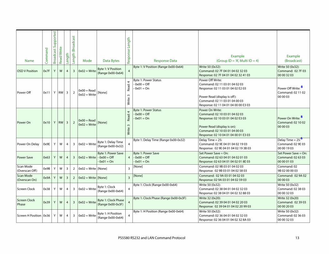
OSD V Position 0x7F Y W 4 3 0x02 = WriteByte 1: V Position(Range 0x00-0x64)
4Byte 1: V Position (Range 0x00-0x64) Write 50 (0x32):
Command: 02 7F 04 01 04 02 32 03Response: 02 7F 04 01 04 02 32 41 03
Write 50 (0x32):Command: 02 7F 03 00 00 32 03
Power Off 0x11 Y RW 3 20x00 = Read0x02 = Write
[None]
Writ
e: 3
Read
: 4
Byte 1: Power Status- 0x00 = Off- 0x01 = On
Power Off Write: Command: 02 11 03 01 04 02 03Response: 02 11 03 01 04 02 E2 03
Power Read (display is off ):Command: 02 11 03 01 04 00 03Response: 02 11 04 01 04 00 00 E3 03
Power Off Write: 8
Command: 02 11 02 00 00 03
Power On 0x10 Y RW 3 20x00 = Read0x02 = Write
[None]
Writ
e: 3
Read
: 4
Byte 1: Power Status- 0x00 = Off- 0x01 = On
Power On Write:Command: 02 10 03 01 04 02 03Response: 02 10 03 01 04 02 E3 03
Power Read (display is on):Command: 02 10 03 01 04 00 03Response: 02 10 04 01 04 00 01 E3 03
Power On Write: 8
Command: 02 10 02 00 00 03
Power On Delay 0x9E Y W 4 3 0x02 = WriteByte 1: Delay Time (Range 0x00-0x32)
4Byte 1: Delay Time (Range 0x00-0x32) Delay Time = 25:
Command: 02 9E 04 01 04 02 19 03Response: 02 9E 04 01 04 02 19 3B 03
Delay Time = 25:6 Command: 02 9E 03 00 00 19 03
Power Save 0x63 Y W 4 3 0x02 = WriteByte 1: Power Save- 0x00 = Off- 0x01 = On
4Byte 1: Power Save- 0x00 = Off- 0x01 = On
Set Power Save = On:Command: 02 63 04 01 04 02 01 03Response: 02 63 04 01 04 02 01 8E 03
Set Power Save = On:Command: 02 63 03 00 00 01 03
Scan Mode (Overscan Off )
0x9B Y W 3 2 0x02 = Write [None] 3[None] Command: 02 9B 03 01 04 02 03
Response: 02 9B 03 01 04 02 58 03Command: 029B 02 00 00 03
Scan Mode (Overscan On)
0x9A Y W 3 2 0x02 = Write [None] 3[None] Command: 02 9A 03 01 04 02 03
Response: 02 9A 03 01 04 02 59 03Command: 02 9A 02 00 00 03
Screen Clock 0x38 Y W 4 3 0x02 = WriteByte 1: Clock (Range 0x00-0x64)
4Byte 1: Clock (Range 0x00-0x64) Write 50 (0x32):
Command: 02 38 04 01 04 02 32 03Response: 02 38 04 01 04 02 32 88 03
Write 50 (0x32)Command: 02 38 03 00 00 32 03
Screen Clock Phase
0x39 Y W 4 3 0x02 = WriteByte 1: Clock Phase (Range 0x00-0x3F)
4Byte 1: Clock Phase (Range 0x00-0x3F) Write 32 (0x20):
Command: 02 39 04 01 04 02 20 03Response: 02 39 04 01 04 02 20 99 03
Write 32 (0x20)Command: 02 39 03 00 00 20 03
Screen H Position 0x36 Y W 4 3 0x02 = WriteByte 1: H Position (Range 0x00-0x64)
4Byte 1: H Position (Range 0x00-0x64) Write 50 (0x32):
Command: 02 36 04 01 04 02 32 03Response: 02 36 04 01 04 02 32 8A 03
Write 50 (0x32)Command: 02 36 03 00 00 32 03
Name Com
man
d
Broa
dcas
t Sup
port
ed
Read
/Writ
e
Leng
th
Leng
th (B
road
cast
Mode Data Bytes Resp
onse
Len
gth
Response DataExample
(Group ID = ‘A’, Multi ID = 4)Example
(Broadcast)

PS5580 RS232 and LAN Command Protocol 14
Screen V Position 0x37 Y W 4 3 0x02 = WriteByte 1: V Position (Range 0x00-0x64)
4Byte 1: V Position (Range 0x00-0x64) Write 50 (0x32):
Command: 02 37 04 01 04 02 32 03Response: 02 37 04 01 04 02 32 89 03
Write 50 (0x32)Command: 02 37 03 00 00 32 03
Serial Control (LAN Off )
0x71 Y W 3 2 0x02 = Write [None] 3[None] Command: 02 71 03 01 04 02 03
Response: 02 71 03 01 04 02 82 03Command: 02 71 02 00 00 03
Serial Control (LAN On)
0x70 Y W 3 2 0x02 = Write [None] 3[None] Command: 02 70 03 01 04 02 03
Response: 02 70 03 01 04 0283 03Command: 02 70 02 00 00 03
Sharpness 0x22 Y W 4 3 0x02 = WriteByte 1: Sharpness (Range 0x00-0x18)
4Byte 1: Sharpness (Range 0x00-0x18) Write 50 (0x32):
Command: 02 22 04 01 04 02 32 03Response: 02 22 04 01 04 02 32 9E 03
Write 50 (0x32)Command: 02 22 03 00 00 32 03
Test Pattern Mode
0xE7 Y W 4 3 0x02 = Write
Byte 1: Test Pattern- 0x00 = Disabled- 0x01 = White Pattern
4
Byte 1: Test Pattern- 0x00 = Disabled- 0x01 = White Pattern
Test Pattern = White Pattern:Command: 02 E7 04 01 04 02 01 03Response: 02 E7 04 01 04 02 01 0A 03
Test Pattern = White Pattern:Command: 02 E7 03 00 00 01 03
Tiling Menu Lock Configuration
0xB3 Y W 4 3 0x02 = Write
Byte 1: Tiling Lock- 0x00 = Lock disabled- 0x01 = Lock enabled
4
Byte 1: Tiling Lock- 0x00 = Lock disabled- 0x01 = Lock enabled
Tiling Lock = Enabled:Command: 02 B3 04 01 04 02 01 03Response: 02 B3 04 01 04 02 01 3E 03
Tiling Lock = Enabled:Command: 02 B3 03 00 00 01 03
Tint 0x24 Y W 4 3 0x02 = WriteByte 1: Tint (Range 0x4D-0xB1)
4Byte 1: Tint (Range 0x4D-0xB1) Write 0 (0x7F): 9
Command: 02 24 04 01 04 02 7F 03Response: 02 24 04 01 04 02 7F 4F 03
Write 0 (0x7F)Command: 02 24 03 00 00 7F 03
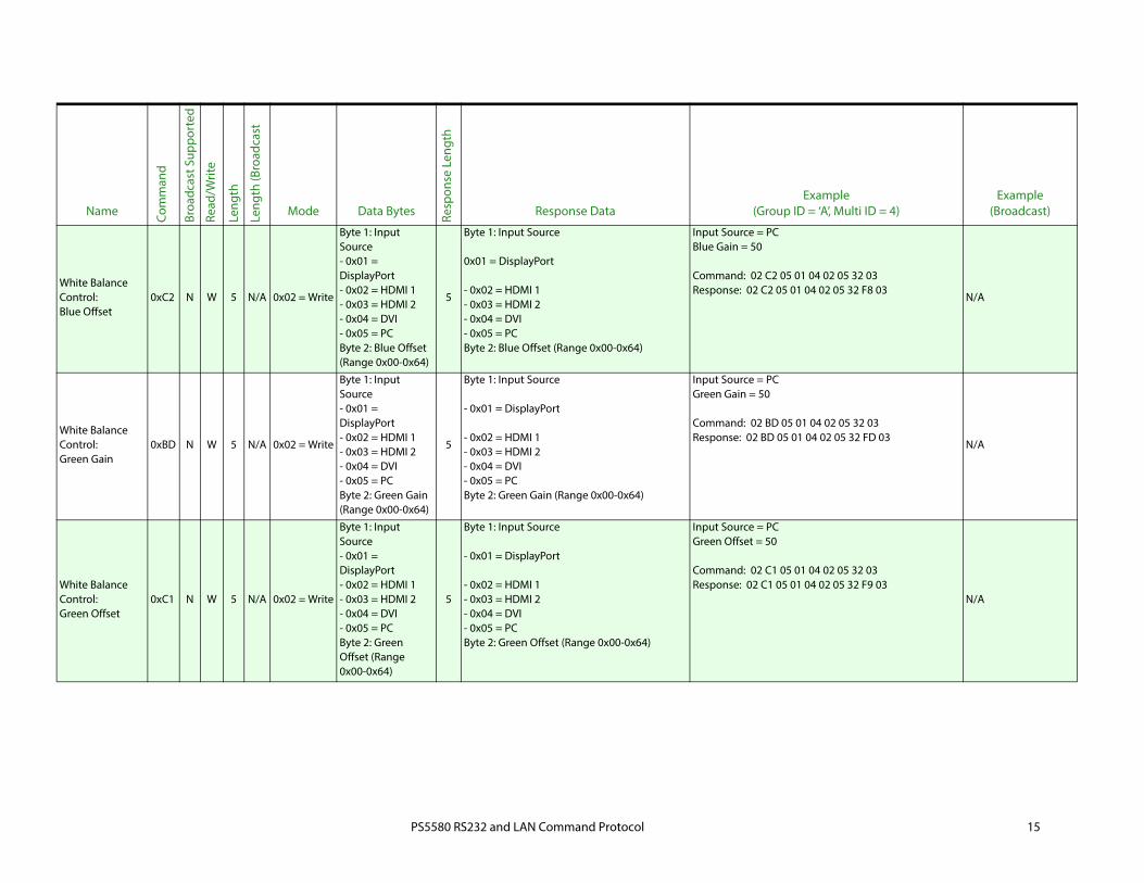
White Balance Control:Blue Gain
0xBE N W 5 N/A 0x02 = Write
Byte 1: Input Source- 0x01 = DisplayPort- 0x02 = HDMI 1- 0x03 = HDMI 2- 0x04 = DVI- 0x05 = PCByte 2: Blue Gain (Range 0x00-0x64)
5
Byte 1: Input Source
- 0x01 = DisplayPort
- 0x02 = HDMI 1- 0x03 = HDMI 2- 0x04 = DVI- 0x05 = PCByte 2: Blue Gain (Range 0x00-0x64)
Input Source = PCBlue Gain = 50
Command: 02 BE 05 01 04 02 05 32 03Response: 02 BE 05 01 04 02 05 32 FC 03
N/A
Name Com
man
d
Broa
dcas
t Sup
port
ed
Read
/Writ
e
Leng
th
Leng
th (B
road
cast
Mode Data Bytes Resp
onse
Len
gth
Response DataExample
(Group ID = ‘A’, Multi ID = 4)Example
(Broadcast)
PS5580 RS232 and LAN Command Protocol 15
White Balance Control:Blue Offset
0xC2 N W 5 N/A 0x02 = Write
Byte 1: Input Source- 0x01 = DisplayPort- 0x02 = HDMI 1- 0x03 = HDMI 2- 0x04 = DVI- 0x05 = PCByte 2: Blue Offset (Range 0x00-0x64)
5
Byte 1: Input Source
0x01 = DisplayPort
- 0x02 = HDMI 1- 0x03 = HDMI 2- 0x04 = DVI- 0x05 = PCByte 2: Blue Offset (Range 0x00-0x64)
Input Source = PCBlue Gain = 50
Command: 02 C2 05 01 04 02 05 32 03Response: 02 C2 05 01 04 02 05 32 F8 03
N/A
White Balance Control:Green Gain
0xBD N W 5 N/A 0x02 = Write
Byte 1: Input Source- 0x01 = DisplayPort- 0x02 = HDMI 1- 0x03 = HDMI 2- 0x04 = DVI- 0x05 = PCByte 2: Green Gain (Range 0x00-0x64)
5
Byte 1: Input Source
- 0x01 = DisplayPort
- 0x02 = HDMI 1- 0x03 = HDMI 2- 0x04 = DVI- 0x05 = PCByte 2: Green Gain (Range 0x00-0x64)
Input Source = PCGreen Gain = 50
Command: 02 BD 05 01 04 02 05 32 03Response: 02 BD 05 01 04 02 05 32 FD 03
N/A
White Balance Control:Green Offset
0xC1 N W 5 N/A 0x02 = Write
Byte 1: Input Source- 0x01 = DisplayPort- 0x02 = HDMI 1- 0x03 = HDMI 2- 0x04 = DVI- 0x05 = PCByte 2: Green Offset (Range 0x00-0x64)
5
Byte 1: Input Source
- 0x01 = DisplayPort
- 0x02 = HDMI 1- 0x03 = HDMI 2- 0x04 = DVI- 0x05 = PCByte 2: Green Offset (Range 0x00-0x64)
Input Source = PCGreen Offset = 50
Command: 02 C1 05 01 04 02 05 32 03Response: 02 C1 05 01 04 02 05 32 F9 03
N/A
Name Com
man
d
Broa
dcas
t Sup
port
ed
Read
/Writ
e
Leng
th
Leng
th (B
road
cast
Mode Data Bytes Resp
onse
Len
gth
Response DataExample
(Group ID = ‘A’, Multi ID = 4)Example
(Broadcast)
PS5580 RS232 and LAN Command Protocol 16
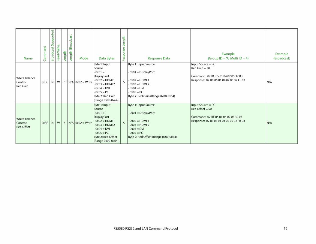
White Balance Control:Red Gain
0xBC N W 5 N/A 0x02 = Write
Byte 1: Input Source- 0x01 = DisplayPort- 0x02 = HDMI 1- 0x03 = HDMI 2- 0x04 = DVI- 0x05 = PCByte 2: Red Gain (Range 0x00-0x64)
5
Byte 1: Input Source
- 0x01 = DisplayPort
- 0x02 = HDMI 1- 0x03 = HDMI 2- 0x04 = DVI- 0x05 = PCByte 2: Red Gain (Range 0x00-0x64)
Input Source = PCRed Gain = 50
Command: 02 BC 05 01 04 02 05 32 03Response: 02 BC 05 01 04 02 05 32 FE 03
N/A
White Balance Control:Red Offset
0xBF N W 5 N/A 0x02 = Write
Byte 1: Input Source- 0x01 = DisplayPort- 0x02 = HDMI 1- 0x03 = HDMI 2- 0x04 = DVI- 0x05 = PCByte 2: Red Offset (Range 0x00-0x64)
5
Byte 1: Input Source
- 0x01 = DisplayPort
- 0x02 = HDMI 1- 0x03 = HDMI 2- 0x04 = DVI- 0x05 = PCByte 2: Red Offset (Range 0x00-0x64)
Input Source = PCRed Offset = 50
Command: 02 BF 05 01 04 02 05 32 03Response: 02 BF 05 01 04 02 05 32 FB 03
N/A
Name Com
man
d
Broa
dcas
t Sup
port
ed
Read
/Writ
e
Leng
th
Leng
th (B
road
cast
Mode Data Bytes Resp
onse
Len
gth
Response DataExample
(Group ID = ‘A’, Multi ID = 4)Example
(Broadcast)
PS5580 RS232 and LAN Command Protocol 17
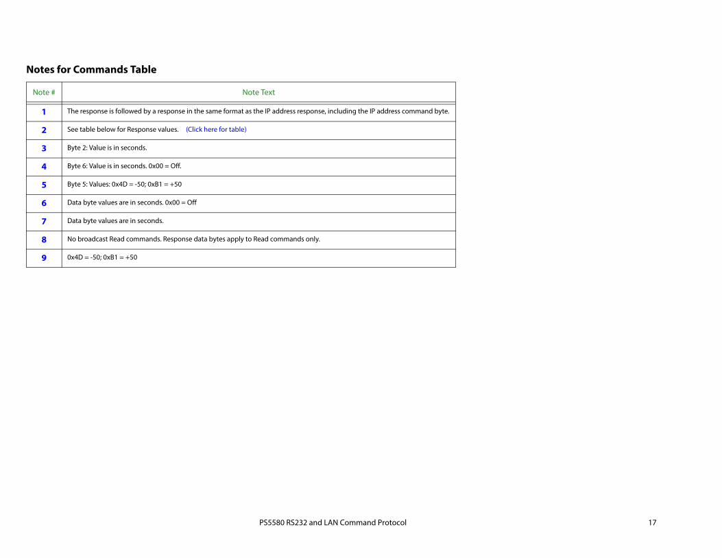
Notes for Commands Table
Note # Note Text
1 The response is followed by a response in the same format as the IP address response, including the IP address command byte.
2 See table below for Response values. (Click here for table)
3 Byte 2: Value is in seconds.
4 Byte 6: Value is in seconds. 0x00 = Off.
5 Byte 5: Values: 0x4D = -50; 0xB1 = +50
6 Data byte values are in seconds. 0x00 = Off
7 Data byte values are in seconds.
8 No broadcast Read commands. Response data bytes apply to Read commands only.
9 0x4D = -50; 0xB1 = +50
PS5580 RS232 and LAN Command Protocol 18
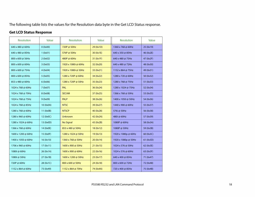
The following table lists the values for the Resolution data byte in the Get LCD Status response.
Get LCD Status Response
Resolution Value Resolution Value Resolution Value
640 x 480 @ 60Hz 0 (0x00) 720P @ 50Hz 29 (0x1D) 1360 x 768 @ 60Hz 25 (0x19)
640 x 480 @ 85Hz 1 (0x01) 576P @ 50Hz 30 (0x1E) 640 x 350 @ 85Hz 46 (0x2E)
800 x 600 @ 56Hz 2 (0x02) 480P @ 60Hz 31 (0x1F) 640 x 480 @ 75Hz 47 (0x2F)
800 x 600 @ 60Hz 3 (0x03) 1920 x 1080i @ 60Hz 32 (0x20) 640 x 480 @ 72Hz 48 (0x30)
800 x 600 @ 75Hz 4 (0x04) 1920 x 1080i @ 50Hz 33 (0x21) 1152 x 864 @ 75Hz 49 (0x31)
800 x 600 @ 85Hz 5 (0x05) 1280 x 720P @ 60Hz 34 (0x22) 1280 x 720 @ 60Hz 50 (0x32)
853 x 480 @ 60Hz 6 (0x06) 1280 x 720P @ 50Hz 35 (0x23) 1280 x 768 @ 75Hz 51 (0x33)
1024 x 768 @ 60Hz 7 (0x07) PAL 36 (0x24) 1280 x 1024 @ 75Hz 52 (0x34)
1024 x 768 @ 70Hz 8 (0x08) SECAM 37 (0x25) 1366 x 768 @ 50Hz 53 (0x35)
1024 x 768 @ 75Hz 9 (0x09) PALP 38 (0x26) 1400 x 1050 @ 50Hz 54 (0x36)
1024 x 768 @ 85Hz 10 (0x0A) NTSC 39 (0x27) 1440 x 900 @ 60Hz 55 (0x37)
1280 x 768 @ 60Hz 11 (0x0B) NTSCP 40 (0x28) 576i @ 50Hz 56 (0x38)
1280 x 960 @ 60Hz 12 (0x0C) Unknown 42 (0x2A) 480i @ 60Hz 57 (0x39)
1280 x 1024 @ 60Hz 13 (0x0D) No Signal 43 (0x2B) 1080P @ 60Hz 58 (0x3A)
1366 x 768 @ 60Hz 14 (0x0E) 853 x 480 @ 50Hz 18 (0x12) 1080P @ 50Hz 59 (0x3B)
1600 x 1200 @ 60Hz 15 (0x0F) 1280 x 1024 @ 50Hz 19 (0x13) 1920 x 1080p @ 60Hz 60 (0x3C)
1400 x 1050 @ 60Hz 16 (0x10) 1360 x 768 @ 50Hz 20 (0x14) 1920 x 1080p @ 50Hz 61 (0x3D)
1706 x 960 @ 60Hz 17 (0x11) 1600 x 900 @ 50Hz 21 (0x15) 1024 x 576 @ 50Hz 62 (0x3E)
1080i @ 60Hz 26 (0x1A) 1600 x 900 @ 60Hz 22 (0x16) 1024 x 576 @ 60Hz 63 (0x3F)
1080i @ 50Hz 27 (0x1B) 1600 x 1200 @ 50Hz 23 (0x17) 640 x 400 @ 85Hz 71 (0x47)
720P @ 60Hz 28 (0x1C) 800 x 600 @ 50Hz 24 (0x18) 800 x 600 @ 72Hz 72 (0x48)
1152 x 864 @ 60Hz 73 (0x49) 1152 x 864 @ 70Hz 74 (0x4A) 720 x 400 @ 85Hz 75 (0x4B)