provisioning services 6 - wordpress.com · 2012-02-16 · available from citrix edocs and/or from...
TRANSCRIPT
Provisioning Services 6.0
© 2011 Citrix Systems, Inc. All rights reserved. Terms of Use | Trademarks | Privacy Statement
Contents
Provisioning Services 6.0 9
Provisioning Services Product Overview 10
Provisioning Services Product Infrastructure 13
Provisioning Services Administrator Roles 23
Product Utilities 24
Provisioning Services and Resources 25
Getting the Bootstrap File 28
Selecting a vDisk Access Mode 31
Selecting the Write Cache Destination for Standard vDisk Images 33
Installation 36
Installation Wizards and Utilities 37
Overview: Installation and Configuration Tasks 39
Planning 40
Getting Product Licensing 53
Installing Provisioning Services Server Software 55
Configuring the Farm 57
Running the Configuration Wizard Silently 67
Installing Provisioning Services Console Software 69
Adding Additional Provisioning Servers 71
Managing Administrative Roles 72
Preparing a Master Target Device for Imaging 73
Creating vDisks Automatically 77
Using the Imaging Wizard to Create a New vDisk 78
Assigning vDisks to Target Devices 80
Uninstalling Product Software 82
Installing and Configuring Embedded Target Devices 83
System Requirements 84
Installing Embedded Target Devices 85
Un-installing an Embedded Target Device Package 86
2

Windows XP Embedded Build Overview 87
Setting Up Embedded Target Devices 91
Upgrading a Provisioning Services Farm 92
Upgrading the Database and Provisioning Servers 93
Upgrading vDisks by Re-imaging 95
Automated Upgrade of vDisks 96
Upgrading vDisks Manually 98
Image Back to Master Target Devices Hard Drive 99
Upgrading vDisks using Hyper-V 102
Managing Bootstrap Files and Boot Devices 104
Configuring the Bootstrap File From the Console 105
Using the Manage Boot Devices Utility 110
Administration 113
Using the Console 114
Starting the Console 115
Understanding the Console Window 116
Performing Tasks in the Console 119
Managing Farms 122
Configuring the Farm 123
Running the Configuration Wizard Silently 133
Farm Properties 135
Farm Tasks 139
Farm Connections 140
Managing Sites 141
Creating Sites 142
Site Properties 143
Managing Administrative Roles 146
Managing Farm Administrators 147
Managing Site Administrators 148
Managing Device Administrators 149
Managing Device Operators 150
Managing Stores 151
Store Administrative Privileges 153
Store Properties 154
Store Configuration and Management Tasks 157
Managing Provisioning Servers 159
Provisioning Servers in the Console 160
3
Provisioning Server Properties 161
Provisioning Server Tasks 167
Adding Additional Provisioning Servers 168
Copying and Pasting Provisioning Server Properties 169
Deleting a Provisioning Server 170
Starting, Stopping, or Restarting Provisioning Services 171
Showing Provisioning Server Connections 172
Balancing the Target Device Load on Provisioning Servers 173
Checking for Provisioning Server vDisk Access Updates 175
Configuring Provisioning Servers Manually 176
Disabling Write Cache to Improve Performance When Using StorageDevice Drives 178
Providing Provisioning Servers Access to Stores 179
Managing Target Devices 180
Getting the Bootstrap File 182
Configuring the Bootstrap File From the Console 185
Using the Manage Boot Devices Utility 190
Configuring the BIOS Embedded Bootstrap 193
Target Device Tasks 196
Preparing a Master Target Device for Imaging 197
Adding Target Devices to the Database 201
Using the Auto-Add Wizard 202
Assigning vDisks to Target Devices 204
Set the Target Device as the Template for this Collection 206
Copy and Paste Target Device Properties 207
Booting Target Devices 208
Checking a Target Device's Status from the Console 209
Sending Messages to Target Devices 210
Disabling a Target Device 211
Deleting Target Devices 212
Shutting Down Target Devices 213
Restarting Target Devices 214
Moving Target Devices Between Collections 215
Using the Status Tray on a Target Device 216
Managing Target Device Personality 220
Target Device Properties 224
Managing vDisks 229
Creating vDisks 231
4
VHD Chain of Differencing Disks 234
Creating vDisks Automatically 236
Using the Imaging Wizard to Create a New vDisk 237
Creating vDisk Files Manually 239
Creating Common Images for XenServer VMs and Physical Devices 243
Creating Common Images for use with Both XenServer VMs andPhysical Devices 244
Creating a Common Image for use with Multiple Physical DeviceTypes 247
Deploying vDisks 251
Configuring vDisks for Deployment 252
Selecting a vDisk Access Mode 253
Configuring the vDisk Access Mode 255
Selecting the Write Cache Destination for Standard vDiskImages 256
Configuring for Microsoft Volume Licensing 259
Configuring Microsoft KMS Volume Licensing 260
Configuring Microsoft MAK Volume Licensing 263
Configuring a vDisk for Microsoft Volume Licensing 266
Configuring vDisks for Active Directory Management 267
Active Directory Integration Prerequistes 268
Managing Domain Passwords 269
Enabling Domain Management 271
Managing Domain Computer Accounts 272
Managing Load Balancing Across Servers 275
Managing Printers 277
Installing Printers on a vDisk 278
Enabling or Disabling Printers on a vDisk 279
Methods for Enabling Printers on a vDisk 281
Enabling the Printer Management Feature 284
Support for Replicated vDisk Storage 285
Common vDisk Maintenance Tasks 288
Exporting and Importing vDisks 289
Releasing vDisk Locks 291
Copying and Pasting vDisk Properties 292
Backing Up a vDisk 293
Viewing vDisk Usage 294
Deleting Cache on a Difference Disk 295
vDisk Properties 296
5
Assigning vDisks and Versions to Target Devices 300
Accessing a vDisk Version 301
Assigning vDisks to Target Devices 303
Unassigning vDisks from Target Devices 305
vDisk Versioning Dialog 306
Updating vDisks 309
VHD Chain of Differencing Disks 311
Manually Updating a vDisk Image 313
Automating vDisk Updates 314
Enabling Automatic vDisk Updates 317
Configuring Virtual Host Connections for Automated vDiskUpdates 318
Virtual Host Connection Properties 320
Creating and Configuring ESD Update VMs 322
Configuring Managed vDisks for Automated Updates 327
Managed vDisk Dialog 328
Creating and Managing Tasks 329
Using Windows Task Scheduler to Create vDisk Update TaskScripts 331
vDisk Update Task Properties 334
Updating vDisks on Demand 337
Update Device Properties 338
Merging VHD Differencing Disks 341
Promoting Updated Versions 345
Retiring or Deleting vDisks 346
Managing Device Collections 347
Device Collection Properties 348
Device Collection Management Tasks 351
Creating a Device Collection 352
Importing Target Devices into a Collection 353
Deleting a Collection 354
Refreshing a Collection in the Console 355
Booting Target Devices within a Collection 356
Restarting Target Devices within a Collection 357
Shutdown Target Devices within a Collection 358
Sending Messages to Target Devices within a Collection 359
Moving Collections within a Site 360
Configuring Microsoft KMS Volume Licensing 361
6
Configuring Microsoft MAK Volume Licensing 364
Managing Views 367
View Properties 368
Managing Views in the Console 369
Managing for Highly Available Implementations 373
Offline Database Support 374
Database Mirroring 376
Provisioning Server Failover 378
Testing Target Device Failover 380
Configuring for High Availability with Shared Storage 381
Configuring the Boot File for High Availability 385
Configuring vDisks for Active Directory Management 388
Active Directory Integration Prerequistes 389
Managing Domain Passwords 390
Enabling Domain Management 392
Managing Domain Computer Accounts 393
Managing Network Components 396
Preparing Network Switches 397
Using UNC Names 398
Reducing Network Utilization 400
Managing Roaming User Profiles 405
Booting Through a Router 408
Updating NIC Drivers 410
Managing and Accessing a LUN Without Using a Network Share 411
Managing Printers 416
Installing Printers on a vDisk 417
Enabling or Disabling Printers on a vDisk 418
Methods for Enabling Printers on a vDisk 420
Enabling the Printer Management Feature 423
Updating vDisks on Physical Devices 424
Using the Streamed VM Setup Wizard 428
Using the XenDesktop Setup Wizard 431
Logging 436
Configuring Provisioning Server Log Properties 437
Configuring Target Device Log Properties 439
Log Files and Content 440
Auditing 442
7

Enabling Auditing Information 444
Accessing Auditing Information 445
Archiving Audit Trail Information 449
Managing Multiple Network Interface Cards 450
Requirements and Considerations for Manufacturer's NIC Teaming 451
Requirements and Considerations for Provisioning Services NIC Failover 452
Glossary 453
8
9
Provisioning Services 6.0
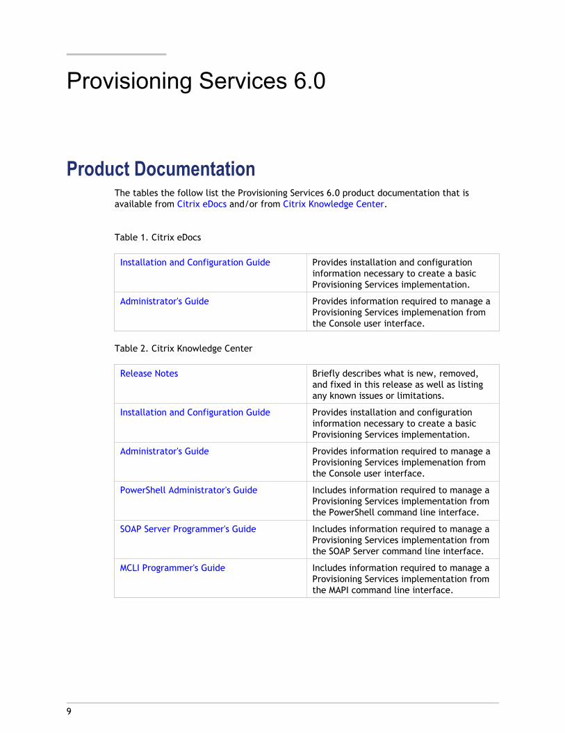
Product DocumentationThe tables the follow list the Provisioning Services 6.0 product documentation that isavailable from Citrix eDocs and/or from Citrix Knowledge Center.
Table 1. Citrix eDocs
Installation and Configuration Guide Provides installation and configurationinformation necessary to create a basicProvisioning Services implementation.
Administrator's Guide Provides information required to manage aProvisioning Services implemenation fromthe Console user interface.
Table 2. Citrix Knowledge Center
Release Notes Briefly describes what is new, removed,and fixed in this release as well as listingany known issues or limitations.
Installation and Configuration Guide Provides installation and configurationinformation necessary to create a basicProvisioning Services implementation.
Administrator's Guide Provides information required to manage aProvisioning Services implemenation fromthe Console user interface.
PowerShell Administrator's Guide Includes information required to manage aProvisioning Services implementation fromthe PowerShell command line interface.
SOAP Server Programmer's Guide Includes information required to manage aProvisioning Services implementation fromthe SOAP Server command line interface.
MCLI Programmer's Guide Includes information required to manage aProvisioning Services implementation fromthe MAPI command line interface.
10
Provisioning Services Product Overview
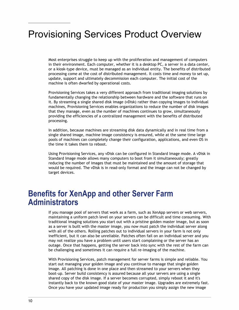
Most enterprises struggle to keep up with the proliferation and management of computersin their environment. Each computer, whether it is a desktop PC, a server in a data center,or a kiosk-type device, must be managed as an individual entity. The benefits of distributedprocessing come at the cost of distributed management. It costs time and money to set up,update, support and ultimately decommission each computer. The initial cost of themachine is often dwarfed by operational costs.
Provisioning Services takes a very different approach from traditional imaging solutions byfundamentally changing the relationship between hardware and the software that runs onit. By streaming a single shared disk image (vDisk) rather than copying images to individualmachines, Provisioning Services enables organizations to reduce the number of disk imagesthat they manage, even as the number of machines continues to grow, simultaneouslyproviding the efficiencies of a centralized management with the benefits of distributedprocessing.
In addition, because machines are streaming disk data dynamically and in real time from asingle shared image, machine image consistency is ensured, while at the same time largepools of machines can completely change their configuration, applications, and even OS inthe time it takes them to reboot.
Using Provisioning Services, any vDisk can be configured in Standard Image mode. A vDisk inStandard Image mode allows many computers to boot from it simultaneously; greatlyreducing the number of images that must be maintained and the amount of storage thatwould be required. The vDisk is in read-only format and the image can not be changed bytarget devices.
Benefits for XenApp and other Server FarmAdministrators
If you manage pool of servers that work as a farm, such as XenApp servers or web servers,maintaining a uniform patch level on your servers can be difficult and time consuming. Withtraditional imaging solutions you start out with a pristine golden master image, but as soonas a server is built with the master image, you now must patch the individual server alongwith all of the others. Rolling patches out to individual servers in your farm is not onlyinefficient, but it can also be unreliable. Patches often fail on an individual server and youmay not realize you have a problem until users start complaining or the server has anoutage. Once that happens, getting the server back into sync with the rest of the farm canbe challenging and sometimes it can require a full re-imaging of the machine.
With Provisioning Services, patch management for server farms is simple and reliable. Youstart out managing your golden image and you continue to manage that single goldenimage. All patching is done in one place and then streamed to your servers when theyboot-up. Server build consistency is assured because all your servers are using a singleshared copy of the disk image. If a server becomes corrupted, simply reboot it and it'sinstantly back to the known good state of your master image. Upgrades are extremely fast.Once you have your updated image ready for production you simply assign the new image
version to the servers and reboot them. In the time it takes them to reboot you can deploythe new image to any number of servers. Just as importantly, roll-backs can be done in thesame manner so problems with new images will not take your servers or your users out ofcommission for an extended period of time.
Benefits for Desktop AdministratorsAs part of XenDesktop, desktop administrators have the ability to use Provisioning Services'streaming technology to simplify, consolidate, and reduce the costs of both physical andvirtual desktop delivery. Many organizations are beginning to explore desktop virtualization.While virtualization addresses many of the consolidation and simplified management needsof IT, deploying it also requires deployment of supporting infrastructure. WithoutProvisioning Services, storage costs can put desktop virtualization out of the budget. WithProvisioning Services, IT can reduce the amount of storage required for VDI by as much as90%. At the same time the ability to manage a single image rather than hundreds orthousands of desktops significantly reduces the cost, effort, and complexity for desktopadministration.
Different types of workers across the enterprise need different types of desktops. Somerequire simplicity and standardization, while others require high performance andpersonalization. XenDesktop can meet these requirements in a single solution usingFlexCast™ delivery technology. With FlexCast™, IT can deliver every type of virtual desktop- each specifically tailored to meet the performance, security and flexibility requirementsof each individual user.
Not all desktops applications can be supported by virtual desktops. For these scenarios, ITcan still reap the benefits of consolidation and single image management. Desktop imagesare stored and managed centrally in the datacenter and streamed out to physical desktopson demand. This model works particularly well for standardized desktops such as those inlab and training environments, call centers, and "thin client" devices used to access virtualdesktops.
Provisioning Services SolutionProvisioning Services streaming technology allows computers to be provisioned andre-provisioned in real-time from a single shared-disk image. In doing so, administrators cancompletely eliminate the need to manage and patch individual systems. Instead, all imagemanagement is done on the master image. The local hard-disk drive of each system may beused for runtime data caching or, in some scenarios, removed from the system entirely,which reduces power usage, system failure rates, and security risks.
The Provisioning Services solution’s infrastructure is based on software-streamingtechnology. After installing and configuring Provisioning Services components, a vDisk iscreated from a device’s hard drive by taking a snapshot of the OS and application image,and then storing that image as a vDisk file on the network. A device that is used during thisprocess is referred to as a Master target device. The devices that use those vDisks arecalled target devices.
vDisks can exist on a Provisioning Server, file share, or in larger deployments, on a storagesystem that the Provisioning Server can communicate with (iSCSI, SAN, NAS, and CIFS).vDisks can be assigned to a single target device as Private Image Mode, or to multiple target
Provisioning Services Product Overview
11
devices as Standard Image Mode.
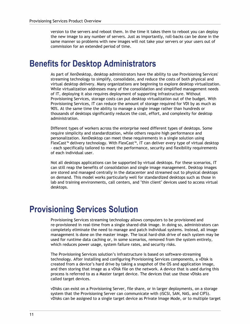
When a target device is turned on, it is set to boot from the network and to communicatewith a Provisioning Server. Unlike thin-client technology, processing takes place on thetarget device (refer to Step 1 in the illustration that follows).
The target device downloads the boot file from a Provisioning Server (refer to Step 2), andthen the target device boots. Based on the device boot configuration settings, theappropriate vDisk is located, then mounted on the Provisioning Server (refer to step 3). Thesoftware on that vDisk is streamed to the target device as needed. To the target device, itappears like a regular hard drive to the system.
Instead of immediately pulling all the vDisk contents down to the target device (as donewith traditional or imaging deployment solutions), the data is brought across the network inreal-time, as needed. This approach allows a target device to get a completely newoperating system and set of software in the time it takes to reboot, without requiring a visitto a workstation. This approach dramatically decreases the amount of network bandwidthrequired by traditional disk imaging tools; making it possible to support a larger number oftarget devices on your network without impacting overall network performance.
Product LicensesProduct licenses are issued based on the product edition that you choose. For Citrix productlicensing documentation, open the Citrix Knowledge Center, then select Licensing under theKnowledge Resources section. For licensing time out conditions, refer to Getting ProductLicensing.
Provisioning Services Product Overview
12
13
Provisioning Services ProductInfrastructure
The Provisioning Service's infrastructure design directly relates to administrative roleswithin a Provisioning Services farm. The Provisioning Services administrator role determineswhich components that administrator can manage or view in the Console (for details, referto 'Managing Administrator Roles' in the Provisioning Services Administrator's Guide).
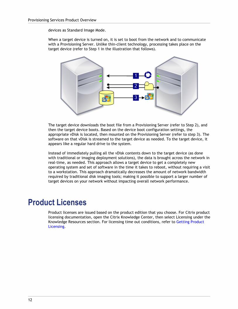
There are several components that make up a Provisioning Services farm. The graphic thatfollows provides a high-level view of a basic Provisioning Services infrastructure andillustrates how Provisioning Services components might appear within that implementation.
The sections that follow provide a brief introduction to Provisioning Services components.For details on managing each component, refer to the appropriate chapter in theProvisioning Services Administrator's Guide.
License ServerThe product license server is installed within the shared infrastructure or an existing Citrixlicence server can be selected.
Note: The license server is selected when the Configuration Wizard is run on aProvisioning Server. All Provisioning Servers within the farm must be able to communicatewith the license server.
Provisioning Services DatabaseThe database stores all system configuration settings that exist within a farm. Only onedatabase can exist within a farm and all Provisioning Servers in that farm must be able tocommunicate with that database. You may choose to leverage an existing SQL Serverdatabase or install SQL Server Express, which is free and available from Microsoft.
Note: The database server is selected when the Configuration Wizard is run on aProvisioning Server.
ConsoleThe Console is a utility that is used to manage your Provisioning Services implementation.After logging on to the Console, you select the farm that you want to connect to. Youradministrative role determines what you can view in the Console and manage in the farm(for details, refer to (for more details, refer to 'Managing Consoles' in the ProvisioningServices Administrator's Guide.
Note: The Console is installed as a separate component and is available from the productinstallation media. The Provisioning Services Console is an MMC (Microsoft ManagementConsole) snap-in. MMC specific console features are not described in this document. Referto Microsoft’s MMC documentation for detailed information.
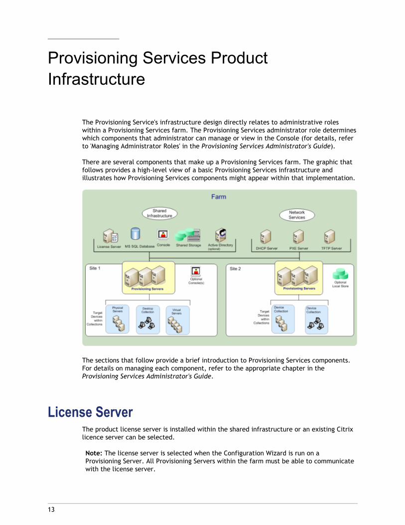
When the Farm node is expanded at the highest level, the Provisioning Services Consolewindow displays as follows:
Action Menu
Provisioning Services Product Infrastructure
14
The Action menu displays Provisioning Services tasks that can be performed on an objectthat is highlighted in the Console. The same tasks are available when you right-click on theobject in the Console.
Tasks are object specific and can only be performed if the user has the appropriate roleassigned (role-based administration). Your role determines what displays in the Console.For example, if you are a farm administrator, you can perform all tasks and see all objectsin the farm. Device administrators can only perform device-collection management tasks oncollections to which they have privileges. Administrator roles are described later in thischapter.
Console Tree and Details Pane
To view information about an object in the Details pane, click on the object or folder in theTree pane. The Details pane provides information such as the objects name and adescription of that object.
Properties Menus
To view or change an object’s properties, right-click on the object, then select theProperties menu option. You can also highlight the object in the Console window, thenselect Properties from the Action menu options. The Properties dialog displays propertysettings in tabular format.
Network ServicesNetwork services include a DHCP service, Preboot Execution Environment (PXE) service, anda TFTP service. These service options can be used during the boot process to retrieve IPaddresses, and locate then download the boot program from the Provisioning Server to thetarget device. Alternative boot options are also available (for network service details, referto 'Managing Bootstrap Files and Boot Devices' in the Provisioning Services Administrator'sGuide).
Note: Network services can be installed with the product installation (optional), and thenconfigured when the Configuration Wizard is run. Existing network services within yourinfrastructure also be leveraged.
FarmsA farm represents the top level of a Provisioning Services infrastructure. The farm iscreated when the Configuration Wizard is run on the first Provisioning Server that will beadded to that farm. Farms provide a farm administrator with a method for managing allcomponents within the farm, such as:
● Product licensing
● Farm properties
● Administrative roles
● Active Directory configurations
Provisioning Services Product Infrastructure
15
● Provisioning Servers
● vDisk images
● Target devices
● Target device collections
● Sites
● Stores
● Views
Note: All sites within a farm share that farm’s Microsoft SQL database. The Console doesnot need to be directly associated with the farm because remote administration issupported on any Console that can communicate with that farm’s network.
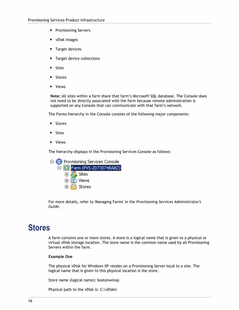
The Farms hierarchy in the Console consists of the following major components:
● Stores
● Sites
● Views
The hierarchy displays in the Provisioning Services Console as follows:
For more details, refer to 'Managing Farms' in the Provisioning Services Administrator'sGuide.
StoresA farm contains one or more stores. A store is a logical name that is given to a physical orvirtual vDisk storage location. The store name is the common name used by all ProvisioningServers within the farm.
Example One
The physical vDisk for Windows XP resides on a Provisioning Server local to a site. Thelogical name that is given to this physical location is the store.
Store name (logical name): bostonwinxp
Physical path to the vDisk is: C:\vDisks\
Provisioning Services Product Infrastructure
16
Example Two
The physical vDisk for Windows XP resides on a network share (FinanceVdisks) at the farmlevel.
Store name (logical name): financevdisks
Physical path to the vDisk for all Provisioning Servers in the farm is:\\financeserver\financevdisks\
Access or visibility to a store depends on the users administrative privileges:
● Farm administrators have full access to all stores within the farm.
● Site administrators have access to only those stores owned by the site. They can deletestores owned by the site but they can not modify store properties or add vDisks to thestore.
● Device administrators and device operators have read-only access and can not viewstore information. Site Administrators may also have read-only access if that storeexists at the farm level, or if that store belongs to another site.
Examples of store tasks that a Farm administrator is able to perform includes:
● Configuring store properties
● Creating or importing new vDisks
● Adding new vDisk Versions to the store
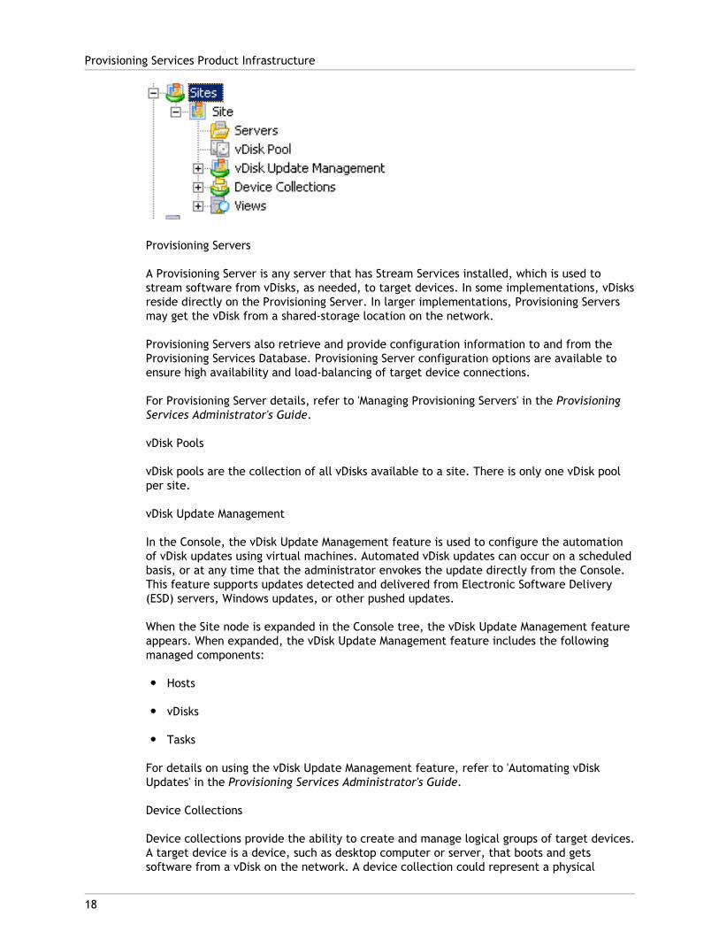
SitesOne or more sites can exist within a Farm. The first site is created with the ConfigurationWizard is run on the first Provisioning Server in the farm. A site provides both a siteadministrator and farm administrator, with a method of representing and managingcomponents within a site, which includes:
● Servers
● vDisk Pools
● vDisk Update Management components
● Device Collections
● Views
Sites are represented in the Console as follows:
Provisioning Services Product Infrastructure
17
Provisioning Servers
A Provisioning Server is any server that has Stream Services installed, which is used tostream software from vDisks, as needed, to target devices. In some implementations, vDisksreside directly on the Provisioning Server. In larger implementations, Provisioning Serversmay get the vDisk from a shared-storage location on the network.
Provisioning Servers also retrieve and provide configuration information to and from theProvisioning Services Database. Provisioning Server configuration options are available toensure high availability and load-balancing of target device connections.
For Provisioning Server details, refer to 'Managing Provisioning Servers' in the ProvisioningServices Administrator's Guide.
vDisk Pools
vDisk pools are the collection of all vDisks available to a site. There is only one vDisk poolper site.
vDisk Update Management
In the Console, the vDisk Update Management feature is used to configure the automationof vDisk updates using virtual machines. Automated vDisk updates can occur on a scheduledbasis, or at any time that the administrator envokes the update directly from the Console.This feature supports updates detected and delivered from Electronic Software Delivery(ESD) servers, Windows updates, or other pushed updates.
When the Site node is expanded in the Console tree, the vDisk Update Management featureappears. When expanded, the vDisk Update Management feature includes the followingmanaged components:
● Hosts
● vDisks
● Tasks
For details on using the vDisk Update Management feature, refer to 'Automating vDiskUpdates' in the Provisioning Services Administrator's Guide.
Device Collections
Device collections provide the ability to create and manage logical groups of target devices.A target device is a device, such as desktop computer or server, that boots and getssoftware from a vDisk on the network. A device collection could represent a physical
Provisioning Services Product Infrastructure
18
location, a subnet range, or a logical grouping of target devices. Creating device collectionssimplifies device management by performing actions at the collection level rather than atthe target-device level.
Note: A target device can only be a member of one device collection.
Device collections are created and managed by farm administrators, site administratorsthat have security privileges to that site, or device administrators that have securityprivileges to that collection. Device administrators can not modify the collection itself; onlythe devices within it. Device operators can only perform tasks on device collections thatthey are assigned to.
vDisks
vDisks exist as disk image files on a Provisioning Server or on a shared storage device. AvDisk consists of a VHD base image file, any associated properties files (.pvp), and ifapplicable, a chain of referenced VHD differencing disks (.avhd).
vDisks are assigned to target devices. Target devices boot from and stream software froman assigned vDisk image.
vDisk Modes
vDisk images are configured to be in Private Image mode (for use by a single device,read/write) or Standard Image mode (for use by multiple devices, read-only with variouscaching options).
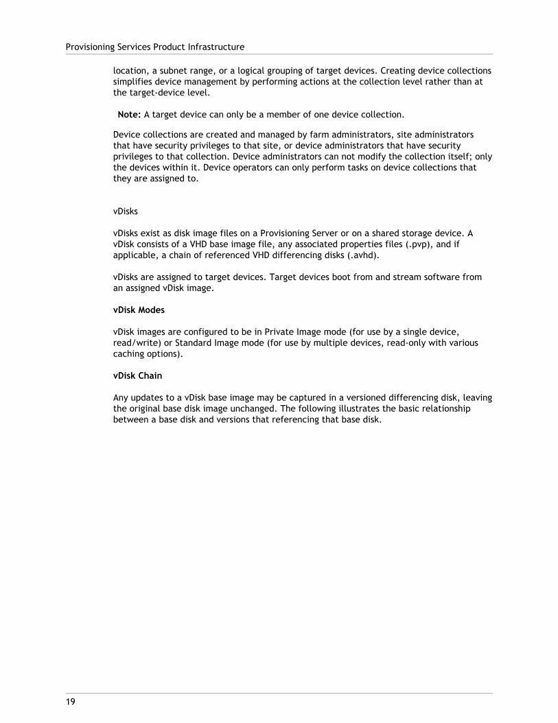
vDisk Chain
Any updates to a vDisk base image may be captured in a versioned differencing disk, leavingthe original base disk image unchanged. The following illustrates the basic relationshipbetween a base disk and versions that referencing that base disk.
Provisioning Services Product Infrastructure
19
Each time a vDisk is to be updated, a new version of the VHD differencing disk can becreated and the file name is numerically incremented, as captured in the table thatfollows.
VHD Filename
Base Image win7dev.avhd
Version 1 win7dev.1.avhd
Version 2 win7dev.2.avhd
... ...
Version N win7dev.N.avhdBooting a vDisk
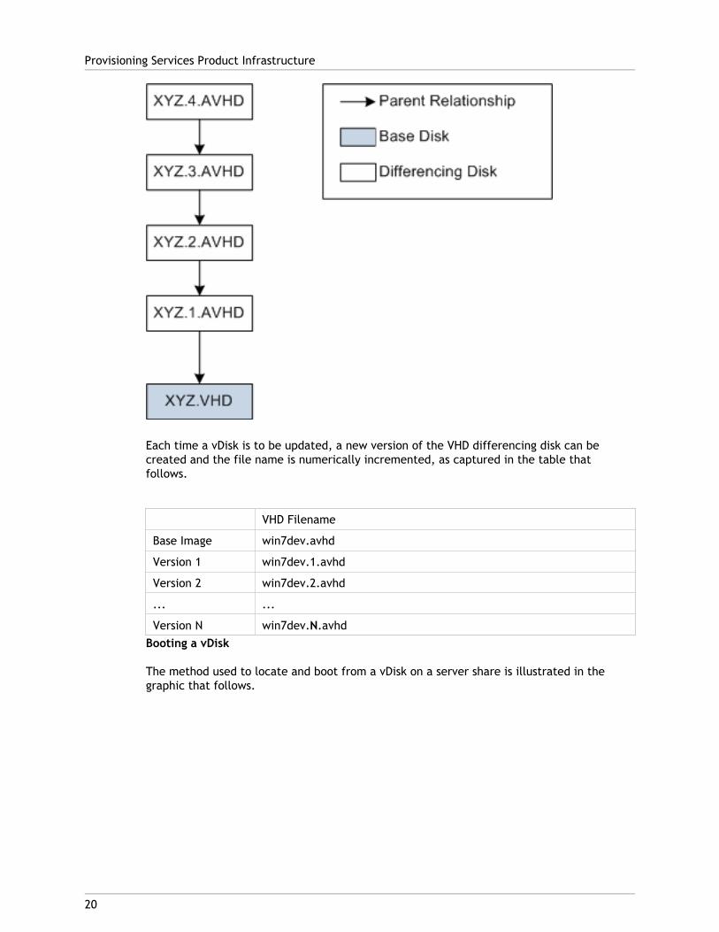
The method used to locate and boot from a vDisk on a server share is illustrated in thegraphic that follows.
Provisioning Services Product Infrastructure
20
1. The target device begins the boot process by communicating with a Provisioning Serverand acquiring a license.
2. The Provisioning Server checks the vDisk pool for vDisk information, which includesidentifying the Provisioning Server(s) that can provide the vDisk to the target deviceand the path information that server should use to get to the vDisk. In this example, thevDisk shows that only one Provisioning Server in this site can provide the target devicewith the vDisk and that the vDisk physically resides on the Finance Server (sharedstorage at the farm level).
3. The Provisioning Server locates the vDisk on Finance Server, then streams that vDisk, ondemand, to the target device.
ViewsViews provide a method that allows you to quickly manage a group of target devices. Viewsare typically created according to business needs. For example, a view can represent aphysical location, such as a building or user type. Unlike device collections, a target devicecan be a member of any number of views.
Provisioning Services Product Infrastructure
21
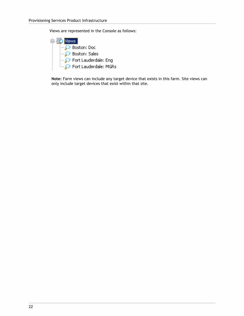
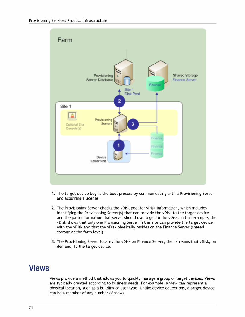
Views are represented in the Console as follows:
Note: Farm views can include any target device that exists in this farm. Site views canonly include target devices that exist within that site.
Provisioning Services Product Infrastructure
22
23
Provisioning Services Administrator Roles
The ability to view and manage objects within a Provisioning Services implementation isdetermined by the administrative role assigned to a group of users. Provisioning Servicesmakes use of groups that already exist within the network (Windows or Active DirectoryGroups).
All members within a group share the same administrative privileges within a farm. Anadministrator may have multiple roles if they belong to more than one group.
Groups are managed at the farm level through the Console’s Farm Properties dialog.
The following roles exist within a Provisioning Services farm:
● Farm Administrator – Farm administrators can view and manage all objects within afarm. Farm administrators can also create new sites and manage role membershipsthroughout the entire farm.
● Site Administrator – Site administrators have full management access to the all objectswithin a site. For example, a site administrator can manage Provisioning Servers, siteproperties, target devices, device collections, vDisks, vDisk pools, and local vDiskstores. A site administrator can also manage device administrator and device operatormemberships.
● Device Administrator – Device administrators can perform all device-collectionmanagement tasks on collections to which they have privileges, including; view vDiskproperties (read-only), assign or remove vDisks from a device, boot or shut down targetdevices, edit device properties, and send messages to target devices within a devicecollection to which they have privileges.
● Device Operator – Device operators can view target device properties (read-only), bootor shut down target devices, and send messages to target devices within a devicecollection to which they have privileges.
For details on administrator roles, refer to 'Managing Administrators' in the Administrator'sGuide.
24
Product Utilities
In addition, Provisioning Services includes several tools for use when configuring andmanaging a Provisioning Services deployment. After installing Provisioning Servicessoftware, the following tools become available:
● Installation Wizard – Use this wizard to install Provisioning Services components tocreate a Provisioning Servers and Master target devices.
● Configuration Wizard – Use this wizard to configure Provisioning-Server components,including network services, and database permissions. This wizard is installed duringthe Provisioning Services installation process.
● Imaging Wizard – On the master target device, run the Provisioning Services ImagingWizard to create a vDisk file in the Provisioning Services database and then image tothat file without having to physically go to a Provisioning Server. This utility is installedduring the target device installation process.
● Virtual Disk Status Tray – Use this target device utility to get target-device connectionstatus and streaming statistical information. This utility is installed during theProvisioning Services target device installation process.
● XenDesktop Setup Wizard – Creates virtual machines (VMs), associates target devices tothose VMs, assigns a shared vDisk to each target device, then adds all virtual desktopsto the XenDesktop catalog.
● Streamed VM Setup Wizard – Creates VMs, associates target devices to those VMs, thenassigns a shared vDisk to each target device. For use with vDisk update management.
● Virtual Host Connection Wizard – Adds a new virtual host connections to the vDiskUpdate Manager.
● Managed vDisk Setup Wizard – Adds new managed vDisks to the vDisk Update Manager.
● Update Task Wizard – Configures a new update task for use with vDisk Update Manager.
● Boot Device Manager – Use this utility to configure a boot device, such as a USB orCD-ROM, which then receives the boot program from the Provisioning Services.
● Upgrade Utilities – There are several upgrade methods available. The method you selectdepends on your network requirements.
● Programming Utilities – Provisioning Services provides programmers with a managementapplication programming utility and a command line utility. These utilities can beaccessed by all users. However, users can only use those commands associated withtheir administrator privileges. For example, a Device Operator is able to use this utilityto get a list of all target devices that they have access to.
25
Provisioning Services and Resources
The following services and resources are available to support Provisioning Services.
● Provisioning Services Documentation
● Getting Service and Support
● Getting the Subscription Advantage
● Locating the Citrix Developer Network
● Participating in Citrix Education and Training
Provisioning Services DocumentationThe following identifies the documentation that is available to support ProvisioningServices. All supporting documentation assumes that Provisioning Services administratorsare knowledgeable about networking components and administration, and that deviceoperators are familiar with networking concepts.
The majority of product documentation is provided as Adobe Portable Document Format(PDF) files. To view, search, and print PDF documentation, you need to have Adobe Reader5.0.5 with Search, or a more recent version. You can download these products for free fromAdobe System’s Web site at http://www.adobe.com/
Most PDF product documentation, including knowledge-based topics and white papers, areaccessible from the Citrix Knowledge Center, http://support.citrix.com/ or from CitrixeDocs at http://support.citrix.com/proddocs/index.jsp.
Citrix Product Licensing Documentation
For Citrix product licensing documentation, refer to Licensing Your Product under theTechnologies section on Citrix eDocs (http://support.citrix.com/proddocs/index.jsp).
Release Notes
This document contains important product information and is intended to be read first.Contents include information on new product features, enhancements, and known productissues as well as late additions that were not included in the other product documentation.
The release notes are accessible from:
● Citrix Knowledge Center: http://support.citrix.com/
● Product installation CD-ROM, when the installation executable is run.
Programmer’s Guides
Administrator’s with the appropriate privileges can use any of the following guides tomanage your implementation from command lines.
● MCLI Programmer’s Guide
● SOAP Server Programmer’s Guide
● PowerShell Programmer’s Guide
These guides are available as a PDF and can be accessed from the Citrix Knowledge Center:http://support.citrix.com/
Virtual Disk Status Tray Help
The Virtual Disk (vDisk) Status Tray help is available to aid in the management andtroubleshooting of vDisks on target devices.
This help system is assessable from the Help menu on the Virtual Disk Status Tray.
Finding Additional Documentation
From the Help menu or product installation directory, the following additionaldocumentation is available for optional Provisioning Services utilities:
● Boot Device Manager (BDM.chm)
● BOOTPTab Editor (bootptab-editor-help.chm)
● PXE (pxemap.chm)
Getting Service and SupportCitrix provides technical support primarily through the Citrix Solutions Advisors Program.Contact your supplier for the first-line support or check for your nearest Solutions Advisor.In addition to the Citrix Solutions Advisors Program, Citrix offers a variety of self-service,Web-based technical support tools from its Knowledge Center at:http://support.citrix.com/
The Knowledge Center feature includes:
● A knowledge base containing thousands of technical solutions to support your Citrixenvironment.
● An online product documentation library.
● Interactive support forums for every Citrix product.
● Blogs and communities.
● Access to the latest hotfixes and service packs.
● Security bulletins.
Provisioning Services and Resources
26
● Additional resources are available to customers with valid support contracts, includingonline problem reporting and tracking.
● Citrix Live Remote Assistance. Using Citrix’s remote assistance product, GoToAssist, amember of our support team can view your desktop and share control of your mouseand keyboard to get you on your way to a solution.
Another source of support, Citrix Preferred Support Services, provides a range of optionsthat allows you to customize the level and type of support for your organization’s Citrixproducts.
Getting the Subscription AdvantageSubscription Advantage gives you an easy way to stay current with the latest server-basedsoftware functionality and information. Not only do you get automatic delivery of featurereleases, software upgrades, enhancements, and maintenance releases that becomeavailable during the term of your subscription, you also get priority access to importantCitrix technology information.
You can find more information on the Citrix Web site (http://www.citrix.com/) by selectingSubscription Advantage from the Support menu.
You can also contact your Citrix sales representative or a member of the Citrix SolutionsAdvisors Program for more information.
Locating the Citrix Developer NetworkThe Citrix Developer Network (CDN) is at: http://www.citrix.com/cdn/
This enrollment membership program provides access to developer toolkits, technicalinformation, and test programs for software and hardware vendors, system integrators, andcorporate IT developers who incorporate Citrix computing solutions into their products.
Note: There is no cost associated with enrolling with the Citrix Developer Network.
Participating in Citrix Education and TrainingThe following identifies the documentation that is available to support ProvisioningServices. All supporting documentation assumes that Provisioning Services administratorsare knowledgeable about networking components and administration, and that deviceoperators are familiar with networking concepts.
The majority of product documentation is provided as Adobe Portable Document Format(PDF) files. To view, search, and print PDF documentation, you need to have Adobe Reader5.0.5 with Search, or a more recent version. You can download these products for free fromAdobe System’s Web site at: http://www.adobe.com/
Provisioning Services and Resources
27
28
Getting the Bootstrap File
A target device initiates the boot process by first loading a bootstrap program. A bootstrapprogram is a small program that runs before the operating system is loaded. ProvisioiningServices uses a special bootstrap program which initializes the streaming session betweenthe target device and the Provisioning Server. After this session starts, the operating systembegins to be streamed and loaded from the vDisk that was initiated.
There are three ways that a target device may load the bootstrap program.
● Over the network, via Preboot eXecution Environment (PXE)
● From a boot device stored on attached media
● From a BIOS Embedded bootstrap (OEM versions only)
After the target device's BIOS is configured to allow it to boot from the network, the devicecan boot and get a vDisk assignment from the Provisioning Server. The target devicefirmware gets the bootstrap file using standard network protocols.
Note: The device firmware (NIC) must support PXE 0.99j, PXE 2.1or greater.
Network Booting a Target DeviceThe DHCP service delivers IP configurations to a target device. It can also deliver thebootstrap file location using options 67, and 60 or 66. Consider delivering the bootstrap filelocation with a DHCP service to reduce the number of services and increase reliability.
Note: The BOOTP service can deliver IP configuration to a target device according toBOOTP tab. It can also deliver the boot program location using optional fields. Use of thisservice is no longer typical. Use this service only if DHCP does not meet yourrequirements.
The PXE service can deliver the bootstrap file location to a target device according to thePXE Specification Version 2.1. Use this service if a DHCP service exists and cannot bechanged, and another PXE service is not used.
The TFTP service delivers the bootstrap file to a target device on request. Use it if anotherTFTP service is not available.
The illustrations and steps that follow, describe the boot process both with and without theuse of PXE.
Using DHCP to Retrieve IP Address and Scope Options (Without PXE)
1. When a target device boots from the network, DHCP sends a request to the ProvisioningServer for an IP address and Scope Option settings (66 and 67). The Provisioning Serverreturns the information as requested.
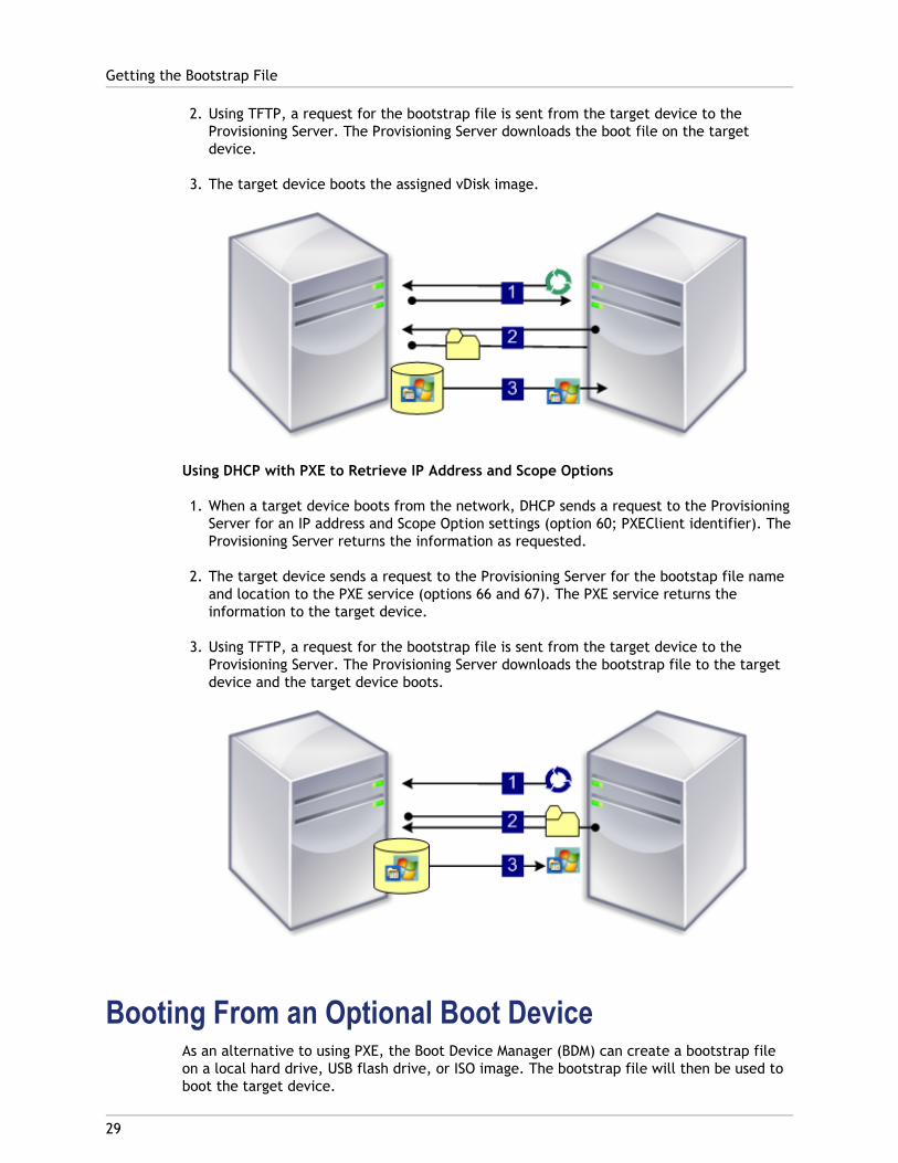
2. Using TFTP, a request for the bootstrap file is sent from the target device to theProvisioning Server. The Provisioning Server downloads the boot file on the targetdevice.
3. The target device boots the assigned vDisk image.
Using DHCP with PXE to Retrieve IP Address and Scope Options
1. When a target device boots from the network, DHCP sends a request to the ProvisioningServer for an IP address and Scope Option settings (option 60; PXEClient identifier). TheProvisioning Server returns the information as requested.
2. The target device sends a request to the Provisioning Server for the bootstap file nameand location to the PXE service (options 66 and 67). The PXE service returns theinformation to the target device.
3. Using TFTP, a request for the bootstrap file is sent from the target device to theProvisioning Server. The Provisioning Server downloads the bootstrap file to the targetdevice and the target device boots.
Booting From an Optional Boot DeviceAs an alternative to using PXE, the Boot Device Manager (BDM) can create a bootstrap fileon a local hard drive, USB flash drive, or ISO image. The bootstrap file will then be used toboot the target device.
Getting the Bootstrap File
29

Note: The BIOS Embedded Bootstrap boot method also exists to allow OEMs to embeddedthe bootstrap file on the target device.
Getting the Bootstrap File
30

31
Selecting a vDisk Access Mode
The vDisk access mode options include:
● Standard Image Mode
● Private Image Mode
Standard Image ModeStandard Image mode allows multiple target devices to stream from a single vDisk image atthe same time; reducing the amount of vDisk management and reducing storagerequirements.
When a vDisk is configured to use Standard Image mode, it is set to read-only mode. Eachtarget device then builds a write cache to store any writes the operating system needs tomake. There are several write-cache options available. Because the vDisk is read-only, eachtime a target device boots, it always boots from a ‘clean’ vDisk. If a machine becomesinfected with a virus or spyware, the target device only needs to reboot the image.
When updates are made to a vDisk in Standard Image mode, changes against the base vDiskimage are captured in a differencing disk file (.aVHD), resulting in a new version of the baseimage. Each new version remains directly associated with the base image. Versioning allowsfor the updates captured in the differencing disk to be staged (Maintenance, Test,Production) before those changes become available to Production devices. If issues areencountered with a version, that version can simply be reverted. For details on versioning,refer to Updating vDisks.
While each target device is using the same vDisk, Provisioning Services personalizes thestreamed image for each target device, providing the information needed to ensure thedevice is uniquely identifiable on the network. In addition, the product provides amechanism to specify additional personality settings for each device. This feature allowsyou to store application specific values in the database and retrieve the target device’sunique value as the device loads. For more details, refer to Managing Target DevicePersonality.
Private Image ModeA vDisk that is in Private image mode closely models how a computer uses a regular harddrive. That is, only one target device can use a Private Image vDisk at a time.
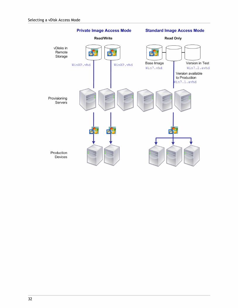
The following illustrates Private Image vDisks (read/write) that are each assigned to asingle Production device, and a Standard Image vDisk (read-only) that is assigned to andshared by a collection of Production devices. For Standard Image vDisks, write cacheoptions include cache on server disk, on a devices hard disk drive, or in the devices RAM.
Selecting a vDisk Access Mode
32
33
Selecting the Write Cache Destination forStandard vDisk Images
Provisioning Services supports several write cache destination options. The write cachedestination for a vDisk is selected on the General tab, which is available from the vDisk FileProperties dialog.
Note: If the cache on local hard-drive type is selected, ensure that the hard-disk drive isformatted with NTFS for Windows devices with a minimum of 500 MB. If the cache on thetarget device RAM and Standard Image mode are selected, the max size of the RAM writecache is determined by the registry setting WcMaxRamCacheMB in the BNIStackParameters. This is a DWORD parameter. If the registry entry does not exist, then thedefault value used is 3584 MB.
The following lists valid write cache destinations:
● Cache on device hard drive
● Cache on device hard drive persisted (experimental phase only)
● Cache in device RAM
● Cache on a server disk
● Cache on server persisted
Cache on Device Hard DriveWrite cache can exist as a file in NTFS format, located on the target-device’s hard drive.This write cache option frees up the Provisioning Server since it does not have to processwrite requests and does not have the finite limitation of RAM.
The hard drive does not require any additional software to enable this feature.
Note: The write cache file is temporary unless the vDisk mode is set to Difference DiskImage mode.

Cache Device Hard Drive Persisted (experimentalphase only)
The same as Cache on device hard drive, except cache persists. At this time, this writecache method is an experimental feature only, and is only supported for NT6.1 or later(Windows 7 and Windows 2008 R2 and later). This method also requires a differentbootstrap. To select the correct bootstrap from the Console, right-clcik on the ProvisioningServer, select Configure Bootstrap. On the General tab, click on the drop-down Bootstrapfile option, then choose CTXBP.BIN. Citrix highly recommends that the local HDD (clientside) drive has enough free space to store the entire vDisk.
Cache in Device RAMWrite cache can exist as a temporary file in the target device’s RAM. This provides thefastest method of disk access since memory access is always faster than disk access.
Cache on a ServerWrite cache can exist as a temporary file on a Provisioning Server. In this configuration, allwrites are handled by the Provisioning Server, which can increase disk IO and networktraffic.
For additional security, the Provisioning Server can be configured to encrypt write cachefiles. Since the write-cache file does exist on the hard drive between reboots, the data willbe encrypted in the event a hard drive is stolen.
Cache on Server PersistentThis cache option allows for the saving of changes between reboots. Using this option, afterrebooting, a target device is able to retrieve changes made from previous sessions thatdiffer from the read only vDisk image. If a vDisk is set to Cache on server persistent, eachtarget device that accesses the vDisk automatically has a device-specific, writable disk filecreated. Any changes made to the vDisk image are written to that file, which is notautomatically deleted upon shutdown.
The file name uniquely identifies the target device by including the target device’s MACaddress and disk identifier. A target device can be assigned to multiple vDisks and thereforehave multiple cache files associated to it.
In order to restore a vDisk that uses Cache Persistent on Server, be sure to backup all vDiskfiles and associated user cache files prior to making any vDisk modifications.
The benefits of using this cache option include:
● Saves target device specific changes that are made to the vDisk image.
Selecting the Write Cache Destination for Standard vDisk Images
34
● Same benefits as Standard Image Mode.
The drawbacks of using this cache option include:
● The cache file is available so long as the file remains valid. Any changes made to thevDisk force the cache file to be marked invalid. For example, if the vDisk is set toPrivate Image Mode, all associated cache files are marked invalid.
Note: Cache files that are marked as invalid are not deleted. Periodically, these filesshould be manually deleted.
Invalidating changes include:
● Placing a vDisk in Maintenance
● vDisk is placed in Private Image mode
● Mapping the drive from the Console
● Changing the location of the write cache file
● Using Automatic update
Selecting the Write Cache Destination for Standard vDisk Images
35
36
Installing and Configuring ProvisioningServices
This chapter describes the Provisioning Services installation wizards that are included in theproduct software, and the installation and configuration procedures required to create anew Provisioning Services implementation.
Note: Provisioning Services product software and components are installed from theproduct CD-ROM or from the product download site.
37
Installation Wizards and Utilities
Citrix LicensingCTX_Licensing.msi installs the Citrix licensing software on a server that can communicatewith Provisioning Servers within your implementation.
Provisioning Services Installation WizardRun PVS_Server.exe or PVS_Server_x64.exe to install the following Provisioning Services’components within a farm:
● Provisioning Services Stream Service
● Network Boot Services (optional)
● Configuration Wizard (runs after the installation wizard to configure installedcomponents and creates the Provisioning Services database)
● Programming Utilities
● Boot Device Manager (BDM)
Note: Installing from a UNC path is not supported.
Provisioning Services Console WizardRun PVS_Console.exe or PVS_Console_x64.exe to install the Console, which also includesthe Boot Device Management utility. The Console can be installed on any machine that cancommunicate with the Provisioning Services database.
Master Target Device Installation WizardFor Windows: PVS_Device.exe or PVS_Device_x64.exe
Installs the target device software on a Master Target Device. The Master Target Device isused to create the ‘golden image,’ which is then saved to a vDisk file using the ImagingWizard.

Upgrade WizardThe Upgrade Wizard facilitates the automation of the upgrade process, and includes thefollowing utilities:
● The UpgradeAgent.exe runs on the target device to upgrade previously installedproduct software.
● The UpgradeManager.exe runs on the Provisioning Server to control the upgrade processon the target device.
Installation Wizards and Utilities
38
39
Overview: Installation and ConfigurationTasks
The following lists the installation and configuration tasks required to create a ProvisioningServices implementation. These tasks are described in detail within this chapter.
1. Planning
2. Getting Product Licensing
3. Installing Provisioning Services Software
4. Configuring the Farm
5. Installing Provisioning Services Console Software
6. Adding Additional Provisioning Servers
7. Assigning Administrator Roles
8. Preparing a Master Target Device for Imaging
9. Building the vDisk Image
10. Assign the First Target Device in a Collection
40
Planning
The following planning procedures must be completed prior to installing and configuringProvisoning Services:
● Select and Configure the MS SQL Database
● Configure Authentication
● Review System Requirements
● Map out Your Farm
Select and Configure the MS SQL DatabaseSelect one of the following MS SQL 2005, MS SQL 2008, MS SQL 2008R2 Server editions to usefor the Provisioning Services Database:
● SQL Server Express Edition
● SQL Server Workgroup Edition
● SQL Server Standard Edition
● SQL Server Enterprise Edition
Note: In some production environments, the database administrator may prefer to createthe Provisioning Services database. In this case, provide the MS SQL databaseadministrator with the file that is created using the DbScript.exe utility. This utility isinstalled with the Provisioning Services software.
Database Sizing
To estimate the size of the database, estimate the size of each table individually, and thenadd those values. The size of a table depends on if the table has indexes, and the type ofindexes. To estimate the database size refer to:http://msdn.microsoft.com/en-us/library/ms187445.aspx, or estimate the size using anexisting database as a sample, and then calculate how much room it takes for each recordin each table (based on this average, a new value can be determined based on the numberof records expected). For example:
Initial Size and Growth
When the database is created, its initial size is 20 MB with a growth size of 10MB.
The database log initial size is 10 MB with a growth size of 10%.
Base Amount
The Base amount that will not change is 112 KB; it is made up of the items below:
● The DatabaseVersion record requires approximately 32 KB.
● The Farm record requires approximately 8 KB.
● The DiskCreate record requires approximately 16 KB.
● The Notifications requires approximately 40 KB.
● The ServerMapped record requires approximately 16 KB.Variable Amount Based On Objects
The following tables can get large if additional items are included:
● Access and Groupings
● Each user group that has access to the system requires approximately 50 KB.
● Each Site record requires approximately 4 KB.
● Each collection that holds Devices requires approximately 10 KB● FarmView
● Each FarmView requires approximately 4 KB.
● Each FarmView/Device relationship requires approximately 5 KB.● SiteView
● Each SiteView requires approximately 4 KB.
● Each SiteView/Device relationship requires approximately 5 KB.● Device
● Each Device requires approximately 2 KB.
● Each DeviceBootstrap requires approximately 10 KB.
● Each Device/Disk relationship requires approximately 35 KB.
● Each Device/Printer relationship requires approximately 1 KB.
● Each Device/Personality requires approximately 1 KB
● Each DeviceStatus when a Device is booted requires approximately 1 KB.
● Each DeviceCustomProperty requires approximately 2 KB.● Disk
● Each unique Disk requires approximately 1 KB.
● Each DiskVersion requires approximately 3 KB.
● Each DiskLocator requires approximately 10 KB.
● Each DiskLocatorCustomProperty requires approximately 2 KB.
Planning
41
● Server
● Each Server requires approximately 5 KB.
● Each ServerIP requires approximately 2 KB.
● Each ServerStatus when a Server is booted requires approximately 1 KB.
● Each ServerCustomProperty requires approximately 2 KB.● Store
● Each Store requires approximately 8 KB.
● Each Store/Server relationship requires approximately 4 KB.● Disk Update
● Each VirtualHostingPool requires approximately 4 KB.
● Each UpdateTask requires approximately 10 KB.
● Each DiskUpdateDevice requires approximately 2 KB.
● Each DiskUpdateDevice/Disk relationship requires approximately 35 KB.
● Each Disk/UpdateTask relationship requires approximately 1 KB.Variable Change Size
The amount that gets larger as changes are made are listed below:
● Each Task (Disk Verison Merge) that has been processed requires approximately 2 KB.
● If auditing is turned on, each change made by the adminstrator in the Console, MCLIor PowerShell PVS interface requires approximately 1 KB.
Database Mirroring
To use the MS SQL Server's database mirroring feature within your farm:
Note: For Provisioning Services to support MS SQL database mirroring, the database needsto be properly configured with High-safety mode with a witness (synchronous).
1. Run the Configuration Wizard, then select the Create farm option.
2. Configure the mirroring database by following Microsoft's instructions.
3. Re-run the Configuration Wizard, then select the Join existing farm option.
4. On the Existing Farm dialog, select the checkbox next to Specify database mirrorfailover partner. Enter the database server and instance name of the database mirrorfailover partner and, if necessary, an optional TCP port.
Note: Refer to Configuring the Farm for details.
Planning
42
Configure AuthenticationProvisioning Services uses Windows authentication. All Provisioning Services components,including the Configuration Wizard and services that access the database, must run in thecontext of the logged-in user.
Services, such as the Stream Process and SOAP Server, need to have the user specificallyconfigured with minimal privileges.
Note: Provisioning Services supports Windows authentication as is recommended byMicrosoft. Microsoft SQL Server authentication is not supported, except when running theConfiguration Wizard.
Configuration Wizard User Permissions
The following MS SQL permissions are required for the user that is running the ConfigurationWizard:
● dbcreator; required for creating the database
● securityadmin; required for creating the SQL logins for the stream and soap services
If the user does not have sufficient SQL privileges, a dialog prompts for a SQL Server userthat has the appropriate permissions (dbcreator and securityadmin).
If using MS SQL Express in a test environment, you can choose to provide the user that isrunning the Configuration Wizard sysadmin privileges (the highest database privilege level).
Note: Alternatively, if the database administrator has provided an empty database, theuser running the Configuration Wizard must be the owner of the database and have the"View any definition permission" (these settings are set by the database administratorwhen the empty database is created).
Service Account Permissions
The user context for the Stream and Soap services requires the following databasepermissions:
● db_datareader
● db_datawriter
● execute permissions on stored procedures
Note: The Configuration Wizard assigns these permissions provided the user hassecurityadmin permissions.
In addition, the service user must have the following system privileges:
● Run as service
● Registry read access
● Program Files\Citrix\Provisioning Services
Planning
43
● Read/write access to any vDisk location
Determine which of the following supported user accounts the Stream and Soap serviceswill run under:
● Network service account
Minimum privilege local account that authenicates on the network as computers domainmachine account
● Specified user account (required when using a Windows Share)
Workgroup or domain user account
● Local system account (for use with SAN)
Note: If using Provisioning Services with XenDesktop, the Soap Server user account musthave XenDesktop Full administrator privileges.
Because authentication is not common in workgroup environments, minimal privilege useraccounts must be created on each server, and each instance must have identicalcredentials (i.e. password).
Caution: Installing SQL Server and Provisioning Services on the same server can causepoor distribution during load balancing. It is highly recommended that they do notco-exist on the same server.
Determine the appropriate security option to use in this farm (only one option can beselected per Farm and the selection you choose impacts Role Based Administration).
● Use Active Directory groups for security (default); select this option if you are on aWindows Domain running Active Directory. This option enables you to leverage ActiveDirectory for Provisioning Services administration roles.
Note: Windows 2000 Domains are no longer supported.
● Use Windows groups for security; select this option if you are on a single server or in aWorkgroup. This option enables you to leverage the Local User/Groups on thatparticular server for Provisioning Services administration roles.
Note: Console users do not directly access the database.
Minimum permissions required for additional Provisioning Services functionality includes:
● Provisioning Services XenDesktop Setup Wizard, Streamed VM Setup Wizard, andImageUpdate service
● vCenter, SCVMM, and XenServer minimum permissions
● XenDesktop minimum permissions (XenDesktop Setup Wizard only)
● SCVMM only. To work with XenDesktop, user must run the following PowerShellcommand; set-ExecutionPolicy unrestricted on SCVMM
● AD account synchronization
Planning
44
● Create, Reset, and Delete permissions
● vDisk
● Mounting permissionsKerberos Security
By default, the Provisioning Services Console, Imaging Wizard, PowerShell snap-in and MCLIuse Kerberos authentication when communicating with the Provisioning Services SOAPService in an Active Directory environment. Part of the Kerberos architecture is for aservice to register (create a service principal name, SPN) with the domain controller(Kerberos Key Distribution Center). The registration is essential as it allows Active Directoryto identify the account that the Provisioning Services SOAP service is running in. If theregistration is not performed, the Kerberos authentication will fail and Provisioning Serviceswill fall back to using NTLM authentication.
The Provisioning Services SOAP Service will register every time the service starts andunregister when the service stops. However, there are times when the registration will failbecause the service user account does not have permission. By default, the Network Serviceaccount and domain administrators have permission while normal domain user accounts donot. There are a few possible workarounds:
1. Use a different account that has permissions to create SPNs.
2. Assign permissions to the service account.
Account Type Permission
Computer Account Write Validated SPN
User Account Write Public InformationCreate the SPNs manually using the SETSPN.EXE tool included with Windows 2008 ordistributed with the Windows Support Tools included on the Windows 2003 operatingsystem disk. As an administrator, run the following commands:
● setspn -a PVSSoap/<hostname> <username>
● setspn -a PVSSoap/<fully qualified domain name> <username>
Note: If the service account is ever changed, the SPNs will need to be removed andnew ones created for the new account. To remove the SPNs, run the followingcommands:
● setspn -d PVSSoap/<hostname> <username>
● setspn -d PVSSoap/<fully qualified domain name> <username>
Review System RequirementsVerify that the following hardware and software requirements are met.
Provisioning Server OS Requirements
Operating Systems
Planning
45
Provisioning Services English on English, Japanese, German, French, Spanish, SimplifiedChinese, Traditional Chinese, Korean, and Russian versions of operating systems aresupported
Windows Server 2003 SP2 (32 or 64-bit); all editions
Windows Server 2008 (32 or 64-bit); all editions
Windows Server 2008 R2 and Windows Server 2008 R2 SP1; Standard, DataCenter, andEnterprise editions
Provisioning Server System Requirements
In most implementations, there is a single vDisk providing the standard image for multipletarget devices. The more target devices using the same vDisk image, the less vDisks need tobe created; making vDisk management easier. In order to have a single vDisk, all targetdevices must have certain similarities to ensure that the OS has all of the drivers it requiresto run properly. The three key components that should be consistent are the motherboard,network card, or video card.
Disk storage management is very important because a Provisioning Server can have manyvDisks stored on it, and each disk can be several gigabytes in size. Your streamingperformance can be improved using a RAID array, SAN, or NAS.
Processor
Intel or AMD x86 or x64 compatible; 2 GHz minimum; 3 GHz preferred; 3.5 GHz DualCore/HT or similar for loads greater than 250 target devices.
Memory
Minimum of 2 GB RAM; 4 GB preferred; 4 GB is required for a larger number of vDisks(greater than 250).
Hard Disk and Storage
There must be enough space on the hard disk to store the vDisks. For example, if youhave a 15 GB hard drive, you can only create a 14 GB vDisk.
Additional requirements depend on several factors such as:
Hard disk capacity requirement of the operating system and applications running on atarget device. It is recommended to add 20% on the base size of the final installedimage.
Private Image Mode – number of target devices using a vDisk in Private Image mode(vDisks in Private Image mode should be backed up daily)
Standard Image Mode – number of target devices using a vDisk in Standard Image mode.
Note: Best practices include making a copy of every vDisk created.
Windows 2003 and 2003 x64; minimum of 250 MB on the application drive.
Minimum Common Storage Sizes
Planning
46
● 250 MB for the database
● 5 GB on a clean Windows system
● 15 GB per vDisk for Vista Class images (estimated)
Additional space per vDisk based on additional significant applications loaded.
Network Adapter
Static IP
Minimum 100 MB Ethernet, 1 GB Ethernet preferred; Dual 1 GB Ethernet for more than250 target devices.
Note: Two NICs often perform better than a single dual-ported NIC.
Required Software
The Provisioning Server install program requires the installation of Windows PowerShell2.0 on each server.
Network Requirements
UDP and TCP Port Requirements
Provisioning Server to Provisioning Server Communication
Each Provisioning Server must be configured to use the same ports (UDP) in order tocommunicate with each other (uses the Messaging Manager). At least five ports mustexist in the port range selected. The port range is configured on the Stream Servicesdialog when the Configuration Wizard is run.
Note: If configuring for a high availability (HA), all Provisioning Servers selected asfailover servers must reside within the same site. HA is not intended to cross betweensites.
The first port in the default range is UDP 6890 and the last port is 6909.
Provisioning Servers to Target Device Communication
Each Provisioning Server must be configured to use the same ports (UDP) in order tocommunicate with target devices (uses the StreamProcess). The port range is configuredusing the Console’s Network tab on the Server Properties dialog.
The default ports include:
UDP 6910, 6911, 6912, 6913, 6914, 6915, 6916, 6917, 6918, 6919, 6920, 6921, 6922,6923, 6924, 6925, 6926, 6927, 6928, 6929 and 6930.
Login Server Communication
Each Provisioning Server that will be used as a login server must be configured on theStream Servers Boot List dialog when the Configuration Wizard is run.
The default port for login servers to use is UDP 6910.
Planning
47
Console Communication
The Soap Server is used when accessing the Console. The ports (TCP) are configured onthe Stream Services dialog when the Configuration Wizard is run.
The default ports are TCP 54321 and 54322 (Provisioning Services automatically sets asecond port by incrementing the port number entered by 1; 54321 + 1).
If this value is modified, the following command must be run.
For Powershell: MCLI-Run SetupConnection
For MCLI: MCLI Run SetupConnection
Note: Refer to the Provisioning Server Programmers Guides for details.
TFTP Communication
The TFTP port value is stored in the registry:
HKEY_LOCAL_MACHINE\SYSTEM\CurrentControlSet\Services\BNTFTP\Parameters Port
The TFTP port defaults to UDP 69.
TSB Communication
The TSB port value is stored in the registry:
HKEY_LOCAL_MACHINE\SYSTEM\CurrentControlSet\Services\PVSTSB\Parameters Port
The TSB port defaults to UDP 6969.
Port Fast
Port Fast must be enabled.
Network Card
PXE 0.99j, PXE 2.1 or later.
Network Addressing
DHCP
Target Device Requirements
Note: Dual boot vDisk images are not supported.
Target devices are identified by the operating system that runs on that device. Thefollowing table lists the supported operating systems for target devices.
Windows Target Device
(32 or 64 bit)
Planning
48
Provisioning Services English on English, Japanese, German, French, Spanish, SimplifiedChinese, Traditional Chinese, Korean, and Russian versions of operating systems aresupported.
Windows Server 2003 SP1 (32 or 64-bit); all editions
Windows Server 2008 (32 or 64-bit); all editions
Windows Server 2008 R2 and Windows Server 2008 R2 SP1:
● Standard
● DataCenter
● EnterpriseWindows XP Professional (32 or 64-bit)
Windows Vista (32 or 64-bit):
● Business
● Enterprise
● Ultimate (retail licensing)
Note: The Ultimate edition of Windows Visa is only supported in Private Imagemode.
Windows 7 and Windows 7 SP1 (32 or 64-bit):
● Enterprise
● Professional
● Ultimate
Note: The Ultimate edition of Windows 7 is only supported in Private Image mode.Licensing Key Considerations
Windows Vista Business, Windows Enterprise, Windows 7, and Windows Server 2008 andServer 2008 R2 are deployed with either Key Management Server (KMS) or with MicrosoftMultiple Activation Key (MAK) volume licensing keys. Windows Office 2010 is deployedwith KMS.
Note: In order for MAK licensing to work, the Volume Activation Management Tool(VAMT) must be installed on all login servers within a farm.This tool is available fromhttp://www.microsoft.com/downloads/en/details.aspx?FamilyID=ec7156d2-2864-49ee-bfcb-777b898ad582&displaylang=en.
Both Private and Standard Image Modes support MAK and KMS.
Volume licensing is configured within the vDisk image when the Imaging Wizard is run onthe Master target device. Volume licensing is configured for the vDisk file on theMicrosoft Volume Licensing tab, which is available from the Consoles' vDisk FileProperties dialog.
Supported File System Types
Planning
49
NTFS
Provisioning Services Console Requirements
Processor
Minimum 1 GHz, 2 GHz preferred
Memory
Minimum 1 GB, 2 GB preferred
Hard Disk
Minimum 500 MB
Operating System
Windows Server 2003 (32 or 64-bit); all editionsWindows Server 2008 (32 or 64-bit); all editionsWindows Server 2008 R2; Standard, DataCenterand Enterprise EditionsWindows XP Professional (32 or 64-bit)Windows Vista (32 or 64-bit)
● Business
● Enterprise
● Ultimate (retail licensing)Other
Required:
MMC 3.0
Windows PowerShell 2.0
Optional: Adobe Acrobat Reader highly recommended.
Supported ESD Servers for vDisk Update Management
● WSUS Server – 3.0 SP2
● System Center Configuration Management (SCCM) – SCCM ConfigMgr 2007 SP2, SCCM2012 (Beta version)
Supported Hypervisors
● XenServer 5.6 SP2, XenServer 6.0
● System Center Virtual Machine Management (SCVMM) – SCVMM 2008 R2 SP1, SCVMM2012
● ESX 4.1
Planning
50
● HyperV 2008 R2 SP1
Streamed VM Setup Wizard Requirements
● One or more hypervisor hosts exist with a configured template.
● A Device Collection exists in the Provisioning Services Site.
● A vDisk in Standard Image mode exists, to be associated with selected VM template.
● The Provisioning Services Console user account was added to a PVS SiteAdmin groupor above.
● If using Active Directory, when creating new accounts in the Console, the user needsthe Active Directory Create Accounts permission. To use existing accounts, ActiveDirectory accounts have to already exist in a known OU for selection.
XenDesktop Setup Wizard Requirements
● A XenDesktop controller.
● One or more configured XenDesktop hosts with identical templates exist.
● A Device Collection has been created in the Provisioning Services Site.
● vDisks image mode is set to Standard Image for the selected VM template.
● A Provisioning Services Console user account is configured as a XenDesktopadministrator and it has been added to a PVS SiteAdmin group or higher.
● System Center Virtual Machine Management (SCVMM) servers require that PowerShell2.0 is installed and configured for the number of connections. The number ofrequired connections for an SCVMM server should be greater than or equal to thenumber of hosted hypervisors used by the setup wizard for virtual machine cloning.For example: to set connections to 25 from a Powershell prompt, run: winrm setwinrm/config/winrs @{MaxShellsPerUser="25"}winrm set winrm/config/winrs@{MaxConcurrentUsers="25"} .
● For SCVMM to work with XenDesktop, the user must run the following PowerShellcommand; set-ExecutionPolicy unrestricted on SCVMM.
● If using multiple NICs, the XenDesktop wizard assumes that the first NIC is theProvisioning Services' NIC, and therefore changes it in accordance with the virtualmachine network in the DDC. This is the first NIC listed in the virtual machinesproperties.
● If using Active Directory, when creating new accounts in the Console, the user needsthe Active Directory Create Accounts permission. To use existing accounts, ActiveDirectory accounts have to already exist in a known OU for selection.
Planning
51
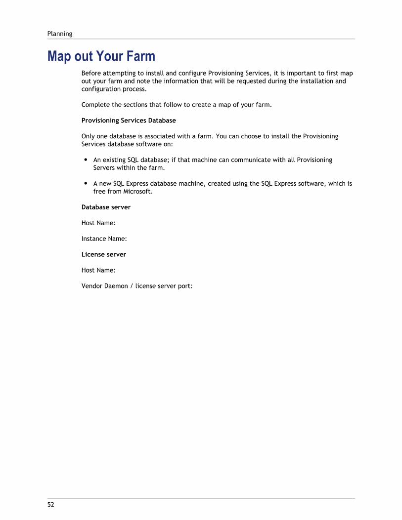
Map out Your FarmBefore attempting to install and configure Provisioning Services, it is important to first mapout your farm and note the information that will be requested during the installation andconfiguration process.
Complete the sections that follow to create a map of your farm.
Provisioning Services Database
Only one database is associated with a farm. You can choose to install the ProvisioningServices database software on:
● An existing SQL database; if that machine can communicate with all ProvisioningServers within the farm.
● A new SQL Express database machine, created using the SQL Express software, which isfree from Microsoft.
Database server
Host Name:
Instance Name:
License server
Host Name:
Vendor Daemon / license server port:
Planning
52
53
Getting Product Licensing
The Citrix License Server must be installed on a server within the farm that is able tocommunicate with all Provisioning Servers within the farm.
Consider the following options when deciding which server to use as the license server:
● Single System: Same system as Provisioning Services; for evaluations, test labs, orimplementations with one Citrix product.
● Stand-alone: Separate system that has an existing license server installed; for largerimplementations or implementations using multiple Citrix products.
● Point to an existing license server.
Licensing Grace Periods
There are three types of grace periods provided by Citrix Licensing. Provisioning Servicesimplements these grace periods as follows:
● Out of Box Grace Period (OOBGP) is 30 days (720 hours): If Provisioning Services isinstalled prior to either installation of a Citrix License Server or the allocation of validproduct edition licenses for XenApp, XenDesktop, XenServer, Essentials for Hyper-V orProvisioning Services for Datacenters, it will provision unlimited systems for a period of30 days (96 hours is standard across most Citrix products prior to Provisioning Services6.0 and XenDesktop 5 SP1). If this grace period lapses, provisioning sessions that arealready running will continue to run, but any new or restarted provisioning sessions willbe subject to the 'No Valid License Grace Period' message on the provisioned client.
● License Server Connectivity Outage Grace Period is 30 days (720 hours): Ifconnectivity to the Citrix License Server is lost, Provisioning Services will continue toprovision systems for a period of 30 days (720 hours; this is standard across most Citrixproducts). If this grace period lapses, provisioning sessions that are already running willcontinue to run, but any new or restarted provisioning sessions will be subject to the'No Valid License Grace Period' message on the provisioned client.
● No Valid License Grace Period for Clients for 5.6 = 3 hours, 5.6 SP1 = 96 hours: IfProvisioning Services cannot obtain a valid license for a provisioning session, a warningdialog displays on the provisioned system, but the session is allowed to continue runningfor the period of time as indicated above. When this grace period lapses, each affectedsession is shut down. This grace period may apply in the following scenarios:
● No valid edition licenses for XenApp, XenDesktop, XenServer, Essentials for Hyper-Vor Provisioning Services are available.
● Licenses are available, but have expired (applies to Evaluation, NFR, and InternalUse license).
● The SA Expiration date of the licenses precedes the release date of the version ofProvisioning Services that is being used.
Installing the License ServerDownload or run CTX_Licensing.msi from the Product Installation CD-ROM.
Note: If Provisioning Services is installed after the license server or if new licenses areadded, the Stream Service must be restarted.
For product licensing documentation, open Citrix eDocs , expand the Technologies section,and then select Licensing Your Product.
Getting Product Licensing
54
55
Installing Provisioning Services ServerSoftware
Install any Windows service packs, drivers, and updates before installing the ProvisioningServices software.
Note: When installing Provisioning Services software on a server that has previousversions of .Net installed, Citrix recommends rebooting if prompted to do so during the.Net installation.
Note: This installation task is for new Provisioning Services implementations. For upgradetasks, refer to Upgrading from Previous Releases. The software can also be installedsilently. Refer to Silent Install
Complete the steps that follow to install the services and applications required to create aProvisioning Server.
1. Click on the appropriate platform-specific install option. The Provisioning ServicesWelcome window appears.
2. Click Next. The Product License Agreement appears.
3. Scroll to the end to accept the terms in the license agreement, then click Next tocontinue. The Customer Information dialog appears.
4. Optionally, type or select your user name and organization name in the appropriatetext boxes, then click Next. The Destination Folder dialog appears.
5. Click Change, then enter the folder name or navigate to the appropriate folder wherethe software should be installed, or click Next to install Provisioning Services to thedefault folder. The Setup Type dialog appears.
6. Select the radio button that best describes the installation to perform:
● Complete - Installs all components and options on this computer (default).
● Custom - Choose which components to install and where to install thosecomponents.
Note: Installing the Network Boot Services does not activate them. If uncertain aboutthe need for any of these services, choose the Complete installation option.
7. Click Next.
8. If you select Complete, the ‘Ready to Install the Program’ dialog appears. If youselected Custom, the ‘Custom Setup’ dialog appears. This dialog provides a ‘FeatureDescription’ text box that provides a description for the selected component as well asthe space required to install that component.
● Expand each component icon and select how that component is to be installed.
● After making component selections, click Next. The ‘Ready to Install the Program’dialog appears. Or, click Cancel to close the wizard without making systemmodifications.
9. On the ‘Ready to Install the Program’ dialog, click Install to continue with theinstallation process (the installation may take several minutes).
10. The ‘Installation Wizard Completed’ message displays in the dialog when thecomponents and options are successfully installed.
Note: The Installation Wizard can be re-run to install additional components at alater time, or re-run on a different computer to install select components on aseparate computer.
11. Click Finish to exit the Installation Wizard. The Provisioning Services ConfigurationWizard automatically opens.
Note: Although Provisioning Services does not require that you restart the server afterinstalling the product software, in some instances, a Microsoft message may appearrequesting a restart. If this message appears, complete Task 4: Configuring the Farmusing the Configuration Wizard, before restarting the server. If this message appears andthe server is not restarted, the removeable drive may not appear.
Silent Product Software InstallTarget devices, Provisioning Servers, and Consoles can be silently installed to a defaultinstallation directory using the following command:
<Installer Name>.exe /s /v"/qn"
Or, use the following to set a different destination:
<Installer Name>.exe /s /v"/qn INSTALLDIR=D:\Destination"
Installing Provisioning Services Server Software
56

57
Configuring the Farm
Run the Configuration Wizard on a Provisioning Server when creating a new farm, addingnew Provisioning Servers to an existing farm, or reconfiguring an existing ProvisioningServer.
When configuring a Provisioning Server, consider the following:
● All Provisioning Servers within a farm must share the same database to locate vDisks fortarget devices on shared storage devices within the farm. If that shared storage deviceis a Windows network share, refer to configuration information described in theAdministrator’s Guide, Managing Network Components section. If that shared storagedevice is a SAN, no additional configuration is necessary.
● To properly configure the network services, be sure that you understand networkservice options and settings.
Note: If all Provisioning Servers in the farm share the same configuration settings such assite and store information, consider Running the Configuration Wizard Silently.
Configuration Wizard SettingsBefore running the Configuration Wizard, be prepared to make the following selections:
Note: The Configuration Wizard can also be run silently on servers that share similarconfiguration settings. For details, refer to Running the Configuration Wizard Silently.
● Network Topology
● Identify the Farm
● Identify the Database
● Identify the Site
● License Server Settings
● Select Network Cards for the Stream Service
● Configure Bootstrap Server
Note: If errors occur during processing, the log is written to a ConfigWizard.log file,which is located at:
● C:\ProgramData\Citrix\Provisioning Services for 2008 and newer.
● C:\Documents and Settings\All Users\ApplicationData\Citrix\Provisioning Services for 2003.
Starting the Configuration WizardThe Configuration Wizard starts automatically after Provisioning Services software isinstalled. The wizard can also be started by selecting:
1. Start > All Programs > Citrix > Provisioning Services > Provisioning ServicesConfiguration Wizard
2. After starting the Configuration Wizard, click Next to begin the configuration tasks thatfollow.
Note: When running the Configuration Wizard, the tasks that appear depend on thenetwork service options that are selected and the purpose for running the wizard.
Network TopologyComplete the network configuration steps that follow.
1. Select the network service to provide IP addresses
Note: Use existing network services if possible. If for any reason existing networkservices can not be used, choose to install the network services that are madeavailable during the installation process.
To provide IP addresses to target devices, select from the following network serviceoptions:
● If the DHCP service is on this server, select the radio button next to one of thefollowing network services to use, then click Next:
● Microsoft DHCP
● Provisioning Services BOOTP service
● Other BOOTP or DHCP service● If the DHCP service is not on this server, select the radio button next to The
service is running on another computer, then click Next.2. Select the network service to provide PXE boot information
Each target device needs to download a boot file from a TFTP server.
Select the network service to provide target devices with PXE boot information:
● If you choose to use this Provisioning Server to deliver PXE boot information, selectThe service that runs on this computer, then select from either of the followingoptions, then click Next:
Configuring the Farm
58
● Microsoft DHCP (options 66 and 67)
● Provisioning Services PXE Service
● If Provisioning Services will not deliver PXE boot information, select Theinformation is provided by a service on another device option, then click Next.
Identify the FarmNote: When configuring the farm, the combination of the database name and farm namecannot exceed 54 characters. Exceeding this limitation may cause the farm name todisplay truncated in the Existing Farms screen.
1. Select from the following farm options:
● Farm is already configured
Select this option to reconfigure an existing farm, then continue on to the“Configure user account settings” procedure. This option only appears if a farmalready exists.
● Create farm
a. On the Farm Configuration dialog, select the Create Farm radio button tocreate a new farm, then click Next.
b. Use the Browse button to browse for existing SQL databases and instances inthe network, or type the database server name and instance. Optionally, entera TCP port number to use to communicate with this database server.
c. To enable database mirroring, enable the Specify database mirror failoverpartner option, then type or use the Browse button to identify the failoverdatabase server and instance names. Optionally, enter a TCP port number touse to communicate with this server.
Note: Refer to Database Mirroring in the Provisioning ServicesAdministrator's Guide for more information.
d. Click Next to continue on to the “Selecting the database location” procedure.● Join existing farm
a. On the Farm Configuration dialog, select the Join Existing Farm radio button toadd this Provisioning Server to an existing farm, then click Next.
b. Use the Browse button to browse for the appropriate SQL database andinstance within the network.
c. Select the farm name that displays by default, or scroll to select the farm tojoin.
Note: More than one farm can exist on a single server. This configuration iscommon in test implementations.
Configuring the Farm
59

d. To enable database mirroring, enable the Specify database mirror failoverpartner option, then type or use the Browse button to identify the failoverdatabase server and instance names. Optionally, enter a TCP port number touse to communicate with this server.
Note: Refer to Database Mirroring in the Provisioning ServicesAdministrator's Guide for more information.
e. Click Next.
f. Select from the following site options, then click Next:
● Existing Site: Select the site from the drop-down menu to join an existingsite.
● New Site: Create a site by typing the name of the new site and acollection.
Continue on to Configure user account settings procedure.
Identify the DatabaseOnly one database exists within a farm. To identify the database, complete the steps thatfollow.
1. Select the database location If the database server location and instance have not yetbeen selected, complete the following procedure.
a. On the Database Server dialog, click Browse to open the SQL Servers dialog.
b. From the list of SQL Servers, select the name of the server where this databaseexists and the instance to use (to use the default instance, SQLEXPRESS, leave theinstance name blank). In a test environment, this may be a staged database.
Note: When re-running the Configuration Wizard to add additional ProvisioningServers database entries, the Server Name and Instance Name text boxes arealready populated. By default, SQL Server Express installs as an instance named‘SQLEXPRESS’.
c. Click Next. If this is a new farm, continue on to the “Defining a Farm” procedure.2. To change the database to a new database
a. On the old database server, perform a backup of the database to a file.
b. On the new database server, restore the database from the backup file.
c. Run the Configuration Wizard on each Provisioning Server.
d. Select Join existing farm on the Farm Configuration dialog.
e. Enter the new database server and instance on the Database Server dialog.
f. Select the restored database on the Existing Farm dialog.
g. Select the site that the Server was previously a member of on the Site dialog.
Configuring the Farm
60

h. Click Next until the Configuration Wizard finishes.
3. Define a farm. Select the security group to use:
● Use Active Directory groups for security
Note: When selecting the Active Directory group to act as the Farm Administratorfrom the drop-down list, choices include any group the current user belongs to.This list includes Builtin groups, which are local to the current machine. Avoidusing these groups as administrators, except for test environments. Also, beaware that some group names may be misleading and appear to be Domaingroups, which are actually Local Domain groups. For example:ForestA.local/Builtin/Administrators.
● Use Windows groups for security4. Click Next.
Continue on to the“Selecting the license server” procedure.
Create a New Store for a New FarmA new store can be created and assigned to the Provisioning Server being configured:
Note: The Configuration Wizard only allows a server to create or join an existing store ifit is new to the database. If a server already exists in the database and it rejoins a farm,the Configuration Wizard may prompt the user to join a store or create a new store, butthe selection is ignored.
1. On the New Store page, name the new Store.
2. Browse or enter the default path (for example: C:\PVSStore) to use to access this store,then click Next. If an invalid path is selected, an error message appears. Re-enter avalid path, then continue. The default write cache location for the store is locatedunder the store path for example: C:\PVSStore\WriteCache.
Configuring the Farm
61
Identify the Site1. When joining an existing farm, identify the site where this Provisioning Server is to be a
member, by either creating a new site or selecting an existing site within the farm.When a site is created, a default target device collection is automatically created forthat site.
● Create a new site
a. On the Site page, enable the New Site radio button.
b. In the Site Name text box, type the new site name where this ProvisioningServer is to be a member.
c. In the Collection Name, accept the default collection, Collection, or create anew default collection name to associate with this Provisioning Server, thenclick Next.
● Select an existing site
a. On the Site page, enable the Existing Site radio button. (The default site nameis Site.)
b. Select the appropriate site from the drop-down list, then click Next.
c. Create a new store or select an existing store on the Store page, then clickNext.
Select the License ServerNote: When selecting the license server, ensure that all Provisioning Server’s in the farmare able to communicate with that server in order to get the appropriate productlicenses.
1. Enter the name (or IP address) and port number of the license server (default is 27000).The Provisioning Server must be able to communicate with the license server to get theappropriate product licenses.
2. Optionally, select the checkbox Validate license server version and communicationtoverify that the license server is able to communicate with this server and that theappropriate version of the license server is being used. If the server is not able tocommunicate with the license server, or the wrong version of the license server is beingused, an error message displays and does not allow you to proceed.
3. Click Next to continue on to the“Configure user account settings” procedure.
Configure User Account SettingsThe Stream and Soap services run under a user account.
1. On the User Account dialog, select the user account that the Stream and Soap serviceswill run under:
Configuring the Farm
62
● Specified user account (required when using a Windows Share; workgroup ordomain user account)
Type the user name, domain, and password information in the appropriate textboxes.
● Local system account (for use with SAN)
2. Select the checkbox next to the Configure the database for the account option, if youselected Specified user account, which adds the appropriate database roles(Datareader and Datawriter) for this user.
3. Click Next, then continue on to the“Selecting network cards for the Stream Service”procedure.
Select Network Cards for the Stream ServiceNote: If multiple network adapters are selected, they must be configured with the sameIP subnet address. For example: IP subnet: 100.100.10.x; IP subnet mask 255.255.255.0
1. Select the checkbox next to each of the network cards that the Stream Service can use.
2. Enter the base port number that will be used for network communications in the Firstcommunications port: text box.
Note: A minimum of 20 ports are required within the range. All Provisioning Serverswithin a farm must use the same port assignments.
3. Select the Soap Server port (default is 54321) to use for Console access, then clickNext.
Continue on to the “Selecting the bootstrap server” procedure.
Configure Bootstrap ServerComplete the steps that follow to identify the bootstrap server and configure the bootstrapfile location.
Note: Bootstrap configurations can be reconfigured by selecting the Configure Bootstrapoption from the Provisioning Services Action menu in the Console.
1. Select the bootstrap server. To use the TFTP service on this Provisioning Server:
a. Select the Use the TFTP Service option, then enter or browse for the boot file. Thedefault location is: C:\Documents and Settings\AllUsers\ProgramData\Citrix\Provisioning Services\Tftpboot
If a previous version of Provisioning Services was installed on this server, and thedefault location is:
C:\Program Files\Citrix\Provisioning Services\TftpBoot
Configuring the Farm
63

You must run the Configuration Wizard to change the default location to:
C:\Documents and Settings\All Users\ProgramData orApplicationData\Citrix\Provisioning Services\Tftpboot
If the default is not changed, the bootstrap file can not be configured from theConsole and target devices will fail to boot; receiving a ‘Missing TFTP’ errormessage.
b. Click Next.
2. Select Provisioning Servers to use for the boot process:
a. Use the Add button to add additional Provisioning Servers to the list, the Editbutton to edit existing information, or Remove to remove the Provisioning Serverfrom the list. Use the Move up or Move down buttons to change the ProvisioningServer boot preference order. The maximum length for the server name is 15characters. Do not enter FQDN for the server name. In an HA implementation, atleast two Provisioning Servers must be selected as boot servers.
b. Optionally, highlight the IP address of the Provisioning Server that target deviceswill boot from, then click Advanced. The Advanced Stream Servers Boot Listappears.
The following table describes advanced settings that you can choose from. Aftermaking your selections, click OK to exit the dialog, then click Next to continue.
Table 1. Advanced Stream Servers Boot List
Verbose Mode Select the Verbose Mode option if youwant to monitor the boot process onthe target device (optional) or viewsystem messages.
Interrupt Safe Mode Select Interrupt Safe Mode if you arehaving trouble with your target devicefailing early in the boot process. Thisenables debugging of target devicedrivers that exhibit timing or bootbehavior problems
Advanced Memory Support This setting enables the bootstrap towork with newer Windows OS versionsand is enabled by default. Only disablethis setting on older XP or WindowsServer OS 32 bit versions that do notsupport PAE, or if your target device ishanging or behaving erratically in earlyboot phase.
Configuring the Farm
64
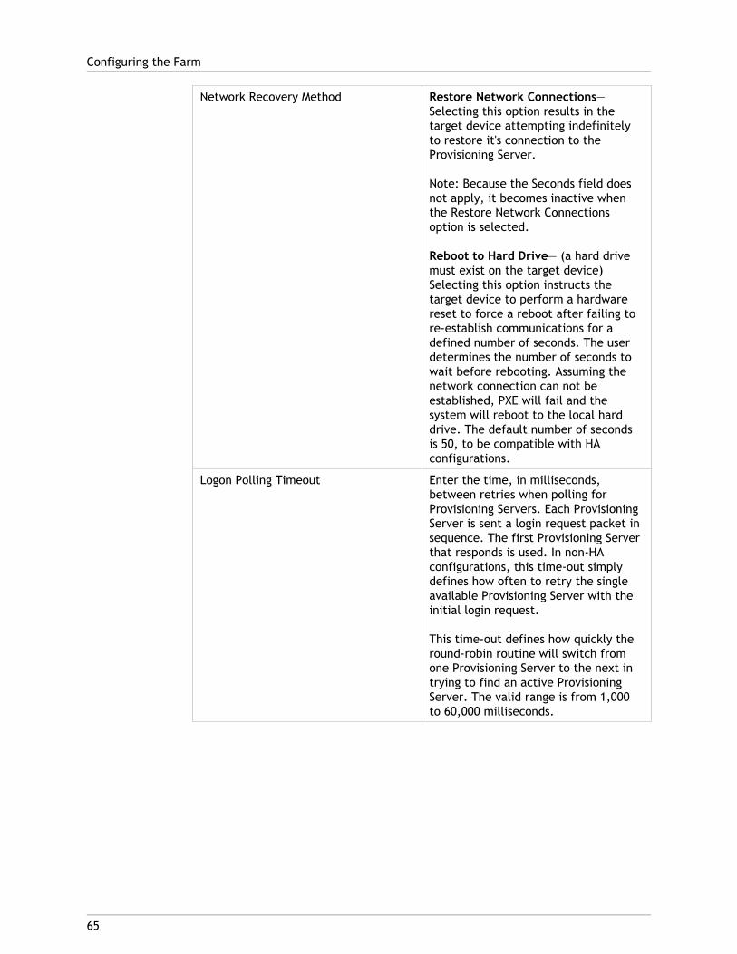
Network Recovery Method Restore Network Connections—Selecting this option results in thetarget device attempting indefinitelyto restore it's connection to theProvisioning Server.
Note: Because the Seconds field doesnot apply, it becomes inactive whenthe Restore Network Connectionsoption is selected.
Reboot to Hard Drive— (a hard drivemust exist on the target device)Selecting this option instructs thetarget device to perform a hardwarereset to force a reboot after failing tore-establish communications for adefined number of seconds. The userdetermines the number of seconds towait before rebooting. Assuming thenetwork connection can not beestablished, PXE will fail and thesystem will reboot to the local harddrive. The default number of secondsis 50, to be compatible with HAconfigurations.
Logon Polling Timeout Enter the time, in milliseconds,between retries when polling forProvisioning Servers. Each ProvisioningServer is sent a login request packet insequence. The first Provisioning Serverthat responds is used. In non-HAconfigurations, this time-out simplydefines how often to retry the singleavailable Provisioning Server with theinitial login request.
This time-out defines how quickly theround-robin routine will switch fromone Provisioning Server to the next intrying to find an active ProvisioningServer. The valid range is from 1,000to 60,000 milliseconds.
Configuring the Farm
65

Login General Timeout Enter the time-out, in milliseconds, forall login associated packets, except theinitial login polling time-out. Thistime-out is generally longer than thepolling time-out, because theProvisioning Server needs time tocontact all associated servers, some ofwhich may be down and will requireretries and time-outs from theProvisioning Server to the otherProvisioning Servers to determine ifthey are indeed online or not. Thevalid range is from 1,000 to 60,000milliseconds.
c. Verify that all configuration settings are correct, then click Finish.
Configuring the Farm
66
67
Running the Configuration Wizard Silently
Run the Configuration Wizard silently to configure multiple Provisioning Servers that shareseveral of the same configuration settings such as the farm, site, and store locations.
PrerequisiteThe Configuration Wizard must first be run on any Provisioning Server in the farm that hasthe configuration settings that will be used in order to create the Provisioning Servicesdatabase and to configure the farm.
The basic steps involved in the silent configuration of servers within the farm include:
● Create a ConfigWizard.ans file from a configured Provisioning Server in the farm.
● Copy the ConfigWizard.ans file onto the other servers within the farm, and modify theIP address in the ConfigWizard.ans file to match each server in the farm.
● Run the ConfigWizard.exe with the /a parameter.
To Create the ConfigWizard.ans File1. Run the ConfigWizard.exe with the /s parameter on a configured server.
2. When selecting farm settings on the Farm Configuration page, choose the Join existingfarm option.
3. Continue selecting configuration settings on the remaining wizard pages, then clickFinish.
4. Copy the resulting ConfigWizard.ans file from the Provisioning Services Application Datadirectory. The location for this directory varies depending on the Windows version. ForWindows 2003, use \Documents and Settings\All Users\ApplicationData\Citrix\Provisioning Services. For Windows 2008 and Windows 2008 R2, use\ProgramData\Citrix\Provisioning Services.
To Copy and Modify the ConfigWizard.ans File1. For each server that needs to be configured, copy the ConfigWizard.ans file to the
Provisioning Services Application Data directory.
2. Edit the StreamNetworkAdapterIP= so that is matches the IP of the server beingconfigured. If there is more than one IP being used for Provisioning Services on theserver, add a comma between each IP address.
To Run the ConfigWizard.exe SilentlyTo configure servers, run the ConfigWizard.exe with /a parameter on each server thatneeds to be configured.
Note: To get the list of valid ConfigWizard parameters:
1. Run the ConfigWizard.exe with the /? parameter.
2. Open the resulting ConfigWizard.out file from the ConfigWizard.ans file from theProvisioning Services Application Data directory.
3. Scroll down to the bottom of the file to view all valid parameters.
Note: To get the list of valid ConfigWizard.ans commands with descriptions:
1. Run the ConfigWizard.exe with the /c parameter.
2. Open the resulting ConfigWizard.out file from the ConfigWizard.ans file from theProvisioning Services Application Data directory.
3. Scroll down to the bottom of the file to view all valid parameters.
Running the Configuration Wizard Silently
68
69
Installing Provisioning Services ConsoleSoftware
The Provisioning Services Console can be installed on any machine that can communicatewith the Provisioning Services database.
Note: The Console installation requires Windows Powershell 2.0. The Console installationincludes the Boot Device Management utility.
1. Run the appropriate platform-specific install option; PVS_Console.exe orPVS_Console_x64.exe.
2. Click Next on the Welcome screen. The Product License Agreement appears.
3. Accept the terms in the license agreement, then click Next to continue. The CustomerInformation dialog appears.
4. Type or select your user name and organization name in the appropriate text boxes.
5. Enable the appropriate application user radio button, then click Next. The DestinationFolder dialog appears.
6. Click Change, then enter the folder name or navigate to the appropriate folder wherethe software should be installed, or click Next to install the Console to the defaultfolder. The Setup Type dialog appears.
7. Select the radio button that best describes the installation to perform:
● Complete - Installs all components and options on this computer (default).
● Custom - Choose which components to install and where to install thosecomponents.
8. Click Next.
9. If you select Complete, the ‘Ready to Install the Program’ dialog appears. If youselected Custom, the ‘Custom Setup’ dialog appears. This dialog provides a ‘FeatureDescription’ text box that provides a description for the selected component as well asthe space required to install that component.
● Expand each component icon and select how that component is to be installed.
● After making component selections, click Next. The ‘Ready to Install the Program’dialog appears. Or, click Cancel to close the wizard without making systemmodifications.
10. On the ‘Ready to Install the Program’ dialog, click Install to continue with theinstallation process (the installation may take several minutes).
11. The ‘Installation Wizard Completed’ message displays in the dialog when thecomponents and options are successfully installed.

Note: The Installation Wizard can be re-run to install additional components at alater time, or re-run on a different computer to install select components on aseparate computer.
Installing Provisioning Services Console Software
70

71
Adding Additional Provisioning Servers
To add additional Provisioning Servers, install the Provisioning Services software on eachserver that is to a member of the farm. Run the Provisioning Services Installation Wizard,then the Configuration Wizard on each server.
Note: The maximum length for the server name is 15 characters. Do not enter FQDN forthe server name
When the Configuration Wizard prompts for the site to add the server to, choose an existingsite or create a new site.
After adding Provisioning Servers to the site, start the Console and connect to the farm.Verify that all sites and servers display appropriately in the Console window.
72
Managing Administrative Roles
The ability to view and manage objects within a Provisioning Server implementation isdetermined by the administrative role assigned to a group of users. Provisioning Servicesmakes use of groups that already exist within the network (Windows or Active DirectoryGroups). All members within a group will share the same administrative privileges within afarm. An administrator may have multiple roles if they belong to more than one group.
The following administrative roles can be assigned to a group:
● Farm Administrator
● Site Administrator
● Device Administrator
● Device Operator
After a group is assigned an administrator role through the Console, if a member of thatgroup attempts to connect to a different farm, a dialog displays requesting that aProvisioning Server within that farm be identified (the name and port number). You are alsorequired to either use the Windows credentials you are currently logged in with (defaultsetting), or enter your Active Directory credentials. Provisioning Services does not supportusing both domain and workgroups simultaneously.
When the information is sent to and received by the appropriate server farm, the role thatwas associated with the group that you are a member of, determines your administrativeprivileges within this farm. Group role assignments can vary from farm to farm.
73
Preparing a Master Target Device forImaging
A Master Target Device refers to a target device from which a hard disk image is built andstored on a vDisk. Provisioning Services then streams the contents of the vDisk created fromthe Master Target Device to other target devices.
● Preparing the Master Target Device’s Hard Disk
● Configuring a Master Target Device’s BIOS
● Configuring Network Adapter BIOS
● Installing Master Target Device Software
Preparing the Master Target Device's Hard DiskThe Master Target Device is typically different from subsequent target devices because itinitially contains a hard disk. This is the hard disk that will be imaged to the vDisk. Ifnecessary, after imaging, the hard disk can be removed from the Master Target Device.
In order to support a single vDisk, that is shared by multiple target devices, those devicesmust have certain similarities to ensure that the operating system has all required drivers.The three key components that must be consistent include the:
● Motherboard
● Network card, which must support PXE
● Video card
However, the Provisioning Services Common Image Utility allows a single vDisk tosimultaneously support different motherboards, network cards, video cards, and otherhardware devices.
If target devices will be sharing a vDisk, the Master Target Device serves as a ‘template’ forall subsequent diskless target devices as they are added to the network. It is crucial thatthe hard disk of Master Target Device be prepared properly and all software is installed onit in the proper order:
Note: Follow the instructions below after installing and configuring the ProvisioningServer and creating target devices.
Software must be installed on the Master Target Device in the order that follows:
1. Windows Operating System
2. Device Drivers
3. Service Packs Updates
4. Target Device Software
Applications can be installed before or after the target device software is installed. Iftarget devices will be members of a domain, and will share a vDisk, additional configurationsteps must be completed (refer to Managing Domain Accounts in the Administrator’s Guide,before proceeding with the installation).
Note: Dual boot vDisk images are not supported.
Configuring a Master Target Device's BIOSThe following steps describe how to configure the target devices system’s BIOS and the BIOSextension provided by the network adapter, to boot from the network. Different systemshave different BIOS setup interfaces – if necessary, consult the documentation that camewith your system for further information on configuring these options.
1. If the target device BIOS has not yet been configured, re-boot the target device andenter the system’s BIOS setup. (To get to BIOS setup, press the F1, F2, F10 or Deletekey during the boot process. The key varies by manufacturer).
2. Set the network adapter to On with PXE.
Note: Depending on the system vendor, this setting may appear differently.
3. Configure the target device to boot from LAN or Network first. Optionally, select theUniversal Network Driver Interface; UNDI first, if using a NIC with Managed Boot Agent(MBA) support.
Note: On some older systems, if the BIOS setup program included an option thatpermitted you to enable or disable disk-boot sector write protection, ensure that theoption is disabled before continuing.
4. Save changes, then exit the BIOS setup program.
5. Boot the target device from it’s hard drive over the network to attach the vDisk to thetarget device.
Configuring Network Adapter BIOSThis procedure is only necessary for older systems.
1. Re-boot the Master Target Device.
2. Configure the network adapter’s BIOS extension through setup.
During the system boot, the network adapter’s BIOS extension will present aninitialization message similar to the following: Initializing Intel ® BootAgent Version 3.0.03 PXE 2.0 Build 078 (WfM 2.0) RPL v2.43
Preparing a Master Target Device for Imaging
74
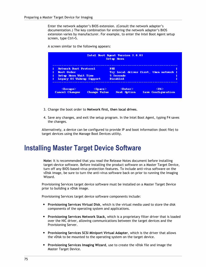
Enter the network adapter’s BIOS extension. (Consult the network adapter’sdocumentation.) The key combination for entering the network adapter’s BIOSextension varies by manufacturer. For example, to enter the Intel Boot Agent setupscreen, type Ctrl+S.
A screen similar to the following appears:
3. Change the boot order to Network first, then local drives.
4. Save any changes, and exit the setup program. In the Intel Boot Agent, typing F4 savesthe changes.
Alternatively, a device can be configured to provide IP and boot information (boot file) totarget devices using the Manage Boot Devices utility.
Installing Master Target Device SoftwareNote: It is recommended that you read the Release Notes document before installingtarget-device software. Before installing the product software on a Master Target Device,turn off any BIOS-based-virus protection features. To include anti-virus software on thevDisk image, be sure to turn the anti-virus software back on prior to running the ImagingWizard.
Provisioning Services target device software must be installed on a Master Target Deviceprior to building a vDisk image.
Provisioning Services target device software components include:
● Provisioning Services Virtual Disk, which is the virtual media used to store the diskcomponents of the operating system and applications.
● Provisioning Services Network Stack, which is a proprietary filter driver that is loadedover the NIC driver, allowing communications between the target devices and theProvisioning Server.
● Provisioning Services SCSI Miniport Virtual Adapter, which is the driver that allowsthe vDisk to be mounted to the operating system on the target device.
● Provisioning Services Imaging Wizard, use to create the vDisk file and image theMaster Target Device.
Preparing a Master Target Device for Imaging
75

● Virtual Disk Status Tray Utility, to provide general vDisk status and statisticalinformation. This utility includes a help system.
● Target Device Optimizer Utility, used to change target device setting to improveperformance.
Provisioning Services target device software is available for 32-bit and 64-bit Windowsoperating systems.
Installing Provisioning Services Target DeviceSoftware on a Windows Device
1. Boot the Master Target Device from the local hard disk.
2. Verify that all applications on the device are closed.
3. Double-click on the appropriate installer. The product installation window appears.
4. On the Welcome dialog that displays, click Next, scroll down to the end, then acceptthe terms of the license agreement.
5. Click Next to continue, the Customer Information dialog appears.
6. Type your user name and organization name in the appropriate text boxes.
7. Select the appropriate install user option. The option you select depends on if thisapplication will be shared by users on this computer, or if only the user associated withthis computer should have access to it.
8. Click Next, the Destination Folder dialog appears.
9. Click Next to install the target device to the default folder (C:\ProgramFiles\Citrix\Provisioning Services). Optionally, click Change, then either enter thefolder name or navigate to the appropriate folder, and then click Next, then clickInstall. The installation status information displays in the dialog.
Note: The installation process may take several minutes. While the installationprocess is running, you can click Cancel to cancel the installation and roll-back anysystem modifications. Close any Windows Logo messages that appear.
10. The 'Installation Wizard Completed' message displays in the dialog when thecomponents and options have successfully been installed. Close the wizard window. Ifboth .NET 3.0 SP1 or newer is installed and Windows Automount is enabled, the ImagingWizard will start automatically by default (for details, refer to Image Wizard).
Note: If a Windows reboot request message displays before the imaging processcompletes, ignore the request until imaging completes successfully.
11. Reboot the device after successfully installing product software and building the vDiskimage.
Preparing a Master Target Device for Imaging
76

77
Creating vDisks Automatically
A vDisk image can be created automatically using the Using the Imaging Wizard.
78
Using the Imaging Wizard to Create aNew vDisk
Use the Imaging Wizard to automatically create the base vDisk image from a master targetdevice.
Prerequisites
● Enable Windows Automount on Windows Server operating systems.
● Disable Windows Autoplay.
● Verify adequate free space exists in the vDisk store, which is approximately 101% ofused space on the source volumes.
● Make note of which NIC(s) the master target device was bound to when the ProvisioningServices software was installed on the target device. This information is necessaryduring the imaging process.
Note: If a Windows reboot request message displays before the imaging processcompletes, ignore the request until imaging completes successfully.
Imaging
The Imaging Wizard prompts for information that allows for connecting to the farm as wellas information necessary to set the appropriate credentials/Active Directory and licensinginformation to apply to this particular vDisk.
1. From the master target device's Windows Start menu, select Citrix>ProvisioningServices>Imaging Wizard. The wizard's Welcome page appears.
2. Click Next. The Connect to Farm page appears.
3. Enter the name or IP address of a Provisioning Server within the farm to connect to andthe port to use to make that connection.
4. Use the Windows credentials (default), or enter different credentials, then click Next.If using Active Directory, enter the appropriate password information.
5. On the Microsoft Volume Licensing page, select the volume license option to use fortarget devices or select None if volume licensing is not being used:
● None
● Key Management Service (KMS)
Note: Additional steps are required to implement KMS licensing after the vDiskimage is created. Refer to Managing Microsoft KMS Volume Licensing in theAdministrator's Guide for details.
● Multiple Activation Key (MAK)
Note: For information on managing MAK Licensing refer to Activating MicrosoftMAK Volume Licensing in the Administrator's Guide.
6. Select to create a new vDisk (default), or use an existing vDisk by entering that vDisksname, then click Next.
7. If the create new vDisk option was selected, the New vDisk dialog displays.
a. Enter a name for the vDisk
b. Select the Store where this vDisk will reside
c. Select the vDisk format from the appropriate drop-down menus. If the VHD formatis Dynamic, from the VHD block size drop-down, select the block size as either 2MB or 16 MB.
d. Click Next, then define volume sizes on the Configure Image Volumes page.8. Click Next The Add Target Device page appears.
9. Select the target device name, the MAC address associated with one of the NICs thatwas selected when the target device software was installed on the master targetdevice, and the collection to add this device to. Click Next. If the target device isalready a member of the farm, the Existing Target Devices page appears.
10. Click Next. Summary of Farm Changes appears.
11. Optional. Select to optimize the vDisk for use with Provisioning Services.
12. Verify all changes, then click Finish. A confirmation message displays.
13. Click Yes on the confirmation message to start the imaging process.
Using the Imaging Wizard to Create a New vDisk
79

80
Assigning vDisks to Target Devices
A vDisk can be assigned to a single target device or to all devices within a target devicecollection. If a target device has more than one vDisk assigned to it, a list of vdisks displaysat boot time allowing the user to select the appropriate vDisk to boot.
Note: If one or more versions exist for a vDisk, the version target devices use inProduction is either the highest numbered production version or an override version. Fordetails refer to 'Accessing a vDisk Version' in the Administrator's Guide. For Maintenanceand Test devices, the State of any non-production versions are labeled.
Assigning vDisks to a target device
vDisks can be assigned to a single target device using:
● Drag-and-drop
● Target Device Properties dialog
Note: A vDisk cannot be assigned to a target device using drag-and-drop if that targetdevice was assigned a personal vDisks using the XenDesktop Wizard. A message dialogdisplays if a vDisk is dragged and dropped onto a collection that contains one or moretarget devices that use personal vDisks. The dialog provides the option to continue byacknowledging that the vDisk being assigned will only be assigned to those devices thatare not currently assigned a personal vDisk. Also, target devices that use personal vDiskscannot inherit the properties of a target device that doesn't use a personal vDisk(copy/paste).
To assign a vDisk, using drag-and-drop, to one or all target devices within a collection:
1. In the Console tree, expand the vDisk Pool within a given site or expand Stores todisplay the vDisk to be assigned in the right pane of the window.
2. Left-click and hold the mouse on the vDisk, then drag and drop it onto the target deviceor onto the collection.
To assign one or more vDisks to a single target device from the Target Device Propertiesdialog:
1. In the Console tree, expand the Device Collections folder, then click on the collectionfolder where this target device is a member. The target device displays in the detailspane.
2. Right-click on the target device, then select Properties. The Target Device Propertiesdialog appears.
3. On the General tab, select the boot method that this target device should use from theBoot from drop-down menu options.

4. On the vDisks tab, select the Add button within the vDisk for this Device section. TheAssign vDisks dialog appears.
5. To locate vDisks to assign to this target device, select a specific store or server underthe Filter options, or accept the default settings, which includes All Stores and AllServers.
6. In the Select the desired vDisks list, highlight the vDisk(s) to assign, then click OK,then OK again to close the Target Device Properties dialog.
Assigning vDisks to Target Devices
81
82
Uninstalling Product Software
Removing the software from your system requires that you uninstall both the ProvisioningServer and target device components.
Uninstalling the Provisioning Services1. On the Provisioning Server, open the system’s Control Panel. From the Windows Start
menu, select Settings, and then click Control Panel.
2. Double click on the Add/Remove Programs icon.
3. Use Add/Remove Programs from the control panel to uninstall the product software.
Uninstalling Windows Target Device Software1. Set the system BIOS to boot from the original hard drive.
2. Re-boot the target device directly from the hard drive.
3. On the target device, open the system’s Control Panel.
4. Double-click on the Add>Remove Programs icon.
5. Use Add>Remove Programs from the control panel to uninstall the product software.
Uninstalling the Console1. On a machine in which the Console is installed, open the system’s Control Panel. From
the Windows Start menu, select Settings, and then click Control Panel.
2. Double click on the Add/Remove Programs icon.
3. Use Add/Remove Programs from the control panel to uninstall the product software.
83
Installing and Configuring EmbeddedTarget Devices
Using the Provisioning Services components described in this chapter, it is possible to createWindows XP Embedded operating system images that can boot from a vDisk.
Note: This feature is for Windows XP Embedded developers. This document assumes thatyou are familiar with the Microsoft Windows Embedded Studio tools including TargetDesigner and the Component Database Manager. For more information on the MicrosoftWindows Embedded tools, please refer to the documentation provided with the MicrosoftWindows Embedded Studio.
Embedded Target Device consists of the following components:
● ProvisioningservicesTargetDeviceSupport.sld - The Server Level Definition (SLD) filedefines the components that will be incorporated into the Windows XP Embeddeddatabase for use in the XP Embedded operating systems.
● ProvisioningservicesRepository - Contains all of the files used in theProvisioningservicesTargetDeviceSupport.sld, including Provisioning Services’ driversand installation utilities. These files are included in an XP Embedded build containingProvisioning Services components.
84
System Requirements
● Windows XP Embedded with the latest service pack.
● In order to build Windows XP Embedded operating systems, Microsoft WindowsEmbedded Studio must first be installed.
● The target device must meet the Windows XP Embedded system requirements. It isrecommended that a Windows XP Embedded operating system be built first on thedesired embedded target device to ensure OS compatibility and to resolve any OSspecific issues (such as driver requirements).
● Each embedded target device must also meet the target device requirements outlinedin the Provisioning Services Installation Guide.
● A local drive must exist on a target system during the initial XP Embedded operatingsystem build process. This is necessary to allow Microsoft’s First Boot Agent to run andfinish your XP Embedded image setup. Once the image is complete and the XPEmbedded disk image has been copied to the vDisk on the Provision Server or on sharednetwork storage, the local disk can be removed (if desired).
● The maximum size of the vDisk is 2 terabytes.
85
Installing Embedded Target Devices
Installation of Embedded Target Device components is done through the ProvisioningServices Installation Wizard.
1. Close all Windows and Embedded Studio tools that may be open (Target Designerand/or Component Designer).
2. When the Provisioning Services Installation Wizard is run, components used to buildProvisioning Services into an XP Embedded operating system are installed by default.Run the Component Database Manager from the Microsoft Start menu.
3. Select Programs > Microsoft Windows Embedded Studio.
4. Select the Database tab, and then click the Import button.
5. On the Import SLD screen, point the SLD file field to theProvisioningservicesTargetDeviceSupport.sld in the destination directory created bythe Provisioning Services installation. Select the desired root destination (typicallythere is only one choice), and then click the Import button to start the importingprocess.
6. Exit the Component Database Manager.
The Embedded Target Device support components will now be available in Target Designerunder the Software: System: Network & Communication component group. The EmbeddedTarget Device support macro component causes all necessary Provisioning Services’components to be included during dependency checking.
86
Un-installing an Embedded Target DevicePackage
1. Select Start > Programs > Microsoft Windows Embedded Studio.
2. Select the Package tab.
3. Under Available Packages, select the Provisioning Services Embedded Target Devicepackage, then click the Delete Package button.
4. A Confirmation Delete Package dialog appears, displaying all Provisioning Servicescomponents. Check the Delete all Provisioning Services Database files option, andclick Yes.
5. Select the Group tab.
6. Under Available Dependency Groups, select Provisioning Services Component Group,then click the Delete Dependency Group button.
7. Go to Control Panel > Add/Remove Programs, select Provisioning Services, and clickChange/Remove to uninstall the program.
87
Windows XP Embedded Build Overview
To fully understand how Provisioning Services gets incorporated into a Windows XPEmbedded operating system, it is first necessary to understand how a Windows XPEmbedded operating system is built. The illustration below outlines the major phases of aWindows XP Embedded operating system build process.
Note: For more information on building an XP Embedded operating systems, refer to theWindows XP Embedded Platform documentation provided with the Windows EmbeddedStudio tools.
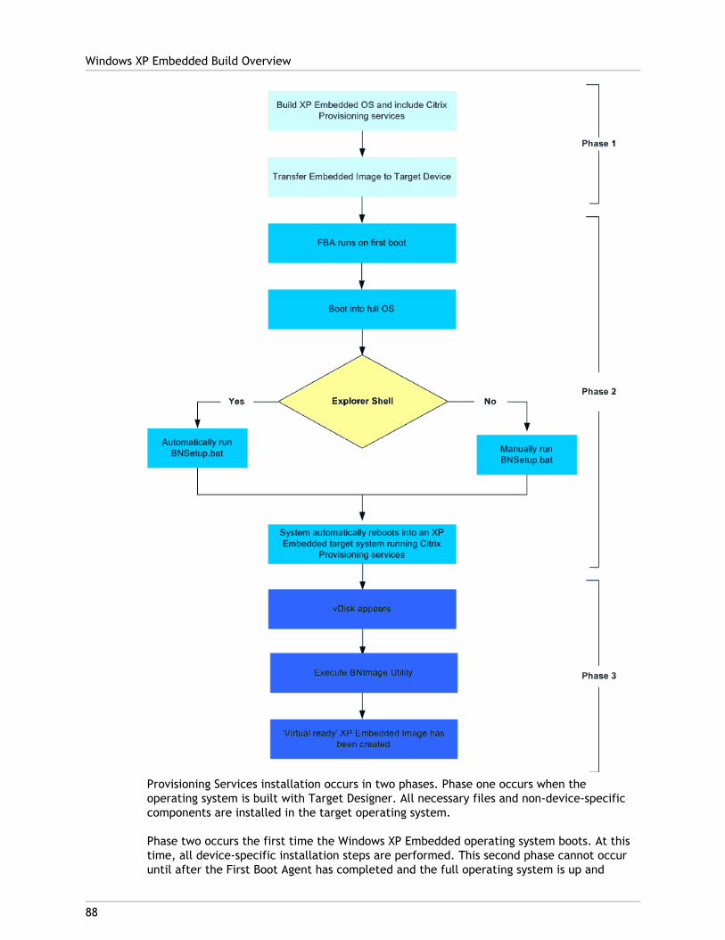
Provisioning Services installation occurs in two phases. Phase one occurs when theoperating system is built with Target Designer. All necessary files and non-device-specificcomponents are installed in the target operating system.
Phase two occurs the first time the Windows XP Embedded operating system boots. At thistime, all device-specific installation steps are performed. This second phase cannot occuruntil after the First Boot Agent has completed and the full operating system is up and
Windows XP Embedded Build Overview
88
running.
Note: If automatic installation was turned off to remove the dependence on the Explorershell component, it will be necessary to manually run the second phase of the installationprocess.
Once the XP Embedded Image with Provisioning Services support is fully up and running, itcan be imaged onto the embedded target device’s vDisk, after which the embedded targetdevice can be booted virtually.
Note: Provisioning Services require that at least one of the target systems have a physicaldisk for the creation of the initial XP Embedded operating system. After the operatingsystem is built and transferred to a vDisk, the target system’s physical disk can beremoved (if desired).
Windows XP Embedded Build Overview
89
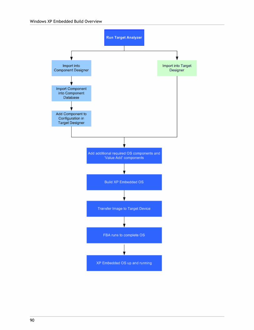
Windows XP Embedded Build Overview
90
91
Setting Up Embedded Target Devices
1. Transfer the built XP Embedded Image to the XP Embedded partition on the embeddedtarget device.
Note: The embedded target device must be configured to be bootable by XPEmbedded. To do this, run the BootPrep utility provided by Microsoft. For moreinformation on preparing target media to boot Windows XP Embedded, refer to“Building a Run-Time Image” in the Microsoft Windows XP Embedded Help.
2. Change your embedded target device’s BIOS setting to boot Network first, then bootthe embedded target device.
3. The XP Embedded Image will run through the Microsoft’s First Boot Agent (FBA), andcomplete the setup of the XP Embedded Operating system.
Note: By including the "Network Command Shell" component, the embedded targetdevice can be configured to use a static IP address from the command line (usingnetsh.exe). For more information on the Network Command Shell, refer to thefollowing web page:http://www.microsoft.com/technet/prodtechnol/winxppro/proddocs/netsh.asp
If the XP Embedded Image was created with Automatic installation turned off, or with ashell other than the Explorer Shell, Provisioning Services installation will have to becompleted manually. This can be done by running bnSetup.bat located in theC:\Program Files\Citrix\Provisioning Services directory. If the command promptcomponent (CMD - Windows Command Processor) was not included in the build, youmay have to run the commands in the batch file manually.
Note: The batch file BNSetup.bat will reboot your system.
4. Prepare your embedded target device. Once the XP Embedded Operating system iscompletely up and running an additional local disk appears on the device. This disk isthe vDisk associated with the embedded target device and is actually located on aProvisioning Server.
92
Upgrading a Provisioning Services Farm
Note: This release supports upgrading from 5.1 SP1, 5.1 SP2, 5.6, 5.6 SP1, 6.0.
Before attempting to upgrade a Provisioning Services farm:
● Select a maintenance window that has the least amount of traffic.
● Backup the Provisioning Services database.
● Backup all vDisks.
Upgrading from a previous Provisioning Services farm requires completing the followingprocedures:
1. Upgrade the first Provisioning Server, which upgrades the Provisioning Servicesdatabase. For details, refer to Upgrading the first Provisioning Server.
2. Upgrade the remaining Provisioning Servers within the farm. For details, refer toUpgrading remaining servers in the farm.
3. Upgrade Consoles. The Console is a separate executable that can be installed onupgraded servers (PVS_Console.exe or PVS_Console_64.exe). Remote Consoles can beupgraded at any time.
4. Upgrade vDisks using the Hyper-V method or the Reverse Imaging method. For details,refer to Upgrading vDisks Using Reverse Imaging or upgrade using Hyper-V. (Bothmethods include the steps necessary to upgrade the master target device software).
Caution: If upgrading a Provisioning Services vDisk within a XenDesktop deployment,the Provisioning Services master target device software must be upgraded beforeupgrading the XenDesktop VDA software.
Upgrade Utilities
The Upgrade Wizard facilitates the automation of the upgrade process, and includes thefollowing utilities:
● The UpgradeAgent.exe runs on the target device to upgrade previously installedproduct software.
● The UpgradeManager.exe runs on the Provisioning Server to control the upgrade processon the target device.
93
Upgrading the Database and ProvisioningServers
In a Provisioning Services farm, the database is upgraded at the same time that the firstProvisioning Server is upgraded. After the database and the first server in the farm areupgraded, the remaining servers within the farm can be upgraded.
Upgrading the Database and the First ProvisioningServer
Note: While upgrading the database on the first Provisioning Server, the Console maybecome temporarily unavailable for a short period of time. However, the farm continuesto run normally and any changes made during the database upgrade process arecaptured.
To upgrade:
1. Uninstall Provisioning Services software from a Provisioning Server in the farm (fordetails, refer to Uninstalling the Provisioning Services). This step also uninstalls theConsole.
2. To upgrade the server and database, run the new version of the server software on theserver.
Note: Alternatively, the database can be upgraded by running the upgrade script,which is produced by the database administrator using DbScript.exe. Running theupgrade script against the database eliminates the need to grant high-levelpermissions to Provisioning Services Administrators.
3. Install the Console on this server or on a server that will be used to manage the farm(for details on installing the Console, refer to Installing Provisioning Services ServerSoftware).
4. On the Configuration Wizard (if the wizard does not start automatically aftercompleting the product installation, start it now), select the option to join a farm thatis already configured. Running the wizard starts the services (for details, refer toConfiguration Wizard Tasks).
Upgrading Remaining Provisioning Servers in theFarm
Complete the same procedure that was performed on the first server on each of theremaining servers in the farm.

Note: The database upgrade is ignored because the database was upgraded when the firstserver was upgraded.
Upgrading the Database and Provisioning Servers
94
95
Upgrading vDisks by Re-imaging
Unlike traditional software packages, target devices can not be uninstalled while runningfrom a vDisk. vDisks can only be uninstalled while the operating system is running on aphysical hard disk so that the vDisk storage and network driver stack can be properly shutdown. The upgrade method that you choose will depend on your existing ProvisioningServices implementation and network requirements.
Upgrade vDisks re-imaging methods include:
● Automated Upgrade
● Manual Upgrade
While the manual upgrade method is the most reliable approach for all types of ProvisioningServices deployments, it is also the most labor intensive and time consuming of themethods.
A set of upgrade script utilities are included to streamline and automate the process.UpgradeAgent.exe and UpgradeManager.exe are the proxies to run on target devices andProvisioning Servers that were installed from previous product releases. This agentfacilitates the upgrade automation.
96
Automated Upgrade of vDisks
Note: The Automated Inline Upgrade method is being deprecated in this release.
Automated Rolling UpgradeThe automated rolling upgrade method converts vDisks to the current Provisioning ServervDisk format. This upgrade method does not require Provisioning Server deploymentdowntime, but it does require that a new dedicated Provisioning Server co-exist,side-by-side with a pervious version of the server.
Prerequisites:
● Both the previous version of the server and the new server are dedicated machines.
● The vDisk is from a previous version and has not been upgraded.
● The vDisk can boot from a previous version of the server.
● If both the previous and new versions of the servers are on the same network subnet,there should be only one PXE/TFTP service on the network.
Upgrading using the automated rolling upgrade process
On existing Provisioning Servers:
1. Change the target device’s vDisk to Private Image Mode, then PXE boot the targetdevice from that vDisk.
2. The Upgrade Manager requires RPC communication over the network. If there is afirewall on this server, set firewall to allow TCP port 6901.
On the new Provisioning Server:
1. Create a new vDisk with the same name, but of equal or larger size than the originalvDisk. Preformat the new vDisk by mounting it from the Provisioning Server Console,formatting it, and then unmounting it.
2. The Upgrade Manager requires RPC communication over the network. If there is afirewall on this server, set firewall to allow TCP port 6901. Do not turn on DHCP/PXEservices if this server is on the same network subnet as previous servers.
On the Master Target Device:
1. Depending on the target device platform, run either: PVS_UpgradeWizard.exe orPVS_UpgradeWizard_x64.exe.
2. Copy the matching version of the UpgradeManager.exe to the product installationdirectory.
3. Run Upgrade Manager on the Provisioning Server to be upgraded.
4. Copy UpgradeManager.exe to the new Provisioning Server installation directory.
5. Run UpgradeManager.exe on the new Provisioning Server.
6. Specify a local account with Administrator privileges to AutoLogon. This local accountcan not have empty password.
7. Specify a partition to which reverse imaging clones data. The original hard drive, whichthe vDisk was cloned from, is recommended. If this is a new hard drive, follow themanual upgrade procedure to initialize the hard drive.
8. Specify the previous Provisioning Server IP address, and a user account and password toconnect to UpgradeManager.exe. This account cannot have an empty password.
9. Specify the newer Provisioning Server IP address, and a user account and password toconnect to UpgradeManager.exe. This account cannot have an empty password.
10. Click OK and the UpgradeConfig performs a sanity check on various parameters. Ifeverything passes, you are prompted to reboot to start the upgrade process.
11. The upgrade script automates the steps performed during the Manual Upgradeprocedure. The machine reboots several times during the process, and then displays amessage when the upgrade has completed successfully. The script pauses and promptsyou after the reverse imaging and uninstallation steps. This is the time to switch thetarget device to the new Provisioning Server network.
● If both the previous and new Provisioning Servers are on the same network, turn offPXE and TFTP services on the previous Provisioning Server, then turn on PXE andTFTP services on the new Provisioning Server. Alternatively, use DHCP Reservationto create a exception for this target device and change DHCP option 66 Boot ServerHost Name to point to the new Provisioning Server.
● If the servers are on different networks, now is the time to swap the network cableto connect the target device to the new network.
12. After all vDisks have been upgraded, setup the PXE and TFTP services on the newProvisioning Server permanently, to serve new target devices.
Automated Upgrade of vDisks
97
98
Upgrading vDisks Manually
This section describes how to upgrade Provisioning Server vDisks manually.
Use the manual upgrade as a universal approach to upgrading vDisks, or if any of thefollowing are true:
● The vDisk has gone through a number of modifications in Private Image mode
● The original hard drive is no longer available
Some of the imaging tasks performed during a manual upgrade are automated by theUpgrade script that is used in the Automated Upgrade method (for details on theAutomated method, refer to Automated Upgrade of vDisks. The manual upgrade methodincludes completing the tasks defined in Image Back to Master Target Devices Hard Drive.
99
Image Back to Master Target DevicesHard Drive
There are two procedures that allow you to image a vDisk back to a hard drive. Theprocedure you select depends on the state of the disk drive you are imaging to. Select oneof the following procedures:
● Image back to the original hard drive from which the vDisk was created
Use the original hard drive from which the vDisk was created (recommended method).
● Image back using an unformatted, uninitialized hard-disk drive
Use an unformatted, uninitialized hard-disk drive.
Image Back to the Original Hard Drive from Which thevDisk was Created
1. Boot from the vDisk in Private or Shared Image Mode.
2. From Windows Administrative Tools, select the Computer Management menu option.The Computer Management window appears.
3. In the tree, under Storage, select Disk Management.
4. Note the partition letter of the active partition of the original hard disk. If new, formatthe disk before continuing.
5. Run the Image Builder utility on the target device. This utility is located at \ProgramFiles\Citrix\Provisioning Services\BNImage.exe
6. Specify the drive letter of the newly created partition (or the original boot HDDpartition) as the Destination Drive. The destination drive should point to the vDisk firstpartition by default.
7. Proceed cloning the hard drive image to the vDisk Destination Drive.
8. To connect the vDisk to the Provisioning Server, from the Console, set the target deviceto boot from the hard drive, then PXE boot the target device. If this step is notcompletely properly, the Provisioning Server will not be able to connect with the vDisk
9. Uninstall the product software (for details, refer to Uninstall Product Software) .
Image back using an unformatted, uninitializedhard-disk drive
1. Boot from the vDisk in Private Image Mode.
2. From Windows Administrative Tools, select the Computer Management menu option.The Computer Management window appears.
3. In the tree, under Storage, select Disk Management.
4. Create a new primary partition, as the first partition, assign a drive letter to it, andthen format the partition.
5. Right-click on the newly created partition, then choose Mark Partition as Active.
6. Delete the boot.ini.hdisk file from the root of the vDisk.
7. Run the Image Builder utility on the target device. This utility is located at \ProgramFiles\Citrix\Provisioning Services\BNImage.exe.
8. Specify the drive letter of the newly created partition (or the original boot HDDpartition) as the Destination Drive. The destination drive should point to the vDisk firstpartition by default.
9. Proceed cloning the hard drive image to the vDisk Destination Drive.
10. To connect the vDisk to the Provisioning Server, from the Console, set the target deviceto boot from the hard drive, then PXE boot the target device. If this step is notcompletely properly, the Provisioning Server will not be able to connect with the vDisk.
11. Uninstall the product software (for details, refer to Uninstall Product Software).
Install Master Target Device SoftwareComplete the following steps to install the latest product software on the Master TargetDevice.
1. Run the new Provisioning Server Target Device installer on the target device.
2. PXE boot the target device.
Imaging the Hard DriveComplete the following steps to image the target device’s hard drive on to the vDisk file:
1. Run the Image Builder utility on the target device. This utility is located at \ProgramFiles\Citrix\Provisioning Services\BNImage.exe.
Image Back to Master Target Devices Hard Drive
100
2. Specify the drive letter of the newly created partition (or the original boot HDDpartition) as the Destination Drive. The destination drive should point to the vDisk firstpartition by default.
3. Proceed cloning the hard drive image to the vDisk Destination Drive.
Boot from the vDiskUsing the Console, set the target device on the Provisioning Server to boot from vDisk first,then reboot the target device. The new target device should now be running the new vDiskimage.
Image Back to Master Target Devices Hard Drive
101
102
Upgrading vDisks using Hyper-V
Before upgrading using Hyper-v, review the following requirements:
● Hyper-V must be installed (Hyper-V does not need to be installed on the ProvisioningServer).
● General Hyper-V knowledge.
This section describes how to upgrade Provisioning Server vDisks using Microsoft Hyper-V asthe mechanism to install new versions of the Provisioning Service drivers and other targetdevice components. Using this method, neither physical media nor imaging and reimaging isrequired. This method greatly simplifies the upgrade process and reduces the number oftasks you must complete.
1. Un-install previously installed Provisioning Services server software.
2. Install newer version of Provisioning Services server software.
3. Copy the newly created or existing VHD file to the Hyper-V server.
4. Create a new virtual machine in the Hyper-V Manager.
5. During the creation steps, attach the existing newvDisk.vhd instead of using a new VHD.
6. Go into the properties of the newly created Hyper-V virtual machine (Action panel >Settings) and remove the Network adapter. Go to Add Hardware and add the LegacyNIC.
7. Go to the Legacy NIC and attach it to the physical system's NIC.
8. Boot the virtual machine.
9. Let the system install the new drivers, then reboot if prompted.
10. Un-install Provisioning Services target device software, then reboot.
11. Optional: Install Hyper-V's Integration Services. This is only necessary when theresulting VHD must be bootable in both physical and virtual systems. While the virtualmachine is on, go to Action, then choose Insert Integration Services set up disk andinstall.
12. Install Provisioning Services target device software.
13. Go to Provisioning Services installation directory (default is: C:\ProgramFiles\Citrix\Provisioning Services).
14. Start bindcfg.exe.
15. Choose to bind Provisioning Services to the inactive NIC (the physical NIC from theoriginal target device).
16. Shutdown the virtual machine.
17. Go to the virtual machine’s properties (Action panel > Settings), then set it to boot tothe legacy NIC first.
18. Transfer the VHD (newvDisk.vhd) back to the Provisioning Server.
19. From the Provisioning Service’s Console:
a. Add the VHD to the Provisioning Services database using the Add existing vDiskmenu option.
b. Add the Hyper-V virtual machine to the list of the target devices.
c. Associate the vDisk with the appropriate target devices.
d. Set the vDisk to Standard Image Mode20. Boot the physical target device (assuming this is set to PXE first), then the Hyper-V
virtual machine.
The original vDisk is now upgraded and a common image between the physical and virtualmachines has also been created.
Upgrading vDisks using Hyper-V
103
104
Managing Bootstrap Files and BootDevices
The following information is detailed in this chapter:
● Configuring the Bootstrap File From the Console
● Using the Manage Boot Devices Utility

105
Configuring the Bootstrap File From theConsole
For the Provisioning Server to start a target device, a boot file is downloaded by theProvisioning Services’s MBA or PXE-compliant boot ROM, when the device is turned on. Thisfile must be configured so that it contains the information needed to communicate with theProvisioning Servers. The Configure Bootstrap dialog is used to define the IP addresses forup to four Provisioning Servers in the boot file.
Note: For alternative boot methods, refer to Using the Manage Boot Devices Utility.
The Configure Bootstrap dialog field descriptions are as follows:
General Tab: Configure Bootstrap
Field Description
Bootstrap File The currently selected boot file displays. If you want toselect a different boot file to configure, click the Addbutton or Read Servers from Database button.
IP Settings The IP Address, Subnet Mask, Gateway, and Port for up tofour Provisioning Servers, which will perform loginprocessing.
Add button Click the Add button to add a new Provisioning Server tothe file. Up to four Provisioning Servers may be specifiedfor Provisioning Servers.
Edit button Highlight an existing Provisioning Server from the list,then click the Edit button to edit this server’s IP settings.
Remove button Select an existing Provisioning Server from the list, thenclick the Remove button to remove this server from thelist of available Provisioning Servers.
Move Up and Move Downbuttons
Select an existing Provisioning Server, and click to moveup or down in the list of Provisioning Servers. The order inwhich the Provisioning Servers appear in the listdetermines the order in which the Provisioning Serversare accessed should a server fail.
Read Servers fromDatabase button
To populate the boot file with the Stream Service IPsettings already configured in the database, click theRead Servers from Database button. This removes anyexisting settings before populating the list from thedatabase.
Target Device IP: Configure Bootstrap
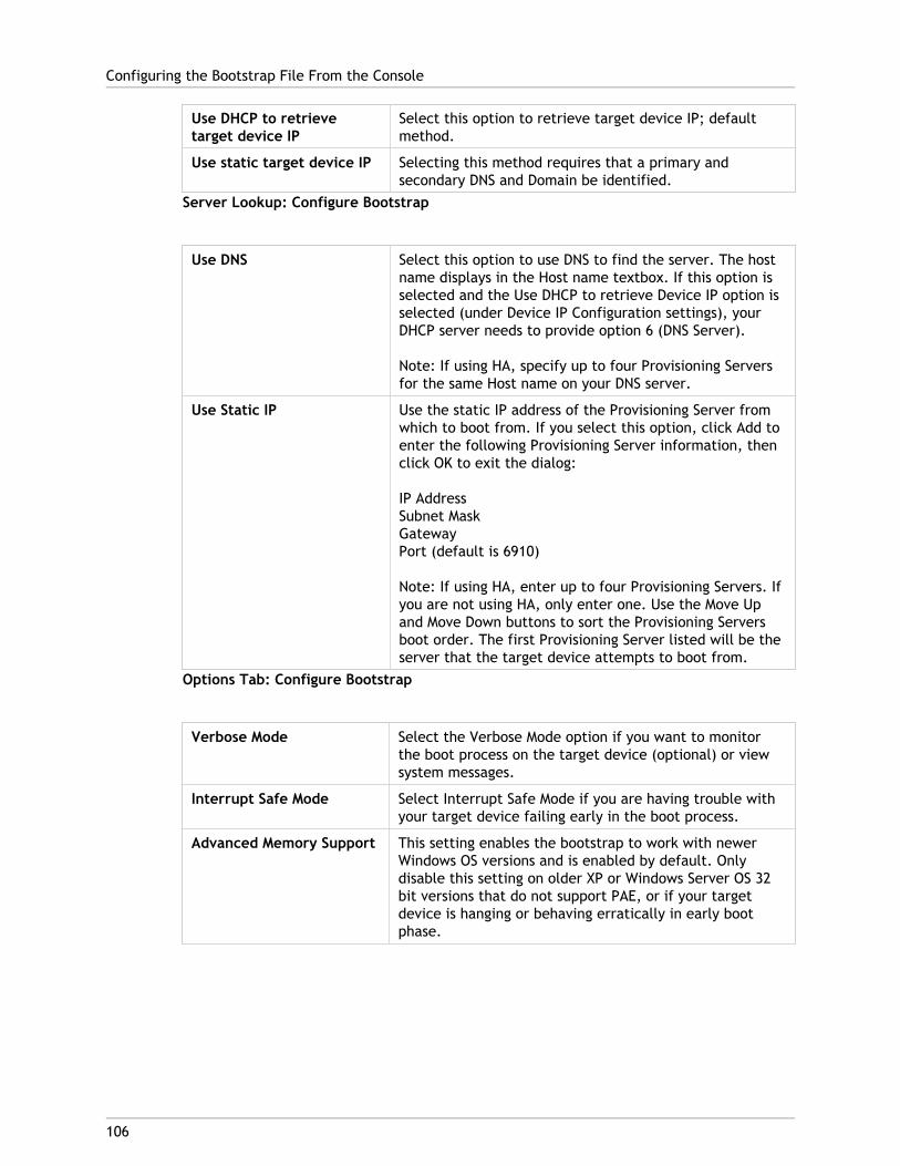
Use DHCP to retrievetarget device IP
Select this option to retrieve target device IP; defaultmethod.
Use static target device IP Selecting this method requires that a primary andsecondary DNS and Domain be identified.
Server Lookup: Configure Bootstrap
Use DNS Select this option to use DNS to find the server. The hostname displays in the Host name textbox. If this option isselected and the Use DHCP to retrieve Device IP option isselected (under Device IP Configuration settings), yourDHCP server needs to provide option 6 (DNS Server).
Note: If using HA, specify up to four Provisioning Serversfor the same Host name on your DNS server.
Use Static IP Use the static IP address of the Provisioning Server fromwhich to boot from. If you select this option, click Add toenter the following Provisioning Server information, thenclick OK to exit the dialog:
IP AddressSubnet MaskGatewayPort (default is 6910)
Note: If using HA, enter up to four Provisioning Servers. Ifyou are not using HA, only enter one. Use the Move Upand Move Down buttons to sort the Provisioning Serversboot order. The first Provisioning Server listed will be theserver that the target device attempts to boot from.
Options Tab: Configure Bootstrap
Verbose Mode Select the Verbose Mode option if you want to monitorthe boot process on the target device (optional) or viewsystem messages.
Interrupt Safe Mode Select Interrupt Safe Mode if you are having trouble withyour target device failing early in the boot process.
Advanced Memory Support This setting enables the bootstrap to work with newerWindows OS versions and is enabled by default. Onlydisable this setting on older XP or Windows Server OS 32bit versions that do not support PAE, or if your targetdevice is hanging or behaving erratically in early bootphase.
Configuring the Bootstrap File From the Console
106

Network Recovery Method Restore Network Connections — Selecting this optionresults in the target device attempting indefinitely torestore it's connection to the Provisioning Server.
Reboot to Hard Drive — (a hard drive must exist on thetarget device) Selecting this option instructs the targetdevice to perform a hardware reset to force a rebootafter failing to re-establish communications for a definednumber of seconds. The user determines the number ofseconds to wait before rebooting. Assuming the networkconnection can not be established, PXE will fail and thesystem will rebooot to the local hard drive. The defaultnumber of seconds is 50, to be compatible with HAconfigurations.
Login Polling Timeout Enter the time, in milliseconds, between retries whenpolling for Provisioning Servers. Each Provisioning Serveris sent a login request packet in sequence. The firstProvisioning Server that responds is used. In non-HAsystems, this time-out simply defines how often to retrythe single available Provisioning Server with the initiallogin request.
This time-out defines how quickly the round-robin routinewill switch from one Provisioning Server to the next intrying to find an active Provisioning Server. The validrange is from 1,000 to 60,000 milliseconds.
Login General Timeout Enter the time-out, in milliseconds, for all loginassociated packets, except the initial login pollingtime-out. This time-out is generally longer than thepolling time-out, because the Provisioning Server needstime to contact all associated servers, some of which maybe down and will require retries and time-outs from theProvisioning Server to the other Provisioning Servers todetermine if they are indeed online or not. The validrange is from 1,000 to 60,000 milliseconds.
Configuring the Bootstrap File From the Console
107

Configuring the Bootstrap File1. In the Console, highlight the Servers folder in the tree, or highlight a Provisioning
Server, then select Configure bootstrap from the Action menu. The ConfigureBootstrap dialog appears.
Select the boot file that was copied to the directory you selected during theProvisioning Server setup.
Important:
If a previous version of Provisioning services was installed on this server, you mustchange the default location from:
C:\Program Files\<CitrixorOEMname>\Provisioning Services
to:
C:\Documents and Settings\All Users\Application Data\<Citrix or OEMname>\Provisioningservices\Tftpboot
If the default is not changed, the bootstrap file can not be configured from the Consoleand target devices will fail to boot; receiving a ‘Missing TFTP’ error message.
Note: If you installed the Console on a separate machine, select the path of theremote Provisioning Server (which has boot services installed).
2. Click Read DB. When the Stream Service starts, it creates a record in the database withits own IP address. There is only one Stream Service option record per database. If theservice is bound to multiple IP addresses, multiple records appear in the database. TheRead DB function chooses only one IP address from each Provisioning Server. Thisfunction can also be used to populate the boot file with the Stream Service IP settingsalready configured in the database.
3. Choose from the following options:
● Select the Verbose Mode option if you want to monitor the boot process on thetarget device (optional). This enables system messaging on the target device.
● Select Interrupt Safe Mode if the target device hangs early in the boot process.
● Select Advanced Memory Support option to enable the bootstrap to work withnewer Windows OS versions (enabled by default). Only disable this setting on olderXP or Windows Server OS 32 bit versions that do not support PAE, or if your targetdevice is hanging or behaving erratically in early boot phase.
4. Select from the following Network Recovery Methods:
● Restore Network Connections - Selecting this option results in the target deviceattempting indefinitely to restore it's connection to the Provisioning Server.
● Reboot to Hard Drive - Selecting this option instructs the target device to perform a hardware reset to force a reboot after failing to re-establish communications for a defined number of seconds. The user determines the number of seconds to wait before rebooting. Assuming the network connection can not be established, PXE will fail and the system will reboot to the local hard drive. The default number of
Configuring the Bootstrap File From the Console
108

seconds is 50. Click the Browse button to search for and select the folder created inStep 1, or enter a full path or UNC name.
Note: If the partition containing the vDisks is formatted as a FAT file system, amessage displays a warning that this could result in sub-optimal performance. It isrecommended that NTFS be used to format the partition containing the vDisks. Do notchange the address in the Port field.
Caution: All boot services (PXE, TFTP) must be on the same NIC (IP). But the StreamService can be on a different NIC. The Stream Service allows you to bind to multipleIPs (NICs).
5. Configure the following:
Login Polling Timeout
Enter the time, in milliseconds, between retries when polling for servers. Each server issent a login request packet in sequence. The first server that responds is used. Thistime-out simply defines how often to retry the single available server with the initiallogin request. This time-out defines how quickly the round-robin routine will switchfrom one server to the next, in trying to find an active server. The valid range is from1,000 to 60,000 milliseconds.
Login General Timeout
Enter the time-out, in milliseconds, for all login associated packets, except the initiallogin polling time-out. The valid range is from 1,000 to 60,000 milliseconds.
6. Click OK to save your changes.
Configuring the Bootstrap File From the Console
109
110
Using the Manage Boot Devices Utility
The Manage Boot Devices Utility provides an optional method for providing IP and bootinformation (boot device) to target devices; as an alternative to using the traditional DHCP,PXE, and TFTP methods. Using this method, when the target device starts, it obtains theboot information directly from the boot device. With this information, the target device isable to locate, communicate, and boot from the appropriate Provisioning Server. After theuser is authenticated, the Provisioning Server provides the target device with its vDiskimage.
Supported Boot Devices
The following boot devices are supported in this release:
Note: The Boot Device Management utility is not supported on operating systems olderthan, and including, Windows 2000. Wireless NICs are not supported.
● USB
● CD-ROM (ISO)
● Hard Disk Partition
Caution:
When an entire hard drive is selected as boot device, all existing disk partitions are erasedand re-created with a single active partition. The targeted partition is reserved as a bootdevice and cannot be used by the operating system or data.
When a hard disk partition is selected as boot device, the selected disk partition data isdeleted and set as an active partition. This active partition becomes the boot device.
Boot devices are configured using the Boot Device Management utility. The Manage BootDevices utility is structured as a wizard-like application, which enables the user to quicklyprogram boot devices.
After installing the boot device, complete the procedures that follow.
Configuring Boot Devices
● The vDisk must already be formatted and ready before the BDM.exe is run.
● If using the target device hard disk drive as the boot device, copy BDM. exe from theproduct installation directory on the server, into the product installation directory onthe target device.
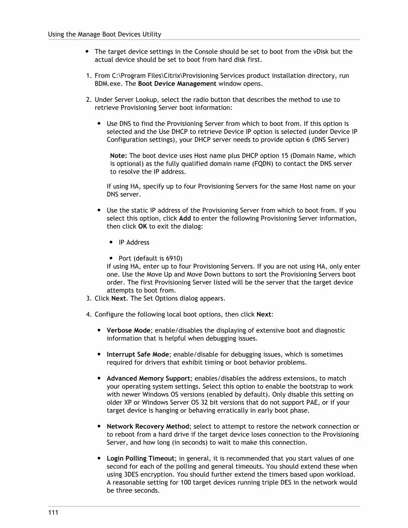
● The target device settings in the Console should be set to boot from the vDisk but theactual device should be set to boot from hard disk first.
1. From C:\Program Files\Citrix\Provisioning Services product installation directory, runBDM.exe. The Boot Device Management window opens.
2. Under Server Lookup, select the radio button that describes the method to use toretrieve Provisioning Server boot information:
● Use DNS to find the Provisioning Server from which to boot from. If this option isselected and the Use DHCP to retrieve Device IP option is selected (under Device IPConfiguration settings), your DHCP server needs to provide option 6 (DNS Server)
Note: The boot device uses Host name plus DHCP option 15 (Domain Name, whichis optional) as the fully qualified domain name (FQDN) to contact the DNS serverto resolve the IP address.
If using HA, specify up to four Provisioning Servers for the same Host name on yourDNS server.
● Use the static IP address of the Provisioning Server from which to boot from. If youselect this option, click Add to enter the following Provisioning Server information,then click OK to exit the dialog:
● IP Address
● Port (default is 6910)If using HA, enter up to four Provisioning Servers. If you are not using HA, only enterone. Use the Move Up and Move Down buttons to sort the Provisioning Servers bootorder. The first Provisioning Server listed will be the server that the target deviceattempts to boot from.
3. Click Next. The Set Options dialog appears.
4. Configure the following local boot options, then click Next:
● Verbose Mode; enable/disables the displaying of extensive boot and diagnosticinformation that is helpful when debugging issues.
● Interrupt Safe Mode; enable/disable for debugging issues, which is sometimesrequired for drivers that exhibit timing or boot behavior problems.
● Advanced Memory Support; enables/disables the address extensions, to matchyour operating system settings. Select this option to enable the bootstrap to workwith newer Windows OS versions (enabled by default). Only disable this setting onolder XP or Windows Server OS 32 bit versions that do not support PAE, or if yourtarget device is hanging or behaving erratically in early boot phase.
● Network Recovery Method; select to attempt to restore the network connection orto reboot from a hard drive if the target device loses connection to the ProvisioningServer, and how long (in seconds) to wait to make this connection.
● Login Polling Timeout; in general, it is recommended that you start values of onesecond for each of the polling and general timeouts. You should extend these whenusing 3DES encryption. You should further extend the timers based upon workload.A reasonable setting for 100 target devices running triple DES in the network wouldbe three seconds.
Using the Manage Boot Devices Utility
111

● Login General Timeout; a reasonable setting for 100 target devices running tripleDES in the network would be ten Seconds for the General Timeout.
5. On the Burn the Boot Device dialog, configure the target device IP. If the Use DNS tofind the Server option is selected and your DHCP service does not provide option 6(DNS Server), then enter the following required information (note that the server namemust be less than 16 characters length and the domain name less than 48 characters inlength):
● Primary DNS Server Address
● Secondary DNS Server Address
● Domain Name6. Configure the Boot Deviceproperties.
● Add an active boot partition . Check this option to add a boot partition. Note: Aboot partition is required if booting from the device's hard drive (for example, whenselecting a XENPVDISK boot device with small partition or partition offset).
● Select the boot device from the list of devices.If a partition offset size is set, a confirmation message displays to confirm thedestination size. Type Yes (case sensitive) to continue.
7. If applicable, configure Media Properties.
8. Click Burn. A message appears to acknowledge that the boot device was successfullycreated. If selecting ISO format, use your CD burning software to burn the ISO image.
9. Click Exit to close the utility.
10. Boot the target device and enter the BIOS Setup. Under the Boot Sequence, move theboot device to the top of the list of bootable devices. Save the change, then boot thetarget device.
After the boot device is programmed, a target device boot sequence can be configuredusing the Console’s Target Device Disk Properties dialog. These boot behaviors are usedafter a target device connects to a Provisioning Server. The Console allows multiple vDiskimages to be assigned to a target device. The way in which these vDisks boot depends uponthe selected boot behavior.
When configuring the BIOS to work with the boot device (either USB or ISO image), it isimperative that the NIC PXE option is enabled. The PXE boot option is required in order forthe NIC Option ROM to stay resident in memory during the pre-boot process. This way, UNDIwill be available to the boot device to properly initialize the NIC. Otherwise, the "API notfound" message would be displayed by the boot device.
Using the Manage Boot Devices Utility
112
113
Provisioning Services Administration
● Provisioning Services Product Overview
● Product Technology Overview
● Using the Console
● Managing Farms
● Managing Sites
● Managing Administrative Roles
● Managing Stores
● Managing Provisioning Servers
● Managing vDisks
● Managing Target Devices
● Managing Device Collections
● Managing User Assigned vDisks
● Managing Views
● Managing for Highly Available Implementations
● Configuring vDisks for Active Directory Management
● Managing Network Components
● Managing Printers
● Logging
● Auditing
● Configuring the BIOS Embedded Bootstrap
114
Using the Console
Use the Provisioning Services Console to manage components within a Provisioning Servicesfarm. The Console can be installed on any machine that can access the farm.
For more information on the Console refer to:
● Starting the Console
● Console Window
● Performing Tasks in the Console
115
Starting the Console
Before starting the Console, make sure that the Stream Service is started and running onthe Provisioning Server. (After the Configuration Wizard runs, the Stream Service startsautomatically).
To start the Console
From the Start menu, select:
All Programs>Citrix>Provisioning Services>Citrix Provisioning Console
The Console’s main window appears.
Note: To connect to a farm refer to Farm Tasks.
116
Understanding the Console Window
On the main Console window, you can perform tasks necessary when setting up, modifying,tracking, deleting, and defining the relationships among vDisks, target devices, andProvisioning Servers within your network.
For details on using various Console components, refer to:
● Using the Console Tree
● Basic Tree Hierarchy
● Using the Details View
● Common Menu Options
Using the Console TreeThe tree is located in the left pane of the Console window. The tree shows a hierarchicalview of your network environment and managed objects within your network. What displaysin the Details view depends on the object you have selected in the tree and your user role.
In the tree, click + to expand an managed object node, or click - to collapse the node.
Basic Tree HierarchyFarm administrators can create new sites, views, and stores within the farm. The farm-leveltree is organized as follows:
● Farm
● Sites
● Views
● StoresSite administrators generally manage those objects within sites to which they haveprivileges. Site’s contain Provisioning Servers, a vDisk Pool, device collections and views.The site-level tree is organized as follows:
● Site
● Servers
● Device Collections

● vDisk Pool
● vDisk Update Management
● Views
Using the Details ViewThe right-hand pane of the Console window contains the details view. This view providesinformation about the object selected in the tree, in table format. The types of objectsthat display in the view include Provisioning Servers, target devices, and vDisks. For moredetailed information, right-click on the object, then select the Properties menu.
The tables that display in the details view can be sorted in ascending and descending order.
In the Console, the objects that display and the tasks that you can perform are dependanton the role that you are assigned.
Common Action Menu OptionsThe following menu options are common to most objects in the Console:
New Window From Here
To open a new Console window, right-click on an object in the tree or in the details pane,then select the New Window from Here menu option. A new Console window opens. It maybe necessary to minimize the window to view and toggle between one or more windows.
Refresh
To refresh information in the Console, right-click a folder, icon, or object, then selectRefresh.
Export List
1. To export table information from the details pane to a text or comma delimited file,select Export from the Action menu.
2. Select the location where this file should be saved inSave in:
3. Type or select the file name in the File name textbox.
4. Select the file type from and Save as text boxes.
5. Click Save to save the file.
Help
Select an object in the Console, then select Help from the Action menu to displayinformation about that object.
Understanding the Console Window
117

View Options
To customize a Console view:
1. Select View, then select either Add/Remove Columns... or Customize....
2. If you selected:
● Add/Remove Columns..., use the Add and Remove buttons to select whichcolumns to display.
● Customize..., select the check box next to each MMC and Snap-in view option thatshould display in the Console window.
3. Click OK. The Console view refreshes to display the view options selected.
Understanding the Console Window
118
119
Performing Tasks in the Console
Use the following Console menus and features to perform tasks:
Note: Use the Ctrl key to make non-continuous selections or the Shift key to makecontinuous selections.
● Action
● Right-click
● Drag and Drop
● Copy and Paste
● Views
Action menuSelect object-related tasks from the Action menu such as; boot, restart, send message,view properties, copy or paste properties. For a complete list of tasks, refer to thatobject’s management chapter within this guide.
Right-click (context) MenuRight-click a managed object(s) to select object-related tasks. For a complete list of tasks,refer to that object’s management chapter within this guide.
Using Drag-and-DropUsing the Drag-and-Drop feature, you can quickly perform several common Console taskssuch as:
● Move target devices by dragging them from one device collection, and dropping themon another device collection within the same site.
● Assign a vDisk to all target devices within a collection by dragging the vDisk anddropping it on the collection. The vDisk and the collection must be in the same site.(The new vDisk assignment replaces any previous vDisk assignments for that collection).
● Add a target device to a view by dragging the device, then dropping it on the view inConsole’s tree.
● Drag a Provisioning Server from one Site, then drop it into another site. (Any vDisksassignments that were specific to this server and any store information will be lost.).
Using Copy and PasteSelect an object in the Console window, then use the Copy and Paste right-click menuoptions to quickly copy one or more properties of a vDisk, Provisioning Server, or targetdevice, to one or more existing vDisks, Provisioning Servers, or target devices.
To copy the properties of a one object type and paste those properties to multiple objectsof the same type:
1. In the tree or details pane, right-click the object which has the properties you want tocopy, then select Copy. The object-specific Copy dialog appears.
2. Place a check in the checkbox next to each of the object properties you want to copy,then click OK.
3. In the Console tree, expand the directory where the object exists so that those objectsdisplay in either the tree or details pane.
4. Right-click on the object(s) in the tree or details pane that you want to pasteproperties to, then select Paste.
Using ViewsCreate views containing target devices to display only those target devices that you arecurrently interested in viewing or performing tasks on. Adding target devices to a viewprovides a quick and easy way to perform a task on members of that view, such as:
● Boot
● Restart
● Shutdown
● Send message
Views can be created at the site level or at the farm level. To perform a task on membersof a view:
1. Right-click on views icon, then select the Create View... menu option. The ViewProperties dialog appears.
2. Type the name and a description of the new view in the appropriate text boxes, thenselect the Members tab.
3. To add target devices to this view, click the Add button. The Select Target Devicesdialog appears.
4. If you are creating the view at the farm level, select the site where the target devicesreside. If you are creating the view at the site level, the site information is alreadypopulated.
5. From the drop-down menu, select the device collection where the target devices to addare members.
Performing Tasks in the Console
120

6. Select from the list of target devices that display, then click OK.
7. If necessary, continue adding target devices from different device collections within asite.
8. Click the OK button to close the dialog.
For more information on views, refer to Managing Views.
Performing Tasks in the Console
121
122
Managing Farms
A farm represents the top level of a Provisioning Services infrastructure. Farms provide a“Farm Administrator” with a method of representing, defining, and managing logical groupsof Provisioning Services components into sites.
All sites within a farm share that farm’s Microsoft SQL database. A farm also includes aCitrix License Server, local or network shared storage, and collections of target devices.
To learn more about managing farms, refer to the follow sections:
● Configuring a New Farm
● Farm Tasks
● Farm Properties
123
Configuring the Farm
Run the Configuration Wizard on a Provisioning Server when creating a new farm, addingnew Provisioning Servers to an existing farm, or reconfiguring an existing ProvisioningServer.
When configuring a Provisioning Server, consider the following:
● All Provisioning Servers within a farm must share the same database to locate vDisks fortarget devices on shared storage devices within the farm. If that shared storage deviceis a Windows network share, refer to configuration information described in theAdministrator’s Guide, Managing Network Components section. If that shared storagedevice is a SAN, no additional configuration is necessary.
● To properly configure the network services, be sure that you understand networkservice options and settings.
Note: If all Provisioning Servers in the farm share the same configuration settings such assite and store information, consider Running the Configuration Wizard Silently.
Configuration Wizard SettingsBefore running the Configuration Wizard, be prepared to make the following selections:
Note: The Configuration Wizard can also be run silently on servers that share similarconfiguration settings. For details, refer to Running the Configuration Wizard Silently.
● Network Topology
● Identify the Farm
● Identify the Database
● Identify the Site
● License Server Settings
● Select Network Cards for the Stream Service
● Configure Bootstrap Server
Note: If errors occur during processing, the log is written to a ConfigWizard.log file,which is located at:
● C:\ProgramData\Citrix\Provisioning Services for 2008 and newer.

● C:\Documents and Settings\All Users\ApplicationData\Citrix\Provisioning Services for 2003.
Starting the Configuration WizardThe Configuration Wizard starts automatically after Provisioning Services software isinstalled. The wizard can also be started by selecting:
1. Start > All Programs > Citrix > Provisioning Services > Provisioning ServicesConfiguration Wizard
2. After starting the Configuration Wizard, click Next to begin the configuration tasks thatfollow.
Note: When running the Configuration Wizard, the tasks that appear depend on thenetwork service options that are selected and the purpose for running the wizard.
Network TopologyComplete the network configuration steps that follow.
1. Select the network service to provide IP addresses
Note: Use existing network services if possible. If for any reason existing networkservices can not be used, choose to install the network services that are madeavailable during the installation process.
To provide IP addresses to target devices, select from the following network serviceoptions:
● If the DHCP service is on this server, select the radio button next to one of thefollowing network services to use, then click Next:
● Microsoft DHCP
● Provisioning Services BOOTP service
● Other BOOTP or DHCP service● If the DHCP service is not on this server, select the radio button next to The
service is running on another computer, then click Next.2. Select the network service to provide PXE boot information
Each target device needs to download a boot file from a TFTP server.
Select the network service to provide target devices with PXE boot information:
● If you choose to use this Provisioning Server to deliver PXE boot information, selectThe service that runs on this computer, then select from either of the followingoptions, then click Next:
Configuring the Farm
124

● Microsoft DHCP (options 66 and 67)
● Provisioning Services PXE Service
● If Provisioning Services will not deliver PXE boot information, select Theinformation is provided by a service on another device option, then click Next.
Identify the FarmNote: When configuring the farm, the combination of the database name and farm namecannot exceed 54 characters. Exceeding this limitation may cause the farm name todisplay truncated in the Existing Farms screen.
1. Select from the following farm options:
● Farm is already configured
Select this option to reconfigure an existing farm, then continue on to the“Configure user account settings” procedure. This option only appears if a farmalready exists.
● Create farm
a. On the Farm Configuration dialog, select the Create Farm radio button tocreate a new farm, then click Next.
b. Use the Browse button to browse for existing SQL databases and instances inthe network, or type the database server name and instance. Optionally, entera TCP port number to use to communicate with this database server.
c. To enable database mirroring, enable the Specify database mirror failoverpartner option, then type or use the Browse button to identify the failoverdatabase server and instance names. Optionally, enter a TCP port number touse to communicate with this server.
Note: Refer to Database Mirroring in the Provisioning ServicesAdministrator's Guide for more information.
d. Click Next to continue on to the “Selecting the database location” procedure.● Join existing farm
a. On the Farm Configuration dialog, select the Join Existing Farm radio button toadd this Provisioning Server to an existing farm, then click Next.
b. Use the Browse button to browse for the appropriate SQL database andinstance within the network.
c. Select the farm name that displays by default, or scroll to select the farm tojoin.
Note: More than one farm can exist on a single server. This configuration iscommon in test implementations.
Configuring the Farm
125
d. To enable database mirroring, enable the Specify database mirror failoverpartner option, then type or use the Browse button to identify the failoverdatabase server and instance names. Optionally, enter a TCP port number touse to communicate with this server.
Note: Refer to Database Mirroring in the Provisioning ServicesAdministrator's Guide for more information.
e. Click Next.
f. Select from the following site options, then click Next:
● Existing Site: Select the site from the drop-down menu to join an existingsite.
● New Site: Create a site by typing the name of the new site and acollection.
Continue on to Configure user account settings procedure.
Identify the DatabaseOnly one database exists within a farm. To identify the database, complete the steps thatfollow.
1. Select the database location If the database server location and instance have not yetbeen selected, complete the following procedure.
a. On the Database Server dialog, click Browse to open the SQL Servers dialog.
b. From the list of SQL Servers, select the name of the server where this databaseexists and the instance to use (to use the default instance, SQLEXPRESS, leave theinstance name blank). In a test environment, this may be a staged database.
Note: When re-running the Configuration Wizard to add additional ProvisioningServers database entries, the Server Name and Instance Name text boxes arealready populated. By default, SQL Server Express installs as an instance named‘SQLEXPRESS’.
c. Click Next. If this is a new farm, continue on to the “Defining a Farm” procedure.2. To change the database to a new database
a. On the old database server, perform a backup of the database to a file.
b. On the new database server, restore the database from the backup file.
c. Run the Configuration Wizard on each Provisioning Server.
d. Select Join existing farm on the Farm Configuration dialog.
e. Enter the new database server and instance on the Database Server dialog.
f. Select the restored database on the Existing Farm dialog.
g. Select the site that the Server was previously a member of on the Site dialog.
Configuring the Farm
126

h. Click Next until the Configuration Wizard finishes.
3. Define a farm. Select the security group to use:
● Use Active Directory groups for security
Note: When selecting the Active Directory group to act as the Farm Administratorfrom the drop-down list, choices include any group the current user belongs to.This list includes Builtin groups, which are local to the current machine. Avoidusing these groups as administrators, except for test environments. Also, beaware that some group names may be misleading and appear to be Domaingroups, which are actually Local Domain groups. For example:ForestA.local/Builtin/Administrators.
● Use Windows groups for security4. Click Next.
Continue on to the“Selecting the license server” procedure.
Create a New Store for a New FarmA new store can be created and assigned to the Provisioning Server being configured:
Note: The Configuration Wizard only allows a server to create or join an existing store ifit is new to the database. If a server already exists in the database and it rejoins a farm,the Configuration Wizard may prompt the user to join a store or create a new store, butthe selection is ignored.
1. On the New Store page, name the new Store.
2. Browse or enter the default path (for example: C:\PVSStore) to use to access this store,then click Next. If an invalid path is selected, an error message appears. Re-enter avalid path, then continue. The default write cache location for the store is locatedunder the store path for example: C:\PVSStore\WriteCache.
Configuring the Farm
127

Identify the Site1. When joining an existing farm, identify the site where this Provisioning Server is to be a
member, by either creating a new site or selecting an existing site within the farm.When a site is created, a default target device collection is automatically created forthat site.
● Create a new site
a. On the Site page, enable the New Site radio button.
b. In the Site Name text box, type the new site name where this ProvisioningServer is to be a member.
c. In the Collection Name, accept the default collection, Collection, or create anew default collection name to associate with this Provisioning Server, thenclick Next.
● Select an existing site
a. On the Site page, enable the Existing Site radio button. (The default site nameis Site.)
b. Select the appropriate site from the drop-down list, then click Next.
c. Create a new store or select an existing store on the Store page, then clickNext.
Select the License ServerNote: When selecting the license server, ensure that all Provisioning Server’s in the farmare able to communicate with that server in order to get the appropriate productlicenses.
1. Enter the name (or IP address) and port number of the license server (default is 27000).The Provisioning Server must be able to communicate with the license server to get theappropriate product licenses.
2. Optionally, select the checkbox Validate license server version and communicationtoverify that the license server is able to communicate with this server and that theappropriate version of the license server is being used. If the server is not able tocommunicate with the license server, or the wrong version of the license server is beingused, an error message displays and does not allow you to proceed.
3. Click Next to continue on to the“Configure user account settings” procedure.
Configure User Account SettingsThe Stream and Soap services run under a user account.
1. On the User Account dialog, select the user account that the Stream and Soap serviceswill run under:
Configuring the Farm
128

● Specified user account (required when using a Windows Share; workgroup ordomain user account)
Type the user name, domain, and password information in the appropriate textboxes.
● Local system account (for use with SAN)
2. Select the checkbox next to the Configure the database for the account option, if youselected Specified user account, which adds the appropriate database roles(Datareader and Datawriter) for this user.
3. Click Next, then continue on to the“Selecting network cards for the Stream Service”procedure.
Select Network Cards for the Stream ServiceNote: If multiple network adapters are selected, they must be configured with the sameIP subnet address. For example: IP subnet: 100.100.10.x; IP subnet mask 255.255.255.0
1. Select the checkbox next to each of the network cards that the Stream Service can use.
2. Enter the base port number that will be used for network communications in the Firstcommunications port: text box.
Note: A minimum of 20 ports are required within the range. All Provisioning Serverswithin a farm must use the same port assignments.
3. Select the Soap Server port (default is 54321) to use for Console access, then clickNext.
Continue on to the “Selecting the bootstrap server” procedure.
Configure Bootstrap ServerComplete the steps that follow to identify the bootstrap server and configure the bootstrapfile location.
Note: Bootstrap configurations can be reconfigured by selecting the Configure Bootstrapoption from the Provisioning Services Action menu in the Console.
1. Select the bootstrap server. To use the TFTP service on this Provisioning Server:
a. Select the Use the TFTP Service option, then enter or browse for the boot file. Thedefault location is: C:\Documents and Settings\AllUsers\ProgramData\Citrix\Provisioning Services\Tftpboot
If a previous version of Provisioning Services was installed on this server, and thedefault location is:
C:\Program Files\Citrix\Provisioning Services\TftpBoot
Configuring the Farm
129
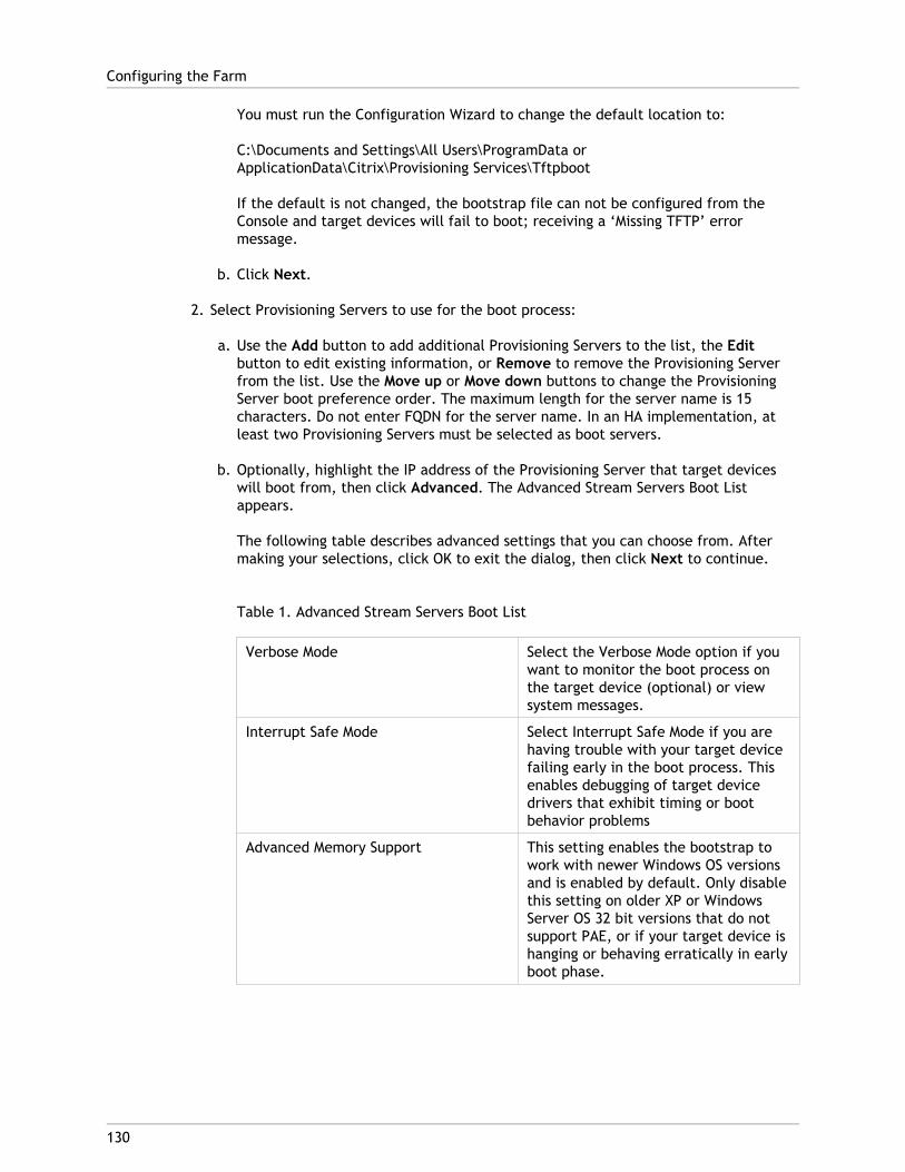
You must run the Configuration Wizard to change the default location to:
C:\Documents and Settings\All Users\ProgramData orApplicationData\Citrix\Provisioning Services\Tftpboot
If the default is not changed, the bootstrap file can not be configured from theConsole and target devices will fail to boot; receiving a ‘Missing TFTP’ errormessage.
b. Click Next.
2. Select Provisioning Servers to use for the boot process:
a. Use the Add button to add additional Provisioning Servers to the list, the Editbutton to edit existing information, or Remove to remove the Provisioning Serverfrom the list. Use the Move up or Move down buttons to change the ProvisioningServer boot preference order. The maximum length for the server name is 15characters. Do not enter FQDN for the server name. In an HA implementation, atleast two Provisioning Servers must be selected as boot servers.
b. Optionally, highlight the IP address of the Provisioning Server that target deviceswill boot from, then click Advanced. The Advanced Stream Servers Boot Listappears.
The following table describes advanced settings that you can choose from. Aftermaking your selections, click OK to exit the dialog, then click Next to continue.
Table 1. Advanced Stream Servers Boot List
Verbose Mode Select the Verbose Mode option if youwant to monitor the boot process onthe target device (optional) or viewsystem messages.
Interrupt Safe Mode Select Interrupt Safe Mode if you arehaving trouble with your target devicefailing early in the boot process. Thisenables debugging of target devicedrivers that exhibit timing or bootbehavior problems
Advanced Memory Support This setting enables the bootstrap towork with newer Windows OS versionsand is enabled by default. Only disablethis setting on older XP or WindowsServer OS 32 bit versions that do notsupport PAE, or if your target device ishanging or behaving erratically in earlyboot phase.
Configuring the Farm
130

Network Recovery Method Restore Network Connections—Selecting this option results in thetarget device attempting indefinitelyto restore it's connection to theProvisioning Server.
Note: Because the Seconds field doesnot apply, it becomes inactive whenthe Restore Network Connectionsoption is selected.
Reboot to Hard Drive— (a hard drivemust exist on the target device)Selecting this option instructs thetarget device to perform a hardwarereset to force a reboot after failing tore-establish communications for adefined number of seconds. The userdetermines the number of seconds towait before rebooting. Assuming thenetwork connection can not beestablished, PXE will fail and thesystem will reboot to the local harddrive. The default number of secondsis 50, to be compatible with HAconfigurations.
Logon Polling Timeout Enter the time, in milliseconds,between retries when polling forProvisioning Servers. Each ProvisioningServer is sent a login request packet insequence. The first Provisioning Serverthat responds is used. In non-HAconfigurations, this time-out simplydefines how often to retry the singleavailable Provisioning Server with theinitial login request.
This time-out defines how quickly theround-robin routine will switch fromone Provisioning Server to the next intrying to find an active ProvisioningServer. The valid range is from 1,000to 60,000 milliseconds.
Configuring the Farm
131
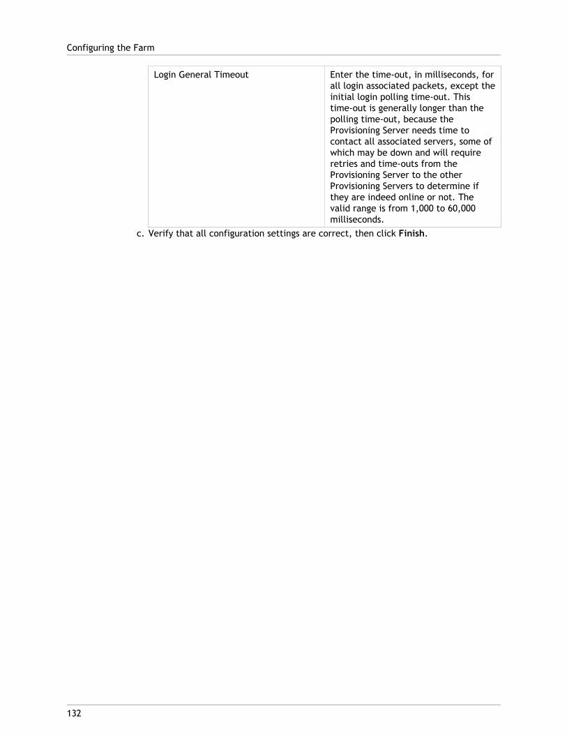
Login General Timeout Enter the time-out, in milliseconds, forall login associated packets, except theinitial login polling time-out. Thistime-out is generally longer than thepolling time-out, because theProvisioning Server needs time tocontact all associated servers, some ofwhich may be down and will requireretries and time-outs from theProvisioning Server to the otherProvisioning Servers to determine ifthey are indeed online or not. Thevalid range is from 1,000 to 60,000milliseconds.
c. Verify that all configuration settings are correct, then click Finish.
Configuring the Farm
132
133
Running the Configuration Wizard Silently
Run the Configuration Wizard silently to configure multiple Provisioning Servers that shareseveral of the same configuration settings such as the farm, site, and store locations.
PrerequisiteThe Configuration Wizard must first be run on any Provisioning Server in the farm that hasthe configuration settings that will be used in order to create the Provisioning Servicesdatabase and to configure the farm.
The basic steps involved in the silent configuration of servers within the farm include:
● Create a ConfigWizard.ans file from a configured Provisioning Server in the farm.
● Copy the ConfigWizard.ans file onto the other servers within the farm, and modify theIP address in the ConfigWizard.ans file to match each server in the farm.
● Run the ConfigWizard.exe with the /a parameter.
To Create the ConfigWizard.ans File1. Run the ConfigWizard.exe with the /s parameter on a configured server.
2. When selecting farm settings on the Farm Configuration page, choose the Join existingfarm option.
3. Continue selecting configuration settings on the remaining wizard pages, then clickFinish.
4. Copy the resulting ConfigWizard.ans file from the Provisioning Services Application Datadirectory. The location for this directory varies depending on the Windows version. ForWindows 2003, use \Documents and Settings\All Users\ApplicationData\Citrix\Provisioning Services. For Windows 2008 and Windows 2008 R2, use\ProgramData\Citrix\Provisioning Services.
To Copy and Modify the ConfigWizard.ans File1. For each server that needs to be configured, copy the ConfigWizard.ans file to the
Provisioning Services Application Data directory.

2. Edit the StreamNetworkAdapterIP= so that is matches the IP of the server beingconfigured. If there is more than one IP being used for Provisioning Services on theserver, add a comma between each IP address.
To Run the ConfigWizard.exe SilentlyTo configure servers, run the ConfigWizard.exe with /a parameter on each server thatneeds to be configured.
Note: To get the list of valid ConfigWizard parameters:
1. Run the ConfigWizard.exe with the /? parameter.
2. Open the resulting ConfigWizard.out file from the ConfigWizard.ans file from theProvisioning Services Application Data directory.
3. Scroll down to the bottom of the file to view all valid parameters.
Note: To get the list of valid ConfigWizard.ans commands with descriptions:
1. Run the ConfigWizard.exe with the /c parameter.
2. Open the resulting ConfigWizard.out file from the ConfigWizard.ans file from theProvisioning Services Application Data directory.
3. Scroll down to the bottom of the file to view all valid parameters.
Running the Configuration Wizard Silently
134
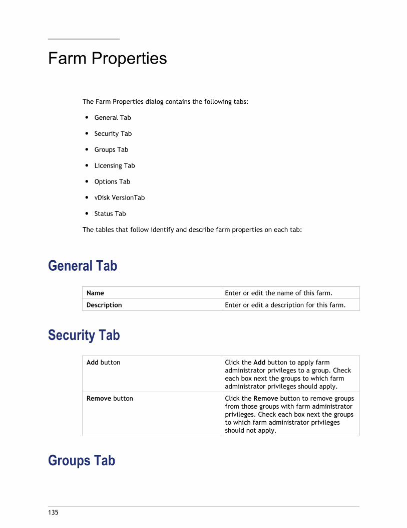
135
Farm Properties
The Farm Properties dialog contains the following tabs:
● General Tab
● Security Tab
● Groups Tab
● Licensing Tab
● Options Tab
● vDisk VersionTab
● Status Tab
The tables that follow identify and describe farm properties on each tab:
General TabName Enter or edit the name of this farm.
Description Enter or edit a description for this farm.
Security TabAdd button Click the Add button to apply farm
administrator privileges to a group. Checkeach box next the groups to which farmadministrator privileges should apply.
Remove button Click the Remove button to remove groupsfrom those groups with farm administratorprivileges. Check each box next the groupsto which farm administrator privilegesshould not apply.
Groups Tab
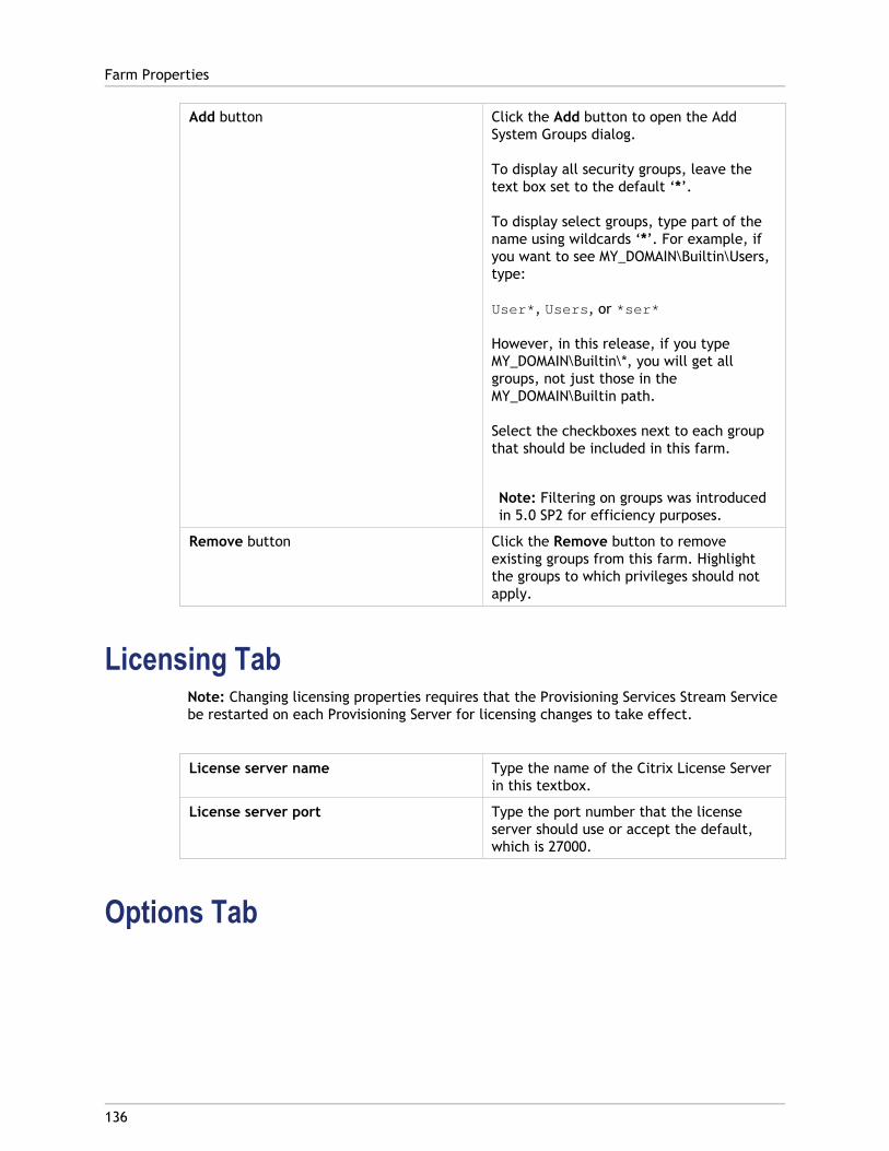
Add button Click the Add button to open the AddSystem Groups dialog.
To display all security groups, leave thetext box set to the default ‘*’.
To display select groups, type part of thename using wildcards ‘*’. For example, ifyou want to see MY_DOMAIN\Builtin\Users,type:
User*, Users, or *ser*
However, in this release, if you typeMY_DOMAIN\Builtin\*, you will get allgroups, not just those in theMY_DOMAIN\Builtin path.
Select the checkboxes next to each groupthat should be included in this farm.
Note: Filtering on groups was introducedin 5.0 SP2 for efficiency purposes.
Remove button Click the Remove button to removeexisting groups from this farm. Highlightthe groups to which privileges should notapply.
Licensing TabNote: Changing licensing properties requires that the Provisioning Services Stream Servicebe restarted on each Provisioning Server for licensing changes to take effect.
License server name Type the name of the Citrix License Serverin this textbox.
License server port Type the port number that the licenseserver should use or accept the default,which is 27000.
Options Tab
Farm Properties
136
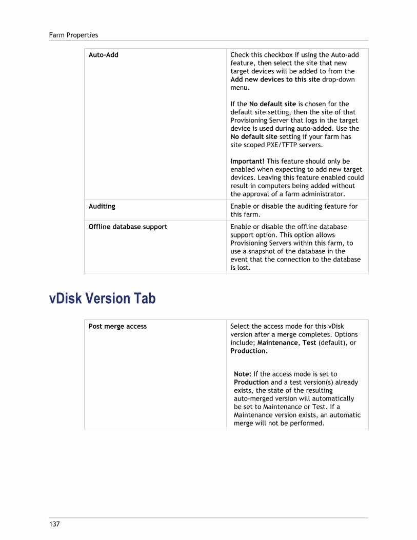
Auto-Add Check this checkbox if using the Auto-addfeature, then select the site that newtarget devices will be added to from theAdd new devices to this site drop-downmenu.
If the No default site is chosen for thedefault site setting, then the site of thatProvisioning Server that logs in the targetdevice is used during auto-added. Use theNo default site setting if your farm hassite scoped PXE/TFTP servers.
Important! This feature should only beenabled when expecting to add new targetdevices. Leaving this feature enabled couldresult in computers being added withoutthe approval of a farm administrator.
Auditing Enable or disable the auditing feature forthis farm.
Offline database support Enable or disable the offline databasesupport option. This option allowsProvisioning Servers within this farm, touse a snapshot of the database in theevent that the connection to the databaseis lost.
vDisk Version TabPost merge access Select the access mode for this vDisk
version after a merge completes. Optionsinclude; Maintenance, Test (default), orProduction.
Note: If the access mode is set toProduction and a test version(s) alreadyexists, the state of the resultingauto-merged version will automaticallybe set to Maintenance or Test. If aMaintenance version exists, an automaticmerge will not be performed.
Farm Properties
137
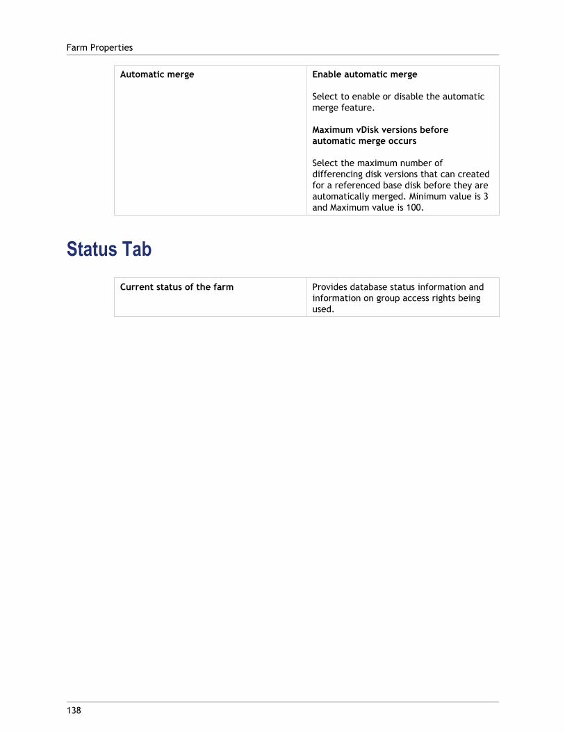
Automatic merge Enable automatic merge
Select to enable or disable the automaticmerge feature.
Maximum vDisk versions beforeautomatic merge occurs
Select the maximum number ofdifferencing disk versions that can createdfor a referenced base disk before they areautomatically merged. Minimum value is 3and Maximum value is 100.
Status TabCurrent status of the farm Provides database status information and
information on group access rights beingused.
Farm Properties
138
139
Farm Tasks
The farm is initially configured when you run the Configuration Wizard. The wizard promptsyou for the farm’s name, a store, and a device collection. When you first open the Console,those objects display in the tree.
The wizard also prompts you for additional farm information such as the name of thelicense server, your user account information, and those servers that can serve thebootstrap file to target devices. You can always rerun the wizard to change settings. Youcan also choose to make farm configuration changes using the Farm Properties Dialog.
A farm administrator can view and manage all objects in any farm to which they haveprivileges. Only farm administrators can perform all tasks at the farm level, including:
● Managing Farm Connections
● Configuring Farm Properties
● Creating a New Site in a Farm
● Managing Site Properties
● Managing Stores
● Managing Views
140
Farm Connections
Connecting to a Farm1. Right-click on Provisioning Services Console in the Console tree, then select Connect to
farm...
2. Under Server Information, type the name or IP address of a Streaming Server on thefarm and the port configured for server access.
3. Select to log in using one of the following methods:
● Use the Windows credentials that you are currently logged with, then optionallyenable the Auto-login on application start or reconnect feature.
● Use different Windows credentials by entering the username, password, and domainassociated with those credentials, then optionally enable the Save password andAuto-login on application start or reconnect feature.
4. Click Connect. The Farm icon appears in the Console tree.
Managing ConnectionsYou can manage connections to farms from the Manage Connections dialog. To open thedialog, right-click on the Provisioning Services Console icon in the tree, then select theManage Connections... menu option.
141
Managing Sites
A site provides both a site administrator and farm administrator, with a method ofrepresenting and managing logical groupings of Provisioning Servers, Device Collections, andlocal shared storage.
A site administrator can perform any task that a device administrator or device operatorwithin the same farm can perform.
A site administrator can also perform the following tasks:
Farm-level tasks
● Managing Site Properties
● Managing Stores
Some Site-level tasks include:
● Defining Device administrator and device operator roles.
● Managing Provisioning Servers
● Managing connections
● Creating a New Site in a Farm
● Rebalancing Devices on the Provisioning Server
● Importing Target Devices into Collections
● Accessing Audit Information
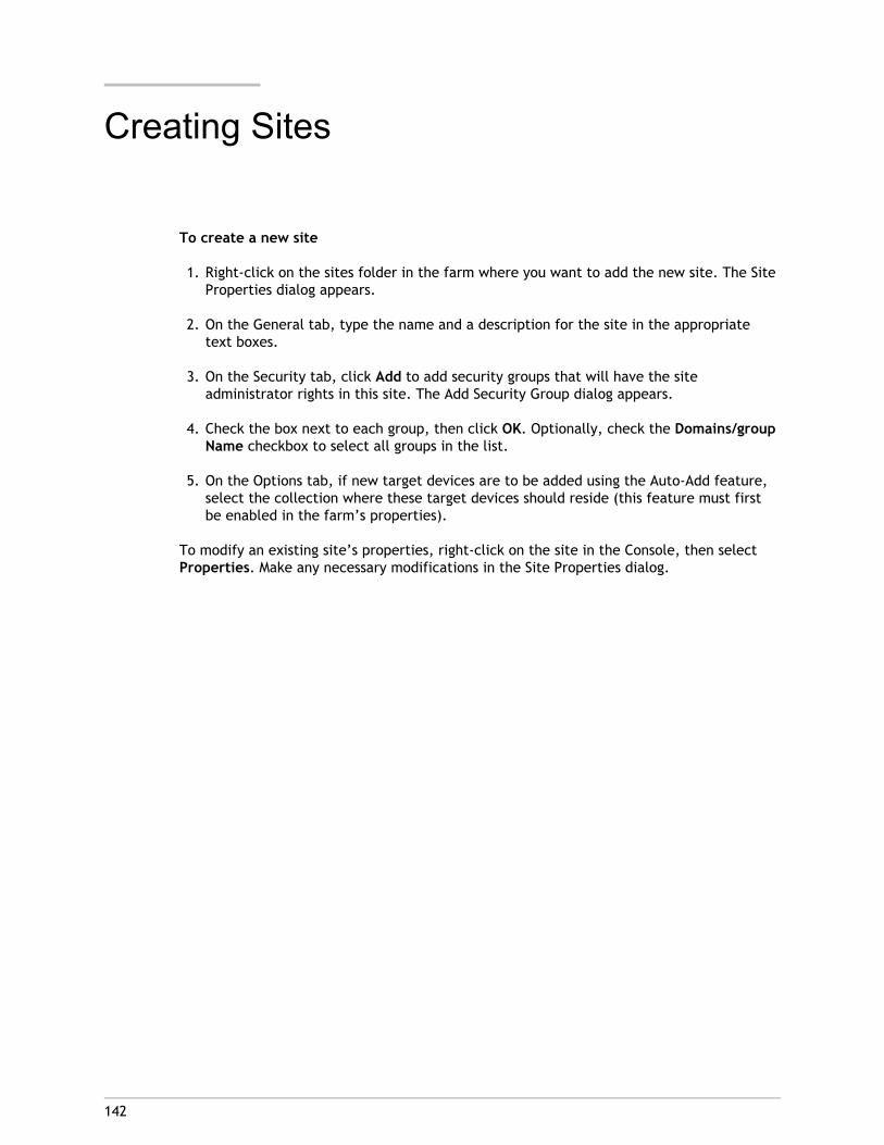
142
Creating Sites
To create a new site
1. Right-click on the sites folder in the farm where you want to add the new site. The SiteProperties dialog appears.
2. On the General tab, type the name and a description for the site in the appropriatetext boxes.
3. On the Security tab, click Add to add security groups that will have the siteadministrator rights in this site. The Add Security Group dialog appears.
4. Check the box next to each group, then click OK. Optionally, check the Domains/groupName checkbox to select all groups in the list.
5. On the Options tab, if new target devices are to be added using the Auto-Add feature,select the collection where these target devices should reside (this feature must firstbe enabled in the farm’s properties).
To modify an existing site’s properties, right-click on the site in the Console, then selectProperties. Make any necessary modifications in the Site Properties dialog.
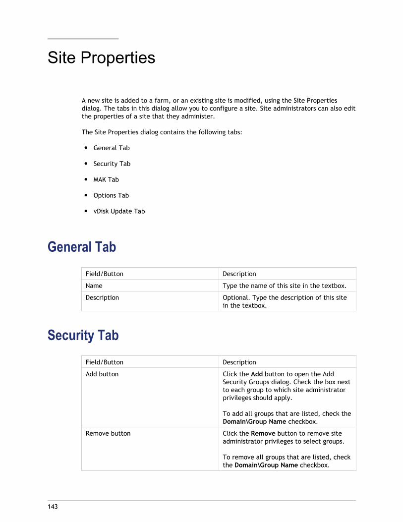
143
Site Properties
A new site is added to a farm, or an existing site is modified, using the Site Propertiesdialog. The tabs in this dialog allow you to configure a site. Site administrators can also editthe properties of a site that they administer.
The Site Properties dialog contains the following tabs:
● General Tab
● Security Tab
● MAK Tab
● Options Tab
● vDisk Update Tab
General TabField/Button Description
Name Type the name of this site in the textbox.
Description Optional. Type the description of this sitein the textbox.
Security TabField/Button Description
Add button Click the Add button to open the AddSecurity Groups dialog. Check the box nextto each group to which site administratorprivileges should apply.
To add all groups that are listed, check theDomain\Group Name checkbox.
Remove button Click the Remove button to remove siteadministrator privileges to select groups.
To remove all groups that are listed, checkthe Domain\Group Name checkbox.
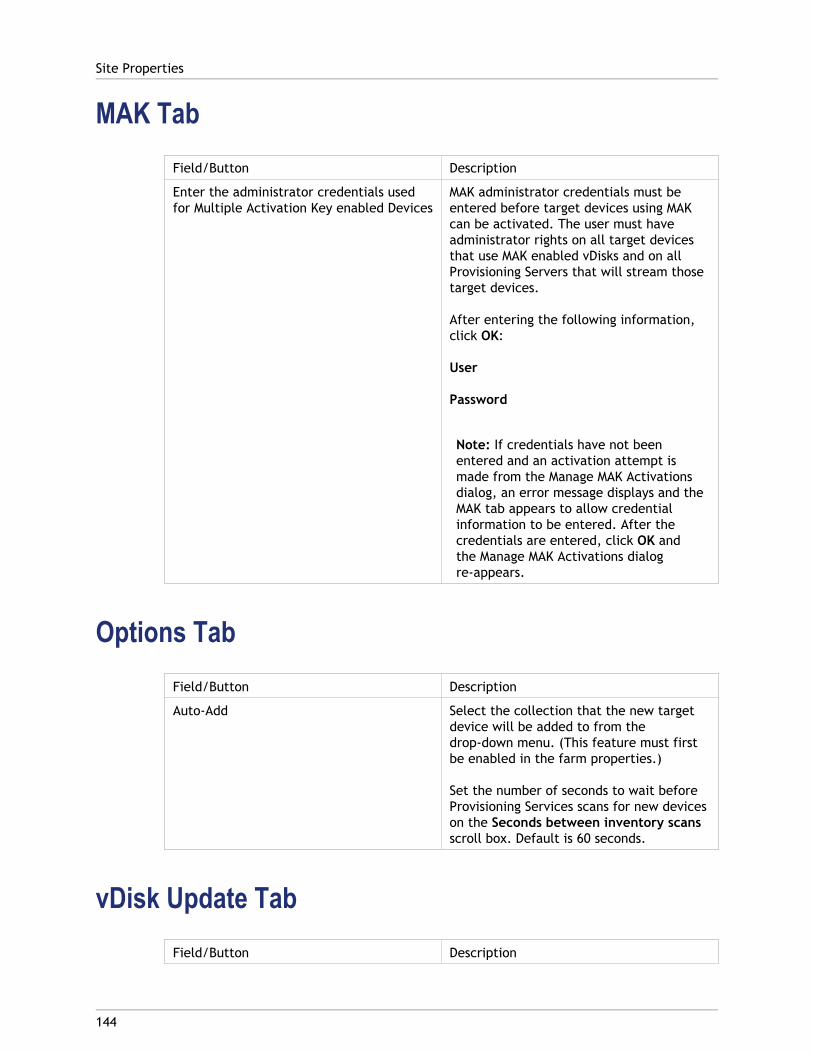
MAK TabField/Button Description
Enter the administrator credentials usedfor Multiple Activation Key enabled Devices
MAK administrator credentials must beentered before target devices using MAKcan be activated. The user must haveadministrator rights on all target devicesthat use MAK enabled vDisks and on allProvisioning Servers that will stream thosetarget devices.
After entering the following information,click OK:
User
Password
Note: If credentials have not beenentered and an activation attempt ismade from the Manage MAK Activationsdialog, an error message displays and theMAK tab appears to allow credentialinformation to be entered. After thecredentials are entered, click OK andthe Manage MAK Activations dialogre-appears.
Options TabField/Button Description
Auto-Add Select the collection that the new targetdevice will be added to from thedrop-down menu. (This feature must firstbe enabled in the farm properties.)
Set the number of seconds to wait beforeProvisioning Services scans for new deviceson the Seconds between inventory scansscroll box. Default is 60 seconds.
vDisk Update TabField/Button Description
Site Properties
144

Enable automatic vDisk updates on this site Select this checkbox to enable automaticvDisks to occur, then select the server thatshould run the updates for this site.
Site Properties
145

146
Managing Administrative Roles
The ability to view and manage objects within a Provisioning Server implementation isdetermined by the administrative role assigned to a group of users. Provisioning Servicesmakes use of groups that already exist within the network (Windows or Active DirectoryGroups). All members within a group will share the same administrative privileges within afarm. An administrator may have multiple roles if they belong to more than one group.
The following administrative roles can be assigned to a group:
● Farm Administrator
● Site Administrator
● Device Administrator
● Device Operator
After a group is assigned an administrator role through the Console, if a member of thatgroup attempts to connect to a different farm, a dialog displays requesting that aProvisioning Server within that farm be identified (the name and port number). You are alsorequired to either use the Windows credentials you are currently logged in with (defaultsetting), or enter your Active Directory credentials. Provisioning Services does not supportusing both domain and workgroups simultaneously.
When the information is sent to and received by the appropriate server farm, the role thatwas associated with the group that you are a member of, determines your administrativeprivileges within this farm. Group role assignments can vary from farm to farm.
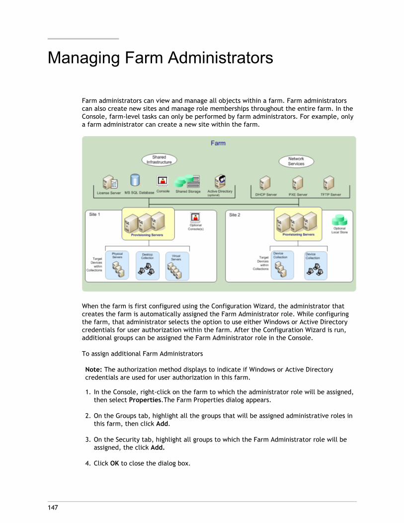
147
Managing Farm Administrators
Farm administrators can view and manage all objects within a farm. Farm administratorscan also create new sites and manage role memberships throughout the entire farm. In theConsole, farm-level tasks can only be performed by farm administrators. For example, onlya farm administrator can create a new site within the farm.
When the farm is first configured using the Configuration Wizard, the administrator thatcreates the farm is automatically assigned the Farm Administrator role. While configuringthe farm, that administrator selects the option to use either Windows or Active Directorycredentials for user authorization within the farm. After the Configuration Wizard is run,additional groups can be assigned the Farm Administrator role in the Console.
To assign additional Farm Administrators
Note: The authorization method displays to indicate if Windows or Active Directorycredentials are used for user authorization in this farm.
1. In the Console, right-click on the farm to which the administrator role will be assigned,then select Properties.The Farm Properties dialog appears.
2. On the Groups tab, highlight all the groups that will be assigned administrative roles inthis farm, then click Add.
3. On the Security tab, highlight all groups to which the Farm Administrator role will beassigned, the click Add.
4. Click OK to close the dialog box.
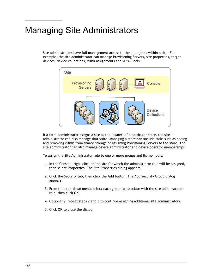
148
Managing Site Administrators
Site administrators have full management access to the all objects within a site. Forexample, the site administrator can manage Provisioning Servers, site properties, targetdevices, device collections, vDisk assignments and vDisk Pools.
If a farm administrator assigns a site as the ‘owner’ of a particular store, the siteadministrator can also manage that store. Managing a store can include tasks such as addingand removing vDisks from shared storage or assigning Provisioning Servers to the store. Thesite administrator can also manage device administrator and device operator memberships
To assign the Site Administrator role to one or more groups and its members:
1. In the Console, right-click on the site for which the administrator role will be assigned,then select Properties. The Site Properties dialog appears.
2. Click the Security tab, then click the Add button. The Add Security Group dialogappears.
3. From the drop-down menu, select each group to associate with the site administratorrole, then click OK.
4. Optionally, repeat steps 2 and 3 to continue assigning additional site administrators.
5. Click OK to close the dialog.
149
Managing Device Administrators
Device administrators manage device collections to which they have privileges.Management tasks include assigning and removing vDisks from a device, editing deviceproperties and viewing vDisk Properties (read-only). Device collections consist of a logicalgrouping of devices. For example, a device collection could represent a physical location, asubnet range, or a logical grouping of target devices. A target device can only be a memberof one device collection.
To assign the Device Administrator role to one or more groups and its members:
1. In the Console tree, expand the site where the device collection exists, then expandthe Device Collections folder.
2. Right-click on the device collection that you want to add device administrators to, thenselect Properties. The Device Collection Properties dialog appears.
3. On the Security tab, under the Groups with ‘Device Administrator’ access list, clickAdd. The Add Security Group dialog appears.
4. To assign a group with the device administrator role, select each system group thatshould have device administrator privileges, then click OK.
5. Click OK to close the dialog box.

150
Managing Device Operators
A device operator has administrator privileges to perform the following tasks within aDevice Collection for which they have privileges:
● Boot and reboot a target device
● Shut down a target device
● View target device properties
To assign the Device Operator role to one or more groups:
1. In the Console tree, expand the site where the device collection exists, then expandthe Device Collections folder.
2. Right-click on the device collection that you want to add device operators to, thenselect Properties. The Device Collection Properties dialog appears.
3. On the Security tab, under the Groups with ‘Device Operator’ access list, click Add.The Add Security Group dialog appears.
4. To assign a group the Device Operator role, select each system group that should havedevice operator privileges, then click OK.
5. Click OK to close the dialog box.
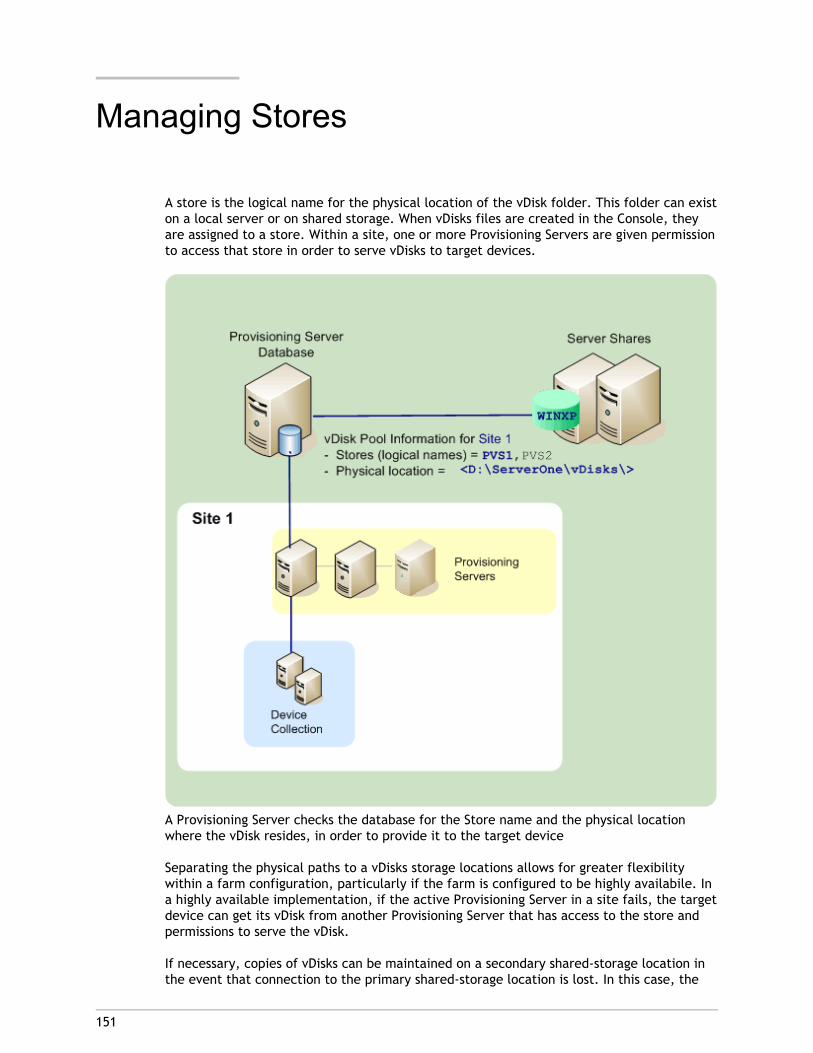
151
Managing Stores
A store is the logical name for the physical location of the vDisk folder. This folder can existon a local server or on shared storage. When vDisks files are created in the Console, theyare assigned to a store. Within a site, one or more Provisioning Servers are given permissionto access that store in order to serve vDisks to target devices.
A Provisioning Server checks the database for the Store name and the physical locationwhere the vDisk resides, in order to provide it to the target device
Separating the physical paths to a vDisks storage locations allows for greater flexibilitywithin a farm configuration, particularly if the farm is configured to be highly availabile. Ina highly available implementation, if the active Provisioning Server in a site fails, the targetdevice can get its vDisk from another Provisioning Server that has access to the store andpermissions to serve the vDisk.
If necessary, copies of vDisks can be maintained on a secondary shared-storage location inthe event that connection to the primary shared-storage location is lost. In this case, the
default path can be set in the store properties if all Provisioning Servers can use the samepath to access the store. If a particular server cannot use the path (the default path is notvalid for that server, not because of a connection loss, but because it is simply not valid)then an override path can be set in the store properties for that particular server.Provisioning Servers will always use either the default path (if the override path does notexist in the database) or the override path if it does exists in the database.
For more information on stores, refer to any of the following topics:
● Store administrative privileges
● Store properties
● Store configuration and management tasks
Managing Stores
152
153
Store Administrative Privileges
Stores are defined and managed at the farm level by a farm administrator. Access orvisibility to a store depends on the users administrative privileges:
● Farm Administrators have full access to all stores within the farm
● Site Administrators have access to only those stores owned by the site
● Device Administrators and Device Operators have read-only access. Site Administratorsmay also have read-only access if that store exists at the farm level, or if that storebelongs to another site.
For details, refer to Managing Administrative Roles
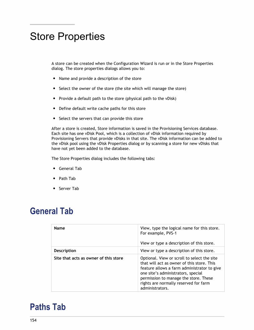
154
Store Properties
A store can be created when the Configuration Wizard is run or in the Store Propertiesdialog. The store properties dialogs allows you to:
● Name and provide a description of the store
● Select the owner of the store (the site which will manage the store)
● Provide a default path to the store (physical path to the vDisk)
● Define default write cache paths for this store
● Select the servers that can provide this store
After a store is created, Store information is saved in the Provisioning Services database.Each site has one vDisk Pool, which is a collection of vDisk information required byProvisioning Servers that provide vDisks in that site. The vDisk information can be added tothe vDisk pool using the vDisk Properties dialog or by scanning a store for new vDisks thathave not yet been added to the database.
The Store Properties dialog includes the following tabs:
● General Tab
● Path Tab
● Server Tab
General TabName View, type the logical name for this store.
For example, PVS-1
View or type a description of this store.
Description View or type a description of this store.
Site that acts as owner of this store Optional. View or scroll to select the sitethat will act as owner of this store. Thisfeature allows a farm administrator to giveone site’s administrators, specialpermission to manage the store. Theserights are normally reserved for farmadministrators.
Paths Tab
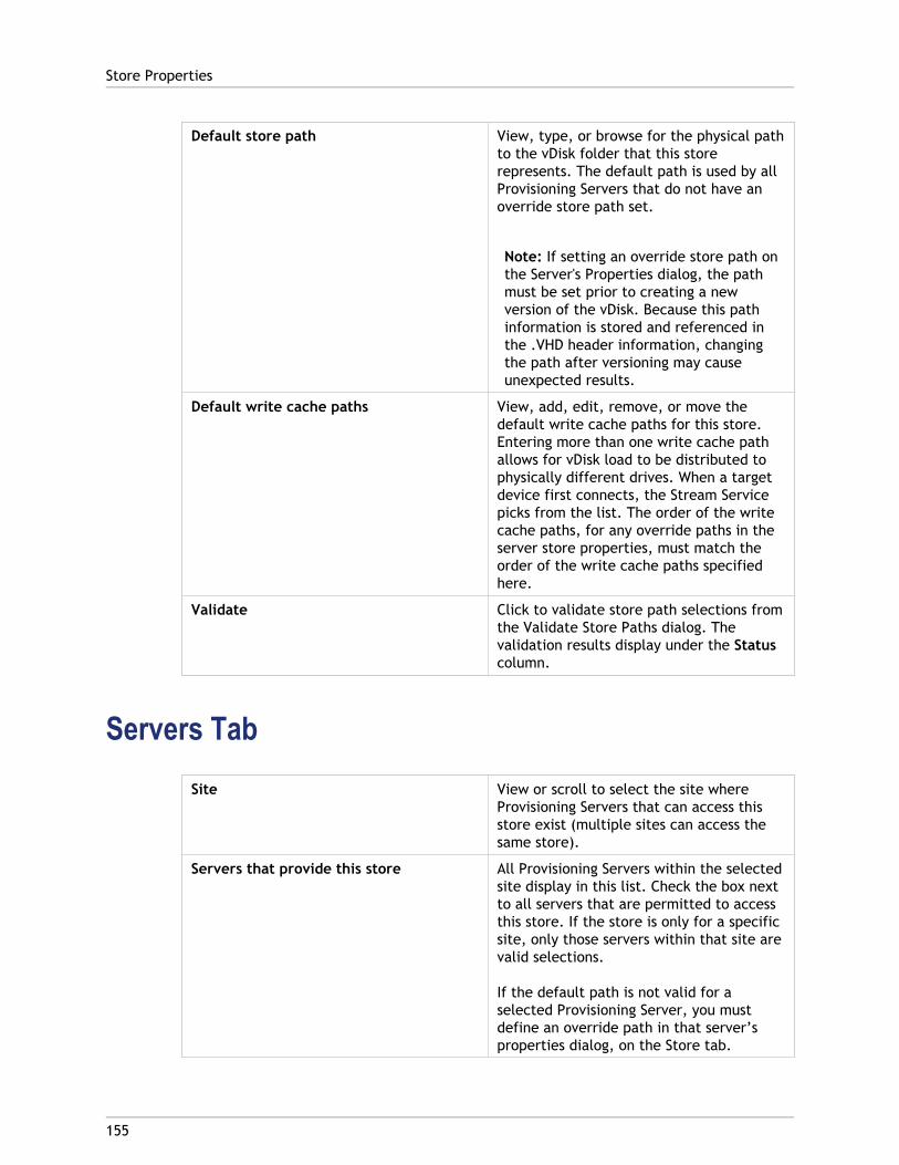
Default store path View, type, or browse for the physical pathto the vDisk folder that this storerepresents. The default path is used by allProvisioning Servers that do not have anoverride store path set.
Note: If setting an override store path onthe Server's Properties dialog, the pathmust be set prior to creating a newversion of the vDisk. Because this pathinformation is stored and referenced inthe .VHD header information, changingthe path after versioning may causeunexpected results.
Default write cache paths View, add, edit, remove, or move thedefault write cache paths for this store.Entering more than one write cache pathallows for vDisk load to be distributed tophysically different drives. When a targetdevice first connects, the Stream Servicepicks from the list. The order of the writecache paths, for any override paths in theserver store properties, must match theorder of the write cache paths specifiedhere.
Validate Click to validate store path selections fromthe Validate Store Paths dialog. Thevalidation results display under the Statuscolumn.
Servers TabSite View or scroll to select the site where
Provisioning Servers that can access thisstore exist (multiple sites can access thesame store).
Servers that provide this store All Provisioning Servers within the selectedsite display in this list. Check the box nextto all servers that are permitted to accessthis store. If the store is only for a specificsite, only those servers within that site arevalid selections.
If the default path is not valid for aselected Provisioning Server, you mustdefine an override path in that server’sproperties dialog, on the Store tab.
Store Properties
155

Validate Click to validate store path selections fromthe Validate Store Paths dialog. Thevalidation results display under the Statuscolumn.
Store Properties
156
157
Store Configuration and ManagementTasks
The following lists tasks that are specific to configuring and managing a store:
● Creating a Store
● Accessing Audit Information
Creating a Store
1. In the Console tree, right-click on Stores, then select the Create store menu option.The Store Properties dialog appears.
2. On the General tab, type the store name (logical name for this storage location) and adescription of this store.
3. Optional. Select the site that will act as owner of this store. Otherwise, accept thedefault <None> so that only farm administrators can manage this store.
4. On the Servers tab, select a site from the list. All Provisioning Servers in that siteappear.
5. Check the box each to each server that is permitted to access this store. If the store isonly for a specific site, only those servers within that site are valid selections. Also, ifthe default path is not valid for a selected server, an override path must be defined infor that server on the Server Properties dialogs Store tab. Repeat this step for each siteif necessary. (If this procedure is performed by a site administrator, only those sitesthat they administer appear.)
6. On the Paths dialog, type or browse for the default path for this store (physical locationof the vDisk folder). Optionally, a new folder can be created by clicking on the browsebutton, and then cIicking on Create New Folder. If the user is a site administrator, onlythose sites that they administer will be available in the list.
7. The write cache path(s) for the selected store display under the paths list. Optionally, anew store cache folder can be created by clicking on the browse button, and thencIicking on Create New Folder. Additional write cache paths can be added for use bythe store by clicking Add. Entering more than one write cache paths allows for vDiskload to be distributed to physically different drives. When a target device firstconnects, the Stream Service picks from the list. If using HA, the order of thewrite-cache paths for any override paths in store properties for that server, must matchthe order of the write-cache paths specified here If a write cache path is not selectedand the OK button is clicked, the user is prompted to create the default write cachepath. Click OK on this message to create the default write cache path(C:\pvsstore\WriteCache).
8. After configuring the store and paths this store will use, click Validate to open theValidate Store Paths dialog and validate the path settings.

9. Under the Status column, view the path validation results. Click Close to close thisdialog and return to the Store Properties dialog to make any necessary changes or tocontinue.
10. Click OK to save Property settings.
Store Configuration and Management Tasks
158
159
Managing Provisioning Servers
A Provisioning Server is any server that has Stream Services installed. Provisioning Serversare used to stream software from vDisks, as needed, to target devices. In someimplementations, vDisks reside directly on the Provisioning Server. In largerimplementations, Provisioning Servers get the vDisk from a shared-storage device on thenetwork.
Provisioning Servers also retrieve and provide configuration information to and from theProvisioning Services database. Provisioning Server configuration options are available toensure high availability and load-balancing of target device connections
To configure a Provisioning Server and software components for the first time, run theConfiguration Wizard (the Configuration Wizard can be re-run on a Provisioning Server at alater date in order to change network configuration settings). Refer to the Installation andConfiguration Guide for Configuration Wizard details.
After the Provisioning Server software components are successfully installed, and thewizard configurations have been made, servers are managed through the ProvisioningServices Console.
160
Provisioning Servers in the Console
A Provisioning Server is any server that has Stream Services installed. Provisioning Serversare used to stream software from vDisks, as needed, to target devices. In someimplementations, vDisks reside directly on the Provisioning Server. In largerimplementations, Provisioning Servers get the vDisk from a shared-storage device on thenetwork.
Provisioning Servers also retrieve and provide configuration information to and from theProvisioning Services database. Provisioning Server configuration options are available toensure high availability and load-balancing of target device connections
To configure a Provisioning Server and software components for the first time, run theConfiguration Wizard (the Configuration Wizard can be re-run on a Provisioning Server at alater date in order to change network configuration settings). Refer to the Installation andConfiguration Guide for Configuration Wizard details.
After the Provisioning Server software components are successfully installed, and thewizard configurations have been made, servers are managed through the ProvisioningServices Console. The Console is used to perform Provisioning Server management taskssuch as editing the configuration settings or the properties of existing Provisioning Servers.
Provisioning Servers appear in the Console main window as members of a site within a farm.To manage Provisioning Servers that belong to a specific site, you must have theappropriate administrative role (Site Administrator for this site, or Farm Administrator).
Note: In the Console, the appearance of the Provisioning Server icon indicates thatserver’s current status.
In the Console, Provisioning Servers are managed by performing actions on them. Thefollowing actions can be performed. To view a list of actions that can be performed on aselected Provisioning Server, choose from the following options:
● Click the Action menu in the menu bar
● Right-click on a Provisioning Server in the Console
● Enable the Action pane from the Views menu
Note: Actions appear disabled if they do not apply to the selected Provisioning Server(refer to “Management Tasks” for task details).
161
Provisioning Server Properties
On the Console, the Provisioning Server Properties dialog allows you to modify ProvisioningServer configuration settings. To view an existing Provisioning Server’s properties, chooseone of the following methods:
● Highlight a Provisioning Server, then select Properties from the Action menu.
● Right-click a Provisioning Server, then select Properties
● If the details pane is open, highlight a Provisioning Server, then select the Propertiesmenu item from the list of actions.
The Server Properties dialog includes the following tabs:
● General
● Network
● Stores
● Options
● Logging
Note: Provisioning Services displays a message if a change made on a Provisioning ServerProperties dialog requires that the server be rebooted.
GeneralName and Description
Displays the name of the Provisioning Server and a brief description. The maximumlength for the server name is 15 characters. Do not enter FQDN for the server name.
Power Rating
A power rating is assigned to each server, which is then used when determining whichserver is least busy. The scale to use is defined by the administrator.
For example, an administrator may decide to rate all servers on a scale of 1 to 10, or ona scale of 100 to 1000. Using the scale of 1 to 10, a server with a rating of 2 is consideredtwice as powerful as a server with a rating of 1; therefore it would be assigned twice asmany target devices. Likewise, when using a scale of 100 to 1000, a server with a powerrating of 200 is considered twice as powerful as a server with the rating of 100; thereforeit would also be assigned twice as many target devices.
Using the default setting of 1.0 for all servers results in even device loading acrossservers. In this case, the load balancing algorithm does not account for individual server
power.
Ratings can range between 0.1-1000.0; 1.0 is the default.
Note: The load balancing method is defined in vDisk Load Balancing dialog.
Log events to the server's Window Event Log
Select this option if you want this Provisioning Server's events to be logged in theWindows Event log.
Advanced Server Properties
Server tab
Threads per port — Number of threads in the thread pool that service UDP packetsreceived on a given UDP port. Between four and eight are reasonable settings. Largernumbers of threads allow more target device requests to be processed simultaneously,but is consumes more system resources.
Buffers per thread — Number of packet buffers allocated for every thread in a threadpool. The number of buffers per thread should be large enough to enable a single threadto read one IO transaction from a target device. So buffers per threads should ideally beset to (IOBurstSize / MaximumTransmissionUnit) + 1). Setting the value too largeconsumes extra memory, but does not hurt efficiency. Setting the value too smallconsumes less RAM, but detrimentally affects efficiency.
Server cache timeout — Every server writes status information periodically to theProvisioning Services database. This status information is time-stamped on every write. Aserver is considered ‘Up’ by other servers in the farm, if the status information in thedatabase is newer than the Server cache timeout seconds. Every server in the farm willattempt to write its status information every (Server cache timeout/2) seconds, i.e. attwice the timeout rate. A shorter server cache timeout value allows servers to detectoffline servers more quickly, at the cost of extra database processing. A longer Servercache timeout period reduces database load at the cost of a longer period to detect lostservers.
Local and Remote Concurrent I/O limits — Controls the number of concurrent outstandingI/O transactions that can be sent to a given storage device. A storage device is definedas either a local drive letter (C: or D: for example) or as the base of a UNC path, forexample \\ServerName.
Since the PVS service is a highly multi-threaded service, it is possible for it to sendhundreds of simultaneous I/O requests to a given storage device. These are usuallyqueued up by the device and processed when time permits. Some storage devices,Windows Network Shares most notably, do not deal with this large number of concurrentrequests well. They can drop connections, or take unrealistically long to processtransactions in certain circumstances. By throttling the concurrent I/O transactions inthe PVS Service, better performance can be achieved with these types of devices.
Local device is defined as any device starting with a drive letter. Remote is defined asany device starting with a UNC server name. This a simple way to achieve separate limitsfor network shares and for local drives.
If you have a slow machine providing a network share, or slow drives on the machine,then a count of 1 to 3 for the remote limit may be necessary to achieve the best
Provisioning Server Properties
162
performance with the share. If you are going to fast local drives, you might be able to setthe local count fairly high. Only empirical testing would provide you with the optimumsetting for a given hardware environment. Setting either count to 0 disables the featureand allows the PVS Service to run without limits. This might be desirable on very fastlocal drives.
If a network share is overloaded, you’ll see a lot more device retries and reconnectionsduring boot storms. This is caused by read/write and open file times > 60 seconds.Throttling the concurrent I/O transactions on the share reduces these types of problemsconsiderably.
Network tab
Maximum transmission unit — Number of bytes that fit in a single UDP packet. Forstandard Ethernet, the default value is correct. If you are attempting to operate over aWAN, then a smaller value may be needed to prevent IP fragmentation. ProvisioningServices currently does not support IP fragmentation and reassembly. Also, if you areusing a device or software layer that adds bytes to every packet (for security reasons forexample), a smaller value may be needed. If your entire infrastructure supports jumbopackets (Provisioning Services NIC, target device NIC and any intervening switches and/orrouters) then you can set the MTU to 50 bytes less than your jumbo packet max size toachieve much higher network throughput.
I/O burst size — The number of bytes that will be transmitted in a single read/writetransaction before an ACK is sent from the server or device. The larger the IO burst, thefaster the throughput to an individual device, but the more stress placed on the serverand network infrastructure. Also, larger IO Bursts increase the likelihood of lost packetsand costly retries. Smaller IO bursts reduce single client network throughput, but alsoreduce server load. Smaller IO bursts also reduce the likelihood of retries. IO Burst Size /MTU size must be <= 32, i.e. only 32 packets can be in a single IO burst before a ACK isneeded.
Socket communications — Enable non-blocking I/O for network communications.
Pacing tab
Boot pause seconds — The amount of time that the device will be told to pause if theMaximum devices booting limit has been reached. The device will display a message tothe user and then wait Boot pause seconds before attempting to continue to boot. Thedevice will continue to check with the server every Boot pause seconds until the serverallows the device to boot.
Maximum boot time — The amount of time a device will be considered in the bootingstate. Once a device starts to boot, the device will be considered booting until theMaximum boot time has elapsed for that device. After this period, it will no longer beconsidered booting (as far as boot pacing is concerned) even if the device has notactually finished booting. Maximum boot time can be thought of as a time limit perdevice for the booting state for boot pacing.
Maximum devices booting — The maximum number of devices a server allows to boot atone time before pausing new booting devices. The number of booting devices must dropbelow this limit before the server will allow more devices to boot.
vDisk creation pacing — Amount of pacing delay to introduce when creating a vDisk onthis Provisioning Server. Larger values increase the vDisk creation time, but reduceProvisioning Server overhead to allow target devices that are running, to continue to run
Provisioning Server Properties
163
efficiently.
Device tab
License timeout — Amount of time since last hearing from a target device to hold alicense before releasing it for use by another target device. If a target device shuts downabnormally (loses power for example) its license is held for this long.
NetworkIP Address
The IP addresses that the Stream Service should use for a target device to communicatewith this Provisioning Server. When adding a new Provisioning Server, enter the valid IPaddress for the new server.
Add — Add an IP address for the selected Provisioning Server.
Edit — Opens the IP address dialog so that IP address for the selected Provisioning Servercan be changed.
Remove — Removes the selected IP address from the list of available IP addresses for theselected Provisioning Server.
Ports
Enter the First and Last UDP port numbers to indicate a range of ports to be used by theStream Service for target device communications.
Note: The minimum is five ports in a range. The default first port number is 6910 andthe last port number is 6930 .
StoresStores
Lists all stores (logical names representing physical paths to vDisks that are available tothis Provisioning Server.
Add — Opens the Store Properties dialog so that a new store and that store’s propertiescan be included in the list of stores, which overrides the default path.
Edit — Opens the Store Properties dialog so that the store’s properties can be changed.Select an existing store, then click Edit to change that store’s properties.
Remove — Removes the selected store from the list of available stores for thisProvisioning Server.
Store Properties (opens when Add or Edit is selected under Stores)
Provisioning Server Properties
164
Store — The name of the store. This displays populated when editing an existing store. Ifthis is a new store, select the store from the drop-down list.
Path used to access the store — The store path is only required if you need to overridethe ‘default path’ configured in the store properties. If the default path in the storeproperties is valid for this server, leave the path for the store blank in the server storeproperties.
Note: If setting an override store path on the Server's Properties dialog, the path mustbe set prior to creating a new version of the vDisk. Because this path information isstored and referenced in the .VHD header information, changing the path afterversioning may cause unexpected results.
Write cache paths — Click the Add or Edit buttons to open the Write cache path dialog,then enter the appropriate write cache path for this store.
Select an existing path from the list, then click Remove to remove the paths associationwith the store.
Use the Move Up and Move Down buttons to change the order of cache path priority. Ifconfigured for high availability, the order that the cache paths are listed must be thesame order for each server.
OptionsActive Directory
Automate computer account password updates— If target devices are domain members,and require renegotiation of machine passwords between Windows Active Directory andthe target devices, select the Automate computer account password updates, and usethe slider to set the number of days between renegotiation.
Enable automatic vDisk updates
Check to enable vDisks to be updated automatically, then set the time of day to checkfor updates.
LoggingLogging Level
Select from the following logging level options:
TRACE
TRACE logs all valid operations.
DEBUG
Provisioning Server Properties
165
The DEBUG level logs details related to a specific operation and is the highest level oflogging. If logging is set to DEBUG, all other levels of logging information are displayed inthe log file.
INFO
Default logging level. The INFO level logs information about workflow, which generallyexplains how operations occur.
WARN
The WARNING level logs information about an operation that completes successfully, butthere are issues with the operation.
ERROR
The ERROR level logs information about an operation that produces an error condition.
FATAL
The FATAL level logs information about an operation that the system could not recoverfrom.
File size maximum
Enter the maximum size that a log file can reach before a new file is created.
Backup files maximum
Enter the maximum number of backup log files to retain. When this number is reached,the oldest log file is automatically deleted.
Provisioning Server Properties
166
167
Provisioning Server Tasks
Use the following tasks to managing Provisioning Servers in your farm:
● Copying and Pasting Server Properties
● Marking a Server as Down
● Deleting a Server
● Starting, Stopping, or Restarting Provisioning Services on a Server
● Showing Server Connections
● Balancing Target Devices on a Server
● Checking for vDisk Access Updates
● Configuring Provisioning Servers Manually
● Auditing
● Configure Bootstrap
Note: After making any changes to a Provisioning Server’s properties, restart the StreamService to implement those changes. Use caution when restarting services. If targetdevices are connected to the Provisioning Server, changes could prevent the device fromreconnecting. The IP address field on the Network tab must reflect the real static IPaddress of the Provisioning Server.

168
Adding Additional Provisioning Servers
To add additional Provisioning Servers, install the Provisioning Services software on eachserver that is to a member of the farm. Run the Provisioning Services Installation Wizard,then the Configuration Wizard on each server.
Note: The maximum length for the server name is 15 characters. Do not enter FQDN forthe server name
When the Configuration Wizard prompts for the site to add the server to, choose an existingsite or create a new site.
After adding Provisioning Servers to the site, start the Console and connect to the farm.Verify that all sites and servers display appropriately in the Console window.
169
Copying and Pasting Provisioning ServerProperties
To copy the properties of one Provisioning Server to another Provisioning Server:
1. Right-click on the Provisioning Server to copy properties from, then select Copy serverproperties. The Copy Server Properties dialog appears.
2. Enable the checkbox next to each property to copy, or click the Select all button toenable all properties to be copied.
3. Click Copy. Right-click on the Provisioning Server that you want to copy properties to,then select Paste .
170
Deleting a Provisioning Server
Occasionally, it may be necessary to delete a Provisioning Server from the list of availableProvisioning Servers in a farm.
Note: Before you can delete a Provisioning Server, you must first mark the server as downor take the server off line, otherwise the Delete menu option will not appear. TheStream Service can not be deleted.
When you delete a Provisioning Server, you do not affect vDisk image files or the contentsof the server drives. However, you do lose all paths to the vDisk image files on that server.
After deleting a Provisioning Server, target devices are no longer assigned to any vDiskimage files on that server. The target device records remain stored in the Virtual LAN Drivedatabase, but the device cannot access any vDisk that was associated with the deletedProvisioning Server.
Note: If there are vDisks associated with the Provisioning Server being deleted, it isrecommended that backup copies are created and stored in the vDisk directory prior todeleting.
To delete a Provisioning Server:
1. In the Console, highlight the Provisioning Server that you want to delete, then selectShow connected devices from the Action menu, right-click menu, or Action pane. TheConnected Target Devices dialog appears.
2. In the Target Device table, highlight all devices in the list, then click Shutdown. TheTarget Device Control dialog appears.
3. Type a message to notify target devices that the Provisioning Server is being shut down.
4. Scroll to select the number of seconds to delay after the message is received.
5. If the Stream Service is running on the Provisioning Server, stop the Stream Service(Starting, Restarting or Stopping the Stream Service).
6. Unassign all target devices from the Provisioning Server.
7. Highlight the Provisioning Server you want to delete, then choose Delete from theAction menu, right-click menu, or Action pane. A delete confirmation message appears.
8. Click Yes to confirm the deletion. The Provisioning Server is deleted and no longerdisplays in the Console.
171
Starting, Stopping, or RestartingProvisioning Services
Note: If the Stream Service you are trying to start, stop, or restart, is not on the localmachine, then the logged-in user must have Windows security permissions and beassigned the appropriate Provisioning Server administrative role to start or stop serviceson the selected Provisioning Server.
To start, stop, or restart Provisioning Services on a Provisioning Server:
1. Highlight the Provisioning Server in the Console, than select the Stream Services menuoption from the Actions menu, right-click menu, or Actions pane. The ProvisioningServer Control dialog appears.
2. Select from the following menu options:
Option Description
Start Starts the Stream Service
Stop Places the Provisioning Server in off-linemode
Restart After modifying Provisioning Serversettings, such as adding or removing IPs,restart the Stream Service
3. Highlight the Provisioning Servers that you want to take action on, then click thataction's button.
4. Click Close to exit the dialog.
172
Showing Provisioning Server Connections
To view and manage all target device connections to the Provisioning Server:
1. Highlight a Provisioning Server in the Console, then select Show connected devicesfrom the Action menu, right-click menu, or Action pane. The Connected TargetDevices dialog appears.
2. Select one or more target devices in the table to perform any of the followingconnection tasks:
Option Description
Shutdown Shuts down target devices that arehighlighted in the dialog.
Reboot Reboots target devices that arehighlighted in the dialog.
Message Opens the Edit Message dialog to allowyou to type, and then send a message totarget device(s) highlighted in thedialog.
When selecting Shutdown or Reboot, a dialog opens providing the option to type amessage that displays on the effected devices. The Shutdown or Reboot options can bedelayed by entering a delay time setting.
If a message appears confirming that the target device was successfully shut down orrebooted, but the icon in the Console window does not change accordingly, select theRefresh button.
173
Balancing the Target Device Load onProvisioning Servers
To achieve optimum server and target device performance within a highly availablenetwork configuration, enable load balancing for each vDisk.
1. Right-click on the vDisk in the Console, then select the Load Balancing... menu option.The vDisk Load Balancing dialog appears.
2. After enabling load balancing for the vDisk, the following additional load balancingalgorithm customizations can be set:
● Subnet Affinity – When assigning the server and NIC combination to use to providethis vDisk to target devices, select from the following subnet settings:
● None – ignore subnets; uses least busy server.
● Best Effort – use the least busy server/NIC combination from within the samesubnet. If no server/NIC combination is available within the subnet, select theleast busy server from outside the subnet. If more than one server is availablewithin the selected subnet, perform load balancing between those servers. BestEffort is the default setting.
● Fixed – use the least busy server/NIC combination from within the same subnet.Perform load balancing between servers within that subnet. If no server/NICcombination exists in the same subnet, do not boot target devices assigned tothis vDisk.
● Rebalance Enabled using Trigger Percent – Enable to rebalance the number oftarget devices on each server in the event that the trigger percent is exceeded.When enabled, Provisioning Services checks the trigger percent on each serverapproximately every ten minutes. For example: If the trigger percent on this vDiskis set to 25%, rebalancing occurs within ten minutes if this server has 25% more loadin comparison to other servers that can provide this vDisk.
Note: The load balance algorithm takes into account the Server Power setting of eachserver when determining load.
Load balancing will not occur if:
● less than five target devices are using a particular server
● the average number of target devices using all qualifying servers is less than five
● the number of target devices that are booting on a given server is more than 20% of thetotal number of devices connected to the server (preventing load shift thrashing duringa 'boot storm')
Load balancing is also considered when target devices boot. Provisioning Servicesdetermines which qualified Provisioning Server, with the least amount of load, should
provide the vDisk. Whenever additional qualified servers are brought online, rebalancingwill occur automatically.
To implement load balancing in a HA network configuration
● Assign a power rating to each Provisioning Server on the Server Properties' General tab.
● For each vDisk, select the load balancing method and define any additional loadbalancing algorithm settings on the vDisk Load Balancing dialog.
Note: Target devices that are not using a vDisk that is in HA mode will not be diverted toa different server. If a vDisk is misconfigured to have HA enabled, but they are not usinga valid HA configuration (Provisioning Servers and Store , target devices that use thatvDisk can lock up.
To rebalance Provisioning Server connections manually
1. In the Console, highlight the Provisioning Servers to rebalance, right-click then selectthe Rebalance devices menu option. The Rebalance Devices dialog appears.
2. Click Rebalance. A rebalance results message displays under the Status column.
3. Click Close to exit the dialog.
Balancing the Target Device Load on Provisioning Servers
174
175
Checking for Provisioning Server vDiskAccess Updates
To check for updates to vDisks that the selected Provisioning Server has access to:
1. Right-click the Provisioning Server in the details pane, then select Check for updates.
2. Select the Automatic... menu option.
3. Click OK on the confirmation message that appears. The vDisk is automatically updatedor is scheduled to be updated.
176
Configuring Provisioning ServersManually
If you are setting up a remote Provisioning Server, or have special requirements, you willneed to configure and start your Stream Services manually. The Configuration Wizard needsto be run on remote Provisioning Servers to insure that all settings are configured properly.Failure to run the Configuration Wizard may make it impossible for you to map a vDisk.Refer to the Installation and Configuration Guide if you are running the ConfigurationWizard for the first time.
Re-Running the Configuration WizardThe Configuration Wizard can be used when updating the Stream Service if the IP address ofyour Provisioning Server changes. If you change your Provisioning Server’s IP address for anyreason, simply re-run the Configuration Wizard and choose the new IP address whenprompted to do so. Completing the Configuration Wizard resets the appropriate IPaddresses in the configuration and restarts the Stream Service.
Starting and Configuring the Stream Service ManuallyAfter configuring the Stream Service, you must start the service for the change to takeeffect. It is highly recommended to set the service to start automatically each time aProvisioning Server boots.
Note: The Configuration Wizard starts and configures the necessary services to startautomatically. If you need to start and configure the services manually, see theinstructions below.
The Stream Service needs to be started in order for the Provisioning Server to operate.Start the following boot services if they have not yet been started:
● BOOTP Service or PXE Service
● TFTP Service
To manually start services:
1. From the Windows Start menu, select Settings, and then click Control Panel.
2. From the Control Panel, double-click the Administrative Tools icon.
3. From the Administrative Tools window double-click on the Services icon. The Serviceswindow appears.
4. From the Services window, right click on the service you want to start, then selectStart.
To manually configure services to start automatically upon booting the Provisioning Server:
1. From the Windows Start menu, select Settings, then click Control Panel.
2. From the Control Panel, double-click the Administrative Tools icon.
3. From the Administrative Tools window double-click on the Services icon. The Serviceswindow appears.
4. Right-click the service you want to configure, then select Properties.
5. Change the Startup Type to Automatic to configure the service to start automaticallyeach time the system boots.
Configuring Provisioning Servers Manually
177
178
Disabling Write Cache to ImprovePerformance When Using Storage DeviceDrives
Disable write caching to improve the performance when writing from a Provisioning Serverto storage device drives such as an IDE or SATA drive.
In Windows, to disable write caching on the server hard drive for the storage device onwhich your vDisks are stored:
1. On the Provisioning Server, open the Control Panel. Select AdministrativeTools>Computer Management.
2. Double-click the Disk Management node in the tree.
3. Right-click the storage device for which Windows write caching will be disabled.
4. Select Properties, then click the Hardware tab.
5. Click the Properties button.
6. Click the Policies tab.
7. Clear the Enable write caching on the disk checkbox.
8. Click OK, then click OK again.
9. Close the Computer Management window, then the Administrative Tools window.
10. Right-click the Provisioning Server node in the Console, then click Restart service.Alternatively, you can also re-run the Configuration Wizard to re-start the services, ormanually restart the services through the Windows Control Panel>AdministrativeTools>Services window. (At the Services window, right-click on the Stream Service, thenselect Start from the shortcut menu.)
179
Providing Provisioning Servers Access toStores
For each store, select the Provisioning Servers that can access that store:
1. In the Console, right-click on the Store, then select the Properties menu option. TheStore Properties dialog appears.
2. On the Servers tab, select the site where Provisioning Servers that should be able toaccess this store exists.
3. Enable the checkbox next to each Provisioning Server that can provide vDisks in thisstore, then click OK.
180
Managing Target Devices
A device, such as desktop computer or server, that boots and gets software from a vDisk onthe network, is considered a target device. A device that is used to create the vDisk imageis a considered a Master Target device.
The lifecycle of a target device includes:
● Preparing
● a Master target device used for creating a vDisk image
● a target device that will boot from a vDisk image● Adding target devices to a collection in the farm
● from the Console
● using Auto-Add
● importing● Assigning the target device type
● Maintaining target devices in the farm
After a target device is created, the device must be configured to boot from the network,the device itself must be configured to allow it to boot from the network, a vDisk must beassigned to the device, and a bootstrap file must be configured to provide the informationnecessary for that device to boot from the assigned vDisk. For details, refer to Bootingtarget devices from the network.
There are several types of target devices within a farm. For example, while a device isbeing used to create a vDisk image, it is considered a Master target device. All otherdevices are configured as a particular device type. The device Type determines a devicescurrent purpose, and determines if that device can access a particular vDisk version that isin Production, Test, or Maintenance.
The device Type is selected on the General tab of the Target Device Properties dialog,which includes the following options:
● Production: select this option to allow this target device to stream an assigned vDiskthat is currently in production (default).
● Maintenance: select this option to use this target device as a Maintenance device. Onlya Maintenance device can access and make changes to a vDisk version that isMaintenance mode (only the first Maintenance device to boot the version while inMaintenance mode, is allowed to access that version).
● Test: select this option to use this target device to access and test differencing diskversions that are currently in Test mode.
A target device becomes a member of a device collection when it is added to the farm. Theuse of device collections simplifies the management of all target devices within thatcollection. A target device can only be a member in one device collection. However, atarget device can exist in any number of views. If a target device is removed from thedevice collection, it is automatically removed from any associated views.
When target devices are added to a collection, that devices properties are stored in theProvisioning Services database. Target Device properties include information such as thedevice name and description, boot method, and vDisk assignments (refer to Target Deviceproperties for details).
Target Devices are managed and monitored using the Console and Virtual Disk Status Trayutilities.
In the Console, actions can be performed on:
● An individual target device
● All target devices within a collection
● All target devices within a view
To view target device related tasks, refer to Target Device Tasks
Managing Target Devices
181

182
Getting the Bootstrap File
A target device initiates the boot process by first loading a bootstrap program. A bootstrapprogram is a small program that runs before the operating system is loaded. ProvisioiningServices uses a special bootstrap program which initializes the streaming session betweenthe target device and the Provisioning Server. After this session starts, the operating systembegins to be streamed and loaded from the vDisk that was initiated.
There are three ways that a target device may load the bootstrap program.
● Over the network, via Preboot eXecution Environment (PXE)
● From a boot device stored on attached media
● From a BIOS Embedded bootstrap (OEM versions only)
After the target device's BIOS is configured to allow it to boot from the network, the devicecan boot and get a vDisk assignment from the Provisioning Server. The target devicefirmware gets the bootstrap file using standard network protocols.
Note: The device firmware (NIC) must support PXE 0.99j, PXE 2.1or greater.
Network Booting a Target DeviceThe DHCP service delivers IP configurations to a target device. It can also deliver thebootstrap file location using options 67, and 60 or 66. Consider delivering the bootstrap filelocation with a DHCP service to reduce the number of services and increase reliability.
Note: The BOOTP service can deliver IP configuration to a target device according toBOOTP tab. It can also deliver the boot program location using optional fields. Use of thisservice is no longer typical. Use this service only if DHCP does not meet yourrequirements.
The PXE service can deliver the bootstrap file location to a target device according to thePXE Specification Version 2.1. Use this service if a DHCP service exists and cannot bechanged, and another PXE service is not used.
The TFTP service delivers the bootstrap file to a target device on request. Use it if anotherTFTP service is not available.
The illustrations and steps that follow, describe the boot process both with and without theuse of PXE.
Using DHCP to Retrieve IP Address and Scope Options (Without PXE)
1. When a target device boots from the network, DHCP sends a request to the ProvisioningServer for an IP address and Scope Option settings (66 and 67). The Provisioning Serverreturns the information as requested.

2. Using TFTP, a request for the bootstrap file is sent from the target device to theProvisioning Server. The Provisioning Server downloads the boot file on the targetdevice.
3. The target device boots the assigned vDisk image.
Using DHCP with PXE to Retrieve IP Address and Scope Options
1. When a target device boots from the network, DHCP sends a request to the ProvisioningServer for an IP address and Scope Option settings (option 60; PXEClient identifier). TheProvisioning Server returns the information as requested.
2. The target device sends a request to the Provisioning Server for the bootstap file nameand location to the PXE service (options 66 and 67). The PXE service returns theinformation to the target device.
3. Using TFTP, a request for the bootstrap file is sent from the target device to theProvisioning Server. The Provisioning Server downloads the bootstrap file to the targetdevice and the target device boots.
Booting From an Optional Boot DeviceAs an alternative to using PXE, the Boot Device Manager (BDM) can create a bootstrap fileon a local hard drive, USB flash drive, or ISO image. The bootstrap file will then be used toboot the target device.
Getting the Bootstrap File
183

Note: The BIOS Embedded Bootstrap boot method also exists to allow OEMs to embeddedthe bootstrap file on the target device.
Getting the Bootstrap File
184
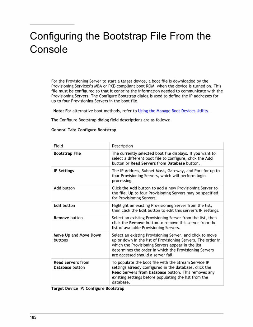
185
Configuring the Bootstrap File From theConsole
For the Provisioning Server to start a target device, a boot file is downloaded by theProvisioning Services’s MBA or PXE-compliant boot ROM, when the device is turned on. Thisfile must be configured so that it contains the information needed to communicate with theProvisioning Servers. The Configure Bootstrap dialog is used to define the IP addresses forup to four Provisioning Servers in the boot file.
Note: For alternative boot methods, refer to Using the Manage Boot Devices Utility.
The Configure Bootstrap dialog field descriptions are as follows:
General Tab: Configure Bootstrap
Field Description
Bootstrap File The currently selected boot file displays. If you want toselect a different boot file to configure, click the Addbutton or Read Servers from Database button.
IP Settings The IP Address, Subnet Mask, Gateway, and Port for up tofour Provisioning Servers, which will perform loginprocessing.
Add button Click the Add button to add a new Provisioning Server tothe file. Up to four Provisioning Servers may be specifiedfor Provisioning Servers.
Edit button Highlight an existing Provisioning Server from the list,then click the Edit button to edit this server’s IP settings.
Remove button Select an existing Provisioning Server from the list, thenclick the Remove button to remove this server from thelist of available Provisioning Servers.
Move Up and Move Downbuttons
Select an existing Provisioning Server, and click to moveup or down in the list of Provisioning Servers. The order inwhich the Provisioning Servers appear in the listdetermines the order in which the Provisioning Serversare accessed should a server fail.
Read Servers fromDatabase button
To populate the boot file with the Stream Service IPsettings already configured in the database, click theRead Servers from Database button. This removes anyexisting settings before populating the list from thedatabase.
Target Device IP: Configure Bootstrap

Use DHCP to retrievetarget device IP
Select this option to retrieve target device IP; defaultmethod.
Use static target device IP Selecting this method requires that a primary andsecondary DNS and Domain be identified.
Server Lookup: Configure Bootstrap
Use DNS Select this option to use DNS to find the server. The hostname displays in the Host name textbox. If this option isselected and the Use DHCP to retrieve Device IP option isselected (under Device IP Configuration settings), yourDHCP server needs to provide option 6 (DNS Server).
Note: If using HA, specify up to four Provisioning Serversfor the same Host name on your DNS server.
Use Static IP Use the static IP address of the Provisioning Server fromwhich to boot from. If you select this option, click Add toenter the following Provisioning Server information, thenclick OK to exit the dialog:
IP AddressSubnet MaskGatewayPort (default is 6910)
Note: If using HA, enter up to four Provisioning Servers. Ifyou are not using HA, only enter one. Use the Move Upand Move Down buttons to sort the Provisioning Serversboot order. The first Provisioning Server listed will be theserver that the target device attempts to boot from.
Options Tab: Configure Bootstrap
Verbose Mode Select the Verbose Mode option if you want to monitorthe boot process on the target device (optional) or viewsystem messages.
Interrupt Safe Mode Select Interrupt Safe Mode if you are having trouble withyour target device failing early in the boot process.
Advanced Memory Support This setting enables the bootstrap to work with newerWindows OS versions and is enabled by default. Onlydisable this setting on older XP or Windows Server OS 32bit versions that do not support PAE, or if your targetdevice is hanging or behaving erratically in early bootphase.
Configuring the Bootstrap File From the Console
186
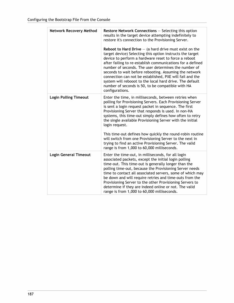
Network Recovery Method Restore Network Connections — Selecting this optionresults in the target device attempting indefinitely torestore it's connection to the Provisioning Server.
Reboot to Hard Drive — (a hard drive must exist on thetarget device) Selecting this option instructs the targetdevice to perform a hardware reset to force a rebootafter failing to re-establish communications for a definednumber of seconds. The user determines the number ofseconds to wait before rebooting. Assuming the networkconnection can not be established, PXE will fail and thesystem will rebooot to the local hard drive. The defaultnumber of seconds is 50, to be compatible with HAconfigurations.
Login Polling Timeout Enter the time, in milliseconds, between retries whenpolling for Provisioning Servers. Each Provisioning Serveris sent a login request packet in sequence. The firstProvisioning Server that responds is used. In non-HAsystems, this time-out simply defines how often to retrythe single available Provisioning Server with the initiallogin request.
This time-out defines how quickly the round-robin routinewill switch from one Provisioning Server to the next intrying to find an active Provisioning Server. The validrange is from 1,000 to 60,000 milliseconds.
Login General Timeout Enter the time-out, in milliseconds, for all loginassociated packets, except the initial login pollingtime-out. This time-out is generally longer than thepolling time-out, because the Provisioning Server needstime to contact all associated servers, some of which maybe down and will require retries and time-outs from theProvisioning Server to the other Provisioning Servers todetermine if they are indeed online or not. The validrange is from 1,000 to 60,000 milliseconds.
Configuring the Bootstrap File From the Console
187
Configuring the Bootstrap File1. In the Console, highlight the Servers folder in the tree, or highlight a Provisioning
Server, then select Configure bootstrap from the Action menu. The ConfigureBootstrap dialog appears.
Select the boot file that was copied to the directory you selected during theProvisioning Server setup.
Important:
If a previous version of Provisioning services was installed on this server, you mustchange the default location from:
C:\Program Files\<CitrixorOEMname>\Provisioning Services
to:
C:\Documents and Settings\All Users\Application Data\<Citrix or OEMname>\Provisioningservices\Tftpboot
If the default is not changed, the bootstrap file can not be configured from the Consoleand target devices will fail to boot; receiving a ‘Missing TFTP’ error message.
Note: If you installed the Console on a separate machine, select the path of theremote Provisioning Server (which has boot services installed).
2. Click Read DB. When the Stream Service starts, it creates a record in the database withits own IP address. There is only one Stream Service option record per database. If theservice is bound to multiple IP addresses, multiple records appear in the database. TheRead DB function chooses only one IP address from each Provisioning Server. Thisfunction can also be used to populate the boot file with the Stream Service IP settingsalready configured in the database.
3. Choose from the following options:
● Select the Verbose Mode option if you want to monitor the boot process on thetarget device (optional). This enables system messaging on the target device.
● Select Interrupt Safe Mode if the target device hangs early in the boot process.
● Select Advanced Memory Support option to enable the bootstrap to work withnewer Windows OS versions (enabled by default). Only disable this setting on olderXP or Windows Server OS 32 bit versions that do not support PAE, or if your targetdevice is hanging or behaving erratically in early boot phase.
4. Select from the following Network Recovery Methods:
● Restore Network Connections - Selecting this option results in the target deviceattempting indefinitely to restore it's connection to the Provisioning Server.
● Reboot to Hard Drive - Selecting this option instructs the target device to perform a hardware reset to force a reboot after failing to re-establish communications for a defined number of seconds. The user determines the number of seconds to wait before rebooting. Assuming the network connection can not be established, PXE will fail and the system will reboot to the local hard drive. The default number of
Configuring the Bootstrap File From the Console
188

seconds is 50. Click the Browse button to search for and select the folder created inStep 1, or enter a full path or UNC name.
Note: If the partition containing the vDisks is formatted as a FAT file system, amessage displays a warning that this could result in sub-optimal performance. It isrecommended that NTFS be used to format the partition containing the vDisks. Do notchange the address in the Port field.
Caution: All boot services (PXE, TFTP) must be on the same NIC (IP). But the StreamService can be on a different NIC. The Stream Service allows you to bind to multipleIPs (NICs).
5. Configure the following:
Login Polling Timeout
Enter the time, in milliseconds, between retries when polling for servers. Each server issent a login request packet in sequence. The first server that responds is used. Thistime-out simply defines how often to retry the single available server with the initiallogin request. This time-out defines how quickly the round-robin routine will switchfrom one server to the next, in trying to find an active server. The valid range is from1,000 to 60,000 milliseconds.
Login General Timeout
Enter the time-out, in milliseconds, for all login associated packets, except the initiallogin polling time-out. The valid range is from 1,000 to 60,000 milliseconds.
6. Click OK to save your changes.
Configuring the Bootstrap File From the Console
189

190
Using the Manage Boot Devices Utility
The Manage Boot Devices Utility provides an optional method for providing IP and bootinformation (boot device) to target devices; as an alternative to using the traditional DHCP,PXE, and TFTP methods. Using this method, when the target device starts, it obtains theboot information directly from the boot device. With this information, the target device isable to locate, communicate, and boot from the appropriate Provisioning Server. After theuser is authenticated, the Provisioning Server provides the target device with its vDiskimage.
Supported Boot Devices
The following boot devices are supported in this release:
Note: The Boot Device Management utility is not supported on operating systems olderthan, and including, Windows 2000. Wireless NICs are not supported.
● USB
● CD-ROM (ISO)
● Hard Disk Partition
Caution:
When an entire hard drive is selected as boot device, all existing disk partitions are erasedand re-created with a single active partition. The targeted partition is reserved as a bootdevice and cannot be used by the operating system or data.
When a hard disk partition is selected as boot device, the selected disk partition data isdeleted and set as an active partition. This active partition becomes the boot device.
Boot devices are configured using the Boot Device Management utility. The Manage BootDevices utility is structured as a wizard-like application, which enables the user to quicklyprogram boot devices.
After installing the boot device, complete the procedures that follow.
Configuring Boot Devices
● The vDisk must already be formatted and ready before the BDM.exe is run.
● If using the target device hard disk drive as the boot device, copy BDM. exe from theproduct installation directory on the server, into the product installation directory onthe target device.

● The target device settings in the Console should be set to boot from the vDisk but theactual device should be set to boot from hard disk first.
1. From C:\Program Files\Citrix\Provisioning Services product installation directory, runBDM.exe. The Boot Device Management window opens.
2. Under Server Lookup, select the radio button that describes the method to use toretrieve Provisioning Server boot information:
● Use DNS to find the Provisioning Server from which to boot from. If this option isselected and the Use DHCP to retrieve Device IP option is selected (under Device IPConfiguration settings), your DHCP server needs to provide option 6 (DNS Server)
Note: The boot device uses Host name plus DHCP option 15 (Domain Name, whichis optional) as the fully qualified domain name (FQDN) to contact the DNS serverto resolve the IP address.
If using HA, specify up to four Provisioning Servers for the same Host name on yourDNS server.
● Use the static IP address of the Provisioning Server from which to boot from. If youselect this option, click Add to enter the following Provisioning Server information,then click OK to exit the dialog:
● IP Address
● Port (default is 6910)If using HA, enter up to four Provisioning Servers. If you are not using HA, only enterone. Use the Move Up and Move Down buttons to sort the Provisioning Servers bootorder. The first Provisioning Server listed will be the server that the target deviceattempts to boot from.
3. Click Next. The Set Options dialog appears.
4. Configure the following local boot options, then click Next:
● Verbose Mode; enable/disables the displaying of extensive boot and diagnosticinformation that is helpful when debugging issues.
● Interrupt Safe Mode; enable/disable for debugging issues, which is sometimesrequired for drivers that exhibit timing or boot behavior problems.
● Advanced Memory Support; enables/disables the address extensions, to matchyour operating system settings. Select this option to enable the bootstrap to workwith newer Windows OS versions (enabled by default). Only disable this setting onolder XP or Windows Server OS 32 bit versions that do not support PAE, or if yourtarget device is hanging or behaving erratically in early boot phase.
● Network Recovery Method; select to attempt to restore the network connection orto reboot from a hard drive if the target device loses connection to the ProvisioningServer, and how long (in seconds) to wait to make this connection.
● Login Polling Timeout; in general, it is recommended that you start values of onesecond for each of the polling and general timeouts. You should extend these whenusing 3DES encryption. You should further extend the timers based upon workload.A reasonable setting for 100 target devices running triple DES in the network wouldbe three seconds.
Using the Manage Boot Devices Utility
191

● Login General Timeout; a reasonable setting for 100 target devices running tripleDES in the network would be ten Seconds for the General Timeout.
5. On the Burn the Boot Device dialog, configure the target device IP. If the Use DNS tofind the Server option is selected and your DHCP service does not provide option 6(DNS Server), then enter the following required information (note that the server namemust be less than 16 characters length and the domain name less than 48 characters inlength):
● Primary DNS Server Address
● Secondary DNS Server Address
● Domain Name6. Configure the Boot Deviceproperties.
● Add an active boot partition . Check this option to add a boot partition. Note: Aboot partition is required if booting from the device's hard drive (for example, whenselecting a XENPVDISK boot device with small partition or partition offset).
● Select the boot device from the list of devices.If a partition offset size is set, a confirmation message displays to confirm thedestination size. Type Yes (case sensitive) to continue.
7. If applicable, configure Media Properties.
8. Click Burn. A message appears to acknowledge that the boot device was successfullycreated. If selecting ISO format, use your CD burning software to burn the ISO image.
9. Click Exit to close the utility.
10. Boot the target device and enter the BIOS Setup. Under the Boot Sequence, move theboot device to the top of the list of bootable devices. Save the change, then boot thetarget device.
After the boot device is programmed, a target device boot sequence can be configuredusing the Console’s Target Device Disk Properties dialog. These boot behaviors are usedafter a target device connects to a Provisioning Server. The Console allows multiple vDiskimages to be assigned to a target device. The way in which these vDisks boot depends uponthe selected boot behavior.
When configuring the BIOS to work with the boot device (either USB or ISO image), it isimperative that the NIC PXE option is enabled. The PXE boot option is required in order forthe NIC Option ROM to stay resident in memory during the pre-boot process. This way, UNDIwill be available to the boot device to properly initialize the NIC. Otherwise, the "API notfound" message would be displayed by the boot device.
Using the Manage Boot Devices Utility
192
193
Configuring the BIOS EmbeddedBootstrap
This feature is OEM specific and provides end users with systems preconfigured withProvisioning Services, allowing customers to deploy an Provisioning Services-enabledenvironment with minimal effort. This feature becomes an alternative to the standard PXEboot method.
As part of this solution, the OEM embeds the bootstrap within the target device’s BIOS atthe factory. The OEM also pre-configures the device with product license keys.
For the BIOS-Embedded Bootstrap feature to work automatically from the factory, thetarget network must support the following:
● A DHCP server that is capable of providing the target device’s IP, Subnet & Gatewayaddress. Additionally, the DHCP service must provide the default DNS server for theclient to use.
● A DNS server must be active on the network
● A DNS entry must be defined which points the name <IMAGESERVER1> to eachProvisioning Server's active IP address. This DNS entry is used by the target device tofind an active server.
If the target device boots using the BIOS-Embedded Bootstrap, the configuration settingsare obtained from the device’s BIOS. These BIOS settings may indicate using DHCP with DNSto lookup the IP and server information (dynamic), or it may list up to four server IPaddresses in the BIOS (static).
The first time a target device boots, it reads the product license key and configurationinformation from the BIOS, locates the Stream Service, and then sends a device registrationmessage to the server. This message contains the information, in addition to theinformation inherited from the device collection template, necessary to add the device tothe Provisioning Services database.
Configuring the BIOS-Embedded Bootstrap SettingsThe OEM configures the BIOS-embedded bootstrap settings so that the bootstrap works‘out-of-the-box’. If the Provisioning Services administrator needs to change settings, usethe Configure BIOS Bootstrap feature in the Console. Configuration changes are updatedautomatically the next time the target device boots. However, only those BIOS settings thatdiffer from the new settings are updated.
Note: The target device must have enough information stored in the BIOS to make initialcontact with the Provisioning Server.
General Tab1. Right-click on a Provisioning Server in the Console window, then select the Configure
Bootstrap menu option. The Configure Bootstrap dialog appears.
2. To allow target device BIOS settings to be automatically updated if connected to thisserver, on the General tab, check the Automatically update the BIOS on the targetdevice with these settings check box. The next time the target device boots, thesesettings are automatically applied.
Target Device IP1. Select the Target Device IP tab on the Configure BIOS Bootstrap dialog.
2. Select from the following methods to use to retrieve target device IP addresses:
● Use DHCP to retrieve target device IP; default method.
● Use static target device IP; selecting this method requires that a primary andsecondary DNS and Domain be identified.
Server Lookup Tab1. On the Server Lookup tab, select the method that the target device will use to find the
Provisioning Server it will boot from:
Use DNS to find server
Select this option to find the server using DNS. The host name displays in the Hostname textbox.
Note: When using DNS, the DNS server must be able to resolve the name with theIP address of the server.
Use specific servers
Select this option to manually enter Provisioning Server data. If this informationwas not previously entered, no data appears. To quickly list all servers in thedatabase, click Read Servers from Database button.
To change or enter new information, click Edit, then manually enter theinformation in the Server Address dialog.
Note: Selecting the Reset to Default button will display a confirmation messageto indicating that automatic BIOS updates on the target devices will be disabledand to use DNS to find the server.
Configuring the BIOS Embedded Bootstrap
194
Options Tab1. On the Options tab, select from the network options that follow:
● Select the Verbose mode option if you want to monitor the boot process on thetarget device (optional). This enables system messaging on the target device.
● Select Interrupt safe mode if the target device hangs early in the boot process.
● Select the Advanced Memory Support option to enable the bootstrap to work withnewer Windows OS versions (enabled by default). Only disable this setting on olderXP or Windows Server OS 32 bit versions that do not support PAE, or if your targetdevice is hanging or behaving erratically in the early boot phase.
2. Select from the following Network Recovery Methods:
Restore network connections
Selecting this option results in the target device attempting indefinitely to restoreit's connection to the Provisioning Server.
Reboot to Hard Drive
Selecting this option instructs the target device to perform a hardware reset toforce a reboot after failing to re-establish communications for a defined number ofseconds. The user determines the number of seconds to wait before rebooting.Assuming the network connection can not be established, the target device will failto contact the server and the system will reboot to the local hard drive. The defaultnumber of seconds is 50.
Note: If the partition containing the vDisks is formatted as a FAT file system, amessage displays a warning that this could result in sub-optimal performance. It isrecommended that NTFS be used to format the partition containing the vDisks. Do notchange the address in the Port field.
Caution: All boot services must be on the same NIC (IP). But the Stream Service canbe on a different NIC. The Stream Service allows you to bind to multiple IPs (NICs).
3. Configure the following:
Login Polling Timeout
Enter the time, in milliseconds, between retries when polling for servers. Each server issent a login request packet in sequence. The first server that responds is used. Thistime-out simply defines how often to retry the single available server with the initiallogin request. This time-out defines how quickly the round-robin routine will switchfrom one server to the next, in trying to find an active server. The valid range is from1,000 to 60,000 milliseconds.
Login General Timeout
Enter the time-out, in milliseconds, for all login associated packets, except the initiallogin polling time-out. The valid range is from 1,000 to 60,000 milliseconds.
4. Click OK to save your changes.
Configuring the BIOS Embedded Bootstrap
195
196
Target Device Tasks
To manage and monitor target devices, choose from the following tasks:
● Preparing a Target Device for Imaging
● Creating New Target Device Entries in the Database
● Assigning vDisks
● Set the Target Device as the Template for this Collection
● Copy and Paste Target Device Properties
● Booting Target Devices
● Checking the Status of a Target Device From the Console
● Send Messages to Target Devices
● Disable a Target Device
● Deleting a Target Device
● Shutdown Target Devices
● Restart Target Devices
● Using the Virtual Disk Status Tray
● Managing Target Device Personality
● Create, Delete, Reset Active Directory Machine Accounts and Passwords
● Accessing Audit Information

197
Preparing a Master Target Device forImaging
A Master Target Device refers to a target device from which a hard disk image is built andstored on a vDisk. Provisioning Services then streams the contents of the vDisk created fromthe Master Target Device to other target devices.
● Preparing the Master Target Device’s Hard Disk
● Configuring a Master Target Device’s BIOS
● Configuring Network Adapter BIOS
● Installing Master Target Device Software
Preparing the Master Target Device's Hard DiskThe Master Target Device is typically different from subsequent target devices because itinitially contains a hard disk. This is the hard disk that will be imaged to the vDisk. Ifnecessary, after imaging, the hard disk can be removed from the Master Target Device.
In order to support a single vDisk, that is shared by multiple target devices, those devicesmust have certain similarities to ensure that the operating system has all required drivers.The three key components that must be consistent include the:
● Motherboard
● Network card, which must support PXE
● Video card
However, the Provisioning Services Common Image Utility allows a single vDisk tosimultaneously support different motherboards, network cards, video cards, and otherhardware devices.
If target devices will be sharing a vDisk, the Master Target Device serves as a ‘template’ forall subsequent diskless target devices as they are added to the network. It is crucial thatthe hard disk of Master Target Device be prepared properly and all software is installed onit in the proper order:
Note: Follow the instructions below after installing and configuring the ProvisioningServer and creating target devices.
Software must be installed on the Master Target Device in the order that follows:

1. Windows Operating System
2. Device Drivers
3. Service Packs Updates
4. Target Device Software
Applications can be installed before or after the target device software is installed. Iftarget devices will be members of a domain, and will share a vDisk, additional configurationsteps must be completed (refer to Managing Domain Accounts in the Administrator’s Guide,before proceeding with the installation).
Note: Dual boot vDisk images are not supported.
Configuring a Master Target Device's BIOSThe following steps describe how to configure the target devices system’s BIOS and the BIOSextension provided by the network adapter, to boot from the network. Different systemshave different BIOS setup interfaces – if necessary, consult the documentation that camewith your system for further information on configuring these options.
1. If the target device BIOS has not yet been configured, re-boot the target device andenter the system’s BIOS setup. (To get to BIOS setup, press the F1, F2, F10 or Deletekey during the boot process. The key varies by manufacturer).
2. Set the network adapter to On with PXE.
Note: Depending on the system vendor, this setting may appear differently.
3. Configure the target device to boot from LAN or Network first. Optionally, select theUniversal Network Driver Interface; UNDI first, if using a NIC with Managed Boot Agent(MBA) support.
Note: On some older systems, if the BIOS setup program included an option thatpermitted you to enable or disable disk-boot sector write protection, ensure that theoption is disabled before continuing.
4. Save changes, then exit the BIOS setup program.
5. Boot the target device from it’s hard drive over the network to attach the vDisk to thetarget device.
Configuring Network Adapter BIOSThis procedure is only necessary for older systems.
1. Re-boot the Master Target Device.
2. Configure the network adapter’s BIOS extension through setup.
During the system boot, the network adapter’s BIOS extension will present aninitialization message similar to the following: Initializing Intel ® BootAgent Version 3.0.03 PXE 2.0 Build 078 (WfM 2.0) RPL v2.43
Preparing a Master Target Device for Imaging
198

Enter the network adapter’s BIOS extension. (Consult the network adapter’sdocumentation.) The key combination for entering the network adapter’s BIOSextension varies by manufacturer. For example, to enter the Intel Boot Agent setupscreen, type Ctrl+S.
A screen similar to the following appears:
3. Change the boot order to Network first, then local drives.
4. Save any changes, and exit the setup program. In the Intel Boot Agent, typing F4 savesthe changes.
Alternatively, a device can be configured to provide IP and boot information (boot file) totarget devices using the Manage Boot Devices utility.
Installing Master Target Device SoftwareNote: It is recommended that you read the Release Notes document before installingtarget-device software. Before installing the product software on a Master Target Device,turn off any BIOS-based-virus protection features. To include anti-virus software on thevDisk image, be sure to turn the anti-virus software back on prior to running the ImagingWizard.
Provisioning Services target device software must be installed on a Master Target Deviceprior to building a vDisk image.
Provisioning Services target device software components include:
● Provisioning Services Virtual Disk, which is the virtual media used to store the diskcomponents of the operating system and applications.
● Provisioning Services Network Stack, which is a proprietary filter driver that is loadedover the NIC driver, allowing communications between the target devices and theProvisioning Server.
● Provisioning Services SCSI Miniport Virtual Adapter, which is the driver that allowsthe vDisk to be mounted to the operating system on the target device.
● Provisioning Services Imaging Wizard, use to create the vDisk file and image theMaster Target Device.
Preparing a Master Target Device for Imaging
199
● Virtual Disk Status Tray Utility, to provide general vDisk status and statisticalinformation. This utility includes a help system.
● Target Device Optimizer Utility, used to change target device setting to improveperformance.
Provisioning Services target device software is available for 32-bit and 64-bit Windowsoperating systems.
Installing Provisioning Services Target DeviceSoftware on a Windows Device
1. Boot the Master Target Device from the local hard disk.
2. Verify that all applications on the device are closed.
3. Double-click on the appropriate installer. The product installation window appears.
4. On the Welcome dialog that displays, click Next, scroll down to the end, then acceptthe terms of the license agreement.
5. Click Next to continue, the Customer Information dialog appears.
6. Type your user name and organization name in the appropriate text boxes.
7. Select the appropriate install user option. The option you select depends on if thisapplication will be shared by users on this computer, or if only the user associated withthis computer should have access to it.
8. Click Next, the Destination Folder dialog appears.
9. Click Next to install the target device to the default folder (C:\ProgramFiles\Citrix\Provisioning Services). Optionally, click Change, then either enter thefolder name or navigate to the appropriate folder, and then click Next, then clickInstall. The installation status information displays in the dialog.
Note: The installation process may take several minutes. While the installationprocess is running, you can click Cancel to cancel the installation and roll-back anysystem modifications. Close any Windows Logo messages that appear.
10. The 'Installation Wizard Completed' message displays in the dialog when thecomponents and options have successfully been installed. Close the wizard window. Ifboth .NET 3.0 SP1 or newer is installed and Windows Automount is enabled, the ImagingWizard will start automatically by default (for details, refer to Image Wizard).
Note: If a Windows reboot request message displays before the imaging processcompletes, ignore the request until imaging completes successfully.
11. Reboot the device after successfully installing product software and building the vDiskimage.
Preparing a Master Target Device for Imaging
200
201
Adding Target Devices to the Database
To create new target device entries in the Provisioning Services database, select one of thefollowing methods:
● Using the Console to Manually Create Target Device Entries
● Using Auto-add to Create Target Device Entries
● Importing Target Device Entries
After the target device exists in the database, you can assign a vDisk to the device. Refer toassign a vDisk to the device for more details.
Using the Console to Manually Create Target DeviceEntries
1. In the Console, right-click on the Device Collection where this target device is tobecome a member, then select the Create Device menu option. The Create Devicedialog appears.
2. Type a name, description, and the MAC address for this target device in the appropriatetext boxes.
Note: If the target device is a domain member, use the same name as in the Windowsdomain. When the target device boots from the vDisk, the machine name of thedevice becomes the name entered. For more information about target devices andActive Directory or NT 4.0 domains, refer to “Enabling Automatic PasswordManagement”
3. Optionally, if a collection template exists for this collection, you have the option toenable the checkbox next to Apply the collection template to this new device.
4. Click the Add device button. The target device inherits all the template propertiesexcept for the target device name and MAC address.
5. Click OK to close the dialog box. The target device is created and assigned to a vDisk
Importing Target Devices EntriesTarget device entries can be imported into any device collection from a .csv file. Theimported target devices can then inherit the properties of the template target device thatis associated with that collection. For more details, refer to Importing Target Devices intoCollections.
202
Using the Auto-Add Wizard
The Auto-Add Wizard automates the configuration of rules for automatically adding newtarget devices to the Provisioning Services database using the Auto-Add feature.
The Auto-Add Wizard can be started at the Farm, Site, Collection or Device level. Whenstarted at a level lower than Farm, the wizard uses that choice as the default choice. Forexample, if it is started on a particular target device, it will:
● Select the Site for that Device as the Default Site choice in the combo-box.
● Select the Collection for that Device as the Default Collection choice in the combo-box.
● Select that Device as the Template Device choice in the combo-box.
The wizard displays each page with choices pre-selected based on the location that theAuto-Add Wizard was started from.
A Farm Admininistrator has the ability to turn Auto-Add on or off and to select the defaultSite.
A Site Admininistrator only has the ability to select the default site if the current defaultsite is a site in which that administrator is the Site Administrator. If the Site Administratoris not the Administrator of the currently selected default Site, then that administrator canonly configure the sites they has access to.
To configure Auto-Add settings (the default collection of a site, template device for thedefault collection and target device naming rules):
1. On the Console, right-click on the farm, then select the Auto-Add wizard. The Welcometo the Auto-Add Wizard page appears.
2. Click Next. The Enable Auto-Add dialog appears.
Note: Only a farm administrator can change settings on this page.
3. Check the box next to Enable Auto-Add to enable this feature, then click Next. TheSelect Site page appears.
Note: Site administrators can only select sites to which they have permissions.
4. From the Site drop-down list, select the site where devices should be added, thenselect Next. The Select Collection page displays with the default collection selected.
5. Accept the default collection or select a different collection from the Collectiondrop-down list, then click Next. The Select Template Devices page appears.
6. Select the device to use as a template, so that new devices being added will inherit theexisting target device's basic property settings, then click Next.
7. To view the selected device's properties, click Properties. A read-only dialog displaysthe selected device's properties. Close the dialog after reviewing the properties.

8. Click Next. The Device Name page displays.
9. Enter a static prefix that helps identify all devices that are being added to thiscollection. For example: 'Boston' to indicate devices located in Boston.
Note: The prefix can be used in combination with the suffix, but is not required if asuffix is provided. The entire device name can have a maximum of 15 characters (theprefix length + number length + suffix length). For example, the following devicenames are considered valid:
● Boston000Floor2 (prefix, incrementing number length, and suffix provided; themaximum of 15 characters has been reached)
● Boston000 (no suffix is provided)
● 000Floor2 (no prefix is provided)The prefix cannot end with a digit.
10. Enter the length of the incrementing number to associate with the devices being addedto this collection. This number is incremented as each device is added. For example, ifthe number length is set to '3', Provisioning Services starts naming at '001' and stopsnaming or adding devices after the number reaches '999'.
Note: Enable the Zero fill option to automatically add the necessary number ofpreceeding zeros to a numbers length. For example, if the numbers length is set to'4', than the first target device number would be assigned as '0001'.
The number length must have a minimum of three digits and a maximum of 9 digits.
11. Enter a static suffix that helps to identify all devices being added to this collection. Forexample: Boston001Floor2 might be helpful to indicate the floor where these devicesreside.
The suffix can be used in combination with the prefix, but is not required if a prefix isprovided.
The entire device name can have a maximum of 15 characters (the prefix length +number length + suffix length).
The suffix cannot start with a digit.
The prefix and suffix combination must be unique in each collection.
12. Click Next. The Finish dialog appears.
13. Review all Auto-Add wizard settings, then click Finish. Auto-Add is now configured.
Using the Auto-Add Wizard
203

204
Assigning vDisks to Target Devices
A vDisk can be assigned to a single target device or to all devices within a target devicecollection. If a target device has more than one vDisk assigned to it, a list of vdisks displaysat boot time allowing the user to select the appropriate vDisk to boot.
Note: If one or more versions exist for a vDisk, the version target devices use inProduction is either the highest numbered production version or an override version. Fordetails refer to 'Accessing a vDisk Version' in the Administrator's Guide. For Maintenanceand Test devices, the State of any non-production versions are labeled.
Assigning vDisks to a target device
vDisks can be assigned to a single target device using:
● Drag-and-drop
● Target Device Properties dialog
Note: A vDisk cannot be assigned to a target device using drag-and-drop if that targetdevice was assigned a personal vDisks using the XenDesktop Wizard. A message dialogdisplays if a vDisk is dragged and dropped onto a collection that contains one or moretarget devices that use personal vDisks. The dialog provides the option to continue byacknowledging that the vDisk being assigned will only be assigned to those devices thatare not currently assigned a personal vDisk. Also, target devices that use personal vDiskscannot inherit the properties of a target device that doesn't use a personal vDisk(copy/paste).
To assign a vDisk, using drag-and-drop, to one or all target devices within a collection:
1. In the Console tree, expand the vDisk Pool within a given site or expand Stores todisplay the vDisk to be assigned in the right pane of the window.
2. Left-click and hold the mouse on the vDisk, then drag and drop it onto the target deviceor onto the collection.
To assign one or more vDisks to a single target device from the Target Device Propertiesdialog:
1. In the Console tree, expand the Device Collections folder, then click on the collectionfolder where this target device is a member. The target device displays in the detailspane.
2. Right-click on the target device, then select Properties. The Target Device Propertiesdialog appears.
3. On the General tab, select the boot method that this target device should use from theBoot from drop-down menu options.

4. On the vDisks tab, select the Add button within the vDisk for this Device section. TheAssign vDisks dialog appears.
5. To locate vDisks to assign to this target device, select a specific store or server underthe Filter options, or accept the default settings, which includes All Stores and AllServers.
6. In the Select the desired vDisks list, highlight the vDisk(s) to assign, then click OK,then OK again to close the Target Device Properties dialog.
Assigning vDisks to Target Devices
205

206
Set the Target Device as the Template forthis Collection
A target device can be set as the template for new target devices that are added to acollection. A new target device inherits the properties from the template target device,which allows you to quickly add new devices to a collection.
Note: Target devices that use personal vDisks are created and added to a collection whenthe XenDesktop Setup Wizard is run. If a target device template exists, it is ignored whenthe target device that uses a personal vDisk is added to the collection.
To set a target device as the template device for a collection, in the Console, right-click onthe target device, then select Set device as template.
Note: Disable the target device that serves as the template to permit all target devicesusing this template to be added to the database, but not permit the target device toboot. Target devices receive a message requesting that they first contact theadministrator before being allowed to boot. A ‘T’ appears in light blue on the deviceserving as the template. New target devices automatically have a name generated and allother properties will be taken from the default template target device. No userinteraction is required.

207
Copy and Paste Target Device Properties
To copy the properties of one target device, and paste those properties to other targetdevice members:
Note: Target devices that use personal vDisks can only inherit the properties of anothertarget device that uses a personal vDisk.
1. In the Console’s details pane, right-click on the target device that you want to copyproperties from, then select Copy device properties. The Copy Device Propertiesdialog appears.
2. Select the checkbox next to the properties that you want to copy, then click Copy. Theproperties are copied to the clipboard and the dialog closes.
3. Right-click on one or more target devices that will inherit the copied properties, thenselect the Paste menu option. The Paste Device Properties dialog appears.
4. Click Close to close the dialog.
208
Booting Target Devices
To boot target devices:
1. Right-click on a collection to boot all target devices in the collection, or highlight onlythose target devices that you want to boot within the collection tree, then select theBoot devices menu option. The Target Device Control dialog displays with the Bootdevices menu option selected in the Settings drop-down menu.
2. Click the Boot devices button to boot target devices. The Status column displays theBoot Signal status until the target device successfully receives the signal, then statuschanges to Success.
209
Checking a Target Device's Status fromthe Console
The target device status indicates whether it is currently active or inactive on the network.
To check the status of a target device:
1. Double-click on the target device in the Console window, then select the Propertiesmenu option. The Device Properties tab appears.
2. Select the Status tab and review the following status information:
● Current status (active or inactive)
● IP address
● Current Provisioning Server
● Current vDisk name
● Provisioning Server cache file size in bytesAlso, in the Console window, if the target device is active, the target device iconappears as a green computer screen. If the target device is inactive, the icon appearsas a black computer screen.
210
Sending Messages to Target Devices
To send a message to target devices members:
1. Right-click on the collection to send a message to all members within the collection, orhighlight only those target devices within the collection that should receive themessage, then select the Send message menu option. The Target Device Control dialogdisplays with the Message to devices menu option selected in the Settings drop-downmenu. Target devices are display in the Device table.
2. Type a message to display on target devices in the Message text box.
3. Click the Send message button. The Status column displays the Message Signal statusuntil target devices successfully receives the message, the status changes to Success.
211
Disabling a Target Device
The Disable Target Device feature prevents a new target devices from booting. Whenenabled, each time a new target device boots, if the Auto-add option is enabled, a newrecord is automatically created in the database and the following message appears on thetarget device:
This target device has been disabled. Please Contact your systemadministrator.
Once contacted, the system administrator can validate the target device. After theadministrator disables the option, the target device can boot successfully.
To disable or enable a target device, in the Console, right-click on the target device, thenselect the Disable or Enable menu option.
Note: Enable the Disable target device option on the template target device, to disableall target devices as they are added to a collection.

212
Deleting Target Devices
To delete a target device:
1. In the Console, right-click on the target devices you want to delete within thecollection (multiple selections can be made in the Details view), then select the Deletemenu option.
2. Click Yes to confirm the delete request. The target device is deleted from thecollection and any associated views. However, the vDisk image file for the target devicestill exists.

213
Shutting Down Target Devices
To shutdown target devices:
1. Right-click on the collection to shut down all target devices within the collection, orhighlight only those target devices that should be shut-down within a collection, thenselect the Shutdown devices menu option. The Target Device Control dialog displayswith the Shutdown devices menu option selected in the Settings drop-down menu.Target devices display in the Device table.
2. Type the number of seconds to wait before shutting down target devices in the Delaytext box.
3. Type a message to display on target devices in the Message text box.
4. Click the Shutdown devices button to shutdown target devices. The Status columndisplays the shutdown signal status until the target device shuts down. As each targetdevice successfully shuts down, the status changes to Success.

214
Restarting Target Devices
To restart target devices:
1. Right-click on a collection in the Console tree or highlight only those target devices thatshould be restarted within the collection, then select the Restart devices menu option.The Target Device Control dialog displays with the Restart devices menu optionselected in the Settings drop-down menu. Target devices display in the Device table.
2. Type the number of seconds to wait before restarting target devices in the Delay textbox.
3. Type a message to display on target devices in the Message text box.
4. Click the Restart devices button to restart target devices. The Status column displaysthe Restart Signal status until the target device successfully receives the signal, thenstatus changes to Success.
215
Moving Target Devices BetweenCollections
A target device can be moved from one collection to another collection within a site usingdrag and drop in the Console’s details pane (drag the device(s) from one collection, thendrop the device into another collection). Alternatively, target devices can be moved usingthe Move menu option.
To move a target device using the Move menu option:
1. In the Console, expand the collection, right-click on the target device in the detailspane, then select the Move menu option.
2. From the drop-down menu, select the collection to move this target device into. Ifapplicable, apply the collection’s device template to the target device being moved, byenabling Apply target collection’s template device properties to moved devices.
3. Click Move.
216
Using the Status Tray on a Target Device
The Virtual Disk Status Tray provides device and product edition information on the targetdevice. The purpose of this tool is to aid in the management and troubleshooting of vDisks.
Note: This tool is installed automatically during the installation process.
Using the Virtual Disk Status Tray includes the following tasks:
● Starting the Virtual Disk Status Tray
● Using the General Tab
● Using the Statistics Tab
● Setting Virtual Disk Status Tray Preferences
Starting the Virtual Disk Status TrayTo manually start the Virtual Disk Status tray, double-click on the Status Tray icon in theSystem Tray. The Virtual Disk Status Tray dialog appears.
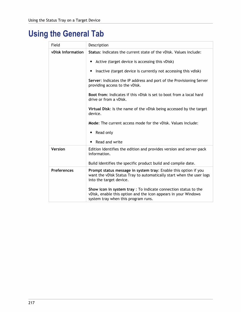
Using the General TabField Description
vDisk Information Status: Indicates the current state of the vDisk. Values include:
● Active (target device is accessing this vDisk)
● Inactive (target device is currently not accessing this vdisk)
Server: Indicates the IP address and port of the Provisioning Serverproviding access to the vDisk.
Boot from: Indicates if this vDisk is set to boot from a local harddrive or from a vDisk.
Virtual Disk: Is the name of the vDisk being accessed by the targetdevice.
Mode: The current access mode for the vDisk. Values include:
● Read only
● Read and write
Version Edition Identifies the edition and provides version and server-packinformation.
Build Identifies the specific product build and compile date.
Preferences Prompt status message in system tray: Enable this option if youwant the vDisk Status Tray to automatically start when the user logsinto the target device.
Show icon in system tray : To indicate connection status to thevDisk, enable this option and the icon appears in your Windowssystem tray when this program runs.
Using the Status Tray on a Target Device
217
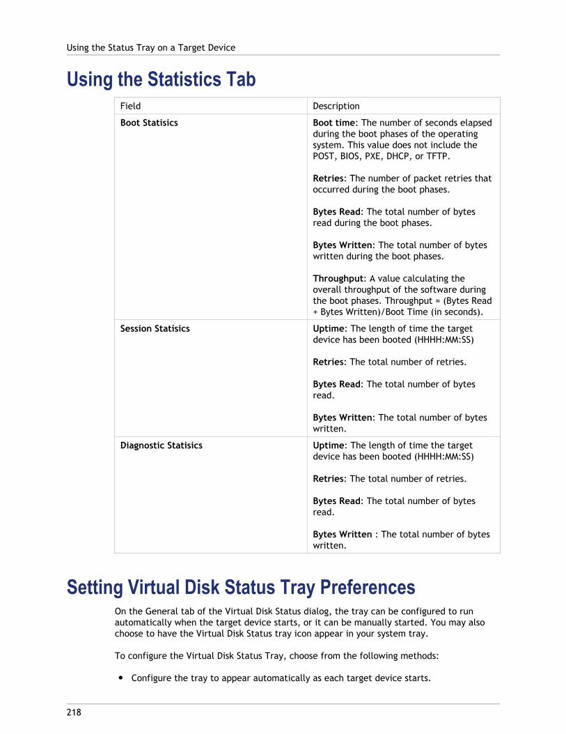
Using the Statistics TabField Description
Boot Statisics Boot time: The number of seconds elapsedduring the boot phases of the operatingsystem. This value does not include thePOST, BIOS, PXE, DHCP, or TFTP.
Retries: The number of packet retries thatoccurred during the boot phases.
Bytes Read: The total number of bytesread during the boot phases.
Bytes Written: The total number of byteswritten during the boot phases.
Throughput: A value calculating theoverall throughput of the software duringthe boot phases. Throughput = (Bytes Read+ Bytes Written)/Boot Time (in seconds).
Session Statisics Uptime: The length of time the targetdevice has been booted (HHHH:MM:SS)
Retries: The total number of retries.
Bytes Read: The total number of bytesread.
Bytes Written: The total number of byteswritten.
Diagnostic Statisics Uptime: The length of time the targetdevice has been booted (HHHH:MM:SS)
Retries: The total number of retries.
Bytes Read: The total number of bytesread.
Bytes Written : The total number of byteswritten.
Setting Virtual Disk Status Tray PreferencesOn the General tab of the Virtual Disk Status dialog, the tray can be configured to runautomatically when the target device starts, or it can be manually started. You may alsochoose to have the Virtual Disk Status tray icon appear in your system tray.
To configure the Virtual Disk Status Tray, choose from the following methods:
● Configure the tray to appear automatically as each target device starts.
Using the Status Tray on a Target Device
218

● Add the Virtual Disk Status tray icon to your system tray.
Configuring the tray to appear automatically as each target device starts
1. Start the Virtual Disk Status Tray, and then select the General tab.
2. Select the Automatically start this program checkbox under Preferences. The tray startsautomatically the next time the target device boots.
Adding the Virtual Disk Status tray icon to your system tray
1. Start the Virtual Disk Status tray, and then select the General tab.
2. Select the Show icon in System Tray checkbox under Preferences. The Virtual DiskStatus tray icon appears in your system tray the next time the target device boots.
Using the Status Tray on a Target Device
219
220
Managing Target Device Personality
Normally, all target device’s sharing the same vDisk must have identical configurations. TheTarget Device Personality feature allows you to define data for specific target devices andmake it available to the target device at boot time. This data can then be used by yourcustom applications and scripts for a variety of purposes.
For example, suppose you are using Provisioning Server to support PCs in three classrooms.Each classroom has its own printer, and you want the PCs in each classroom to default tothe correct printer. By using the Target Device Personality feature, you can define a defaultprinter field, and then enter a printer name value for each target device. You define thefield and values under Target Device Properties. This information is stored in the database.When the target device boots, the device-specific printer information is retrieved from thedatabase and written to an .INI file on the vDisk. Using a custom script or application thatyou develop, you can retrieve the printer value and write it to the registry. Using thismethod, each time a target device boots, it will be set to use the correct default printer inits classroom.
The number of fields and amount of data that you can define for each target device islimited to 64Kb or 65536 bytes per target device. Each individual field may be up to 2047bytes.
Target Device Personality Tasks
● Define personality data for a single target device using the Console
● Define personality data for multiple target device using the Console
● Using Target Device Personality Data
Define personality data from a single target deviceusing the Console
To define personality data for a single target device:
1. In the Console, right-click on the target device that you want to define personality datafor, then select the Properties menu option.
2. Select the Personality tab.
3. Click the Add button. The Add/Edit Personality String dialog appears.
Note: There is no fixed limit to the number of field names and associated strings you can add. However, the limits to the total amount of personality data assigned to a single string (names and data combined) is approximately 2047 bytes. Also, the total amount of data contained in names, strings and delimiters is limited to approximately 64Kb or 65536 bytes per target device. This limit is checked by the administrator
when you attempt to add a string. If you exceed the limit, a warning messagedisplays and you are prevented from creating an invalid configuration.
Target device personality data is treated like all other properties. This data will beinherited when new target devices are added automatically to the database by eitherthe Add New Target Device Silently option, or with the Add New Target Device withBIOS Prompts option.
4. Enter a name and string value.
Note: You can use any name for the field Name, but you cannot repeat a field namein the same target device. Field names are not case sensitive. In other words, thesystem interprets “FIELDNAME” and “fieldname” as the same name. Blank spacesentered before or after the field name are automatically removed. A personalityname cannot start with a $. This symbol is used for reserved values such as$DiskName and $WriteCacheType.
5. Click OK.
To add additional fields and values, repeat Steps 5 and 6 as needed. When finished addingdata, click OK to exit the Target Device Properties dialog.
Define personality data for multiple target deviceusing the Console
Define target device personality for multiple devices:
1. In the Console, right-click on the target device that has the personality settings thatyou want to share with other device, then select Copy. The Copy device propertiesdialog appears.
2. Highlight the target devices in the details pane that you want to copy personalitysettings to, then right-click and select the Paste device properties menu.
3. Click on the Personality strings option (you may also choose to copy other properties atthis time), then click Paste.
Using Target Device Personality DataOnce the file system becomes available to the target device, the personality data is writtento a standard Windows .ini text file called Personality.ini. The file is stored in the rootdirectory of the vDisk file system for easy access by your custom scripts or applications.
The file is formatted as follows:
[StringData]FieldName1=Field data for first fieldFieldName2=Field data for second field
Managing Target Device Personality
221
This file is accessible to any custom script or application. It can be queried by the standardWindows .INI API. Additionally, a command line application, called GetPersonality.exe, isprovided to allow easier batch file access to the personality settings.A target device’s vDisk name and mode can be retrieved using GetPersonality.exe. Thefollowing reserve values are included in the [StringData] section of the Personality.ini file:
$DiskName=<xx>$WriteCacheType=<0 (Private image)All other values are standard image; 1 (Server Disk), 2 (Server Disk Encrypted), 3 (RAM), 4 (Hard Disk), 5 (Hard Disk Encrypted), 6 (RAM Disk), or 7 (Difference Disk). Min=0, Max=7, Default=0>
The xx is the name of the disk. A vDisk name cannot start with a $. This symbol is used forreserved values such as $DiskName and $WriteCacheType. The following message displays ifa name that starts with $ is entered:
A name cannot start with a $. This is used for reserve values like $DiskName and $WriteCacheType. The $DiskName and $WriteCacheType values can be retrieved on the target device using GetPersonality.exe.
GetPersonality.exe
The command line utility GetPersonality.exe allows users to access the Target DevicePersonality settings from a Windows batch file. The program queries the INI file for the userand places the personality strings in the locations chosen by the user. GetPersonality.exesupports the following command line options:
GetPersonality FieldName /r=RegistryKeyPath <- Place field in registryGetPersonality FieldName /f=FileName <- Place field in fileGetPersonality FieldName /o <- Output field to STDOUTGetPersonality /? or /help <- Display help
Examples
Setting a Registry Key Value:
The example below retrieves the Target Device Personality data value from theDefaultPrinter field and writes it to the target device registry to set the default printer forthe device.
The Target Device Personality String Set in Target Device Properties is:
DefaultPrinter= \\CHESBAY01\SAVIN 9935DPE/2035DPE PCL 5e,winspool,Ne03:
A batch file run on the target device would include the following line:GetPersonality DefaultPrinter /r=HKEY_CURRENT_USER\Software\Microsoft\Windows NT\CurrentVersion\Device
Note: The actual key name should be the UNC name of the network printer, such as\\dc1\Main, and the value that should be entered for the key would be similar towinspool,Ne01: where Ne01 is a unique number for each installed printer.
Setting Environment Variables:
Setting environment variables with personality data is a two-step process:
1. Use the GetPersonality command with the /f option to insert the variable into atemporary file.
Managing Target Device Personality
222
2. Use the set command to set the variable. For example, to set the environment variablePath statement for the target device a personality name, define the Pathname with thestring value:
%SystemRoot%;%SystemRoot%\System32\Wbem;C:\Program Files\Microsoft Office\OFFICE11\;C:\Program Files\Microsoft SQL Server\80\Tolls\Binn
The /f option creates a temporary file, allowing for a name to be assigned, in this casetemp.txt. The following lines would then need to be included in the batch file:GetPersonality Pathname /f=temp.txtset /p Path= <temp.txt
Note: If the filename specified with the /f option already exists, GetPersonality willnot append the line to the file. Instead, the existing line is overwritten in the file.
Managing Target Device Personality
223
224
Target Device Properties
Note: A reboot is required if a target device is active when modifications are made to anyof the following device properties:
● Boot from
● MAC
● Port
● vDisks for this Device
The following tables define the properties associated with a target device, which includes:
● General tab
● vDisk tab
● Personality tab
● Status tab
● Authentication tab
● Logging
General TabName
The name of the target device or the name of the person who uses the target device.The name can be up to 15 bytes in length. However, the target device name cannot bethe same as the machine name being imaged.
Note: If the target device is a domain member, use the same name as in the Windowsdomain, unless that name is the same as the machine name being imaged. When thetarget device boots from the vDisk, the name entered here becomes the target devicemachine name.
Description
Provides a description to associate with this target device.
Type
Select the access type for this target device from the drop-down list, which includes thefollowing options:
Maintenance select this option to use this target device as a Maintenance device whichwill to apply updates to a new maintenance version of a vDisk. A Maintenance device hasexclusive read-write access to a maintenance version.
Test select this option to use this target device to access versions that are in Test mode.Test devices have shared read-only access to the test versions of a vDisk in order tofacilitate QA testing of a vDisk version in Standard Image mode, prior to the release ofthat version to production machines.
Production select this option to allow the target device to stream an assigned vDisk thatis currently in production. Production devices have shared, read-only access toproduction versions of a vDisk. Production devices do not have access to maintenance ortest versions, which prevents updates that have not been tested from accidentally beingdeployed on production machines.
The default Type for a new device is Maintenance. The default Type for an existingdevice is Maintenance.
Boot from
The boot method this target device should use. Options include booting from a vDisk,hard disk, or floppy disk.
MAC
Enter the media access control (MAC) address of the network interface card that isinstalled in the target device.
Port
Displays the UDP port value.
In most instances, you do not have to change this value. However, if target devicesoftware conflicts with any other IP/UDP software (that is, they are sharing the sameport), you must change this value.
Class
Class used for matching new vDisks to target devices when using Automatic Disk ImageUpdate in order to match new vDisks images to the appropriate target devices.
Disable this device
Enable this option to prevent target devices from booting. Regardless if enabled ordisabled, new target devices that are added using Auto-add, have records created in thedatabase.
vDisk TabvDisks for this Device
Displays the list of vDisk assigned to this target device.
Target Device Properties
225
Click Add to open the Assign vDisks dialog. To filter the vDisks that display, select aspecific store name and Provisioning Server or select All Stores and All Servers to list allvDisks available to this target device. Highlight the vDisks to assign, then click OK.
Click Remove to remove vDisks from this device.
Click Printers to open the Target Devices vDisk Printers dialog. This dialog allows you tochoose the default printer and any network and local printers to enable or disable forthis target device.
Personality TabOptions
Provides secondary boot options:
● Include the local hard drive as a boot device.
● Include one or more custom bootstraps as boot options.If enabling a custom bootstrap, click Add, to enter the bootstrap file name and the menutext to appear (optional), then click OK.
If more than one vdisk is listed in the table or if either (or both) secondary boot optionsare enabled, the user is prompted with a disk menu at the target devices when it isbooted. Enter a menu option name to display to the target device. The target device canselect which boot options to use.
Click Edit to edit an existing custom bootstrap's file name or menu text.
Click Remove to remove a custom bootstrap file from those available to this targetdevice.
Name and String
There is no fixed limit to the number of names you can add. However, the maximumname length is 250 characters and the maximum value length is 1000 characters.
Use any name for the field Name, but do not repeat a field name in the same targetdevice. Field names are not case sensitive. In other words, the system interprets“FIELDNAME” and “fieldname” as the same name. Blank spaces entered before or afterthe field name are automatically removed.
A personality name cannot start with a $. This symbol is used for reserved values such as$DiskName and $WriteCacheType.
Authentication TabPassword information entered in this dialog is for initial target device login only. It does notaffect Windows account login.
Target Device Properties
226
Authentication
If authenticating with a user name and password, enter the user name for the account.Follow your organization's user name conventions.
Note: Requires user names be at least two characters and no more than 40 charactersin length. User names are NOT case sensitive.
Authentication methods include:
● None
● Username and password
● External verification (user supplied method)Username
If the account already exists, you cannot change the user name.
Password
If authenticating with a user name and password:
Click the Change button to open the Change Password dialog. To create a new passwordfor a user account, type the old password, then type the new password in both the Newpassword and Confirm new password text boxes. Click OK to change the password.
Note: Follow your organization's password conventions. Requires passwords be at leastthree characters and no more than 20 characters in length. Passwords ARE casesensitive. Re-enter the new password exactly as you entered it in the previous field toconfirm it.
Status TabTarget Device Status
The following target device status information appears:
● Status: current status of this device (active or inactive).
● IP Address: provides the IP Address or 'unknown'.
● Server: the Provisioning Server that is communicating with this device.
● Retries: the number of retries to permit when connecting to this device.
● vDisk: provides the name of the vDisk or displays as 'unknown'.
● vDisk version: version of this vDisk currently being accessed.
● vDisk full name: the full file name for the version currently being accessed.
● vDisk access: identifies if the version is in Production, Maintenance, or Test.
Target Device Properties
227
● License information; depending on the device vendor, displays product licensinginformation (including; n/a, Desktop License, Datacenter License, XenApp License,or XenDesktop License).
Logging tabLogging level
Select the logging level or select Off to disable logging:
● Off – Logging is disabled for this Provisioning Server.
● Fatal– logs information about an operation that the system could not recover from.
● Error logs information about an operation that produces an error condition.
● Warning– logs information about an operation that completes successfully, but thereare issues with the operation.
● Info – Default logging level. Logs information about workflow, which generallyexplains how operations occur.
● Debug – logs details related to a specific operation and is the highest level oflogging. If logging is set to DEBUG, all other levels of logging information aredisplayed in the log file.
● Trace – logs all valid operations.
Target Device Properties
228
229
Managing vDisks
vDisks are managed throughout the vDisk lifecycle. Provisioning Services provides supportfor a full image lifecycle that takes a vDisk from initial creation, through deployment andsubsequent updates, and finally to retirement.The lifecycle of a vDisk consists of fourstages:
1. Creating
2. Deploying
3. Updating
4. Retiring
Creating a vDisk
Creation of a vDisk requires preparing the master target device for imaging, creating andconfiguring a vDisk file where the vDisk will reside, and then imaging the master targetdevice to that file; resulting in a new base vDisk image. This process can be performedautomatically, using the Imaging Wizard, or manually. Provisioning Services also providesthe option to create a commom image for use with a single target platform or for use withmultiple target platforms. For details, refer to Creating vDisks.
Deploying a vDisk
After a vDisk base image is created, it is deployed by assigning it to one or more devices. Adevice can have multiple vDisk assignments. When the device starts, it boots from anassigned vDisk. There are three boot mode options; Private Image mode (single deviceaccess, read/write), Standard Image mode (multiple device access, write cache options).For more details, refer to Deploying vDisks.
Updating a vDisk
It is often necessary to update an existing vDisk so that the image contains the most currentsoftware and patches. Updates can be made manually, or the update process can beautomated using vDisk Update Management features. Each time a vDisk is updated a newversion is created. Different devices can access different versions based on the type oftarget device and version classification. A maintenance device can have exclusiveread/write access to the newest maintenance version; test devices can have sharedread-only access to versions classified as test versions, and production devices can haveshared read-only access to production versions. Versions are created and managed from thevDisk Versioning Dialog. An update can also be the result of merging versions. For moredetails on updating vDisks, refer to Updating vDisks.
Retiring a vDisk
Retiring a vDisk is the same as deleting. The entire VHD chain including differencing andbase image files, properties files, and lock files are deleted. For details, refer to Retiring avDisk.

Note: In addition to those vDisk tasks performed within a vDisk's lifecycle, there are alsoother vDisk maintenance tasks that can be performed, such as importing or exporting thevDisk, backing-up vDisks, replicating, and load balancing.
Managing vDisks
230
231
Creating vDisks
This section provides the information and tasks necessary to create a new base vDisk image.
vDisks act as a hard disk for a target device and exist as disk image files on a ProvisioningServer or on a shared storage device. A vDisk consists of a VHD base image file, anyassociated properties files (.pvp), and if applicable, a chain of referenced VHD differencingdisks (.avhd).
When creating a vDisk image file, keep the following facts in mind:
● You can create as many vDisk image files as needed, as long as you have enough spaceavailable on the Provisioning Server, or on the storage device containing the vDiskimage files.
● vDisk files use FAT or NTFS file systems for Microsoft operating systems.
● Depending upon the file system used to store the vDisk, the maximum size of a VHD file(vDisk) is 2 terabytes (NTFS) or 4096MB (FAT).
● A vDisk may be shared (Standard Image) by one or more target devices, or it can existfor only one target device to access (Private Image).
Creating a new vDisk is the first stage in the lifecycle of a vDisk. To create a vDisk basicallyrequires preparing the master target device for imaging, creating and configuring a vDiskfile where the vDisk will reside, and then imaging the master target device to that file;resulting in a new base vDisk image. This process can be performed automatically, using theImaging Wizard, or manually. Provisioning Services also provides the option to create acommom image for use with a single target platform or for use with multiple targetplatforms.
Note: Your administrator role determines what displays and which tasks you can performin the Console. For example, you can view and manage vDisks in sites in which you are asite administrator. However, unless the farm administrator sets a site as the owner of astore, the site administrator can not perform store management tasks.
The following provides an overview of the steps necessary to create a vDisk automaticallyand manually.
Automatically creating a vDisk image using the Imaging Wizard
This is the recommended method for creating new vDisk images.
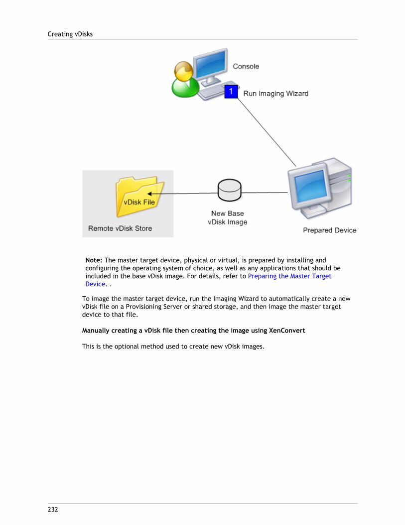
Note: The master target device, physical or virtual, is prepared by installing andconfiguring the operating system of choice, as well as any applications that should beincluded in the base vDisk image. For details, refer to Preparing the Master TargetDevice. .
To image the master target device, run the Imaging Wizard to automatically create a newvDisk file on a Provisioning Server or shared storage, and then image the master targetdevice to that file.
Manually creating a vDisk file then creating the image using XenConvert
This is the optional method used to create new vDisk images.
Creating vDisks
232
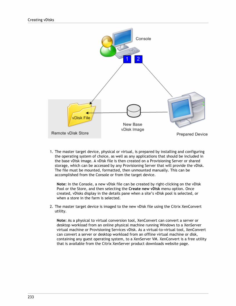
1. The master target device, physical or virtual, is prepared by installing and configuringthe operating system of choice, as well as any applications that should be included inthe base vDisk image. A vDisk file is then created on a Provisioning Server or sharedstorage, which can be accessed by any Provisioning Server that will provide the vDisk.The file must be mounted, formatted, then unmounted manually. This can beaccomplished from the Console or from the target device.
Note: In the Console, a new vDisk file can be created by right-clicking on the vDiskPool or the Store, and then selecting the Create new vDisk menu option. Oncecreated, vDisks display in the details pane when a site’s vDisk pool is selected, orwhen a store in the farm is selected.
2. The master target device is imaged to the new vDisk file using the Citrix XenConvertutility.
Note: As a physical to virtual conversion tool, XenConvert can convert a server ordesktop workload from an online physical machine running Windows to a XenServervirtual machine or Provisioning Services vDisk. As a virtual-to-virtual tool, XenConvertcan convert a server or desktop workload from an offline virtual machine or disk,containing any guest operating system, to a XenServer VM. XenConvert is a free utilitythat is available from the Citrix XenServer product downloads website page.
Creating vDisks
233

234
VHD Chain of Differencing Disks
Versioning simplifies vDisk update and management tasks, providing a more flexible androbust approach to managing vDisks.
A vDisk consists of a VHD base image file, any associated side-car files, and if applicable, achain of referenced VHD differencing disks. Differencing disks are created to capture thechanges made to the base disk image, leaving the original base disk unchanged. Eachdifferencing disk that is associated with a base disk represents a different version.
The following illustrates the file naming convention used and the relationship between a abase disk and all versions referencing that base disk.
VHD Chain
Note: vDisk versions are created and managed using thevDisk Versions dialog and byperforming vDisk versioning tasks.
Each time a vDisk is put into Maintenance Mode a new version of the VHD differencing diskis created and the file name is numerically incremented, as captured in the table thatfollows.

VHD Filename Properties Filename Lock File Filename
Base Image win7dev.vhd win7dev.pvp win7dev.lok
Version 1 win7dev.1.vhd win7dev.1.pvp win7dev.1.lok
Version 2 win7dev.2.vhd win7dev.2.pvp win7dev.2.lok
... ... ... ...
Version N win7dev.N.vhd win7dev.N.pvp win7dev.N.lokFor information on merging VHD files, refer to merging VHD files.
VHD Chain of Differencing Disks
235

236
Creating vDisks Automatically
A vDisk image can be created automatically using the Using the Imaging Wizard.

237
Using the Imaging Wizard to Create aNew vDisk
Use the Imaging Wizard to automatically create the base vDisk image from a master targetdevice.
Prerequisites
● Enable Windows Automount on Windows Server operating systems.
● Disable Windows Autoplay.
● Verify adequate free space exists in the vDisk store, which is approximately 101% ofused space on the source volumes.
● Make note of which NIC(s) the master target device was bound to when the ProvisioningServices software was installed on the target device. This information is necessaryduring the imaging process.
Note: If a Windows reboot request message displays before the imaging processcompletes, ignore the request until imaging completes successfully.
Imaging
The Imaging Wizard prompts for information that allows for connecting to the farm as wellas information necessary to set the appropriate credentials/Active Directory and licensinginformation to apply to this particular vDisk.
1. From the master target device's Windows Start menu, select Citrix>ProvisioningServices>Imaging Wizard. The wizard's Welcome page appears.
2. Click Next. The Connect to Farm page appears.
3. Enter the name or IP address of a Provisioning Server within the farm to connect to andthe port to use to make that connection.
4. Use the Windows credentials (default), or enter different credentials, then click Next.If using Active Directory, enter the appropriate password information.
5. On the Microsoft Volume Licensing page, select the volume license option to use fortarget devices or select None if volume licensing is not being used:
● None
● Key Management Service (KMS)
Note: Additional steps are required to implement KMS licensing after the vDiskimage is created. Refer to Managing Microsoft KMS Volume Licensing in theAdministrator's Guide for details.
● Multiple Activation Key (MAK)
Note: For information on managing MAK Licensing refer to Activating MicrosoftMAK Volume Licensing in the Administrator's Guide.
6. Select to create a new vDisk (default), or use an existing vDisk by entering that vDisksname, then click Next.
7. If the create new vDisk option was selected, the New vDisk dialog displays.
a. Enter a name for the vDisk
b. Select the Store where this vDisk will reside
c. Select the vDisk format from the appropriate drop-down menus. If the VHD formatis Dynamic, from the VHD block size drop-down, select the block size as either 2MB or 16 MB.
d. Click Next, then define volume sizes on the Configure Image Volumes page.8. Click Next The Add Target Device page appears.
9. Select the target device name, the MAC address associated with one of the NICs thatwas selected when the target device software was installed on the master targetdevice, and the collection to add this device to. Click Next. If the target device isalready a member of the farm, the Existing Target Devices page appears.
10. Click Next. Summary of Farm Changes appears.
11. Optional. Select to optimize the vDisk for use with Provisioning Services.
12. Verify all changes, then click Finish. A confirmation message displays.
13. Click Yes on the confirmation message to start the imaging process.
Using the Imaging Wizard to Create a New vDisk
238
239
Creating vDisk Files Manually
The following lists the major steps involved in creating and configuring the vDisk filemanually:
● Creating the vDisk File
● Formatting a Mounted vDisk
Creating a New vDisk File1. In the Console tree, right-click on the vDisk Pool in the site where you want to add
those vDisks, then select the Create vDisk menu option. The Create vDisk dialogappears.
2. If you accessed this dialog from the site’s vDisk pool, in the drop-down menu, select thestore where this vDisk should reside. If you accessed this dialog from the store, fromthe drop-down menu, select the site where this vDisk will be added.
3. In the Server used to create the vDisk drop-down menu, select the Provisioning Serverthat will create the vDisk.
4. Type a filename for the vDisk. Optionally, type a description for this new vDisk in thedescription textbox.
5. In the Size text box, scroll to select the appropriate size to allocate for this vDisk file.If the disk storing the vDisk images is formatted with NTFS, the limit is approximately 2terabytes. On FAT file systems, the limit is 4096 MB.
6. In the VHD Format text box, select the format as either Fixed or Dynamic (2040 GB forVHD emulating SCSI; 127 GB for VHD emulating IDE). If the VHD format is Dynamic, fromthe VHD block size drop-down, select the block size as either 2 MB or 16 MB.
7. Click Create vDisk, a progress dialog opens. Depending on the disk size and otherfactors, it may take several minutes or more to create the vDisk. After the vDisk issuccessfully created, it displays in the Console’s details pane and is ready to beformatted.
8. Right-click on the vDisk in the Console, then select Mount vDisk. The vDisk icon displayswith an orange arrow if mounted properly.
A vDisk image can not be assigned to, or boot from a target device until that target deviceexists in the Provisioning Services database. After creating the target device, in theConsole, select the Hard Disk boot option.
Formatting a vDiskIn order for a target device to access the new vDisk, after you have created and allocatedspace for the vDisk file on the Provisioning Server, you must format the vDisk.
Select from one of the following vDisk formatting methods:
● From the Console
● From the Target Device
Note: For information on configuring a vDisk for Microsoft Volume Licensing, refer toConfiguring Microsoft KMS Volume Licensing or Configuring Microsoft MAK VolumeLicensing.
To Format a Mounted vDisk From the Console
From the Provisioning Server, the vDisk should appear as a drive to the operating system.
Note: The disk used as the vDisk mounting point is always visible to the operating system,even when a vDisk has not been mounted. When Provisioning Services software isinstalled on the server, this drive is created. The drive letter will be the next availabledrive letter on your system. (For example, if your Provisioning Server has an A: drive, C:drive and D:).
When mounting a vDisk in Windows 2003 Enterprise or Windows 2008 Enterprise, the vDisk isnot assigned a drive letter. This is due to enhanced security in Windows, which does notacknowledge the new plugged-in disk until the user manually brings it online once
1. Open a Windows Explorer window (click My Computer on the Desktop or on the StartMenu).
2. Right-click on the vDisk, then select Format.
Note: Formatting erases all data stored on the vDisk. You should only format newvDisks that have not yet been imaged from the target device hard disk.
3. Create a descriptive name for the volume label for the vDisk.
4. Click Start, then click OK on the warning message that appears.
5. After formatting, close Windows Explorer.
6. Unmount the vDisk to make it available to target devices; in the Console, right-click onthe vDisk, then select the Unmount vDisk vDisk name option.
Creating vDisk Files Manually
240

Formatting a Mounted vDisk from the Target Device1. Ensure that the target device software is installed on the target device.
2. In the Console, create a new vDisk on the Provisioning Server. Assign this vDisk to theMaster Target Device.
3. From the Console, configure the target device to boot from its local hard disk, NOT tothe assigned vDisk.
4. PXE-Boot the target device. Once started, confirm connectivity from the target deviceto the Provisioning Server. When the connection is inactive the Target-Device statusicon in the system tray has a red X on it—if there is no red X, then the connection isgood.
5. Access the Disk Management utility in Windows by right-clicking My Computer on thedesktop and selecting Manage. The Computer Management window should appear.
6. Select Disk Management from the left window pane. The right window pane will displayall of the storage devices connected to the target device.
7. Identify the vDisk as the next available storage device after the boot disk (C:) and anyadditional physical drives connected to the computer. For example, if the target devicehas two physical drives, a primary boot disk labeled C:, and an additional storagedevice labeled D:, then the vDisk will be labeled E:.
8. Right-click the vDisk in the right window pane and select Format.
9. Type a Volume Label if desired, such as vDisk1.
10. Select the desired file system, such as NTFS. Leave the Allocation unit size to thedefault setting.
11. Select Perform a quick format. Leave the box labeled Enable file and foldercompression unchecked, then click OK.
12. Once the format is complete the disk should have a status of Healthy on the rightwindow pane. The disk is now formatted and ready to be imaged from the MasterTarget Device.
13. Unmount the vDisk to make it available to target devices; in the Console, right-click onthe vDisk, then select the Unmount vDisk vDisk name option.
Imaging the Master Target Device Using XenConvertAs a physical to virtual conversion tool, XenConvert can convert a server or desktopworkload from an online physical machine running Windows to a XenServer virtual machineor Provisioning Services vDisk. As a virtual-to-virtual tool, XenConvert can convert a serveror desktop workload from an offline virtual machine or disk, containing any guest operatingsystem, to a XenServer VM. XenConvert is a free utility that is available from the CitrixXenServer product downloads website page.
Note: The vDisk must be unmounted prior to creating the image.
Creating vDisk Files Manually
241

Creating vDisk Files Manually
242
243
Creating a Common vDisk Image forMultiple Target Platforms
The Common Image feature allows a single vDisk to simultaneously be supported bymultiple target device platforms, greatly reducing the number of vDisks an administratormust maintain. The procedure for creating a common image depends on the target deviceplatform.
Supported target device platforms include:
● A combination of XenServer VMs and physical devices (virtual-to-virtual andvirtual-to-physical). For details, refer to Creating Common Images for use with BothXenServer VMs and Physical Devices
● Multiple types of physical devices (different motherboards, network cards, video cardsand other hardware devices). For details, refer to Creating a Common Image for usewith Multiple Physical Device Types
244
Creating Common Images for use withBoth XenServer VMs and PhysicalDevices
XenServer Platinum Edition enables the provisioning of physical and virtual servers from thesame workload image.
The general procedures required to create this type of common image include:
1. Preparing a physical master target device used for creating the XenServer image.
2. Installing Provisioning Server Target Device software on a physical machine.
3. Installing XenConvert software on the physical machine, then converting it to a virtualmachine.
4. Installing XenServer Tools software.
5. Creating the XenServer vDisk image for use by both the physical and virtual machines.
Prerequistes:
● Appropriate XenServer Platinum Licensing
● Support for PXE on the local network
● DHCP must be installed and confgured on the local network.
Complete the detailed procedures that follow to create an image that is able to boot notonly on a physical machine but also within a XenServer virtual machine.
Prepare the Master Target Device
Install a supported Windows Operating System with the latest patches and device drivers ona physical machine. This physical machine will serve as the master target device .
Supported Operating Systems include:
● Windows Server 2003 (all editions)
● Windows XP (all editions)
● Windows Vista
● Business
● Enterprise
● Ultimate
Install the Provisioning Services Target Device Software
1. Log onto the master target device as a domain administrator, or a domain user (withlocal install privileges).
2. Install the Provisioning Server Target Device software on the physical machine.
3. Follow the onscreen prompts by selecting installation default settings.
4. When prompted, reboot the master target device.
Install XenConvert Software
XenConvert software and installation instructions can be downloaded from either theProvisioning Services product download site or the XenServer product download site.
After successfully installing XenConvert on the target device:
1. Run XenConvert on the target device to convert the physical machine into a XenServerVM.
2. Set the VM's vCPU setting to be the same as the physical system's vCPU setting.
Note: This very step is important for NT5 OS.
3. Change the XenServer VM MAC (it is using the Physical system's MAC address of the NIC),or remove the NIC and add a new NIC.
4. Boot the XenServer VM.
Install XenServer Tools
1. Log onto the master target device as a domain administrator, or a domain user (withlocal install privileges).
2. Run windows-pvdrivers-xensetup.exe , which can be downloaded from on the XenServerProduct installation CD or product download site. The Citrix XenServer Windows ToolsSetup warning dialog appears.
3. Click Yes to continue the install.
4. Follow the onscreen prompts and select the default settings. At the Choose InstallLocation dialog box, click Install.
5. When prompted by Windows Plug and Play dialogs, select the option to find driversautomatically.
6. When promoted select Yes for any unsigned driver dialog.
7. When promoted, Reboot master target device.
8. Run bindcfg from the Provisioning Services directory in order to verify that ProvisioningServices successfully binded to the XenServer NIC and the physical systems NIC.
Creating Common Images for use with Both XenServer VMs and Physical Devices
245
Image the Provisioning Server Master Target Device
Use either the Provisioning Services Imaging Wizard or XenConvert to create the XenServervDisk image.
After successfully creating the XenServer vDisk image, boot both the physical and virtualmachines in Standard Image mode.
For details on using the Provisioning Services Imaging Wizard, refer to Using the ImagingWizard. For details on using XenConvert to create the XenServer vDisk image, refer toXenConvert product documentation on the Provisioning Services or XenServer productdownload site.
Creating Common Images for use with Both XenServer VMs and Physical Devices
246
247
Creating a Common Image for use withMultiple Physical Device Types
The Common Image feature allows a single vDisk to simultaneously support differentmotherboards, network cards, video cards and other hardware devices. The result is a vDiskcapable of being used by heterogeneous target devices, greatly reducing the number ofvDisks an administrator must maintain.
Prerequisites● Make sure all target devices that will use the common image have the a consistent HAL
-- that is, they must have the same number of logical processors.
Note: A single processor hyper-threading capable system is considered to have twological processors when the hyper-threading is enabled in the BIOS.
● The BIOS structure, which is presented to the OS during the boot process, must be ofthe same format for all target devices that share a Standard Image. The BIOS Structurecontains a list of all the components connected to the motherboard so that theappropriate drivers are loaded to allow the components to function properly.
● Have either a 3Com Managed PC Boot Agent (MBA) or a PXE-compliant NIC available.This card is the common NIC that is inserted into each target device during the CommonImage build process.
● Install all the latest device drivers on each target device.
● Device drivers are missing if devices do not respond after you configure the commonimage. For example, if a target device’s USB mouse and keyboard do not respond afteryou assign the common image to the target device, it is likely that you have notinstalled drivers for that target device’s chipset. Go to device manager and check toinsure no yellow exclamation mark display on any devices, especially USB Root HUBsand controllers.
● Determine which target device contains the latest motherboard chipset. This targetdevice is used as the first target device in the common image build process. The latestIntel chipset driver always contains all the drivers for the previous chipset, therefore itis not necessary to install as many drivers when you build the common image.
● Except on the first target device, disable built-in NICs on all target devices that will usethe common image (leave the built-in NIC on the first target device enabled). Thisprevents confusion about which NIC to use during the common image building process
● Install Provisioning Services components
Building the Common ImageThe steps for building a common image are presented in several short procedures:
● Configuring the Master Target Device
● Exporting Specific Data Files
● Booting the Master Target Device
● Adding Additional Target Devices to the Common Image
Note: Important! When building the common image, create a vDisk that has enough spaceto accommodate additional information that is added by the common image buildprocess.
Configuring the Master Target Device1. Insert the common NIC into the Master Target Device.
2. Install the target device software on the Master Target Device. Select both the commonNIC and built-in NICs during the installation process.
3. Create a vDisk, then mount, format, and unmount it. You must create a vDisk that hasenough space to accommodate additional information added by the common imagebuild process.
4. Run the Imaging Wizard on the target device to build the vDisk.
5. (Recommended) Make a copy of the original vDisk created in Step 3 and save it in thevDisk directory on the Provisioning Server.
6. On the first target device, copy CIM.exe from C:\Program Files\Citrix\ProvisioningServices to a removable storage device, such as a USB flash drive. This utility is used toinclude disparate target devices in the common image.
7. Shut down the Master Target Device and remove the common NIC.
Exporting Specific Data Files1. Insert the common NIC into a target device that will be added to the common image,
then boot the target device from its local hard drive.
Note: Although the Windows OS must be installed on this target device, the targetdevice software does not have to be installed.
2. Copy CIM.exe from the removable storage device to this target device.
Creating a Common Image for use with Multiple Physical Device Types
248
3. At a command prompt, navigate to the directory in where CIM.exe is located, then runthe following command to extract the information form the target device into the .datfile:
CIM.exe e targetdeviceName.dat
where targetdeviceName identifies the first target device that will use the commonimage. For example, TargetDevice1.dat.
Copy the .dat file created in Step 3 to the removable storage device.
4. Shut down the target device and remove the common NIC.
To include additional target devices with disparate hardware in the common image, repeatStep1 through Step 6 for each device, giving each .dat file a unique name.
Booting the Master Target Device1. Reinsert the common NIC into the Master Target Device. Insert the NIC into the same
slot from which it was removed during the Configuring the Master Target Deviceprocedure. Before booting the Master Target Device, enter the BIOS setup and verifythat the common NIC is the NIC used in the boot process.
2. Using the common NIC, boot the Master Target Device from the vDisk, in Private Imagemode.
3. Copy CIM.exe and the .dat file associated with the first target device from theremovable storage device to the Master Target Device.
4. At a command prompt, navigate to the directory where the CIM.exe and the .dat fileare located.
5. Run the following command to merge the information from the .dat file into thecommon image:
CIM.exe m targetdeviceName.dat
6. Shut down the Master Target Device.
Adding Additional Target Devices to the CommonImage
1. Insert the common NIC into additional target devices that will be included in theCommon Image. Insert the NIC into the same slot from which it was removed in theExporting Specific Data Files procedure.
2. Using the common NIC, boot the target device off the vDisk in Private Image mode.
Creating a Common Image for use with Multiple Physical Device Types
249

3. Allow Windows time to discover and configure all the device drivers on the targetdevice (this will take some time). If prompted by the “Found New Hardware Wizard” toinstall new hardware, Cancel out of the wizard and proceed to Step 4.
Note: If Windows can’t install drivers for the built-in NIC on a target device, and thedrivers can not be installed manually, the common NIC and the target device’sbuilt-NIC are very similar to each other and the driver installation program tries toupdate the driver for both NICs. For example, this happens if the common NIC is anIntel Pro 100/s and the target device’s built-in NIC is an Intel Pro 100+. To resolvethis conflict, open System Properties. On the Hardware tab, click the DeviceManager button. In the Device Manager list, right-click the built-in NIC and clickUpdate Driver to start the Hardware Update Wizard. Choose Install from a list orspecific location and specify the location of the NIC's driver files.
4. Open Network Connections, right-click the connection for the built-in NIC and clickProperties in the menu that appears. (The icon for the built-in NIC is marked with a redX.)
5. Under This connection uses the following items, select Network Stack and click OK.
6. From a command prompt, run the following command:
C:\Program Files\Citrix\Provisioning Server\regmodify.exe
Note: After completing Steps 4-6, reboot the target device and allow Windows todiscover and configure any remaining devices. If prompted by the “Found NewHardware Wizard” to install new hardware, proceed through the Wizard to completethe hardware installation.
7. Using the original vDisk, repeat Step1 through Step 6 for each of the additional targetdevices to be included in the Common Image.
8. Once target devices have been included in the Common Image, on the Console, set thedisk access mode for the Common Image vDisk to Standard Image mode, then boot thedevices.
Creating a Common Image for use with Multiple Physical Device Types
250
251
Deploying vDisks
This section provides the information necessary to deploy new vDisks within a ProvisioningServices farm.
After a vDisk image is created, it is configured for deployment. vDisk deployment tasksinclude:
● Configuring the vDisk (for details refer to Configuring vDisks for Deployment)
● Assigning one or more target device(s) to the vDisk (for details, refer to AssigningvDisks to Target Devices
● Booting a target device (for details, refer to Booting target devices in the ManagingTarget Devices section)
252
Configuring vDisks for Deployment
vDisks are configured prior to being deployed. Configuration tasks include:
● Selecting the vDisk Access Mode (for details, refer to Selecting a vDisk Access Mode) andif applicable, the Write Cache Mode for that vDisk.
● Configuring the vDisk for Microsoft Volume Licensing (for details, refer to Configuring avDisk for Microsoft Volume Licensing).
● Enabling Active Directory machine account password management, if applicable (fordetails, refer to Enabling Domain Management.)
● Enabling printer management (for details, refer to Managing Printers).
● Additional Settings
● Enabling or disabling the streaming of this vDisk to assigned target devices (fordetails, refer to vDisk Properties) dialog).
● Providing vDisk identification information (for details, refer to Identificationinformation in the vDisk Properties dialog).
253
Selecting a vDisk Access Mode
The vDisk access mode options include:
● Standard Image Mode
● Private Image Mode
Standard Image ModeStandard Image mode allows multiple target devices to stream from a single vDisk image atthe same time; reducing the amount of vDisk management and reducing storagerequirements.
When a vDisk is configured to use Standard Image mode, it is set to read-only mode. Eachtarget device then builds a write cache to store any writes the operating system needs tomake. There are several write-cache options available. Because the vDisk is read-only, eachtime a target device boots, it always boots from a ‘clean’ vDisk. If a machine becomesinfected with a virus or spyware, the target device only needs to reboot the image.
When updates are made to a vDisk in Standard Image mode, changes against the base vDiskimage are captured in a differencing disk file (.aVHD), resulting in a new version of the baseimage. Each new version remains directly associated with the base image. Versioning allowsfor the updates captured in the differencing disk to be staged (Maintenance, Test,Production) before those changes become available to Production devices. If issues areencountered with a version, that version can simply be reverted. For details on versioning,refer to Updating vDisks.
While each target device is using the same vDisk, Provisioning Services personalizes thestreamed image for each target device, providing the information needed to ensure thedevice is uniquely identifiable on the network. In addition, the product provides amechanism to specify additional personality settings for each device. This feature allowsyou to store application specific values in the database and retrieve the target device’sunique value as the device loads. For more details, refer to Managing Target DevicePersonality.
Private Image ModeA vDisk that is in Private image mode closely models how a computer uses a regular harddrive. That is, only one target device can use a Private Image vDisk at a time.
The following illustrates Private Image vDisks (read/write) that are each assigned to asingle Production device, and a Standard Image vDisk (read-only) that is assigned to andshared by a collection of Production devices. For Standard Image vDisks, write cacheoptions include cache on server disk, on a devices hard disk drive, or in the devices RAM.
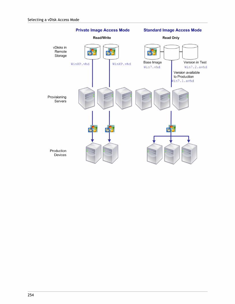
Selecting a vDisk Access Mode
254
255
Configuring the vDisk Access Mode
Use the Console to select from the following vDisk access modes:
● Private Image – Select this mode if a vDisk is only used by a single target device(read/write access is enabled).
● Standard Image – Select this mode if a vDisk is shared by multiple target devices(write-cache options enabled).
To configure the vDisk mode and any applicable write cache destination:
Note: Only those write cache destinations that are supported for Standard access modeappear enabled.
1. On the Console, right-click on the vDisk for which you want to configure the vDiskaccess mode, then select vDisk Properties. The vDisk Properties dialog appears.
2. Click on the General tab, then select the image mode (Standard or Private) that appliesto this vDisk from the Access Mode drop-down list.
3. If Standard image was selected, from the cache destination drop-down list, select theappropriate write cache destination. (Refer to the section that follows for write-cachedestination descriptions.)
4. Click OK to exit the vDisk Properties dialog.

256
Selecting the Write Cache Destination forStandard vDisk Images
Provisioning Services supports several write cache destination options. The write cachedestination for a vDisk is selected on the General tab, which is available from the vDisk FileProperties dialog.
Note: If the cache on local hard-drive type is selected, ensure that the hard-disk drive isformatted with NTFS for Windows devices with a minimum of 500 MB. If the cache on thetarget device RAM and Standard Image mode are selected, the max size of the RAM writecache is determined by the registry setting WcMaxRamCacheMB in the BNIStackParameters. This is a DWORD parameter. If the registry entry does not exist, then thedefault value used is 3584 MB.
The following lists valid write cache destinations:
● Cache on device hard drive
● Cache on device hard drive persisted (experimental phase only)
● Cache in device RAM
● Cache on a server disk
● Cache on server persisted
Cache on Device Hard DriveWrite cache can exist as a file in NTFS format, located on the target-device’s hard drive.This write cache option frees up the Provisioning Server since it does not have to processwrite requests and does not have the finite limitation of RAM.
The hard drive does not require any additional software to enable this feature.
Note: The write cache file is temporary unless the vDisk mode is set to Difference DiskImage mode.
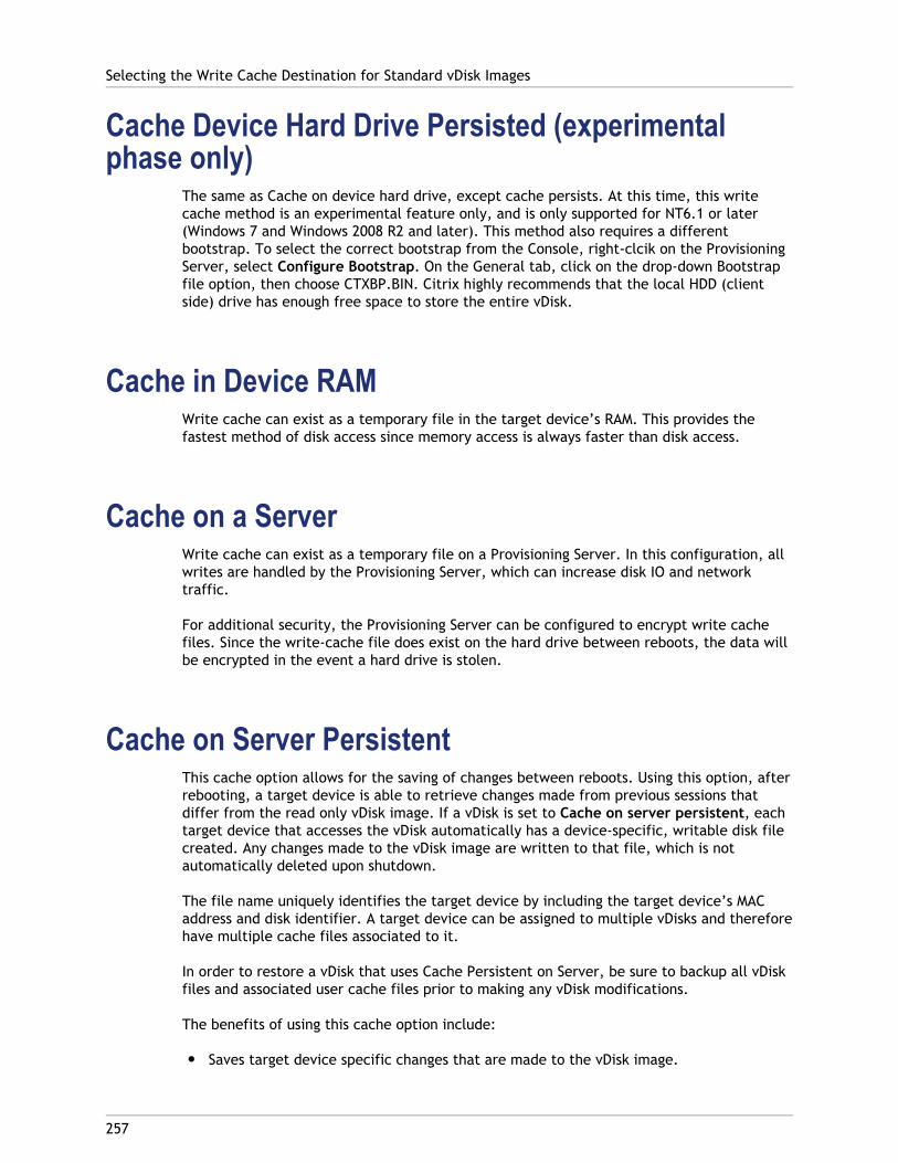
Cache Device Hard Drive Persisted (experimentalphase only)
The same as Cache on device hard drive, except cache persists. At this time, this writecache method is an experimental feature only, and is only supported for NT6.1 or later(Windows 7 and Windows 2008 R2 and later). This method also requires a differentbootstrap. To select the correct bootstrap from the Console, right-clcik on the ProvisioningServer, select Configure Bootstrap. On the General tab, click on the drop-down Bootstrapfile option, then choose CTXBP.BIN. Citrix highly recommends that the local HDD (clientside) drive has enough free space to store the entire vDisk.
Cache in Device RAMWrite cache can exist as a temporary file in the target device’s RAM. This provides thefastest method of disk access since memory access is always faster than disk access.
Cache on a ServerWrite cache can exist as a temporary file on a Provisioning Server. In this configuration, allwrites are handled by the Provisioning Server, which can increase disk IO and networktraffic.
For additional security, the Provisioning Server can be configured to encrypt write cachefiles. Since the write-cache file does exist on the hard drive between reboots, the data willbe encrypted in the event a hard drive is stolen.
Cache on Server PersistentThis cache option allows for the saving of changes between reboots. Using this option, afterrebooting, a target device is able to retrieve changes made from previous sessions thatdiffer from the read only vDisk image. If a vDisk is set to Cache on server persistent, eachtarget device that accesses the vDisk automatically has a device-specific, writable disk filecreated. Any changes made to the vDisk image are written to that file, which is notautomatically deleted upon shutdown.
The file name uniquely identifies the target device by including the target device’s MACaddress and disk identifier. A target device can be assigned to multiple vDisks and thereforehave multiple cache files associated to it.
In order to restore a vDisk that uses Cache Persistent on Server, be sure to backup all vDiskfiles and associated user cache files prior to making any vDisk modifications.
The benefits of using this cache option include:
● Saves target device specific changes that are made to the vDisk image.
Selecting the Write Cache Destination for Standard vDisk Images
257

● Same benefits as Standard Image Mode.
The drawbacks of using this cache option include:
● The cache file is available so long as the file remains valid. Any changes made to thevDisk force the cache file to be marked invalid. For example, if the vDisk is set toPrivate Image Mode, all associated cache files are marked invalid.
Note: Cache files that are marked as invalid are not deleted. Periodically, these filesshould be manually deleted.
Invalidating changes include:
● Placing a vDisk in Maintenance
● vDisk is placed in Private Image mode
● Mapping the drive from the Console
● Changing the location of the write cache file
● Using Automatic update
Selecting the Write Cache Destination for Standard vDisk Images
258
259
Configuring for Microsoft VolumeLicensing
Provisioning Services supports Microsoft Key Management Service (KMS) or MultipleActivation Key (MAK) volume licensing. This section provides details on configuring vDisksfor volume licensing.

260
Configuring Microsoft KMS VolumeLicensing
Microsoft provides two mechanisms for administering volume licenses. This sectiondescribes use of the Key Management Server (KMS) license keys with Provisioning Services toapply volume licenses for Microsoft Server 2008, Windows 7 and Vista, as well as Office2010.
Note: To support KMS licensing, the Soap Server user account must have the 'Performvolume maintenance tasks' (SeManageVolumePrivilege) privilege.
KMS volume licensing utilizes a centralized activation server that runs in the datacenter,and serves as a local activation point (opposed to having each system activate withMicrosoft over the internet).
Note: When preparing or updating a KMS configured vDisk that will be copied or cloned, itis important to complete the final KMS configuration task, which is to change the vDiskmode from Private Image Mode to Shared Image Mode, before copying or cloning thevDisk to other Provisioning Servers. Also, both the .pvp and .vhd file must be copied toretain the properties and KMS configuration of the original vDisk.
The tasks involved in configuring a vDisk image to use KMS volume licensing and managingthat vDisk in a Provisioning Services farm include:
● Enabling KMS licensing on the vDisk being created. This is accomplished by selecting theKMS menu option on the Microsoft Volume Licensing tab when running the ImagingWizard (refer to Imaging Wizard for details).
● Preparing the new base vDisk image
● Maintaining or upgrading the vDisk image
Note: If KMS licensing was not configured on the vDisk when the Imaging Wizard was run,it can alternatively be configured using the Console user interface (refer to the MicrosoftVolume Licensing tab, or the MCLI and PowerShell command-line interfaces (refer to theMCLI or PowerShell Programmers Guide for details).
Preparing the New Base vDisk Image for KMS VolumeLicensing
After a vDisk is created using the Imaging Wizard, it must be reset to a non-activated stateusing the rearm command.
It is important to perform this operation on a system booted from the vDisk in Private ImageMode so that the master target device hard disk's rearm count is not reduced.
Note: Microsoft limits the number of times you can run rearm on an installed OS image.The operating system will need to be reinstalled if the number of allowed rearm attemptsis exceeded.
1. Boot the target device from the vDisk in Private Image Mode to rearm.
● For Windows Vista, 7, 2008, and 2008R2 run: cscript.exe slmgr.vbs -rearm
● For Office 2010 (for 64bit client): Program Files(x86)\Common Files\microsoftshared\OfficeSoftwareProtectionPlatform\OSPPREARM.EXE
● For Office 2010 (for 32bit client): Program Files(x32)\Common Files\microsoftshared\OfficeSoftwareProtectionPlatform\OSPPREARM.EXE
2. A message will prompted you to reboot the system, DO NOT REBOOT. Instead shut downthe Target device.
3. Set the vDisk mode to Standard Image mode.
4. Stream the vDisk to one or more target devices.
Maintaining or Upgrading a vDisk Image that UsesKMS Volume Licensing
To maintain or upgrade a vDisk image that is configured to use KMS volume licensing:
1. Set the vDisk mode to Private Image mode.
2. Stream the vDisk to a target device.
3. Apply the OS/application service pack/update, then shutdown the target device.
4. Set the vDisk mode back to Shared Image mode.
5. Stream the vDisk to the target device in Shared Image mode.
Note: If Office 2010 is installed as vDisk update, or after vDisk has gone through basedisk preparation once, then the base disk preparation needs to be repeated asfollows:
a. In the Console, right-click on the vDisk, then select the File Properties menuoption. The vDisk File Properties dialog appears.
b. Click on the Microsoft Volume Licensing tab, then change the licensing option fromKMS to None.
c. On the Mode tab, set the vDisk access mode to Private Image mode.
d. PXE boot to the vDisk in Private Image mode to rearm:
● For Windows Vista, 7, 2008, and 2008R2 run: cscript.exe slmgr.vbs -rearm
Configuring Microsoft KMS Volume Licensing
261

● For Office 2010 (for 64bit client): Program Files(x86)\Common Files\microsoftshared\OfficeSoftwareProtectionPlatform\OSPPREARM.EXE
● For Office 2010 (for 32bit client): Program Files(x32)\Common Files\microsoftshared\OfficeSoftwareProtectionPlatform\OSPPREARM.EXE
e. A message will prompted you to reboot the system, DO NOT REBOOT. Instead shutdown the Target device.
f. In the Console, right-click on the vDisk, then select the File Properties menuoption. The vDisk Properties dialog appears.
g. Click on the Microsoft Volume Licensing tab, then change the license option fromNone to KMS.
h. On the Mode tab, set the vDisk access mode to Shared Image mode.
i. Stream the vDisk to the target devices.
Configuring Microsoft KMS Volume Licensing
262

263
Configuring Microsoft MAK VolumeLicensing
Microsoft provides two mechanisms for administering volume licenses. This sectiondescribes the use of Multiple Activation Keys (MAKs). A MAK corresponds to a certainnumber of purchased OS licenses. The MAK is entered during the installation of the OS oneach system, which activates the OS and decrements the count of purchased licensescentrally with Microsoft. Alternatively, a process of 'proxy activation' is done using theVolume Activation Management Toolkit (VAMT). This allows activation of systems that donot have network access to the internet. Provisioning Services leverages this proxyactivation mechanism for Standard Image mode vDisks that have MAK licensing modeselected when the vDisk is created.
Note: In order for MAK licensing to work, the Volume Activation Management Tool (VAMT)must be installed on all Provisioning Servers within a farm. This tool is available fromhttp://www.microsoft.com/downloads/en/details.aspx?FamilyID=ec7156d2-2864-49ee-bfcb-777b898ad582&displaylang=en.
MAK licensing tasks include:
● Setting the vDisk's licensing mode
● Entering MAK User Credentials
● Activating target devices that use MAK enabled vDisks
● Maintaining MAK Activations
Setting the vDisk's licensing mode
A vDisk can be configured to use Microsoft Multiple Activation Key (MAK) licensing when theImaging Wizard is run (refer to Imaging Wizard). If MAK licensing was not configured whenthe Imaging Wizard was run, the vDisk's licensing mode property can be set using theConsole, MCLI, or PowerShell user interface. The licensing mode should be set beforeattempting to activate target devices.
Note: For information on using the command-line interfaces, refer to the MCLI orPowerShell Programmers Guide.
Entering MAK User Credentials
Before target devices that use MAK enabled vDisks can be activated, MAK user credentialsmust be entered for a site.
Note: The user must have administrator rights on all target devices that use MAK enabledvDisks and on all Provisioning Servers that will stream the vDisks to target devices.
To enter credentials:

1. Right-click on the site where the target devices exist, then select the Properties menuoption.
2. On the MAK tab, enter the user and password information in the appropriate text boxes,then click OK.
Activating target devices that use MAK enabled vDisks
After a vDisk is configured for MAK volume licensing and user credentials have beenentered, each booted target device that uses the vDisk needs to be activated with a MAK.
Note: After all licenses for a given MAK have been used, a new key will be required inorder to allow additional target devices that share this vDisk image to be activated.
To activate target devices that use MAK volume licensing from the Console:
1. Boot all target devices that are to be activated.
2. In the Console, right-click on the collection or view that includes target devices thatrequire MAK license activation, then select the Manage MAK Activations... menuoption. The Manage MAK Activations dialog appears.
3. In the Multiple activation key text box, enter the MAK to be used to activate the targetdevices.
4. The number of booted target devices that require activation, display on the dialog.From the list of booted devices, check the box next to each target device that shouldbe activated.
5. Click OK to activate licensing for all selected target devices (do not close the dialoguntil the activation process is completed. The process can be stopped by clicking theCancel button. Closing the dialog before the activation process completes stops theprocess and may result in some target devices not being activated). The Status columnindicates if a target device is currently being activated (Activating) or the activationfailed (Failed). If all target devices were activated successfully, click OK to close thedialog. After the activation process completes, if one or more target devices were notselected to be activated, or if devices were not activated successfully, the dialogdisplays listing any unactivated devices. After resolving any issues, repeat this step toactivate the remaining target devices.
Note: The Manage MAK Activations... option does not display after all currentlybooted target devices have been successfully activated.
Maintaining MAK Activations
When a target device has a MAK activated vDisk assigned, unassigning it removes anysaved MAK reactivation information. If the vDisk is reassigned in the future, the targetdevice will not reactivate. To prevent the loss of MAK activation, do not unassign theactivated disk from the target device.
To change a target device's vDisk, without losing the MAK activation, select one of thefollowing methods:
a. Assign more than one vDisk to the target device and set the default accordingly.
Configuring Microsoft MAK Volume Licensing
264

b. Assign additional vDisks to the target device and temporarily disable the MAKactivated vDisk.
To update a MAK activated vDisk, the AutoUpdate feature must be used so that the MAKactivation information, required for shared device reactivation, is maintained.
Additional MAK considerations:
● Use of manual vDisk updates (unassigning one vDisk and reassigning another vDisk)will result in the loss of the required MAK activation information and will require anew activation, which would consume another license.
● Use of AutoUpdate to deploy a new vDisk, from a different OS install than theprevious vDisk, will result in mismatched MAK activation information. In this case, anew activation must be performed from the command line interface, as onlyunactivated target devices can be activated from the MMC console.
Configuring Microsoft MAK Volume Licensing
265
266
Configuring a vDisk for Microsoft VolumeLicensing
A vDisk can be configured for Microsoft Key Management Service (KMS) or MultipleActivation Key (MAK) volume licensing when the Imaging Wizard is run. If it was notconfigured when the Imaging Wizard was run, it can still be configure from the Console:
Note: The MCLI and SoapServer command-line interfaces can also be used to configureMicrosoft volume licensing.
1. Select the vDisk in the Console, then right-click and select File Properties. The vDiskFile Properties dialog appears.
2. Click the Microsoft Volume Licensing tab, then select the MAK or KMS licensing method.
3. Click OK. After a vDisk has been configured for Microsoft volume licensing, additionalsteps may be necessary to activate or maintain that vDisk. For additional information,refer to Managing Microsoft MAK Licensing on Target Devices. and Configuring MicrosoftKMS Volume Licensing.

267
Configuring vDisks for Active DirectoryManagement
Integrating Provisioning Services and Active Directory allows administrators to:
● Select the Active Directory Organizational Unit (OU) in which Provisioning Servicesshould create a target device computer account.
● Take advantage of Active Directory management features, such as delegation of controland group policies.
● Configure the Provisioning Server to automatically manage the computer accountpasswords of target devices.
Note: For more information about using Active Directory organizational units anddelegation of control, refer to Microsoft Active Directory documentation.
The following major tasks are used to manage Active Directory in a Provisioning Servicesenvironment:
● Managing Domain Passwords
● Enabling Domain Management
● Managing Domain Computer Accounts

268
Active Directory Integration Prerequistes
Before integrating Active Directory within the farm, verify that the following prerequistesare met:
● The Master Target Device was added to the domain before building the vDisk.
● The Disable Machine Account Password Changes option was selected when the imageoptimization wizard was run during imaging.
After all prerequisites have been verified, new target devices can be added and assigned tothe vDisk. A machine account must then be created for each target device.

269
Managing Domain Passwords
When target devices access their own vDisk in Private Image mode, there are no specialrequirements for managing domain passwords. However, when a target device accesses avDisk in Standard Image mode, the Provisioning Server assigns the target device its name. Ifthe target device is a domain member, the name and password assigned by ProvisioningServer must match the information in the corresponding computer account within thedomain. Otherwise, the target device is not able to log on successfully. For this reason, theProvisioning Server must manage the domain passwords for target devices that share avDisk.
To enable domain password management you must disable the Active Directory-(or NT 4.0Domain) controlled automatic re-negotiation of machine passwords. This is done byenabling the Disable machine account password changes security policy at either thedomain or target-device level. Provisioning Server provides equivalent functionality throughits own Automatic Password Renegotiate feature.
While target devices booting from vDisks no longer require Active Directory passwordrenegotiation, configuring a policy to disable password changes at the domain level appliesto any domain members booting from local hard drives. This may not be desirable. A betteroption is to disable machine account password changes at the local level. This can beaccomplished by selecting the Optimize option when building a vDisk image. The settingwill then be applied to any target devices that boot from the shared vDisk image.
Note: The Provisioning Server DOES NOT in any way change or extend the ActiveDirectory schema. Provisioning Server’s function is to create or modify computeraccounts in Active Directory, and reset passwords.
When domain password management is enabled, it:
● Sets a unique password for a target device.
● Stores that password in the respective domain computer account.
● Gives the information necessary to reset the password at the target device before itlogs on to the domain.
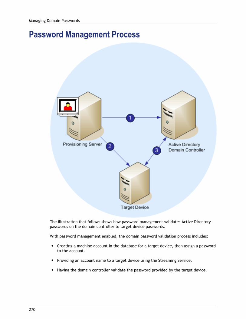
Password Management Process
The illustration that follows shows how password management validates Active Directorypasswords on the domain controller to target device passwords.
With password management enabled, the domain password validation process includes:
● Creating a machine account in the database for a target device, then assign a passwordto the account.
● Providing an account name to a target device using the Streaming Service.
● Having the domain controller validate the password provided by the target device.
Managing Domain Passwords
270
271
Enabling Domain Management
Each target device that logs on to a domain requires a computer account on the domaincontroller. This computer account has a password that is maintained by the Windowsdesktop OS and is transparent to the user. The password for the account is stored both onthe domain controller and on the target device. If the passwords stored on the targetdevice and on the domain controller do not match, the user can not log on to the domainfrom the target device.
Domain management is activated by completing the following tasks:
● Enabling Machine Account Password Management
● Enabling Automatic Password Management
Enabling Machine Account Password ManagementTo enable machine account password management, complete the following:
1. Right-click on a vDisk in the Console, then select the File Properties menu option.
2. On the Options tab, select Active Directory machine account password management.
3. Click OK, then close the properties dialogs, then restart the Streaming Service.
Enabling Automatic Password ManagementIf your target devices both belong to an Active Directory domain and are sharing a vDisk,the following additional steps must be completed:
To enable automatic password support, complete the following:
1. Right-click on a Provisioning Server in the Console, then select the Properties menuoption.
2. Select the Enable automatic password support option on the Options tab.
3. Set the number of days between password changes.
4. Click OK to close the Server Properties dialog.
5. Restart the Streaming Service.
272
Managing Domain Computer Accounts
The following tasks are normally performed in the Active Directory Users and ComputersManagement Console. However, these actions must now be performed using theProvisioning Server in order to take full advantage of product features.
● Supporting Cross-Forest Scenarios
● Giving Access to Users from Another Domain Provisioning Services AdministratorPrivileges
● Adding Target Devices to a Domain
● Removing Target Devices From a Domain
● Reset Computer Accounts
Supporting Cross-Forest ScenariosTo support cross-forest scenarios:
● Ensure that DNS is properly set up. (Refer to Microsoft's web site for information on howto prepare DNS for a Forest Trust.)
● Raise the forest functional level of both forests to Windows Server 2003.
● Create the forest trust. In order for Provisioning Services and the user from theProvisioning Services domain to create an account in a domain from another forest,create an Inbound Trust from the external forest to the forest Provisioning Services isin.
Parent-child domain scenario
A common cross-domain configuration includes the Provisioning Server in a parent domainand users, from one or more child domains, want to administer Provisioning Services andmanage Active Directory accounts within their own domains.
To implement this configuration:
1.Create a Security Group in the child domain. (It can be a Universal, Global, or LocalDomain Group). Make a user from the child domain a member of this group.
2.From the Provisioning Server Console, in the parent domain, make the child domainsecurity group a Provisioning Services Administrator.
3. If the child domain user does not have Active Directory privileges, use the Delegation Wizard in the Active Directory Users & Computers Management Console to assign,

create, and delete a user's computer account rights for the specified OU.
4. Install the Provisioning Services Console in the child domain. No configuration isnecessary. Log into the Provisioning Server as the child domain user.
Cross-forest configuration
This configuration is similar to the cross-domain scenario, except that the ProvisioningServices Console, user, and Provisioning Services administrator group are in a domain that isin a separate forest. The steps are the same as for the parent-child scenario, except that aforest trust must first be established.
Note: Microsoft recommends that administrators do not delegate rights to the defaultComputers container. The best practice is to create new accounts in the OUs.
Giving Access to Users from Another DomainProvisioning Services Administrator Privileges
There are several methods for giving Provisioning Services Administrator privileges to usersthat belong to a different domain. However, the following method is recommended:
1. Add the user to a Universal Group in their own domain (not the Provisioning ServicesDomain).
2. Add that Universal Group to a Local Domain Group in the PVS domain.
3. Make that Local Domain Group the PVS Admin group.
Adding Target Devices to a DomainTo add target devices to a domain:
Note: The machine name used for the vDisk image is to never be used within yourenvironment again.
1. Right-click on one or more target devices in the Console window (alternatively,right-click on the device collection itself to add all target devices in this collection to adomain). Select Active Directory, then select Create machine account. The ActiveDirectory Management dialog appears.
2. From the Domain scroll list, select the domain that the target device(s) belongs to, orin the Domain Controller text box, type the name of the domain controller that thetarget devices should be added to (if you leave the text box blank, the first DomainController found is used).
3. From the Organization unit (OU) scroll list, select or type the organization unit to whichthe target device belongs (the syntax is ‘parent/child,’ lists are comma separated; ifnested, the parent goes first).
Managing Domain Computer Accounts
273

4. Click the Add devices button to add the selected target devices to the domain anddomain controller. A status message displays to indicate if each target device wasadded successfully. Click Close to exit the dialog.
Removing Target Devices From a DomainTo remove target devices from a domain:
1. Right-click on one or more target devices in the Console window (alternatively,right-click on the device collection itself to add all target devices in this collection to adomain). Select Active Directory Management, then select Delete machine account.The Active Directory Management dialog appears.
2. In the Target Device table, highlight those target devices that should be removed fromthe domain, then click the Delete Devices button. Click Close to exit the dialog.
Reset Computer AccountsTo reset computer accounts for target devices in an Active Directory domain:
1. Right-click on one or more target devices in the Console window (alternatively,right-click on the device collection itself to add all target devices in this collection to adomain), then select Active Directory Management, then select Reset machineaccount. The Active Directory Management dialog appears.
2. In the Target Device table, highlight those target devices that should be reset, thenclick the Reset devices button.
Note: This target device should have been added to your domain while preparing thefirst target device.
3. Click Close to exit the dialog.
4. Disable Windows Active Directory automatic password re-negotiation. To do this, onyour domain controller, enable the following group policy: Domain member:Disable machine account password changes.
Note: To make this security policy change, you must be logged on with sufficientpermissions to add and change computer accounts in Active Directory. You have theoption of disabling machine account password changes at the domain level or locallevel. If you disable machine account password changes at the domain level, thechange applies to all members of the domain. If you change it at the local level (bychanging the local security policy on a target device connected to the vDisk in PrivateImage mode), the change applies only to the target devices using that vDisk.
5. Boot each target device.
Managing Domain Computer Accounts
274
275
Managing Load Balancing Across Servers
A vDisk can be configured so that a single server provides that vDisk, or configured so thatmultiple servers can provide the vDisk using a load balancing algorithm.
To configure load balancing on a vDisk
1. Right-click on the vDisk in the Console, then select the Load Balancing... menu option.
2. Select to enable load balancing or to assign a single Provisioning Server to provide thisvDisk, then click OK. Refer to the table below for dialog details.
Note: For details on configuring for high availability, refer to Managing for HighlyAvailable Implementations.
The following table describes the vDisk Load Balancing dialog.
Field/Button Description
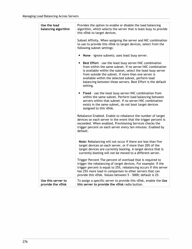
Use the loadbalancing algorithm
Provides the option to enable or disable the load balancingalgorithm, which selects the server that is least busy to providethis vDisk to target devices.
Subnet Affinity. When assigning the server and NIC combinationto use to provide this vDisk to target devices, select from thefollowing subnet settings:
● None – ignore subnets; uses least busy server.
● Best Effort – use the least busy server/NIC combinationfrom within the same subnet. If no server/NIC combinationis available within the subnet, select the least busy serverfrom outside the subnet. If more than one server isavailable within the selected subnet, perform loadbalancing between those servers. Best Effort is the defaultsetting.
● Fixed – use the least busy server/NIC combination fromwithin the same subnet. Perform load balancing betweenservers within that subnet. If no server/NIC combinationexists in the same subnet, do not boot target devicesassigned to this vDisk.
Rebalance Enabled. Enable to rebalance the number of targetdevices on each server in the event that the trigger percent isexceeded. When enabled, Provisioning Services checks thetrigger percent on each server every ten minutes. Enabled bydefault.
Note: Rebalancing will not occur if there are less than fivetarget devices on each server, or if more than 20% of thetarget devices are currently booting. A target device that iscurrently booting will not be moved to a different server.
Trigger Percent The percent of overload that is required totrigger the rebalancing of target devices. For example: If thetrigger percent is equal to 25%, rebalancing occurs if this serverhas 25% more load in comparison to other servers that canprovide this vDisk. Values between 5 - 5000; default is 25.
Use this server toprovide the vDisk
To assign a specific server to provide this vDisk, enable the Usethis server to provide the vDisk radio button.
Managing Load Balancing Across Servers
276
277
Managing Printers
Provisioning Server provides a Printer Management feature that allows you to manage whichprinters target devices have access to on a vDisk. Printers are managed from the TargetDevice Properties dialog.
This feature should not be enabled if you use Active Directory to manage printers. If youuse an existing printer management tool, this feature should be disabled to avoid printersetting conflicts.
Printers can only be added to the top-level differencing disk version while it is underMaintenance or if it is a Private Image. If a device boots from a previous version, the printerconfiguration may not match.
There are two types of printers that can appear in the Console window:
● Network Printers
● Local Printers
Before a target device can access a printer, the following tasks must be completed in theorder that follows:
● Installing Printers on the vDisk
● Enabling Printers on the vDisk
● Enabling the Printer Management Feature

278
Installing Printers on a vDisk
Printers must be installed on the vDisk image before the printers are available to targetdevices booting from that disk. Printers can only be added to the top-level differencing diskversion while it is under Maintenance or if it is a Private Image. If a device boots from aprevious version, the printer configuration may not match.
To install printers on the vDisk:
1. Change the vDisk image mode to Private Image mode.
2. Install the required printers on the target device that is using the vDisk.
3. Perform a clean shut-down of the target device that is using the vDisk.
4. If this vDisk is shared by users, change the vDisk image mode back to Shared Imagemode.
5. Verify that the printers display in the Console:
a. Right-click on the target device, select the Properties menu option.
b. Select the vDisks tab, then click on the Printers button. Printers associated withthat vDisk should appear in the list of available printers.
After successfully installing printers, the next step is to enable printers for target devicesthat access this vDisk (for details, refer to enable printers for target devices).
279
Enabling or Disabling Printers on a vDisk
Note: The Printer Management feature is only recommended if you are not using ActiveDirectory to manage printer groups.
By default, printers are not enabled on the vDisk. Enable or disable printers from theTarget Device Properties vDisk tab. On the Printers dialog, enable the checkbox next toeach printer to enable or disable it. After enabling (assigning) printers to target devices,the Printer Management feature must then be enabled on the vDisk.
Until Printer Management is enabled, all printers that are installed on the target device areavailable to that target device. By enabling Printer Management, you can select printers orremove printers from individual target devices.
After a target device boots, printer information, which is included in a vDisk image,becomes available to target devices. Printer Management is initially disabled until allprinter-to-target device assignments are completed for the vDisk. Disabling individualprinters prohibits target devices from accessing those printers.
Note: Disabling printers does not remove the printer information from the vDisk. Changesto the target devices printer assignments do not occur until the target device reboots.
Examples of reasons you may want to disable Printer Management include:
● You may be using a different printer system that installs the valid printers on eachtarget device and software may delete them or cause conflicting settings.
● Printers that are included on the vDisk should be accessible to all users.
● The system needs to be configured before being deployed. Until the PrinterManagement feature is enabled, changes can be made for different target devices asneeded.
All printers installed on a vDisk appear in the Details panel when the Printers group folder isexpanded for that vDisk.
If a disk is a HA vDisk (has a duplicate with same vDisk name), changes to that printer (if itis enabled or disabled for a target device) are automatically made to the duplicate vDisk.
Enablement Methods
Using the Console, you can manage which target devices use which printers. There areseveral methods for managing target device printer assignments. Choose from the followingmethods:
● Enabling printers for target devices using the Printer settings option. Use this method toenable or disable a single printer to multiple target devices accessing a vDisk.
● Enabling printers for target devices using the Printers group folder. Use this method toselect printer settings (enable/disable; default) for a single target device.
● Enabling printers using Copy and Paste. Use this method to copy printer settings of onetarget device (enabled/disabled; default printer), to one or more target devicesselected in the Details panel.
● Enabling printers using an existing target device as a template. Use this method toautomatically set printer settings when a target device is added to the network.
Note: The Administrator may choose to limit the number of printers for particular targetdevices or select different default printers for particular target devices. The settings thatare selected are saved to the target device’s personality information (if the limit for thisfield, 65K, is reached, a message appears indicating that some of the settings will not besaved and offers suggestions for decreasing the size).
Enabling or Disabling Printers on a vDisk
280
281
Methods for Enabling Printers on a vDisk
Choose from the following methods to enable printers on a vDisk:
● Enabling printers for target devices using the Printer Settings option
● Enabling printers for target devices using the Printers group folder
● Enabling printers using Copy and Paste
● Enabling printers using an existing target device as a template
Enabling printers for target devices using the PrinterSettings option
Use this method to assign a single printer to multiple target devices. This method is veryuseful when managing the printer-to-all target devices relationship.
1. In the Console tree, under Provisioning Servers, click the Printers group folder. Allprinters associated with that group appear in the Details panel.
2. Right-click on a printer in the Details panel, then select the Client Printer Settings...menu option. The printer settings dialog for that printer appears.
3. Enable or disable this printer for one or more target devices using any of the followingoptions:
● In the Enable column, select the checkbox next to each target device to enable ordisable use of this printer.
● Select the checkbox under the dialogs Enable heading to enable or disable thisprinter for all target devices assigned to the vDisk.
4. To select this printer as the default printer for target devices accessing this vDisk,select from the following methods:
● Select the Default checkbox in the dialogs Default heading to set this printer as thedefault for all target devices assigned to this vDisk.
● Highlight one or more target devices, then right-click to open the context menu.Select from the following menu options; Default, NotDefault All Default All NotDefault
● In the Default column, select the checkbox next to each target device that shoulduse this printer as the default printer. If there is only one printer, that printer isautomatically set as the default printer.
5. Click OK to save settings for this printer and exit the dialog.
Enabling printers for target devices using the Printersgroup folder
Use this method to select printer settings (enable/disable; default) for a single targetdevice.
Note: After selecting printer settings for a single target device, you may choose toduplicate this target devices printer settings using the Copy and Paste features.
1. Under the target device’s vDisk, click the Printers group folder in the tree. Printers thatare associated with that group appear in the Details panel. By default, printers are notenabled for a target device and the first printer listed is set as the default printer.
2. Select or deselect the Enable checkbox next to each printer to enable or disable theprinter for this target device. You can also choose from one of the additional selectionmethods that follow.
In the Details panel:
● Select or unselect the Enable checkbox within the table heading to enable ordisable all printers.
● Highlight a printer, then use the space bar to enable or disable printers.
Enabling printers using Copy and PasteUse this method to set the same printer settings (enabled/disabled; default printer) thatexist for one target device, to one or more target devices that use the same vDisks. Thismethod is particularly useful when adding new target devices and those target devices usethe same vDisks, and therefore the same printers, as an existing target device.
1. In the Console, right-click on the target device that you want to copy printer settingsfrom.
2. Select the Copy menu option. The Copy target device properties dialog appears.
3. Under Options, select Printers, then click OK to exit the dialog.
4. In the Tree, highlight the Target Devices directory so that all target devices appear inthe Details panel.
5. Highlight one or more target devices that you want to paste the printer settings to(enable/disable; default).
6. Right-click on the highlighted target devices, then select the Paste menu option.
Methods for Enabling Printers on a vDisk
282
Enabling printers using an existing target device as atemplate
Use this method if you want all new target devices, that are being added to your network,to automatically share printer settings (enable/disable; default).
1. In the Console, double-click the target device that you want to select as the template.The Target Device Properties dialog appears.
2. On the General tab, select the Set as default target device option.
3. Click OK to exit the dialog.
Methods for Enabling Printers on a vDisk
283

284
Enabling the Printer Management Feature
Note: The Printer Management feature is only recommended if you are not using ActiveDirectory.
After assigning printers to target devices, the Printer Management feature must be enabledbefore any printers on the target device can be removed. Until Printer Management isenabled, all printers installed on the target device are available to the target device. Oncethe feature is enabled, any changes to target devices printer settings (enable/disable;default) become available the next time the target device boots from the vDisk.
If the Printer Management feature is disabled and a target device boots from a vDisk thathas printers installed on it, that target device has access to all printers on that vDisk. If thePrinter Management feature is enabled and the target device boots from that same vDisk,that target device can only access those printers that are enabled for that target device.
To enable or disable printers on a selected vDisk:
1. In the Console, expand the Provisioning Server node in the tree panel, then select thevDisk that you want printers enabled or disabled on.
2. Select File Properties from the right-click menu, then select the Options tab.
3. Under Printer Settings, select the Enable the Printer Settings checkbox option toenable settings, or leave the checkbox blank to disable printer settings.
4. If the Enable the Printer Management checkbox is selected, the Enable PrinterManagement menu options appear checked when the Printers group is highlighted.
5. If the Enable the Printer Management checkbox appears disabled, all printers exist onthe selected vDisk.
You can also choose from the following methods to enable or disable the PrinterManagement feature using right-click menus:
Printers Group
In the Tree, under Provisioning Servers, expand a Provisioning Server, then expand the vDiskfor which you want to disable Printer Management. Right-click on the Printers folder forthat vDisk, then select the Disable Printer Management option.
Virtual Disk
In the Tree, under Provisioning Servers, right click on the vDisk for which you want todisable Printer Management, then select the Disable Printer Management option.
285
Support for Replicated vDisk Storage
Provisioning Services supports the replication of vDisks on stores that are local(local/attached storage on Provisioning Servers), as well as replication of vDisks acrossmultiple sites that use shared storage.
Replication considerations include:
● All Provisioning Servers must have network connectivity with all other servers in thefarm.
● Replication must be properly configured to work with Provisioning Services and meet allrequirements.
● Provisioning Services files to be replicated include: *.vhd, *.avhd, *.lok, and *.pvp. Ifimporting existing vDisks, the *.xml (manifest files) may also be replicated.
● It is not necessary to shut down a server during the replication process.
● Store path must be set for each Provisioning Server.
Note: If setting an override store path on the Server's Properties dialog, the pathmust be set prior to creating a new version of the vDisk. Because this pathinformation is stored and referenced in the .VHD header information, changing thepath after versioning may cause unexpected results.
● Necessary storage must be available and have read/write access.
Note: While DFS Replication can be used with Provisioning Services, DFS Namespaces arenot supported as store paths.
The illustrations that follow show both replication scenarios, each with a version that is notavailable to stores on all local servers, or a version that is not available across sharedstorage. In each case, Provisioning Services allows you to view the replication status fortroubleshooting purposes.
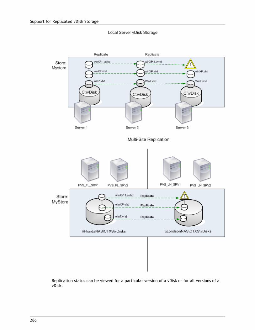
Replication status can be viewed for a particular version of a vDisk or for all versions of avDisk.
Support for Replicated vDisk Storage
286
Troubleshooting and Viewing Replication Status for aParticular vDisk
Provisioning Services allows users to view the availability of replicated vDisks toProvisioning Servers within a farm.
1. Right-click on a vDisk in the Console, then select the Versions... menu option. ThevDisk Versions dialog appears.
2. Highlight a version in the dialog, then click the Replication button. The vDisk VersionReplication Status dialog displays showing the replication status availability for eachserver that can provide this version of the vDisk.
● If a version is in Maintenance (hammer icon), Test (magnifying glass), or Pending(hour glass) states, that state displays in the first row.
● Blue checkmark indicates that the server has access to this version.
● Orange warning indicates that a server currently does not have access to one ormore versions of this vDisk. The version that is missing, or has an issue, has aorange warnings under that version column.
Troubleshooting and Viewing Replication Status forall Versions of a vDisk
1. Right-click on a vDisk in the Console, then select the Replication Status... menuoption. The vDisk Version Replication Status dialog appears.
2. The Server column lists all servers that can provide this vDisk and the generalreplication status of that server. The version columns lists each version of the vDisk andthat versions individual replication status.
● If a version is in Maintenance (hammer icon), Test (magnifying glass), or Pending(hour glass) states, that state displays in the first row.
● Blue checkmark indicates that the server has access to this version.
● Orange warning indicates that a server currently does not have access to one ormore versions of this vDisk. The version that is missing, or has an issue, has aorange warnings under that version column.
Support for Replicated vDisk Storage
287
288
Common vDisk Maintenance Tasks
The following maintenance tasks can also be performed on vDisks:
● Support for Replicated vDisk Storage
● Exporting and Importing vDisks
● Releasing vDisk Locks
● Copying and Pasting vDisk Properties
● Backing Up a vDisk
● Viewing vDisk Usage
● Viewing vDisk Properties
289
Exporting and Importing vDisks
Provisioning Services allows for the exporting and importing of both versioned andunversioned vDisks, from an existing store to a store in a different farm.
Note: If importing VHDs that were not exported using Provisioning Services, alldifferencing disks must first be merged to a base disk using third party tools, then thenew VHD base disk can be imported.
Exporting vDisksTo export a vDisk:
Note: When deleting a vDisk that will be exported, be sure to export the vDisk first, thencopy the resulting XML file to the new location before deleting it from the originallocation.
1. Right-click on the vDisk in the Console, then select the Export menu option. The Exportdialog appears.
2. Select the version to export from the drop-down menu, then click OK. The manifest fileis created in the Store.
Importing vDisksA vDisk or vDisk chain of differencing VHD files can be imported into a store if:
● The VHD being imported does not already exist in the store and both the highest versionnumber of the VHD and associated manifest files match, and if the VHD chain includes abase image, and that base image version number matches the base image version in themanifest file.
● The VHD does exist in the store but the imported version number in the associatedmanifest file is greater than the existing VHD version number.
To add or import an existing vDisk to a site:
1. Copy the vDisk and any associated properties files to shared storage, if they do notalready exist there.
2. In the Console tree pane, right-click on the Store or a vDisk Pool, then select the Addor Import Existing vDisk... menu option. The Add or Import Existing vDisks dialogappears.
3. Select the store to search for vDisks from the Store to search drop-down menu.
4. Select the server to use to search for vDisks from the Server to use for searchingdrop-down menu, then click Search. All vDisks in the store display in the Add checkedvDisks to the vDisk Pool.
5. Check those vDisks that should be added to the vDisk pool.
6. Optionally, check Enable load balancing for these vDisks to enable load balancing onProvisioning Servers that provide this vDisk to target devices.
7. Click Add to add the vDisk(s) to the vDisk pool.
Adding vDisk VersionsTo add a vDisk version to a site:
1. Copy the vDisk and that vDisks any associated properties files to shared storage, if theydo not already exist there.
2. In the Console tree pane, right-click on the Store or a vDisk Pool, then select the AddvDisk Versions menu option. The Add vDisk Versions dialog appears.
3. Select the store to search for vDisks from the Store to search drop-down menu.
4. Select the server to use to search for vDisks from the Server to use for searchingdrop-down menu, then click Search. All vDisks in the store display in the Add checkedvDisks new versions.
5. Check those vDisk versions that should be added to the vDisk pool.
6. Click Add to add the vDisk(s) to the vDisk pool.
Exporting and Importing vDisks
290
291
Releasing vDisk Locks
Since multiple target devices and Provisioning Servers can gain access to a single vDiskimage file, it is necessary to control access to prevent corruption of the image. Should auser accidentally assign a private image to multiple target devices, and then try to bootthose target devices, a corrupt image would result. Therefore, the image becomes lockedappropriately for a given configuration. The locked vDisk icon appears with a small ‘lock’ onit.
Be aware that under certain circumstances these locks may not be released properly. A lockon a vDisk image may not be released properly when a target device machine is bootedfrom a vDisk, and then fails (or power is lost). If the same target device boots again, thesame lock is used and no problem occurs. However, if an administrator tries to mount thedrive on the Provisioning Server after the target device has failed, the Provisioning Serverwill not be able to mount that vDisk because a lock is still held by the failed target device.The Administrator has the capability to release these locks.
Note: Ensure that the vDisk is not in use before removing a lock. Removing a lock for avDisk, which is in use, may corrupt the image.
To release select vDisk locks:
1. In the Console, right-click on the vDisk for which you want to release locks, and thenselect the Manage Locks... option. The Manage VDisk Locks dialog appears.
2. If a vDisk has a target device lock on it, that target device name appears in the dialog'slist. Select one or more target device from the list, then click Remove lock. You canalso choose Select All to remove all target device locks on the this vDisk.
3. Click Close to close the dialog.

292
Copying and Pasting vDisk Properties
Use the Copy and Paste options to copy properties of one vDisk to one or more vDisks inyour network.
To copy vDisk properties to one or more vDisks:
1. In the Console, right-click on the vDisk that has the properties settings that you want toshare with other vDisks, then select Copy vDisk Properties. The Copy vDisk Propertiesdialog appears.
2. Select the checkboxes next to the properties that you want to copy to other vDisks,then click Copy.
3. In the details panel, highlight the vDisks that you want to paste properties settings to,then click Paste from the right-click menu.
293
Backing Up a vDisk
The Provisioning Server treats a vDisk image file like a regular file, but the target devicetreats it as a hard drive. The procedure for backing up a vDisk image file is the same asbacking up any other file on your server. If a vDisk image file becomes corrupt, to restore itrequires simply replacing the corrupted file with a previous, functional version.
Do not back up a vDisk while it is in use or while it is locked. It is recommended to integratethe backing up of vDisks into your normal Provisioning Server backup routine.
294
Viewing vDisk Usage
By right-clicking on a vDisk in the Console window, you can choose to view:
● Target devices that are connected to a specific vDisk
● vDisks being served by a specific Provisioning Server
View target device connections to a vDiskTo view target devices that are connected to a specific vDisk:
1. Right-click a vDisk in the Console, then select the Show usage menu option. The ShowvDisk Usage dialog appears.
2. Select one or more target devices in the list to perform any of the following targetdevice connection tasks:
● Shut Down – shuts down the target device
● Reboot – reboots the target device
● Send Message – opens the Edit Message dialog to allow you to type, and then send amessage to target devices.
View target devices currently being served by a Provisioning
Server
To view all target devices currently being served by a Provisioning Server:
1. Right-click on a Provisioning Server in the Console, then select the Show Connecteddevices menu option. The Connected Target Devices dialog appears.
2. Select one or more target devices in the list to perform any of the following targetdevice connection tasks:
● Shut Down – shuts down the target device
● Reboot – reboots the target device
● Send Message – opens the Edit Message dialog to allow you to type, and then send amessage to target devices.
295
Deleting Cache on a Difference Disk
The Delete Cache from Selected Device(s)... context menu option allows you to manuallydelete cache on a difference disk. The option is only available if the vDisk cache mode isset to Server Persistent Cache.
Note: Write cache on a Difference Disk is not automatically deleted if that file becomesinvalid. Files marked as invalid should periodically be deleted manually.
To delete a cache on a Difference Disk:
1. In the Console, right-click on the vDisk that is associated with difference disk files todelete. Select the Delete Cache from Selected Device(s) menu option. The DeleteCache for Devices dialog appears.
2. Check each target device box for which the cache should be deleted, or click Select allto delete all cache files associated with this vDisk.
3. Click Delete to delete the cache files from the server.
296
vDisk Properties
In the Console, the vDisk Properties dialogs allows you to modify vDisk configurationsettings. To view an existing vDisk’s properties, choose one of the following methods:
● Highlight a vDisk in the Console, then select Properties from the Action menu.
● Right-click on the vDisk in the Console, then select Properties.
● Double-click on the vDisk in the Console's details pane.
The following vDisk Properties exist:
● General Tab
● Identification Tab
● Microsoft Volume Licensing Tab
● Auto Update
General TabSite
The name of the site where this vDisk is a member of its vDisk Pool. This property cannot be modified in this dialog.
Store
The name of the store where the vDisk resides. This property can not be modified in thisdialog.
Filename
The filename that was given to this vDisk when it was created. This property can not bemodified in this dialog.
Size
The file size of this vDisk.
Access mode
Select the vDisk access mode
Standard Image (multi-device, read only access with write cache options)
Private Image for use with a single target device, which has read and write access.
Local Hard Disk Drive (read/write)
Select the Cache type
For Standard Image only, select the write cache type:
● Cache on device’s hard drive (NTFS file format)
● Cache on device hard drive persisted (experimental stage only)
● Cache in device RAM
● Cache on server
● Cache on server persistedSelect the Cache Size (MBs)
If you select Standard Image and Cache in target device RAM, select the cache size inmegabytes.
The max size of the RAM write cache is determined by the registry settingWcMaxRamCacheMB in the BNIStack Parameters. This is a DWORD parameter. If theregistry entry does not exist, then the default value used is 3584 MB.
BIOS menu text
This field is optional and allows you to enter a menu text that will display on the targetdevice when that device starts. The user can then select which vDisk to boot from.
Note: Important. If vDisks with the same name from different Stores are assigned tothe same target device, they display as duplicate names in the menu unless differentmenu text or descriptions are provided.
Enable Active Directory machine account password management
Enables the Active Directory password management features. If your target devicesbelong to a domain and share a vDisk, also refer to the Active Directory section on theOptions tab of the Provisioning Server Properties dialog.
Enable printer management
Enables the printer management option if you are not using a different printer systemthat installs valid printers on each target device. To view printer details for an individualtarget device, refer to the Target Device Properties’ vDisk tab, then click the Printersbutton.
Enable streaming of this vDisk
Enables this vDisk to be streamed to target devices.
vDisk Properties
297
Identification TabDescription
Provides a description for this vDisk.
Date
For user’s informational use only. Initially set to a string representing the creation dateof the image file.
Author
For user’s informational use only. Set as appropriate for your installation.
Title
For user’s informational use only. Set as appropriate for your installation.
Company
For user’s informational use only. Set as appropriate for your installation.
Internal Name
For user’s informational use only. Set as appropriate for your installation.
Original File
For user’s informational use only. Set as appropriate for your installation.
Hardware Target
For user’s informational use only. Set as appropriate for your installation.
Microsoft Volume Licensing Tab for vDisk fileMicrosoft Volume Licensing
If using Microsoft KMS or MAK volume licenses for target devices using this vDisk image,select that licensing option from those listed below. Otherwise, select None.
Note: The vDisk license mode must be set before target devices can be activated.
● None
● Key Management Service (KMS)
● Multiple Activation Key (MAK)
vDisk Properties
298
Note: In order for MAK licensing to work, the Volume Activation Management Tool(VAMT) must be installed on all login servers within the farm. This tool is availablefromhttp://www.microsoft.com/downloads/en/details.aspx?FamilyID=ec7156d2-2864-49ee-bfcb-777b898ad582&displaylang=en.
Auto Update TabNote: This vDisk update method can only be used on a base disk that has no VHD versionsassociated with it.
Enable automatic updates for this vDisk
Enables the Automatic Disk Update process on this vDisk file. Select either of thefollowing update processes:
Apply vDisk updates as soon as they are detected by the server; select to apply updatesas they are detected.
Schedule the next vDisk update to occur on; select to schedule the disk update, thenselect the date to run the update process. The update process attempts to find a matchfor the selected vDisk file on already existing target devices, and then tests for anautomatic update.
Class
Enter a class to associate to the vDisk file. This field is used with Automatic Disk Updateand the Managed Disk Feature in order to match new vDisk file to the appropriate targetdevices. Up to 40 characters can be entered.
Type
Enter a type to associate with the vDisk file. This field is used in Automatic Disk Update,in order to match the new vDisk file to the old file. Up to 40 characters can be entered.
Major #, Minor #, Build #
If the new vDisk version is greater than the old image version, the vDisk image isreplaced for matching Class and Type images. Precedence is: Major, then Minor, thenBuild.
Note: During the update process, if several vDisks exist with the same version numberbecause the version number was not incremented, Provisioning Services uses the firstupdated vDisk presented in the list.
Serial #
Initially set to a random Globally Unique Identifier (GUID).The user can set the serialnumber as needed. The serial number is used to ensure that a delta file is applied to thecorrect vDisk image file.
vDisk Properties
299
300
Assigning vDisks and Versions to TargetDevices
This section describes the following vDisk topics:
● How vDisk version access modes relate to target device types
● Assigning a vDisk to one or more target devices
● Unassigning a vDisk from one or more target devices
301
Accessing a vDisk Version
Numerous differencing disk versions can exist for a vDisk. Device access to a particularversion, or the ability to make updates to that version, depends on that versions Accessmode setting and the device Type. The sections that follow describe the different versionAccess modes and device Types as well as their relationship to each other.
Accessing a Version of the vDiskA versions Access mode is managed on the vDisk Versioning Dialog. New versions of a vDiskare generally promoted from Maintenance to Test and then into Production. Access modeoptions include:
Maintenance – new read/write difference disk version that is only available to the firstMaintenance device that selects to boots from it in order to make updates.
Test – read-only version used for test purposes and only available to Test or Maintenancedevices.
Pending – read-only version and not yet available for use by Production devices because thescheduled release date and time has not been reached and/or the version it is not yetavailable to all servers in the site. If the Boot production devices from version drop-downlist is set to Newest released, after the release date and time is reached and all servers areable to access this version, access changes to Default. If access displays as blank, thisversion is considered released to production, however it is not the version currentlyselected as the version from which Production devices should boot.
Default – read-only version that is bootable by all device types. If the Boot productiondevices from version is set to Newest released, then the latest released productionversion is marked with a green checkmark and the status is set to Default.
Override – read-only version that is bootable by all device types. If a specific version isselected from the Boot production devices from version drop-down list, then that versionis marked with a green checkmark and the access changes to Override.
Newest released – read-only version that is bootable by all devices. If a specific version isselected from the Boot production devices from version drop-down list, then that version ismarked with a green checkmark and the access changes to Override.
Merging – a merge is occurring to this new version. This version is unavailable to all devicetypes until the merge completes. After the merge completes, the status of the new versiondepends on the Access mode selected on the Mode to set the vDisk to after automaticmerge drop-down list (Production, Maintenance, or Test). This Farm Properties setting isavailable on the vDisk Versions tab.
Device TypesThe device Type is selected on the Target Device Properties General tab, unless it is anUpdate device, which is created automatically when the managed vDisk is created. Devicetypes include:
Maintenance Devices
Maintenance devices can access any available version of a vDisk. A Maintenance device'sprimary role is to be used to update a vDisk manually. To do this, a new version isrequested from the vDisk Versions Dialog, which creates a new read/write differencing diskand places that newly created version in Maintenance Access mode. While in Maintenancemode, this version of the vDisk can only be accessed by a single Maintenance device (thefirst Maintenance device that accesses it). Using that device, the vDisk is booted and anyupdates that are made are captured in the new differencing disk version. After updates arecomplete, the Maintenance version can be promoted to Test mode or directly to Productionmode.
Note: In Maintenance Mode, a new version can also be created by merging existingversions into a new version or new base disk image. For additional information onmerging vDisks, refer to Merging VHD Differencing Disks.
Test Devices
While in Test mode, this version of the vDisk can only be streamed to Test or Maintenancedevices to which it is assigned. This allows the new version to be tested before beingreleased into the production environment, and permits Production devices to continue tostream from the previous version without interruption. If issues are found, this version canbe reverted back into Maintenance mode.
Production Devices
After successfully testing the new version, that version can be promoted to Productionmode and made available to Product, Test, and Maintenance devices to which it is assigned.If issues are found, this version can be reverted back into either Test or Maintenance modeafter any booted devices accessing this version are shut down.
Update Devices
Update devices are used to update a Managed vDisk. Update Devices are createdautomatically when the Managed vDisk Setup Wizard is run. Only one Update device existsfor each managed vDisk, and that vDisk and Update device are given the same name. Formore information on Managed vDisks, refer to vDisk Update Management.
Accessing a vDisk Version
302
303
Assigning vDisks to Target Devices
A vDisk can be assigned to a single target device or to all devices within a target devicecollection. If a target device has more than one vDisk assigned to it, a list of vdisks displaysat boot time allowing the user to select the appropriate vDisk to boot.
Note: If one or more versions exist for a vDisk, the version target devices use inProduction is either the highest numbered production version or an override version. Fordetails refer to 'Accessing a vDisk Version' in the Administrator's Guide. For Maintenanceand Test devices, the State of any non-production versions are labeled.
Assigning vDisks to a target device
vDisks can be assigned to a single target device using:
● Drag-and-drop
● Target Device Properties dialog
Note: A vDisk cannot be assigned to a target device using drag-and-drop if that targetdevice was assigned a personal vDisks using the XenDesktop Wizard. A message dialogdisplays if a vDisk is dragged and dropped onto a collection that contains one or moretarget devices that use personal vDisks. The dialog provides the option to continue byacknowledging that the vDisk being assigned will only be assigned to those devices thatare not currently assigned a personal vDisk. Also, target devices that use personal vDiskscannot inherit the properties of a target device that doesn't use a personal vDisk(copy/paste).
To assign a vDisk, using drag-and-drop, to one or all target devices within a collection:
1. In the Console tree, expand the vDisk Pool within a given site or expand Stores todisplay the vDisk to be assigned in the right pane of the window.
2. Left-click and hold the mouse on the vDisk, then drag and drop it onto the target deviceor onto the collection.
To assign one or more vDisks to a single target device from the Target Device Propertiesdialog:
1. In the Console tree, expand the Device Collections folder, then click on the collectionfolder where this target device is a member. The target device displays in the detailspane.
2. Right-click on the target device, then select Properties. The Target Device Propertiesdialog appears.
3. On the General tab, select the boot method that this target device should use from theBoot from drop-down menu options.

4. On the vDisks tab, select the Add button within the vDisk for this Device section. TheAssign vDisks dialog appears.
5. To locate vDisks to assign to this target device, select a specific store or server underthe Filter options, or accept the default settings, which includes All Stores and AllServers.
6. In the Select the desired vDisks list, highlight the vDisk(s) to assign, then click OK,then OK again to close the Target Device Properties dialog.
Assigning vDisks to Target Devices
304
305
Unassigning vDisks from Target Devices
To unassign a vDisk from one or more target devices:
1. Select the vDisk in the Console, then right-click and select the Unassign from SelectedDevice(s) or Unassign from All Site Devices menu option.
2. If unassigning from select devices, in the Unassign from Devices dialog, select thedevices to unassign to this vDisk, then click Unassign. If unassigning from all devices ina site, click Yes on the confirmation dialog that appears.
3. After the target devices are successfully unassigned, close any open dialogs.
306
vDisk Versioning Dialog
vDisk versioning is managed from the vDisk Versions dialog. To open the dialog, right-clickon a vDisk in the Console, then select the Versions... menu option. The table that followsprovides a general description of the vDisk Versions dialog.
Boot production devices from version
From the drop-down box, select the version to use when booting target devices inproduction. The default is the newest version.
Version and status
This column lists versions and the current status of each version:
● Wrench icon indicates that this version's access mode is set to Maintenance(read/write)
● Magnifying glass icon indicates that this version's access mode is set to Test.
● Clock icon indicates that this version's access mode is set to Pending. A version thatis Pending has been promoted to production but the release date and time have notyet been reached.
● Green checkmark icon indicates that this version is the current production versionbased on settings selected on the Boot production devices from version drop-downmenu.
● Red X icon indicates that this version is obsolete and can be deleted because amerged base was created, which is more current.
Created
Provides the date and the time that this version was created. Date format isYYYY/MM/DD and time format is HH:MM
Released
Provides the date and time that this version is scheduled to be released to production.Date format is YYYY/MM/DD and time format is HH:MM
Devices
The number of target devices streaming sessions for a given version.
Access
Indicates target device access availability for a given version.
Maintenance read/write version that is available to the first maintenance device thatselects to boots from it.
Test read-only version used for test purposes and only available to test or maintenancedevices.
Pending read-only and not yet available for use because the scheduled release date andtime has not been reached.
Default read-only version that is bootable by all devices. If the Boot production devicesfrom version is set to Newest released, then the latest released production version ismarked with a green checkmark and the status is set the Default.
Override read-only version that is bootable by all devices. If a specific version is selectedfrom the Boot production devices from version drop-down list, the access changes toOverride.
Merging a merge is occurring to this new version. This version is unavailable until themerge completes. After the merge completes, the status of the new version depends onthe access mode selected on the Mode to set the vDisk to after automatic mergedrop-down list (Production, Maintenance, or Test). The default Farm Properties setting isavailable on the vDisk Versions tab.
Blank this version was released to production.
Type
Identifies how the vDisk was created. The options include:
Manual created using Maintenance mode.
Automatic created automatically using an automated update.
Merge Created by a partial merge operation.
Merge Base Created by a base merge operation (no parent needed)
Base The original base image.
New
Creates a new maintenance version.
Promote
Opens a dialog that prompts to promote this version to Test or Production. If Productionis selected, a release date and time can be set or the default (now) can be accepted.
Revert
Reverting from Test version: if no maintenance access version exists, revert moves latesttest version into Maintenance.
Reverting from Production: any booted device will be shut down prior to reverting.Clicking Revert opens a dialog that allows the user to select to revert to Test orMaintenance.
Delete
vDisk Versioning Dialog
307
Clicking Delete opens a delete confirmation dialog. Click OK to delete the selectedversion.
Replication
Selecting a version, then clicking Replication opens the Disk Versioning ReplicationStatus dialog. This dialog displays the replication status of this version on each server:
● Blue check next to the server name indicates that the version has been replicated onthe server.
● Orange triangle next to the server name indicates that the version has not yet beenreplicated or there is an issue. Placing the cursor over the triangle will display therelated error message.
To view the replication status of all versions of this vDisk on each server, right-click onthe vDisk in the Console, then select Replication Status from the context menu.
Properties
Clicking on the Properties button opens the vDisk Version Properties dialog, which allowsyou to enter a description related to this version. It also displays availability of aselected version if that version is set for release to production in the future, or if nodevice has booted from that version yet.
Text
The text box provides a description of the currently selected version.
vDisk Versioning Dialog
308
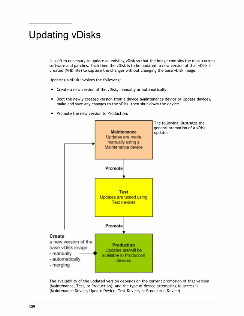
309
Updating vDisks
It is often necessary to update an existing vDisk so that the image contains the most currentsoftware and patches. Each time the vDisk is to be updated, a new version of that vDisk iscreated (VHD file) to capture the changes without changing the base vDisk image.
Updating a vDisk involves the following:
● Create a new version of the vDisk, manually or automatically.
● Boot the newly created version from a device (Maintenance device or Update device),make and save any changes to the vDisk, then shut-down the device.
● Promote the new version to Production.
The following illustrates thegeneral promotion of a vDiskupdate:
The availability of the updated version depends on the current promotion of that version(Maintenance, Test, or Production), and the type of device attempting to access it(Maintenance Device, Update Device, Test Device, or Production Device).
Update Scenarios
The following vDisk update scenarios are supported:
● Manual Update – An administrator may choose to update a vDisk manually by creating anew version of that vDisk, and then using a Maintenance device to capture updates tothat version. Manual updates are initiated by selecting the New button on the vDiskVersions dialog. The Access column on the vDisk Versioning dialog displays that thenewly created version is currently under maintenance. While under maintenance, thisversion can only be accessed and updated by a single Maintenance device. MultipleMaintenance devices can be assigned to a vDisk. However, only one device can boot andaccess that version of the vDisk at any given time. During that time that Maintenancedevice will have exclusive read/write access. For details, refer to Manually Updating avDisk Image
● Automated Update – Creating automated updates saves administration time andphysical resources. Updates are initiated on-demand or from a schedule and areconfigured using vDisk Update Management. If updating automatically, the Accesscolumn on the vDisk Versioning dialog displays that the newly created version iscurrently under maintenance. While under maintenance, this version can only beaccessed and updated by the one Update device to which it is assigned (only oneUpdate Device exists per vDisk). For details, refer to Automating vDisk Updates.
Note: vDisk Update Management is intended for use with Standard Image Mode vDisksonly. Private Image Mode vDisks can be updated using normal software distributiontool procedures. Attempting to register a Private Image Mode vDisk for vDisk UpdateManagement, or switching a vdisk that is already registered, will cause errors tooccur.
● Merge – Merging VHD differencing disk files can save disk space and increaseperformance, depending on the merge option selected. A merge update is initiatedmanually by selecting the Merge button on the vDisk Versions dialog, or automaticallywhen the maximum vDisk versions count is reached.
Updating vDisks
310
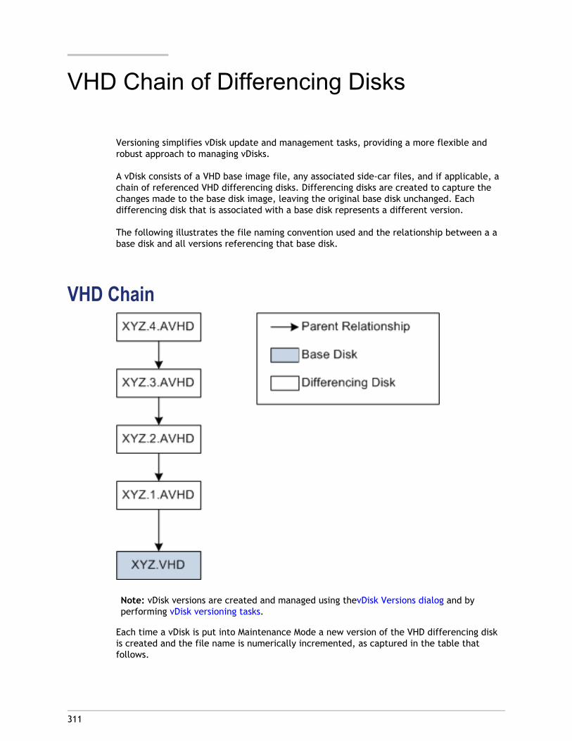
311
VHD Chain of Differencing Disks
Versioning simplifies vDisk update and management tasks, providing a more flexible androbust approach to managing vDisks.
A vDisk consists of a VHD base image file, any associated side-car files, and if applicable, achain of referenced VHD differencing disks. Differencing disks are created to capture thechanges made to the base disk image, leaving the original base disk unchanged. Eachdifferencing disk that is associated with a base disk represents a different version.
The following illustrates the file naming convention used and the relationship between a abase disk and all versions referencing that base disk.
VHD Chain
Note: vDisk versions are created and managed using thevDisk Versions dialog and byperforming vDisk versioning tasks.
Each time a vDisk is put into Maintenance Mode a new version of the VHD differencing diskis created and the file name is numerically incremented, as captured in the table thatfollows.
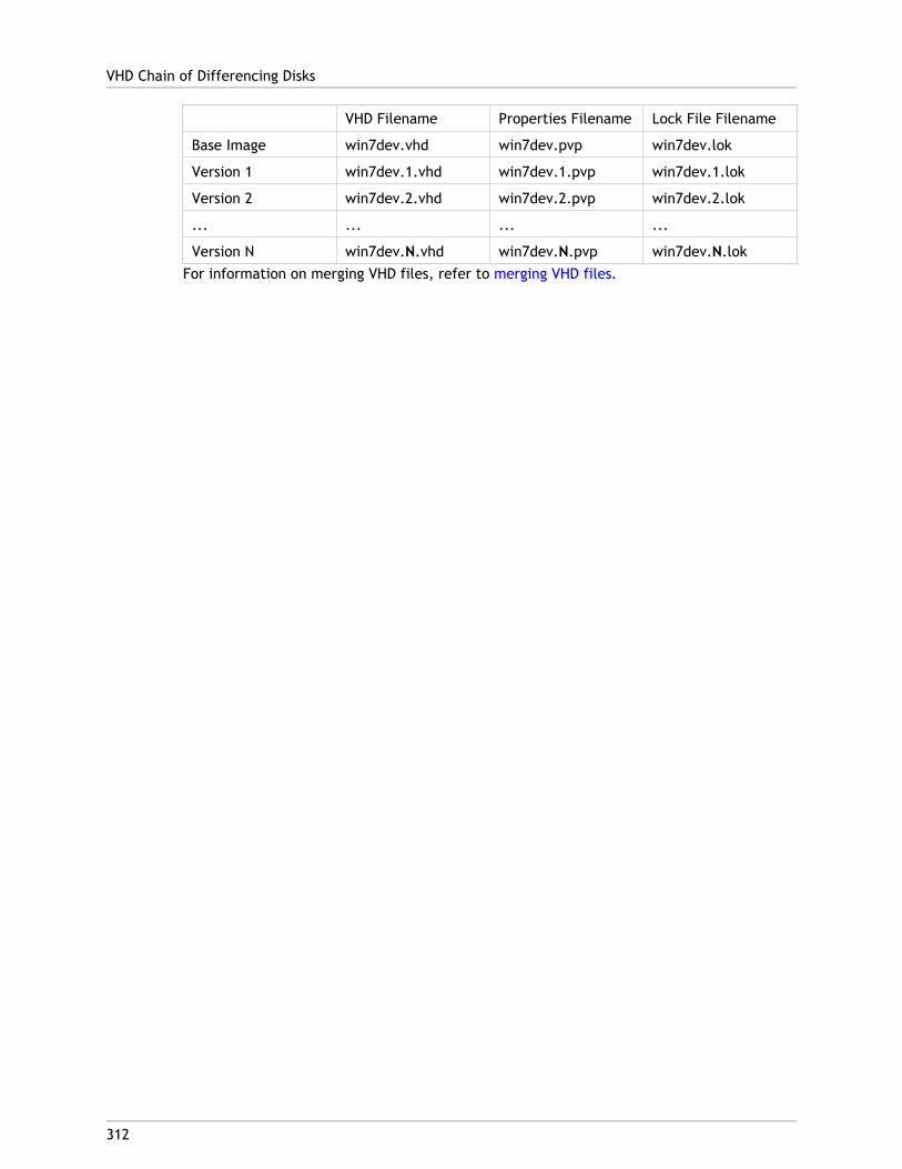
VHD Filename Properties Filename Lock File Filename
Base Image win7dev.vhd win7dev.pvp win7dev.lok
Version 1 win7dev.1.vhd win7dev.1.pvp win7dev.1.lok
Version 2 win7dev.2.vhd win7dev.2.pvp win7dev.2.lok
... ... ... ...
Version N win7dev.N.vhd win7dev.N.pvp win7dev.N.lokFor information on merging VHD files, refer to merging VHD files.
VHD Chain of Differencing Disks
312
313
Manually Updating a vDisk Image
The vDisk Versions dialog allows you to manually create a new version of the vDisk's baseimage.
Note: To automate an update process, configure for vDisk Update Management (refer toAutomating vDisk Updates).
This procedure requires that:
● a Maintenance device has been assigned to the vDisk being updated.
● no version of this vDisk is currently under maintenance.
To create a new version:
1. In the Console, right-click on a vDisk to version within a device collection or vDisk pool,then select Versions... from the context menu. The vDisk Versions dialog appears.
Note: Verify that the vDisk is currently not in Private Image mode.
2. Click New. The new version displays in the dialog with Access set to Maintenance andthe update Type method set to Manual.
3. Boot the vDisk from a Maintenance device, install or remove applications, add patches,and complete any other necessary updates, then shutdown the Maintenance device.Optionally, test that changes were made successfully.
Note: If booting a Test or Maintenance device, a boot menu displays that allows theuser to select from which vDisk, or version of that vDisk, to boot from.
4. Right-click on the vDisk, then select the Promote... menu option from the contextmenu that appears (for more details on promoting versions refer to Promoting UpdatedVersions).
5. Select to promote this maintenance version into test or directly into production. IfProduction is selected, set the availability of this version in production to be eitherimmediate or scheduled.
6. Click OK to promote this version and end maintenance.
314
Automating vDisk Updates
Note: vDisk Update Management is intended for use with Standard Image Mode vDisksonly. Private Image Mode vDisks can be updated using normal software distribution toolprocedures. Attempting to register a Private Image Mode vDisk for vDisk UpdateManagement, or switching a vdisk that is already registered, will cause errors to occur.
In the Console, the vDisk Update Management feature is used to configure the automationof vDisk updates using virtual machines (VMs). Automated vDisk updates can occur on ascheduled basis, or at any time that the administrator envokes the update directly from theConsole. This feature supports updates detected and delivered from WSUS and SCCMElectronic Software Delivery (ESD) servers.
When the Site node is expanded in the Console tree, the vDisk Update Management featureappears. When expanded, the vDisk Update Management feature includes the followingmanaged components:
● Hosts
● vDisks
● Tasks
To configure a site for vDisk Update Management requires completing the followinghigh-level tasks:
1. Designate a Provisioning Server within the site to process updates. Refer to EnablingAutomatic vDisk Updates.
2. Configuring a Virtual Host Pool for Automated vDisk updates. Refer to Using the VirtualHost Connection Wizard.
Note: Supported hypervisor types include; Citrix XenServer, MicrosoftSCVMM/Hyper-V, and VMWare vSphere/ESX.
3. Create and configure a ESD VM that will be used to update the vDisk. Refer to Creatingand Configuring ESD Update VMs.
4. Configuring vDisks for Automated updates. Refer to the Using the Managed vDisk SetupWizard.
5. Creating and managing update tasks. Refer to Using the Update Task Wizard.
Note: The user that will configure vDisk Update Management tasks must havepermissions to create, modify and delete Active Directory accounts.
6. Run the update task by right-clicking on the task object in the Console, and thenselecting the Run update now menu option. The Update VM will boot, install updatesand reboot as necessary. After the update task successfully completes, the virtualmachine is automatically shutdown. The update status can be checked from the Consoletree under vDisk Update Management>vDisks>(vDisk name)> Completed Update Status.The status can also be checked using the event viewer or in WSUS.
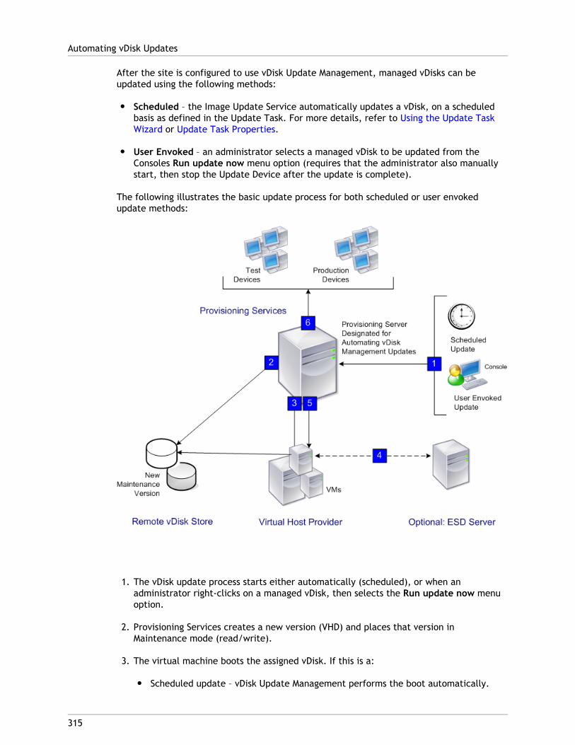
After the site is configured to use vDisk Update Management, managed vDisks can beupdated using the following methods:
● Scheduled – the Image Update Service automatically updates a vDisk, on a scheduledbasis as defined in the Update Task. For more details, refer to Using the Update TaskWizard or Update Task Properties.
● User Envoked – an administrator selects a managed vDisk to be updated from theConsoles Run update now menu option (requires that the administrator also manuallystart, then stop the Update Device after the update is complete).
The following illustrates the basic update process for both scheduled or user envokedupdate methods:
1. The vDisk update process starts either automatically (scheduled), or when anadministrator right-clicks on a managed vDisk, then selects the Run update now menuoption.
2. Provisioning Services creates a new version (VHD) and places that version inMaintenance mode (read/write).
3. The virtual machine boots the assigned vDisk. If this is a:
● Scheduled update – vDisk Update Management performs the boot automatically.
Automating vDisk Updates
315
● User envoked update – the administrator envokes the update.
4. All updates are automatically made and captured in the new version of the VHD file.
5. After updating the vDisk, the virtual machine is shut down automatically.
6. The vDisk is promoted from Maintenance to either Test or Production. The availabilityof the new vDisk version depends on the Access mode that was selected when theUpdate Task Wizard was run, or the mode that is currently selected on the Update TaskProperties' Finish tab (Maintenance, Test, or Production). After this version is madeavailable in production, target devices will be able to access it the next time they bootthat vDisk.
Automating vDisk Updates
316
317
Enabling Automatic vDisk Updates
To allow Managed vDisks to be updated automatically:
1. Right-click on the Site in the Console, then select the Properties menu option. The SiteProperties dialog appears
2. On the vDisk Update tab, check the box next to Enable automatic vDisk updates onthis site.
3. Scroll to select the server to run vDisk updates for this site, then click OK.
Managed vDisks can now be automatically updated on this site. Next, virtual hostconnections must be configured to allow for automatic updates to be made. Refer toConfiguring Virtual Host Connections for Automated vDisk Updates.
318
Configuring Virtual Host Connections forAutomated vDisk Updates
To use vDisk Update Management, a designated hypervisor server is selected from within avirtual pool that is then used to communicate with Provisioning Services. This isaccomplished by running the Virtual Host Connection Wizard.
Note: If running a vCenter server on alternate ports, the following registry modificationsmust be made in order to connect to it from Provisioning Services:
Create a new registry key named PlatformEsx underHKLM\Software\Citrix\ProvisioningServices
Create a new string value in the PlatformEsx key named ServerConnectionString and setit to http://{0}:PORT#/sdk
(If using use port 300, ServerConnectionString= http://{0}:300/sdk)
To configure virtual host connections:
1. Under the vDisk Update Management node in the Console tree, right-click on Hosts,then select the Add host... option. The Virtual Host Connection Wizard appears.
2. Click Next to begin. The Hypervisor page appears.
3. Select the radio button next to the type of hypervisor used by this pool, then clickNext:
● Citrix XenServer
● Microsoft SCVMM/Hyper-V
● VMWare vSphere/ESXThe Name/Description page appears.
4. Enter the name, and optionally a description, for the Virtual Host Connection then clickNext.
5. Enter the hostname or the IP address of the server to contact.
Note: It can take several minutes before a hostname/IP address can be re-entered, ifthat hostname/IP was previously entered and then deleted.
6. Click Next. The Credentials page appears.
7. Enter the appropriate credentials required to connect to this host, then click Next:
● Username – the account name with appropriate permissions to access the virtualhost pool server.

● Password – password used with this account name.
The Confirmation page appears.
8. Review all settings are accurate, then click Finish.
Virtual Host Pool properties can be viewed or modified on the Virtual Host ConnectionProperties dialog.
Configuring Virtual Host Connections for Automated vDisk Updates
319
320
Virtual Host Connection Properties
After a virtual host connection is created using the Virtual Host Connection Wizard, it canbe viewed or modified on the Virtual Host Pool Properties tabs:
● General
● Credentials
● Advanced
General TabField/button Description
Type The type of virtual host connection that was selected whenthe Virtual Host Connection Wizard was run. This field cannotbe modified.
Name The name to use when referencing this virtual hostconnection by Provisioning Services.
Description A brief description of this virtual host connection.
Host The hostname or IP address of the virtual host connectionserver for Provisioning Services to contact.
Note: If running a vCenter server on alternate ports, thefollowing registry modifications must be made in order toconnect to it from Provisioning Services:
● Create a new keyHKLM\Software\Citrix\ProvisioningServices\PlatformEsx
● Create a new string in the PlatformEsx key named'ServerConnectionString' and set it to'http://{0}:PORT#/sdk'
(If using use port 300, ServerConnectionString=http://{0}:300/sdk)
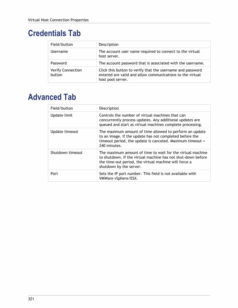
Credentials TabField/button Description
Username The account user name required to connect to the virtualhost server.
Password The account password that is associated with the username.
Verify Connectionbutton
Click this button to verify that the username and passwordentered are valid and allow communications to the virtualhost pool server.
Advanced TabField/button Description
Update limit Controls the number of virtual machines that canconcurrently process updates. Any additional updates arequeued and start as virtual machines complete processing.
Update timeout The maximum amount of time allowed to perform an updateto an image. If the update has not completed before thetimeout period, the update is canceled. Maximum timeout =240 minutes.
Shutdown timeout The maximum amount of time to wait for the virtual machineto shutdown. If the virtual machine has not shut-down beforethe time-out period, the virtual machine will force ashutdown by the server.
Port Sets the IP port number. This field is not available withVMWare vSphere/ESX.
Virtual Host Connection Properties
321
322
Creating and Configuring ESD UpdateVMs
Virtual machines (VMs) that are used to update a Managed vDisk must first be created onthe hypervisor prior to configuring for vDisk Update Management in Provisioning Services.Supported hypervisors include; Citrix Xenserver, Microsoft SCVMM/Hyper-V, and VMWarevSphere/ESX.
The type of ESD determines the specific steps involved in creating and configuring the VMon the hypervisor. However the following general prerequisites apply to Update VMsregardless of the ESD system selected:
● Download, install, and configure the appropriate ESD Server software on the server.
● A VM must be uniquely named on the hypervisor and follow naming conventionsequivalent to a Provisioning Services target device name. The name can be up to 15bytes in length.
● Only one VM should exist for a Managed vDisk because only one update task can occuron that vDisk at any given time.
● Citrix recommends allocating at least 2GBs of memory for each VM and stronglyrecommends using Windows 7 as the client OS.
● Appropriate ESD licenses must be made available and the ESD client software must beproperly installed and enabled on the vDisk.
● Using Microsoft HyperV Server without SCVMM is not supported.
● Configuring the Update VM, that is used to build the Update vdisk, with multiple nicswhen streaming to SCVMM server fails to PXE boot. Citrix suggests using a single NIC oruse only one Legacy NIC.
● Because the image update client requires .NET 3.5 or higher, it must be installed on thevDisk that serves the update VM.
● Citrix recommends to only apply updates that can be downloaded and installed in 30minutes or less.
The following ESD systems are supported:
● WSUS
● SCCM
Creating and Configuring a WSUS Update VM
1. Under the server hypervisor, create and boot up a client. For the purpose of providingan example, the client VM NameA (client VMs must be unique on the hypervisor).
2. Add the client VM (NameA) to the domain and make any other settings specific to yourenvironment.
3. Install the Provisioning Services Target Device software on the client VM (NameA).
4. Build a vDisk image from the client VM (NameA), and when prompted, you must enter atarget device name. For the purpose of this example, the target device name will beNameB.
5. After successfully building the vDisk image, shutdown the target device.
6. Optional. If using Active Directory, enable Active Directory on the vDisk and then createa machine account for the target device (NameB) using the Provisioning ServicesConsole.
7. In the Console, set the target device to boot from the vDisk image in Private Imagemode.
8. Boot the target device, then complete the following:
a. Verify that the Windows firewall setting is set to Off.
b. Run Gpedit.msc navigate to: Computer Configurations>Administrativetemplates>Windows Components>Windows Update>Specify the Intranet Microsoftupdate service location and set to be Enabled.
c. Enter the name of the WSUS server (from step one) under the Set the intranetupdate service for detecting updates and Set the intranet statistics server name(http://WSUS-SERVER-NAME).
d. Install the Windows Update Agent specific to the platform from:http://support.mirosoft.com/kb/949104.
e. Restart the target device to configure the Windows Update Agent.9. Shutdown the target device.
10. On the hypervisor, create a diskless VM to serve as the Update VM (NameC), then setthe Update VM to boot from the network (do not boot).
11. From the WSUS server, approve the updates for your client VM
12. From the Console,
a. Set the Access Mode for the vDisk to Standard Image mode, on the vDisk PropertiesGeneral tab.
b. Configure the host connection, refer to Configure virtual host connections forautomated vDisk updates.
c. Configure a managed vDisk for automated updates. Refer to Configure ManagedvDisks for automated updates.
Creating and Configuring ESD Update VMs
323

d. Create an update task. Refer to Create an update task.
Creating and Configuring ESD Update VMs
324
Creating and Configuring a SCCM Update VM1. Under the server hypervisor, create and boot up a VM client. For the purpose of
providing an example, the client VM will be named NameA (client VMs must be uniqueon the hypervisor).
2. Add the client VM (NameA) to the domain, and then make any additional settingsspecific to your environment.
3. Install the SCCM client agent on the client VM, by either pushing the SCCM client installfrom SCCM or by using the manual method. (Refer to SCCM documentation for details).Verify that the SCCM client agent was successfully installed on the client, and thencheck that the client (NameA) is listed as Client=Yes & Approved on the SCCM server.
4. Install the Provisioning Services Target Device software and build a vDisk image of theclient (NameA). While building the image, you will be prompted to enter a targetdevice name. You must enter a temporary VM name (for example: NameB). This namemust not be the same as the VM name.
5. After the image is successfully built, shutdown the target device.
6. On the Provisioning Services Console:
a. To allow for the SCCM server to recognize the client, rename the target devicefrom the temporary name (NameB) to the desired name (NameA).
b. Set the Target Device to boot from the vDisk.
c. Select the Private Image vDisk access mode from the vDisk Properties General tab.
d. If this is a Active Directory environment, enable the Active Directory option on thevDisk image previously created, then create the machine account for this device.
7. Boot the target device, then:
a. Verify the Windows firewall setting is set to Off.
b. Open the services console and set the startup type of the SMS Agent Host servicesto Manual.
c. Install the Windows update agent that is specific to the platform (refer tohttp://support.microsoft.com/kb/949104).
d. Restart the target device to configure the Windows Update Agent.8. Shutdown the Target Device.
9. On the SCCM Server:
a. Create a deployment package for distribution to the SCCM client systems.
b. Do not apply a deadline to the package.10. In the Provisioning Services Console:
a. Delete the Active Directory settings (AD machine account) previously associatedwith the target device that was created.
Creating and Configuring ESD Update VMs
325
b. Delete the target device (DO NOT delete the VHD).
11. In the Console,
a. Set the Access Mode for the vDisk to Standard Image mode, on the vDisk PropertiesGeneral tab.
b. Configure the host connection, refer to Configure virtual host connections forautomated vDisk updates.
c. Configure a managed vDisk for automated updates. Refer to Configure ManagedvDisks for automated updates.
d. Create an update task. Refer to Create an update task.
Creating and Configuring ESD Update VMs
326
327
Configuring Managed vDisks forAutomated Updates
vDisk Update Management uses virtual machines to process updates to managed vDisk(s).vDisks are first created in the Console, then added to vDisk Update Manager as managedvDisks by running the Managed vDisk Setup Wizard.
Note: If using ESD Servers to deliver updates, the ESD client software must be installedand enabled on the vDisk, and appropriate ESD licensing must also be available.
1. Under the vDisk Update Management node in the Console tree, right-click on vDisks,then select the Add vDisks... option. The Managed vDisk Setup Wizard Welcome pageappears.
2. Click Next to begin. The vDisk page appears.
3. Select the default search options (All stores, All servers) or use the filtering options toselect specific stores and/or servers to display the vDisk(s) to select to be managed.vDisks that are not already managed will display in the vDisk selection box.
4. Select one or more vDisks to be managed, then click Next. The Host/VM page appears.
5. Select the type of connection to use when hosting the VM, from the appropriatedrop-down list .
6. Enter the name of the Update VM used to process the vDisk update. The VM name fieldis case sensitive and must match exactly to the existing VM name on the desiredhypervisor.
7. Click Next. The Active Directory page appears.
8. If using Active Directory, enter a Domain and Organizational Unit to create an ActiveDirectory machine account that will be used by the Update Device that is createdexclusively for updating this vDisk, then click Next. The Confirmation page appears.
Note: The Update VM should not already pre-exist in the Provisioning Servicesdatabase or Active Directory. If it does exist, the wizard will not run successfully.
9. Review all setting, then click Finish.
The Managed vDisk Setup Wizard can also be run from the Managed vDisk dialog.

328
Managed vDisk Dialog
The Managed vDisk dialog displays all Managed vDisks currently in the store. The ManagedvDisk Setup Wizard can be run from the Managed vDisk Dialog by clicking on the AddManaged vDisks button.
329
Creating and Managing Tasks
Note: The user that will configure vDisk Update Management tasks must have permissionsto create, modify and delete Active Directory accounts.
Use the Update Task Wizard to schedule vDisk updates to run automatically:
1. Under the vDisk Update Management node in the Console tree, right-click on Task, thenselect the Add task... menu option. The Update Task Wizard welcome page appears.
2. Click Next to begin configuring a task. The Name/Description page appears.
3. Enter a name (required) to identify this task, and a description (optional) in theappropriate text boxes, then click Next. The Schedule page appears.
4. Select one of the radio buttons to determine how often this task will run; None, Daily,Weekly, or Monthly. Depending on which recurrence option was selected, the pagedisplays options specific to that selection:
● None – no additional options appear
● Daily
● Run the update at – select the time of day to run the daily update from thedrop-down menu or enter a specific time.
● Everyday – select to run this daily update everyday of the week: Mondaythrough Sunday.
● Weekdays only – select to run this daily update on weekdays only: Mondaythrough Friday.
● Weekly
● Run the update at – select the time of day to run the daily update from thedrop-down menu or enter a specific time.
● Select specific days of the week to run the update.
Note: At least one day must be selected to proceed.● Monthly
● Run the update at – select the time of day to run the daily update from thedrop-down menu or enter a specific time.
● Select to run the update task on specific days of the month using one of thefollowing methods: On Date – enter which days of the month to run the update.
Note: Only numbers and commas are accepted in this text box. For example:1,15 runs this update task on the first and fifteenth of every month. If either29 or 31 are entered, this task will not run every month.
Or, select On, to select the week and day of the week from the drop-downmenus. For example: Selecting First and Monday would run the task on the firstMonday of every month.
5. Click Next. The vDisks page appears.
6. Highlight existing Managed vDisks that will be updated using this new task, then clickOK. Optionally, click on the Add Managed vDisks button run the Managed vDisk SetupWizard in order to add new managed vDisks to the list; after the wizard completes, thenew managed vDisks display in the list and can be selected.
7. Click Next. The ESD Client page appears.
8. Select the type of Electronic Software Delivery (ESD) client that is running on the vDisk,from the drop-down list, then click Next.
Note: The ESD client software must already be installed in the vDisk image.
Note: When the option is set to None, client-side scripts can be run if the scripts arestored on the vDisk prior to the update. These scripts need to be stored under theinstallation directory of the client. Update.bat is a mandatory script. Optional scriptsinclude Preupdate.bat and Postupdate.bat, which are dependant on the usersconfiguration.
9. Optionally, select from the following scripting options, then click Next:
● Pre-update script – executes prior to the start of any update task process.
● Pre-startup script – executes just before startup of the virtual machine.
● Post-shutdown script – executes just after the virtual machine shuts down.
● Post update script – executes after the update task process completes.
Note: On the server, a sub-folder name Scripts must be created under the productinstallation directory. This folder is used to store server-side scripts.
10. On the vDisk Access page, select the post-update access mode to assign to the vDiskversion, then click Next:
● Leave the vDisk in Maintenance mode (only available to Maintenance Devices)
● Place the vDisk in Test mode (only available to Test and Maintenance Devices)
● Make the vDisk ready for use (Production, available to all target devices)11. Confirm that all vDisk Update Task settings are correct, then click Finish to create the
new task.
vDisk Update Tasks can be viewed and modified on the Update Task Properties dialog.
Creating and Managing Tasks
330
331
Using Windows Task Scheduler to CreatevDisk Update Task Scripts
Windows Task Scheduler can be used to create vDisk Update task scripts. These scripts areassociated with a task when the Update Task Wizard is run and can later be modified on theScripts tab of the vDisk Update Task Properties dialog.
Note: Features of the Task Scheduler are used to run the batch file/script as the desireduser.
The following types of task scripts can be created:
● Pre-update script - executes prior to the start of any update task process.
● Pre-startup script - executes just before starting the virtual machine.
● Post-shutdown script - executes just after the virtual machine shuts down.
● Post update script - executes after the update task process completes.
Scripts are stored in a Scripts folder, which is a sub-folder of the product installationfolder.
A sample batch file to boot target devices:
Mcli SetupConnection /p server=192.168.1.1
Mcli Run Boot /p deviceMac=00-00-00-00-00-11
Mcli SetupConnection /p server=192.168.1.1
Mcli Run Boot /p deviceMac=00-00-00-00-00-11
Mcli Run Boot /p deviceMac=00-00-00-00-00-22
Mcli Run Boot /p deviceMac=00-00-00-00-00-33
Mcli Run Boot /p deviceMac=00-00-00-00-00-44
Mcli Run Boot /p siteName=Boston collectionName=Sales
A sample batch file to check for vDisk updates:
Mcli SetupConnection /p server=192.168.1.1
Mcli Run ApplyAutoUpdate /p siteName=Boston
Note: When configuring the server connection using the Mcli-Run SetupConnectioncommand, do not specify the user, password, or domain as these values will not beprotected in the batch file/script.
To create a script, complete either the Windows 2008 R2 Task Scheduler procedure or theWindows 2003 R2 Task Scheduler procedure.
Creating an Update Task Using Windows 2008 R2Task Scheduler
1. Start the Task Scheduler from the Start Menu (Start>All Programs>Accessories>SystemTools>Task Scheduler). The Task Scheduler dialog appears.
2. From the Action menu, select the Create Task... menu option. The Create Task dialogappears.
3. On the General tab, type a name and a description to associate with this task.
4. If necessary, click Change User or Group... to select a different user to run the batchfile/script.
5. Select the Run whether user is loggon on or not radio button.
6. On the Triggers tab, click New... to begin creating a schedule for this task.
7. Select how this task should begin from the Begin the task: drop-down list.
8. Select how often to perform this task by enabling the radio button next to theappropriate option.
9. Enter or scroll to set the start date and the time of day this task should run.
10. Optionally, enable or disable any advanced settings.
11. Click OK to close the dialog.
12. On the Actions tab, click New.... The New Action dialog appears.
13. From the Action drop-down menu, select the action that this task will perform.
14. In the Program/script: text box, type or browse for the name of the batch file/script,then click OK.
15. Optionally, configure additional task configuration settings on the Conditions andSettings tabs.
16. Click OK to close the dialog.
17. If prompted, enter the password for the user running the file/script, then click OK toclose the dialog.
18. In the Task Scheduler window, select the Task Scheduler Library node in the left panetree. The new task should appear in the center pane of the window.
Using Windows Task Scheduler to Create vDisk Update Task Scripts
332
Creating an Update Task Using Windows 2003 R2Task Scheduler
1. Start the Task Scheduler for the Start Menu (Start>All Programs>Accessories>SystemTools>Scheduled Tasks). The Scheduled Tasks dialog appears.
2. Click Add Scheduled Task. The Scheduled Task Wizard appears.
3. Click Next to continue.
4. Click Browse... then select the program to use to run the batch file/script.
5. Click Next, then enter a name for the task.
Note: This name can be the same name as the program previously chosen to run thebatch file/script.
6. Select when to perform this task by enabling the radio button next to the appropriateoption, then click Next.
7. Under Start time:, enter or scroll to set the time of day this task should run.
8. Under Perform this task:, select the radio button next to the appropriate day criteria.
9. Under Start date:, select the starting date for this task. then click Next.
10. Enter the credentials for the user that will execute the task, then click Next.
11. The confirmation page displays with a task configuration summary. After reviewingconfiguration settings, click Finish to complete the creation of this task.
Using Windows Task Scheduler to Create vDisk Update Task Scripts
333
334
vDisk Update Task Properties
After a task is created using the Update Task Wizard, it can be modified from the followingUpdate Task Properties tabs:
● General
● Schedule
● vDisks
● ESD
● Scripts
● Access
General TabName and Description
Enter a name (required) to identify this task, and a description (optional) in theappropriate text boxes.
Disable this task
If enabled, temporarily disables the update task.
Schedule TabRecurrence
Select one of the radio buttons to determine how often this task will run:
● None
● Daily
● Weekly
● MonthlyDepending on which recurrence option is selected, the page displays options specific tothat selection.
● None – no additional options appear
● Daily
● Run the update at – select the time of day to run the daily update from thedrop-down menu or enter a specific time.
● Everyday – select to run this daily update everyday of the week: Monday throughSunday.
● Weekdays only – select to run this daily update on weekdays only; Mondaythrough Friday.
● Weekly
● Run the update at – select the time of day to run the daily update from thedrop-down menu or enter a specific time.
● Select specific days of the week to run the update.
Note: At least one day must be selected to proceed.● Monthly
● Run the update at – select the time of day to run the daily update from thedrop-down menu or enter a specific time.
● Select to run the update task on specific days of the month using on of thefollowing methods: On Date – enter which days of the month to run the update.
Note: Only numbers and commas are accepted in this text box. For example:1,15 runs this update task on the first and fifteenth of every month. If either29 or 31 are entered, this task will not run every month.
Or, select On to select the week and day from the drop-down menus. Forexample: Selecting First and Monday would run the task on the first Monday ofevery month.
vDisks TabvDisk
Lists Managed vDisks.
Virtual Host Pool
Lists the Virtual Host Pool (host) that communicates with Provisioning Services in orderto be updates.
VM
Lists Managed devices used to update the vDisk.
Add
Opens the Managed vDisk dialog, from which additional Managed vDisks can be selected(refer to Configuring Managed vDisks for Automated Updates
vDisk Update Task Properties
335
Remove
Removes Managed vDisks from the list of vDisks to update with this task.
ESD TabSelect ESD client to use
Select from the supported Electronic Software Device (ESD) types.
Note: When the option is set to None, client-side scripts can be run if the scripts arestored on the vDisk prior to the update. These scripts need to be stored under theinstallation directory of the client. Update.bat is a mandatory script. Optional scriptsinclude Preupdate.bat and Postupdate.bat, which are dependant on the usersconfiguration.
Scripts TabScripts that should execute with the vDisk update task process
Optional:
● Pre-update script – executes prior to the start of any update task process.
● Pre-startup script – executes just before starting the virtual machine.
● Post-shutdown script – executes just after the virtual machine shuts down.
● Post update script – executes after the update task process completes.
Access TabUpon successful completion of the update, select the access to assign to the vDisk
Leave the vDisk in Maintenance mode (only available to Maintenance Devices)
Place the vDisk in Test mode (only available to Test and Maintenance Devices)
Make the vDisk ready for use in Production (available to all target devices)
vDisk Update Task Properties
336
337
Updating vDisks on Demand
To make an unscheduled update to a Managed vDisk:
Under the vDisk Update Management node in the Console tree, right-click on a ManagedvDisk, then select Run update now menu option. If the vDisk is included in more than onetask, a dialog displays the tasks from which you can choose. Updating on demand requiresthat the administrator manually start the Update Device, and then wait until it completesthe update successfully.
338
Update Device Properties
To view or modify Update Device properties, right-click on the device in the Console, thenselect the Properties menu option. The tables that follow identify the tabs and describefields and options on those tabs.
● General
● Personality
● Status
● Logging
General TabvDisk
Displays the vDisk that is assigned to this Update device. This field cannot be modified.Each Managed Device has a one-to-one relationship with a single vDisk of the same name.
Virtual Host Connection
Displays the name of the virtual host server assigned to this device. This field cannot bemodified
VM Name
The name of the virtual machine on the virtual host provider. This field cannot bemodified.
VM MAC
The media access control (MAC) address of the network interface card that is installed inthe Update device. This field cannot be modified.
VM Port
Provides the UDP port value. In most instances, the port number does not have to bemodified. However, if Update device software conflicts with any other IP/UDP software(that is, they are sharing the same port), this value must be changed.
Personality TabName and String
There is no fixed limit to the number of names you can add. However, the maximumname length is 250 characters and the maximum value length is 1000 characters.
Use any name for the field Name, but do not repeat a field name in the same device.Field names are not case sensitive. In other words, the system interprets “FIELDNAME”and “fieldname” as the same name. Blank spaces entered before or after the field nameare automatically removed.
A personality name cannot start with a $. This symbol is used for reserved values such as$DiskName and $WriteCacheType.
On this tab, a new personality string can be created, or an existing string modified orremoved.
Status TabStatus
The following device status information appears:
● Update Status: displays the status of the update as either inactive or active (updatein progress).
● Status: current status of the device (active or inactive).
● IP Address: provides the IP Address or 'unknown'.
● Server: the Provisioning Server that is communicating with this device.
● Retries: the number of retries to permit when connecting to this device.
● vDisk: provides the name of the vDisk or displays as 'unknown'.
● License information; depending on the device vendor, displays product licensinginformation (including; n/a, Desktop License, Datacenter License, XenApp License,or XenDesktop License).
Logging TabLogging level
Select the logging level or select Off to disable logging:
● Off – Logging is disabled for this Provisioning Server.
● Fatal– logs information about an operation that the system could not recover from.
● Error logs information about an operation that produces an error condition.
● Warning– logs information about an operation that completes successfully, but thereare issues with the operation.
Update Device Properties
339

● Info – Default logging level. Logs information about workflow, which generallyexplains how operations occur.
● Debug – logs details related to a specific operation and is the highest level oflogging. If logging is set to DEBUG, all other levels of logging information aredisplayed in the log file.
● Trace – logs all valid operations.
Update Device Properties
340
341
Merging VHD Differencing Disks
Merging VHD differencing disk files can save disk space and increase performance,depending on the merge method selected.
Merge methods include:
● Merging to a new base image
● Merging to a consolidated differencing disk
Note: A merge can only occur when no Maintenance version exists for this vDisk or whenthe vDisk is in Private Image mode. A merge starts from the top of the chain down to abase disk. A starting disk cannot be specified for the merge.
Merging to a New Base ImageA full merge to a new base image combines a chain of differencing disks and base imagedisks into a new single base disk. This new disk is the next version in the chain, which isgiven the file extension of .VHD. This method allows for the fastest disk access to the baseimage and is recommended when performance is more important than disk space (a newbase disk is created for every merge performed).
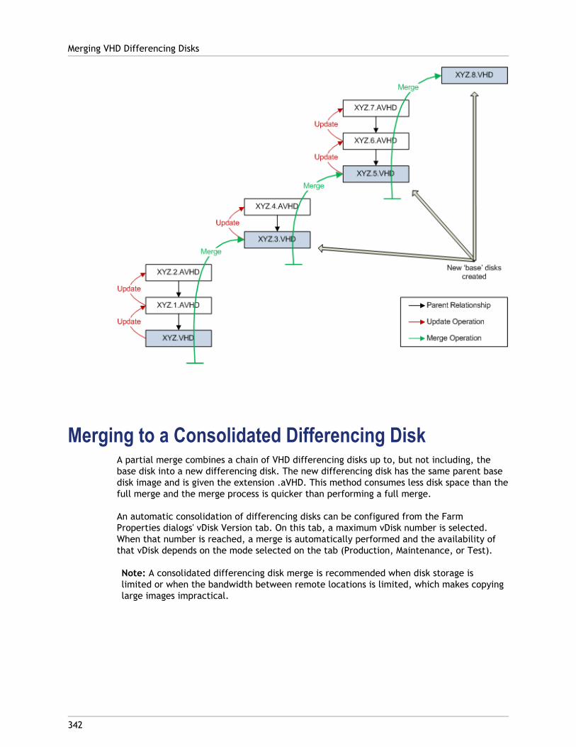
Merging to a Consolidated Differencing DiskA partial merge combines a chain of VHD differencing disks up to, but not including, thebase disk into a new differencing disk. The new differencing disk has the same parent basedisk image and is given the extension .aVHD. This method consumes less disk space than thefull merge and the merge process is quicker than performing a full merge.
An automatic consolidation of differencing disks can be configured from the FarmProperties dialogs' vDisk Version tab. On this tab, a maximum vDisk number is selected.When that number is reached, a merge is automatically performed and the availability ofthat vDisk depends on the mode selected on the tab (Production, Maintenance, or Test).
Note: A consolidated differencing disk merge is recommended when disk storage islimited or when the bandwidth between remote locations is limited, which makes copyinglarge images impractical.
Merging VHD Differencing Disks
342
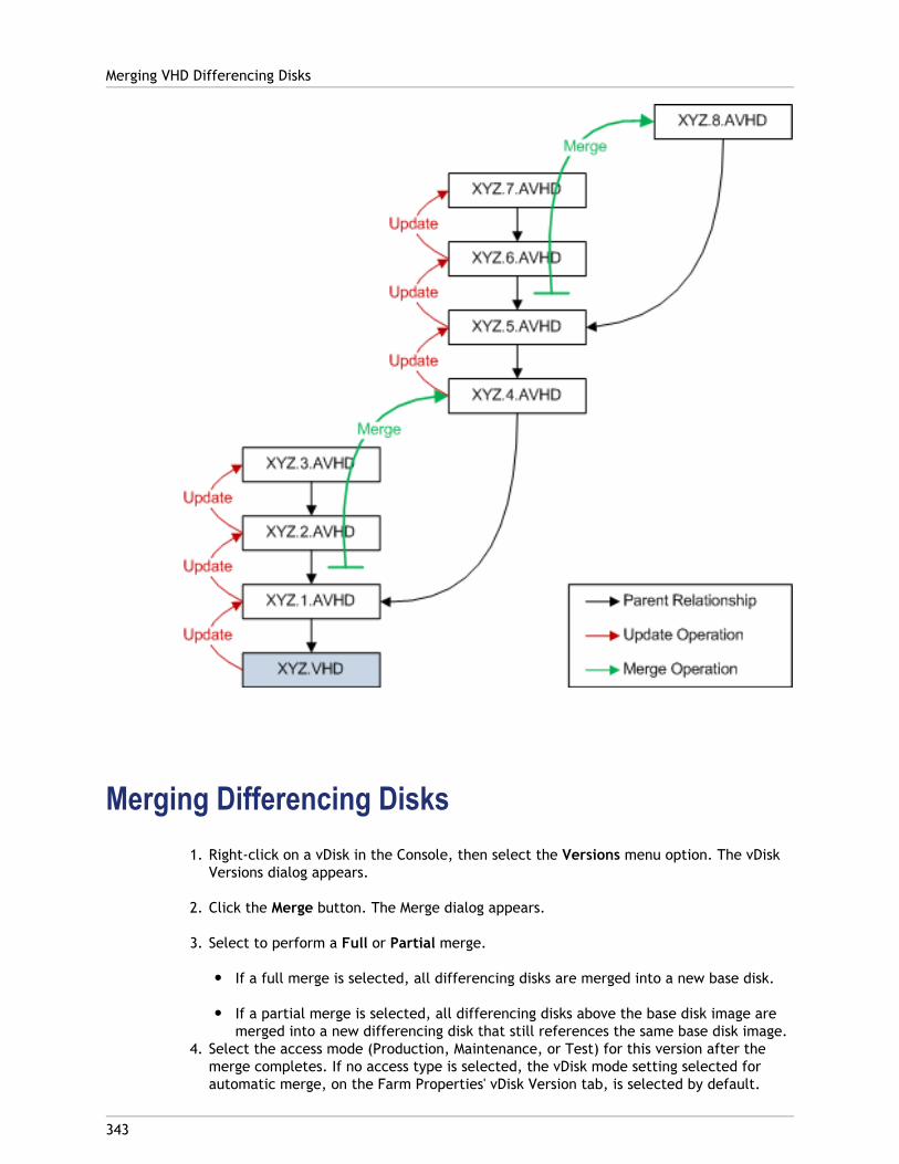
Merging Differencing Disks1. Right-click on a vDisk in the Console, then select the Versions menu option. The vDisk
Versions dialog appears.
2. Click the Merge button. The Merge dialog appears.
3. Select to perform a Full or Partial merge.
● If a full merge is selected, all differencing disks are merged into a new base disk.
● If a partial merge is selected, all differencing disks above the base disk image aremerged into a new differencing disk that still references the same base disk image.
4. Select the access mode (Production, Maintenance, or Test) for this version after themerge completes. If no access type is selected, the vDisk mode setting selected forautomatic merge, on the Farm Properties' vDisk Version tab, is selected by default.
Merging VHD Differencing Disks
343

5. Click OK to begin the merge process.
The time it takes to complete the merge process varies based on the merge methodselected and the number of differencing disks to merge. After the merge successfullycompletes, the new version displays in the vDisk Versions dialog. The Type column displayseither Merge Base if a full merge was selected, or Merge if a partial merge was selected.
Merging VHD Differencing Disks
344
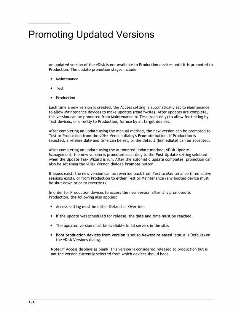
345
Promoting Updated Versions
An updated version of the vDisk is not available to Production devices until it is promoted toProduction. The update promotion stages include:
● Maintenance
● Test
● Production
Each time a new version is created, the Access setting is automatically set to Maintenanceto allow Maintenance devices to make updates (read/write). After updates are complete,this version can be promoted from Maintenance to Test (read-only) to allow for testing byTest devices, or directly to Production, for use by all target devices.
After completing an update using the manual method, the new version can be promoted toTest or Production from the vDisk Version dialog's Promote button. If Production isselected, a release date and time can be set, or the default (Immediate) can be accepted.
After completing an update using the automated update method, vDisk UpdateManagement, the new version is promoted according to the Post Update setting selectedwhen the Update Task Wizard is run. After the automatic update completes, promotion canalso be set using the vDisk Version dialog's Promote button.
If issues exist, the new version can be reverted back from Test to Maintenance (if no activesessions exist), or from Production to either Test or Maintenance (any booted device mustbe shut down prior to reverting).
In order for Production devices to access the new version after it is promoted toProduction, the following also applies:
● Access setting must be either Default or Override.
● If the update was scheduled for release, the date and time must be reached.
● The updated version must be available to all servers in the site.
● Boot production devices from version is set to Newest released (status is Default) onthe vDisk Versions dialog.
Note: If Access displays as blank, this version is considered released to production but isnot the version currently selected from which devices should boot.
346
Retiring or Deleting vDisks
When a vDisk is no longer needed, it can be retired. Retire a vDisk by deleting it. When avDisk is deleted, all VHD differencing disk files, properties files, lock files, and differencecache are also deleted.
Note: You cannot delete a vDisk if one or more target devices are currently assigned toit. Unassign all target devices from the vDisk, before attempting to delete it.
To delete a vDisk:
1. In the Console, expand vDisk Pool in the tree, then highlight the vDisk that you want todelete in the details pane.
2. Right-click on the vDisk, then select Delete. The Delete vDisks dialog appears.
3. To permanently delete the vDisk from the hard drive, select the checkbox for deletingthe vDisk from the hard drive option. Or, do not select the checkbox to delete the vDiskfrom the store and database. Unless a backup copy is made before deleting a vDiskimage file from the store, the vDisk image file is permanently deleted.
4. Click Yes. The vDisk is deleted.
347
Managing Device Collections
Device collections provide the ability to create and manage logical groups of target devices.Creating device collections simplifies device management by performing actions at thecollection level rather than at the target-device level.
Note: A target device can only be a member of one device collection.
A device collection could represent a physical location, a subnet range, or a logicalgrouping of target devices. For example, a collection could consist of all target devices thatuse a particular vDisk image, and that target device collection might consist ofmaintenance, test, and production devices. Alternativaly, three device collections couldexist for a particular vDisk; one consisting of production devices, one consisting of testmachines, and another consisting of maintenance machines. In the proceeding examples, allof the devices in a given collection are assigned to the same vDisk.
Depending on a sites preference, another collection use case might include theconsolidation of test and/or maintenance devices into a single device collection, and thenmanaging vDisk assignments on a per device basis rather than a per collection basis. Forexample, create a device collection labeled Development consisting of five target devices,each one assigned to a particular vDisk.
Device collections are created and managed by farm administrators, site administratorsthat have security privileges to that site, or device administrators that have securityprivileges to that collection. For more information on administrator roles, refer to ManagingAdministrative Roles.
Expanding a Device Collections folder in the Console’s tree allows you to view members of adevice collection. To display or edit a device collection’s properties, right-click on anexisting device collection in the Console, then select the Properties menu option. TheDevice Collection Properties dialog displays allowing you to view or make modifications tothat collection.
To perform actions on members of a device collection, such as rebooting all target devicesmembers in this collection, refer to “Device Collection Management Tasks”.
348
Device Collection Properties
Device collection properties are located on the following tabs and described in the tablesthat follow.
● General Tab
● Security Tab
● Auto-Add
General TabField/Button Description
Name The name of this device collection.
Description Describes this device collection.
Template target device To use the settings of an existing targetdevice as the template to apply to alltarget devices that are added to thiscollection, select that device from thedrop-down menu, then click OK.
Security TabField/Button Description
Groups withDeviceAdministratoraccess
Assign or unassign device administrators to this collection using Addor Remove. Device administrators can perform tasks on all devicecollections to which they have privileges.
Groups withDevice Operatoraccess
Assign or unassign device operators to this collection using Add orRemove. Device operators have the following privileges:
● Boot and reboot a target device
● Shut down a target device
● View target device properties
● View vDisk properties for assigned target devices

Auto-Add TabField/Button Description
Template targetdevice
Displays the name of the target device, if a device was previouslyselected, or <No template device>, if a device was not selected.
Use the drop-down menu to select a device to use as the templatefor adding new devices to this collection.
To view a selected device's properties, click Properties (read-onlydialog appears).
Prefix Enter a static prefix that helps identify all devices that are beingadded to this collection. For example: 'Boston' to indicate deviceslocated in Boston.
The prefix can be used in combination with the suffix, but is notrequired if a suffix is provided. The entire device name can have amaximum of 15 characters (the prefix length + number length +suffix length). For example, the following device names areconsidered valid:
● Boston000Floor2 (prefix, incrementing number length, andsuffix provided; the maximum of 15 characters has beenreached)
● Boston000 (no suffix is provided)
● 000Floor2 (no prefix is provided)
The prefix cannot end with a digit.
The prefix and suffix combination must be unique in eachcollection.
Number Length Enter the length of the incrementing number to associate with thedevices being added to this collection. This number is incrementedas each device is added. For example, if the number length is set to'3', Provisioning Services starts naming at '001' and stops naming oradding devices after the number reaches '999'.
Enable the Zero fill option to automatically add the necessarynumber of preceeding zeros to a numbers length. For example, ifthe numbers length is equal to 3, than the first target devicenumber would be assigned as '001'.
Enable the Zero fill option to automatically add the necessarynumber of preceeding zeros to a numbers length. For example, ifthe numbers length is set to '4', than the first target device numberwould be assigned as '0001'.
The number length must have a minimum of three digits and amaximum of 9 digits.
Device Collection Properties
349
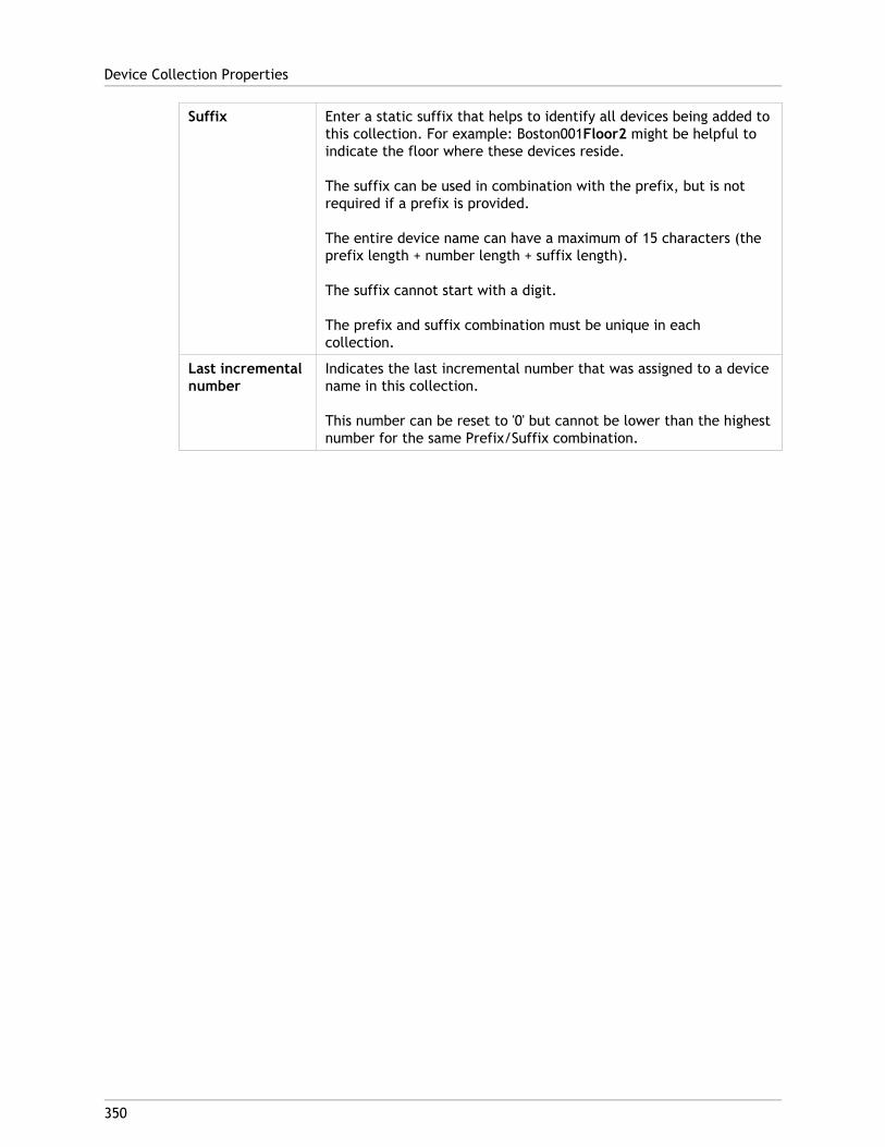
Suffix Enter a static suffix that helps to identify all devices being added tothis collection. For example: Boston001Floor2 might be helpful toindicate the floor where these devices reside.
The suffix can be used in combination with the prefix, but is notrequired if a prefix is provided.
The entire device name can have a maximum of 15 characters (theprefix length + number length + suffix length).
The suffix cannot start with a digit.
The prefix and suffix combination must be unique in eachcollection.
Last incrementalnumber
Indicates the last incremental number that was assigned to a devicename in this collection.
This number can be reset to '0' but cannot be lower than the highestnumber for the same Prefix/Suffix combination.
Device Collection Properties
350
351
Device Collection Management Tasks
To manage device collections, select from the following tasks:
● Creating a Device Collection
● Importing Target Devices into Collections
● Deleting Collections
● Refresh
● Boot Target Devices in a Collection
● Restart Target Devices in a Collection
● Shutdown Target Devices in a Collection
● Send Messages to Target Devices in a Collection
● Move Collections
● Accessing Audit Information for a collection
● Activating Microsoft MAK licensing for target devices within a collection
352
Creating a Device Collection
To create a new device collection:
1. In the Console, right-click on the Device Collections folder where the new collectionwill exist, then select the Create device collection menu option. The Device CollectionProperties dialog appears.
2. On the General tab, type a name for this new device collection in the Name text box,and a description of this collection in the Description text box, then click the Securitytab.
3. Under the Device Administrators list, click Add. The Add Security Group dialogappears.
4. To assign a group with the Device Administrator role, type or select the appropriatedomain and group name in the text box, then click OK.
5. Optionally, repeat steps 2 and 3 to continue assigning groups as device administrators.
6. Under the Device Operators list, click Add. The Add Security Group dialog appears.
7. To assign a group with the Device Operator role, type or select the appropriate domainand group name in the text box, then click OK.
8. Optionally, repeat steps 2 and 3 to continue assigning groups as device operators.
9. Click OK to close the dialog box.
353
Importing Target Devices into a Collection
The Import Target Devices Wizard allows you to import target device information from afile. The target device information must first be saved as a .csv file, it can then beimported into a device collection.
Note: The .csv text file can be created with a .txt file, NotePad.exe or Excel. Itcontains one line per target device, which is formatted as follows:
DeviceName,MAC-Address,SiteName,CollectionName,Description
where DeviceName=Name of new target device and MAC-Address= MAC address of newdevice; such as 001122334455, 00-11-22-33-44-55, or 00:11:22:33:44:55.The wizard can be accessed from the farm, site, and device collection right-click menus. Ifaccessed from the site or collection, only those target devices in the import file that matchthe site and collection by name, will be included in the import list.
The wizard also provides the option to automatically create the site or collection using theinformation in the file, if either does not already exist. There is also the option to use thedefault collection’s device template, if it exists for that collection.
A log file is generated with an audit trail of the import actions. The file is located in:
C:\Documents and Settings\All Users\Application Data\Citrix\Provisioning Services\log
To Import target devices into a Collection:
1. In the Console, right-click on the device collection that the target devices should beimported to, then click Target Device>Import devices. The Import Target DevicesWizard displays.
2. Type or browse for the file to import. The target device information is read from thefile and displays in the table below. Information can include the target device name,MAC address, and optionally description.
3. Highlight one or more target devices to import. If applying the collection template tothe imported target devices, select the Apply collection template device whencreating devices checkbox.
4. Click Import to import the .csv text file containing target device information, into theselected collection. The status column indicates if the import was successful.
354
Deleting a Collection
Deleting a collection deletes any target device member records within the collection. Therecords can be recreated by manually adding them or using the Auto-add feature.
Note: Deleting a target device also deletes that device from any views that it wasassociated with.
If target devices are members of collections within the same site, the members of onecollection can be dragged and dropped to other collections, then the original collection canbe deleted. If a device collection needs to be moved to a different site or that site becomesobsolete, you can use the export and import features to add the devices to a collection inanother site, then the original collection can be deleted.
To delete a collection:
1. In the Console tree, right-click on the collection folder that you want to delete, thenselect the Delete menu option. A confirmation message appears.
2. Click OK to delete this collection. The collection no longer displays in the Console tree.

355
Refreshing a Collection in the Console
After making changes to a collection, it may be necessary to refresh the collection beforethose changes appear in the Console. To refresh, right-click on the collection in the tree,then select the Refresh menu option.
356
Booting Target Devices within aCollection
To boot target devices within a collection:
1. Right-click on the collection in the Console tree, then select the Target Device>Bootmenu option. The Target Device Control dialog displays with the Boot devices menuoption selected in the Settings drop-down menu. Target devices display in the Devicetable.
2. Click the Boot devices button to boot target devices. The Status column displays theBoot Signal status until the target device successfully receives the signal, then statuschanges to success.
357
Restarting Target Devices within aCollection
To restart target devices within a collection:
1. Right-click on the collection in the Console tree, then select the Target Device>Restartdevices menu option. The Target Device Control dialog displays with the Restartdevices menu option selected in the Settings drop-down menu. Devices display in theDevice table.
2. Type the number of seconds to wait before restarting target devices in the Delay textbox.
3. Type a message to display on target devices in the Message text box.
4. Click the Restart devices button to restart target devices. The Status column displaysthe restart signal status until the target device successfully receives the signal, thenstatus changes to Success.
358
Shutdown Target Devices within aCollection
To shutdown target devices members within a collection
1. Right-click on the collection in the Console tree, then select the TargetDevice>Shutdown devices menu option. The Target Device Control dialog displays withthe Shutdown devices menu option selected in the Settings drop-down menu. Targetdevices display in the Device table.
2. Type the number of seconds to wait before shutting down target devices in the Delaytext box. Type a message to display on target devices in the Message text box.
3. Click the Shutdown devices button to shutdown target devices. The Status columndisplays the shutdown signal status until the target device shuts down. As each targetdevice successfully shuts down, the status changes to Success.
359
Sending Messages to Target Deviceswithin a Collection
To send a message to target device members within a collection
1. Right-click on the collection in the Console tree, then select the Target Device>Sendmessage menu option. The Target Device Control dialog displays with the Message todevices menu option selected in the Settings drop-down menu. Target devices display inthe Device table.
2. Type a message to display on target devices in the Message text box.
3. Click the Send message button. The Status column displays the message signal statusuntil the target device successfully receives the message, then the status changes toSuccess.
360
Moving Collections within a Site
Target devices can be moved from one collection to another collection within the samesite.
To move a collection:
1. In the Console, expand the collection, right-click on the target device, then select theMove menu option.
2. From the drop-down menu, select the collection to move this target device into, thenclick OK to close the dialog.
361
Configuring Microsoft KMS VolumeLicensing
Microsoft provides two mechanisms for administering volume licenses. This sectiondescribes use of the Key Management Server (KMS) license keys with Provisioning Services toapply volume licenses for Microsoft Server 2008, Windows 7 and Vista, as well as Office2010.
Note: To support KMS licensing, the Soap Server user account must have the 'Performvolume maintenance tasks' (SeManageVolumePrivilege) privilege.
KMS volume licensing utilizes a centralized activation server that runs in the datacenter,and serves as a local activation point (opposed to having each system activate withMicrosoft over the internet).
Note: When preparing or updating a KMS configured vDisk that will be copied or cloned, itis important to complete the final KMS configuration task, which is to change the vDiskmode from Private Image Mode to Shared Image Mode, before copying or cloning thevDisk to other Provisioning Servers. Also, both the .pvp and .vhd file must be copied toretain the properties and KMS configuration of the original vDisk.
The tasks involved in configuring a vDisk image to use KMS volume licensing and managingthat vDisk in a Provisioning Services farm include:
● Enabling KMS licensing on the vDisk being created. This is accomplished by selecting theKMS menu option on the Microsoft Volume Licensing tab when running the ImagingWizard (refer to Imaging Wizard for details).
● Preparing the new base vDisk image
● Maintaining or upgrading the vDisk image
Note: If KMS licensing was not configured on the vDisk when the Imaging Wizard was run,it can alternatively be configured using the Console user interface (refer to the MicrosoftVolume Licensing tab, or the MCLI and PowerShell command-line interfaces (refer to theMCLI or PowerShell Programmers Guide for details).
Preparing the New Base vDisk Image for KMS VolumeLicensing
After a vDisk is created using the Imaging Wizard, it must be reset to a non-activated stateusing the rearm command.
It is important to perform this operation on a system booted from the vDisk in Private ImageMode so that the master target device hard disk's rearm count is not reduced.

Note: Microsoft limits the number of times you can run rearm on an installed OS image.The operating system will need to be reinstalled if the number of allowed rearm attemptsis exceeded.
1. Boot the target device from the vDisk in Private Image Mode to rearm.
● For Windows Vista, 7, 2008, and 2008R2 run: cscript.exe slmgr.vbs -rearm
● For Office 2010 (for 64bit client): Program Files(x86)\Common Files\microsoftshared\OfficeSoftwareProtectionPlatform\OSPPREARM.EXE
● For Office 2010 (for 32bit client): Program Files(x32)\Common Files\microsoftshared\OfficeSoftwareProtectionPlatform\OSPPREARM.EXE
2. A message will prompted you to reboot the system, DO NOT REBOOT. Instead shut downthe Target device.
3. Set the vDisk mode to Standard Image mode.
4. Stream the vDisk to one or more target devices.
Maintaining or Upgrading a vDisk Image that UsesKMS Volume Licensing
To maintain or upgrade a vDisk image that is configured to use KMS volume licensing:
1. Set the vDisk mode to Private Image mode.
2. Stream the vDisk to a target device.
3. Apply the OS/application service pack/update, then shutdown the target device.
4. Set the vDisk mode back to Shared Image mode.
5. Stream the vDisk to the target device in Shared Image mode.
Note: If Office 2010 is installed as vDisk update, or after vDisk has gone through basedisk preparation once, then the base disk preparation needs to be repeated asfollows:
a. In the Console, right-click on the vDisk, then select the File Properties menuoption. The vDisk File Properties dialog appears.
b. Click on the Microsoft Volume Licensing tab, then change the licensing option fromKMS to None.
c. On the Mode tab, set the vDisk access mode to Private Image mode.
d. PXE boot to the vDisk in Private Image mode to rearm:
● For Windows Vista, 7, 2008, and 2008R2 run: cscript.exe slmgr.vbs -rearm
Configuring Microsoft KMS Volume Licensing
362

● For Office 2010 (for 64bit client): Program Files(x86)\Common Files\microsoftshared\OfficeSoftwareProtectionPlatform\OSPPREARM.EXE
● For Office 2010 (for 32bit client): Program Files(x32)\Common Files\microsoftshared\OfficeSoftwareProtectionPlatform\OSPPREARM.EXE
e. A message will prompted you to reboot the system, DO NOT REBOOT. Instead shutdown the Target device.
f. In the Console, right-click on the vDisk, then select the File Properties menuoption. The vDisk Properties dialog appears.
g. Click on the Microsoft Volume Licensing tab, then change the license option fromNone to KMS.
h. On the Mode tab, set the vDisk access mode to Shared Image mode.
i. Stream the vDisk to the target devices.
Configuring Microsoft KMS Volume Licensing
363
364
Configuring Microsoft MAK VolumeLicensing
Microsoft provides two mechanisms for administering volume licenses. This sectiondescribes the use of Multiple Activation Keys (MAKs). A MAK corresponds to a certainnumber of purchased OS licenses. The MAK is entered during the installation of the OS oneach system, which activates the OS and decrements the count of purchased licensescentrally with Microsoft. Alternatively, a process of 'proxy activation' is done using theVolume Activation Management Toolkit (VAMT). This allows activation of systems that donot have network access to the internet. Provisioning Services leverages this proxyactivation mechanism for Standard Image mode vDisks that have MAK licensing modeselected when the vDisk is created.
Note: In order for MAK licensing to work, the Volume Activation Management Tool (VAMT)must be installed on all Provisioning Servers within a farm. This tool is available fromhttp://www.microsoft.com/downloads/en/details.aspx?FamilyID=ec7156d2-2864-49ee-bfcb-777b898ad582&displaylang=en.
MAK licensing tasks include:
● Setting the vDisk's licensing mode
● Entering MAK User Credentials
● Activating target devices that use MAK enabled vDisks
● Maintaining MAK Activations
Setting the vDisk's licensing mode
A vDisk can be configured to use Microsoft Multiple Activation Key (MAK) licensing when theImaging Wizard is run (refer to Imaging Wizard). If MAK licensing was not configured whenthe Imaging Wizard was run, the vDisk's licensing mode property can be set using theConsole, MCLI, or PowerShell user interface. The licensing mode should be set beforeattempting to activate target devices.
Note: For information on using the command-line interfaces, refer to the MCLI orPowerShell Programmers Guide.
Entering MAK User Credentials
Before target devices that use MAK enabled vDisks can be activated, MAK user credentialsmust be entered for a site.
Note: The user must have administrator rights on all target devices that use MAK enabledvDisks and on all Provisioning Servers that will stream the vDisks to target devices.
To enter credentials:

1. Right-click on the site where the target devices exist, then select the Properties menuoption.
2. On the MAK tab, enter the user and password information in the appropriate text boxes,then click OK.
Activating target devices that use MAK enabled vDisks
After a vDisk is configured for MAK volume licensing and user credentials have beenentered, each booted target device that uses the vDisk needs to be activated with a MAK.
Note: After all licenses for a given MAK have been used, a new key will be required inorder to allow additional target devices that share this vDisk image to be activated.
To activate target devices that use MAK volume licensing from the Console:
1. Boot all target devices that are to be activated.
2. In the Console, right-click on the collection or view that includes target devices thatrequire MAK license activation, then select the Manage MAK Activations... menuoption. The Manage MAK Activations dialog appears.
3. In the Multiple activation key text box, enter the MAK to be used to activate the targetdevices.
4. The number of booted target devices that require activation, display on the dialog.From the list of booted devices, check the box next to each target device that shouldbe activated.
5. Click OK to activate licensing for all selected target devices (do not close the dialoguntil the activation process is completed. The process can be stopped by clicking theCancel button. Closing the dialog before the activation process completes stops theprocess and may result in some target devices not being activated). The Status columnindicates if a target device is currently being activated (Activating) or the activationfailed (Failed). If all target devices were activated successfully, click OK to close thedialog. After the activation process completes, if one or more target devices were notselected to be activated, or if devices were not activated successfully, the dialogdisplays listing any unactivated devices. After resolving any issues, repeat this step toactivate the remaining target devices.
Note: The Manage MAK Activations... option does not display after all currentlybooted target devices have been successfully activated.
Maintaining MAK Activations
When a target device has a MAK activated vDisk assigned, unassigning it removes anysaved MAK reactivation information. If the vDisk is reassigned in the future, the targetdevice will not reactivate. To prevent the loss of MAK activation, do not unassign theactivated disk from the target device.
To change a target device's vDisk, without losing the MAK activation, select one of thefollowing methods:
a. Assign more than one vDisk to the target device and set the default accordingly.
Configuring Microsoft MAK Volume Licensing
365
b. Assign additional vDisks to the target device and temporarily disable the MAKactivated vDisk.
To update a MAK activated vDisk, the AutoUpdate feature must be used so that the MAKactivation information, required for shared device reactivation, is maintained.
Additional MAK considerations:
● Use of manual vDisk updates (unassigning one vDisk and reassigning another vDisk)will result in the loss of the required MAK activation information and will require anew activation, which would consume another license.
● Use of AutoUpdate to deploy a new vDisk, from a different OS install than theprevious vDisk, will result in mismatched MAK activation information. In this case, anew activation must be performed from the command line interface, as onlyunactivated target devices can be activated from the MMC console.
Configuring Microsoft MAK Volume Licensing
366
367
Managing Views
The Console’s Views feature provides a method that allows you to quickly manage a groupof devices. Views are typically created according to business needs. For example, a viewcan represent a physical location, such as a building or user type. Unlike device collections,a target device can be a member of any number of views.
Farm administrators can create and manage views in the Console tree’s Farm>Views folder.Farm views can include any target device that exists in this farm. Site administrators cancreate and manage views in the Console tree’s Farm>Sites>YourSite>Views folder. Siteviews can only include target devices that exist within that site (YourSite).
To display or edit a views properties, right-click on an existing view in the Console, thenselect the Properties menu option. The View Properties dialog displays and allows you toview or make modifications to that view.
To perform actions on all members of a view, such as rebooting all target devices membersin this view, refer to Configuring Views in the Console.
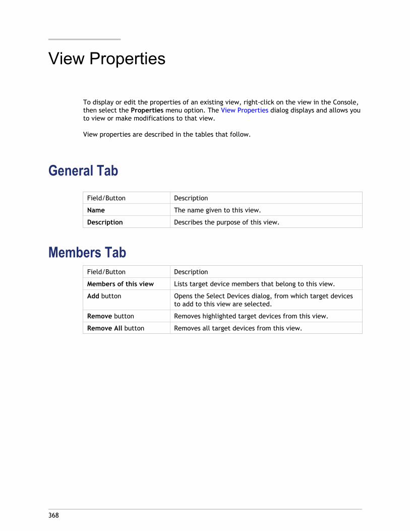
368
View Properties
To display or edit the properties of an existing view, right-click on the view in the Console,then select the Properties menu option. The View Properties dialog displays and allows youto view or make modifications to that view.
View properties are described in the tables that follow.
General TabField/Button Description
Name The name given to this view.
Description Describes the purpose of this view.
Members TabField/Button Description
Members of this view Lists target device members that belong to this view.
Add button Opens the Select Devices dialog, from which target devicesto add to this view are selected.
Remove button Removes highlighted target devices from this view.
Remove All button Removes all target devices from this view.
369
Managing Views in the Console
To manage views, select from the following actions:
● Creating a View
● Pasting Device Properties
● Deleting a View
● Refreshing a View
● Booting Devices within a View
● Restarting Devices within a View
● Shutdown Devices within a View
● Sending Messages to Target Devices within a View
● Configuring Microsoft KMS Volume Licensing
● Activating Microsoft MAK licensing to Target Devices within a View
● Active Directory; to use the Views feature with the Active Directory Managementfeature, refer to Managing Domain Computer Accounts.
Creating a View1. In the Console, right-click on the Views folder where the new view will exist, then
select the Create view menu option. The View Properties dialog appears.
2. On the General tab, type a name for this new view in the Name text box and adescription of this view in the Description text box, then click the Members tab.
3. Click the Add button to add new target device members to this view. The SelectDevices dialog appears.
4. From the drop-down menus, select the site, then the device collection that you want toadd target device(s) from. All members of that device collection appear in the list ofavailable target devices.
5. Highlight one of more target devices in this collection, then click Add to add them tothe new view. To add additional target devices from other device collections, repeatsteps 4 and 5.
6. Click OK to close the dialog. All selected target devices now display on the Memberstab.
Pasting Device PropertiesTo copy the properties of one target device, and paste those properties to target devicemembers within a view, complete the steps that follow.
To paste device properties to members in a view:
1. In the Console’s details pane, right-click on the target device that you want to copyproperties from, then select Copy device properties. The Copy Device Propertiesdialog appears.
2. Select the checkbox next to the properties that you want to copy, then click Copy. Theproperties are copied to the clipboard and the dialog closes.
3. Right-click on the view containing the target devices that will inherit the copiedproperties, then select the Paste device properties menu option. The Paste DeviceProperties dialog appears displaying the name and properties of the target device thatwere copied.
4. Under the Paste to... table heading, highlight the target devices that will inherit theseproperties, then click Paste.
5. Click Close to close the dialog.
Deleting a ViewIf a view becomes obsolete, you can delete the view. Deleting a view does not delete thetarget device from the collection.
1. In the Console’s tree, right-click on the view folder that you want to delete, then selectthe Delete menu option. A confirmation message appears.
2. Click OK to delete this view. The view no longer displays in the Console tree.
Refreshing a ViewAfter making changes to a view, it may be necessary to refresh the view before thosechanges appear in the Console. To refresh the view, right-click on the view in the tree,then select the Refresh menu option.
Booting Devices within a View1. Right-click on the view in the Console tree, then select the Boot devices menu option.
The Target Device Control dialog displays with the Boot devices menu option selected in
Managing Views in the Console
370
the Settings drop-down menu. By default, all devices are highlighted in the Devicetable.
2. Click the Boot devices button to boot target devices. The Status column displays theBoot Signal status until the target device boots. As each target device successfullyboots, the status changes to Success.
Restarting Devices within a View1. Right-click on the view in the Console tree, then select the Restart devices menu
option. The Target Device Control dialog displays with the Restart devices menu optionselected in the Settings drop-down menu. By default, all devices are highlighted in theDevice table.
2. Type the number of seconds to wait before restarting target devices in the Delay textbox.
3. Type a message to display on target devices in the Message text box.
4. Click the Restart devices button to restart target devices. The Status column displaysthe Restart Signal status until the target device restarts. As each target devicesuccessfully restarts, the status changes to Success.
Shutdown Devices within a View1. Right-click on the view in the Console tree, then select the Shutdown devices menu
option. The Target Device Control dialog displays with the Shutdown devices menuoption selected in the Settings drop-down menu. By default, all devices are highlightedin the Device table.
2. Type the number of seconds to wait before shutting down target devices in the Delaytext box.
3. Type a message to display on target devices in the Message text box.
4. Click the Shutdown devices button to shutdown target devices. The Status columndisplays the Shutdown Signal status until the target device shuts down. As each targetdevice successfully shuts down, the status changes to Success.
Sending Messages to Target Devices within a ViewTo send a message to target devices members within a view:
1. Right-click on the view in the Console tree, then select the Send message menu option. The Target Device Control dialog displays with the Message to devices menu option
Managing Views in the Console
371

selected in the Settings drop-down menu. By default, all devices are highlighted in theDevice table.
2. Type a message to display on target devices in the Message text box.
3. Click the Send message button. The Status column displays the Message Signal statusuntil target devices receive the message. As each target device successfully receivesthe message, the status changes to Success.
Managing Views in the Console
372
373
Managing for Highly AvailableImplementations
The key to establishing any highly available network is to identify the critical components,create redundancy for these components, and ensure automatic failover to the secondarycomponent in the event that the active component fails. Critical components include:
● Database
● Provisioning Servers
● vDisks and storage
Provisioning Services provides several options to consider when configuring for a highlyavailable implementation, including:
● Database
● Offline Database Support, allows Provisioning Servers to use a snapshot of thedatabase if the connection to the database is lost.
● Database Mirroring, support for database mirroring.● Provisioning Servers
● Provisioning Server Failover, should a server become unavailable for any reason,another server within the site can provide active target devices with the vDisk.
● Managing Load Balancing Across Servers, provides load balancing betweenProvisioning Servers to prevent overload, while allowing for server capacity to beused more effective and efficiently.
● vDisks and Storage
● vDisk Replication, supports the replication of vDisks on stores that are local(local/attached storage on Provisioning Servers), as well as replication of vDisksacross multiple sites that use shared storage.
● Configuring Highly Available Shared Storage, supports various shared-storageconfigurations.
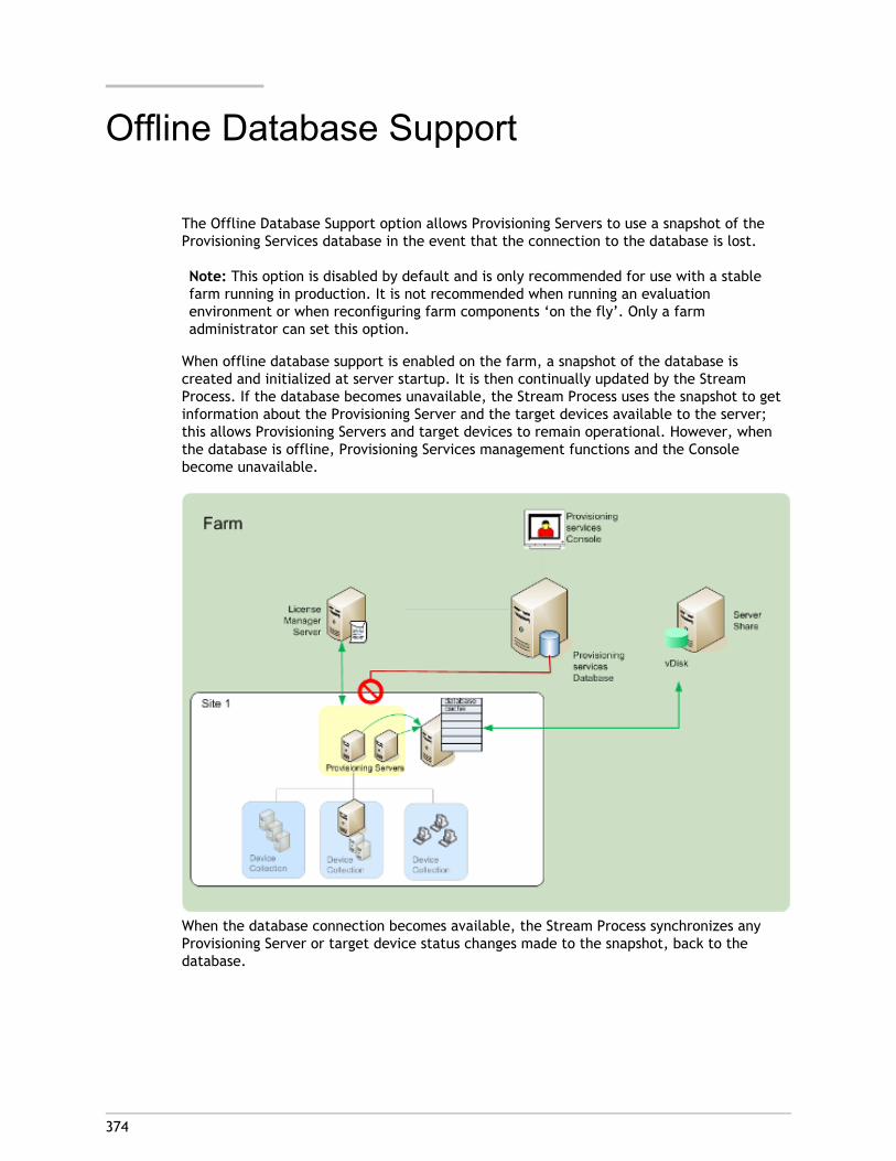
374
Offline Database Support
The Offline Database Support option allows Provisioning Servers to use a snapshot of theProvisioning Services database in the event that the connection to the database is lost.
Note: This option is disabled by default and is only recommended for use with a stablefarm running in production. It is not recommended when running an evaluationenvironment or when reconfiguring farm components ‘on the fly’. Only a farmadministrator can set this option.
When offline database support is enabled on the farm, a snapshot of the database iscreated and initialized at server startup. It is then continually updated by the StreamProcess. If the database becomes unavailable, the Stream Process uses the snapshot to getinformation about the Provisioning Server and the target devices available to the server;this allows Provisioning Servers and target devices to remain operational. However, whenthe database is offline, Provisioning Services management functions and the Consolebecome unavailable.
When the database connection becomes available, the Stream Process synchronizes anyProvisioning Server or target device status changes made to the snapshot, back to thedatabase.
ConsiderationsThe following features, options, and processes remain unavailable when the databaseconnection is lost, regardless if the Offline Database Support option is enabled:
● AutoAdd target devices
● vDisk updates
● vDisk creation
● Active Directory password changes
● Stream Process startup
● Image Update service
● Management functions; PowerShell, MCLI, SoapServer and the Console
Enabling Offline Database SupportTo enable the Offline Database Support option
1. In the Console tree, right-click on the Farm, then select Properties. The FarmProperties dialog appears.
2. On the Options tab, check the checkbox next to Offline Database Support.
3. Restart Stream services.
Offline Database Support
375
376
Database Mirroring
In order to provide a highly available configuration, if you mirror a MS SQL database and theprimary version becomes unavailable, Provisioning Services supports the mirrored version.This results in improved overall availability of Provisioning Services.
Database mirroring can be implemented in a new or existing farm and requires thefollowing high-level tasks:
● Creating the Provisioning Services MS SQL primary database (created when theInstallation Wizard is run on the server)
Note: For database mirroring to function, the recovery model must be set to Full.
● Identifying the primary database server and instance (identified when the ConfigurationWizard is run)
● Identifying an existing MS SQL failover database server (identified, not created, whenthe Configuration Wizard is run)
● Configuring mirroring between the primary and failover database servers (configuredusing MS SQL database server tools)
Note: Citrix recommends that the failover server be up and running before enablingdatabase mirroring in the farm. For helpful information on configuring the MS SQLfailover server, refer tohttp://technet.microsoft.com/en-us/library/ms188712.aspx.
To implement and manage mirroring within a Provisioning Services farm, choose from thefollowing:
● Enabling Mirroring When Configuring a New Farm
● Enabling Mirroring Within an Existing Farm
Note: The procedures that follow are only intended to call out the steps that areapplicable to database mirroring when running the Configuration Wizard.
Note: Run the Configuration Wizard to specify the new failover sever so that the status ofthe Provisioning Service's farm correctly reports the new settings. After re-running thewizard, some services, including the stream service, restart so that the farm has the newfailover server settings specified with the wizard was run.
Enabling Mirroring when Configuring a New FarmTo enable mirroring:
1. Start the Configuration Wizard on a server that will be in the new farm.
2. While running the wizard, when the Farm Configuration page displays, select theCreate Farm radio button to create a new farm, then click Next.
3. Type or use the Browse button to identify the primary database server and instancenames. Optionally, enter a TCP port number to use to communicate with this databaseserver.
4. Enable the Specify database mirror failover partner option.
5. Type or use the Browse button to identify the failover database server and instancenames. Optionally, enter a TCP port number to use to communicate with this server.
6. Click Next. If the failover database has already been configured and it is up andrunning, Provisioning Services should be able to connect to it. If the failover databaseserver has not yet been created or is not running, an error message may displayindicating a failure to connect. In this case, when prompted, click Yes to continue (thefailover database can be created and configured after the new farm is created).
7. On the New Farm page, enter a name for the new database on the primary databaseserver, then complete any additional requested information.
8. Click Next.
9. Complete the remaining wizard pages.
Enabling Mirroring Within an Existing FarmTo enable mirroring within an existing farm:
1. Confirm that the primary and failover database servers are up and running.
2. Using MS SQL server tools, mirror the Provisioning Services database to a database onthe failover database server.
3. Run the Configuration Wizard on each server.
4. Identify the farm by choosing either the Farm is already configured or the Joinexisiting farm option on the Farm Configuration page.
5. On the Database Server page, select the primary and failover database servers andinstance names, then enable the database mirror failover feature .
6. Complete the remaining wizard pages.
Database Mirroring
377
378
Provisioning Server Failover
By default, all Provisioning Servers within a site that can access a vDisk can provide thatvDisk to target devices. Multiple Provisioning Servers can access the same physical fileslocated on shared storage, which allows a target device to establish a connection on analternate Provisioning Server if the connection to the active Provisioning Server isinterrupted for any reason. A target device does not experience any disruption in service orloss of data when failover occurs.
Note: For implementations that use vDisk replication, if a server failover occurs, onlythose servers with access to an identical replicated vDisk can provide that vDisk to targetdevices. For example; if vDisk is replicated across three servers hard drives and then oneof the vDisks is updated, that vDisk is no longer identical and will not be considered if aserver failover occurs. Even if the same exact update is made to two of the vDisks, thetimestamps on each will differ, therefore the vDisks are no longer identical.
Note: Provisioning Services does not support the high availability of vDisks on localstorage that are in Private Image mode or that are currently in maintenance (read/writeenabled).
If load balancing is enabled for the vDisk and a server providing that vDisk should fail,Provisioning Services automatically balances the target device load between the remainingservers. If the load balancing option is not enabled, a single server is assigned to providethe vDisk to target devices, therefore failover will not occur.
Note: For information on configuring Provisioning Services to automatically balance thetarget device load between servers, refer to Balancing the Target Device Load onProvisioning Servers.
Figure 1. Basic High Availability Implementation
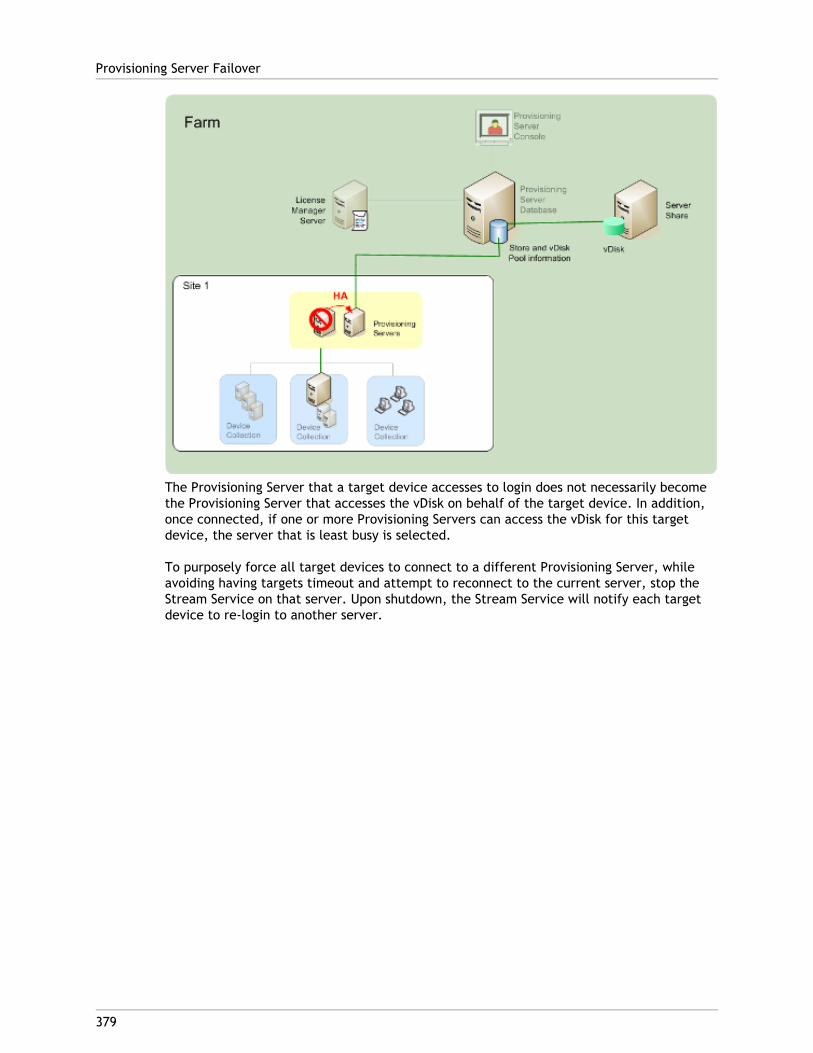
The Provisioning Server that a target device accesses to login does not necessarily becomethe Provisioning Server that accesses the vDisk on behalf of the target device. In addition,once connected, if one or more Provisioning Servers can access the vDisk for this targetdevice, the server that is least busy is selected.
To purposely force all target devices to connect to a different Provisioning Server, whileavoiding having targets timeout and attempt to reconnect to the current server, stop theStream Service on that server. Upon shutdown, the Stream Service will notify each targetdevice to re-login to another server.
Provisioning Server Failover
379
380
Testing Target Device Failover
To ensure that devices can failover successfully, complete the following:
1. Double-click the vDisk status icon on the target device and then note the IP address ofthe connected Provisioning Server.
2. Right-click the connected Provisioning Server in the Console. Select Stream Services,then select Stop.
3. Confirm that the IP address of the connected Provisioning Server changes to that of analternate Provisioning Server in the vDisk status dialog on the target device.
381
Configuring for High Availability withShared Storage
Provisioning Servers are configured to access your shared-storage location. ProvisioningServices supports various shared-storage configurations. The steps for configuring for highlyavailable storage in the network varies depending on shared-storage configurations.
Note: Installing Provisioning Services affects the following registrykey:HKEY_LOCAL_MACHINE\System\CurrentControlSet\Services\MRXSmb\Parameters\OplocksDisabled.Changing this registry key disables Windows Opportunity Locking, providing the fastestpossible failover time when contact with the active Provisioning Server is lost. Withoutthis change, failover times can take up to one minute. During this time, Windows doesnot allow access to the vDisk file that was in use by the failed Provisioning Server. Bydisabling Windows Opportunity Locking on Provisioning Servers, the Stream Service canhave immediate access to vDisk files. However, this reduces caching of remote vDisk datafor the entire Provisioning Server.
Windows Shared-Storage ConfigurationNote: The instructions below provide the procedures on a Windows XP operating system.If you are using another operating system, the dialogs may appear slightly different, andslightly different steps may be required. The concepts are the same regardless ofoperating system. See your operating system’s online help for more information.
Stream Services run under a user account; Service account credentials. If you are using aWindows shared-storage location, the Service account credentials (user account name andpassword) must be a domain account that is configured on each Provisioning Server, inorder to access the Stream Service and the shared storage system.
Configuring Service Account Credentials for Provisioning Servers includes the followinghigh-level tasks:
● Creating Service account credentials on the domain controller
● Assigning Service account credentials to the Services
● Configuring HA Storage Access
Creating Stream-Service Account Credentials on theDomain Controller
The Stream Service runs under the user account. When the Stream Service accesses a vDiskstored locally on the Provisioning Server, the local user rights provide full access. However,when the database or vDisk is located on a remote storage device, the Streaming Servermust use a domain account with rights to both the Provisioning Server and the remotestorage location. An administrator must assign full control rights to the Stream Serviceaccount in order for it to read and write to the remote storage location.
An administrator creates service account credentials in Active Directory and assigns thecredentials to the Stream Service on all Provisioning Servers that will participate in HA.Alternatively, an existing domain user account can be given full control rights to thenetwork share and be assigned to the Stream Service.
Note: Your Microsoft Windows online help contains detailed instructions for creating bothlocal and domain accounts.
Consider the following when creating service account credentials:
● You must be logged on as an administrator or a member of the Administrator group tocreate a domain account.
● Clear the ‘User must change password at next logon’ checkbox.
Assigning Stream-Service Account CredentialsManually
When running the Configuration Wizard on a Provisioning Server, you are prompted to enteran account name and password for the Stream Service to use. This account must haveaccess permissions for any stores it is given access to, as well as permissions in SQL Serverfor database access. If necessary, credentials can be assigned manually.
To assign the Service account credentials to the Stream Service:
1. Open the Windows Control Panel.
2. Go to Administrative Tools>Services.
3. Double-click on the first PVS Stream Service name in the Services list.
4. On the Log On tab, select This Account, then click Browse.
5. Click Locations, select the domain node, then click OK.
6. Type the name of the Stream Service user account, then click Check Names.
7. Click OK to close the Select User dialog.
8. On the Log On tab, enter and confirm the Stream Service account password, then clickOK.
Configuring for High Availability with Shared Storage
382
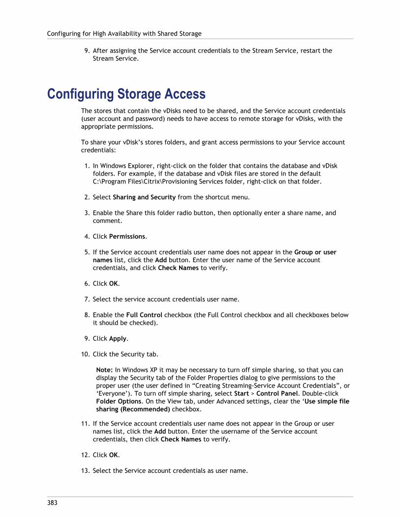
9. After assigning the Service account credentials to the Stream Service, restart theStream Service.
Configuring Storage AccessThe stores that contain the vDisks need to be shared, and the Service account credentials(user account and password) needs to have access to remote storage for vDisks, with theappropriate permissions.
To share your vDisk’s stores folders, and grant access permissions to your Service accountcredentials:
1. In Windows Explorer, right-click on the folder that contains the database and vDiskfolders. For example, if the database and vDisk files are stored in the defaultC:\Program Files\Citrix\Provisioning Services folder, right-click on that folder.
2. Select Sharing and Security from the shortcut menu.
3. Enable the Share this folder radio button, then optionally enter a share name, andcomment.
4. Click Permissions.
5. If the Service account credentials user name does not appear in the Group or usernames list, click the Add button. Enter the user name of the Service accountcredentials, and click Check Names to verify.
6. Click OK.
7. Select the service account credentials user name.
8. Enable the Full Control checkbox (the Full Control checkbox and all checkboxes belowit should be checked).
9. Click Apply.
10. Click the Security tab.
Note: In Windows XP it may be necessary to turn off simple sharing, so that you candisplay the Security tab of the Folder Properties dialog to give permissions to theproper user (the user defined in “Creating Streaming-Service Account Credentials”, or‘Everyone’). To turn off simple sharing, select Start > Control Panel. Double-clickFolder Options. On the View tab, under Advanced settings, clear the ‘Use simple filesharing (Recommended) checkbox.
11. If the Service account credentials user name does not appear in the Group or usernames list, click the Add button. Enter the username of the Service accountcredentials, then click Check Names to verify.
12. Click OK.
13. Select the Service account credentials as user name.
Configuring for High Availability with Shared Storage
383
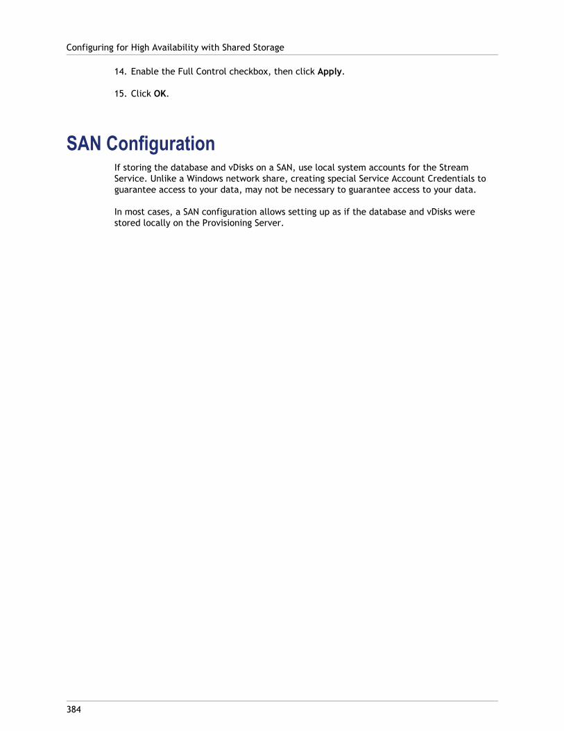
14. Enable the Full Control checkbox, then click Apply.
15. Click OK.
SAN ConfigurationIf storing the database and vDisks on a SAN, use local system accounts for the StreamService. Unlike a Windows network share, creating special Service Account Credentials toguarantee access to your data, may not be necessary to guarantee access to your data.
In most cases, a SAN configuration allows setting up as if the database and vDisks werestored locally on the Provisioning Server.
Configuring for High Availability with Shared Storage
384
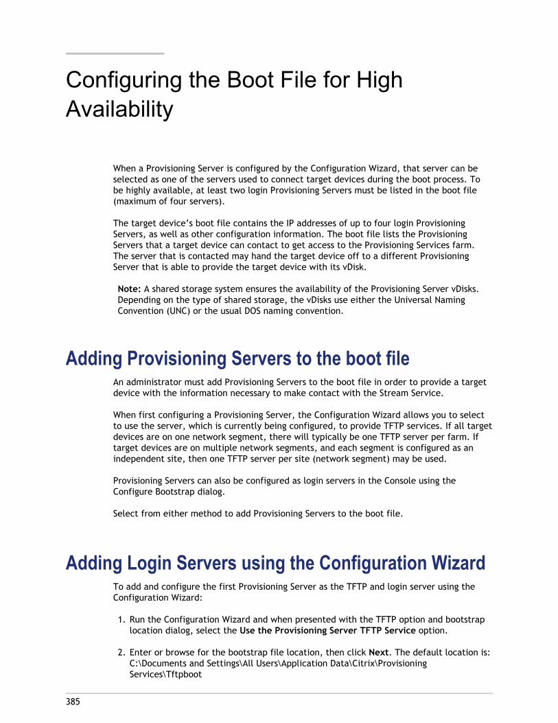
385
Configuring the Boot File for HighAvailability
When a Provisioning Server is configured by the Configuration Wizard, that server can beselected as one of the servers used to connect target devices during the boot process. Tobe highly available, at least two login Provisioning Servers must be listed in the boot file(maximum of four servers).
The target device’s boot file contains the IP addresses of up to four login ProvisioningServers, as well as other configuration information. The boot file lists the ProvisioningServers that a target device can contact to get access to the Provisioning Services farm.The server that is contacted may hand the target device off to a different ProvisioningServer that is able to provide the target device with its vDisk.
Note: A shared storage system ensures the availability of the Provisioning Server vDisks.Depending on the type of shared storage, the vDisks use either the Universal NamingConvention (UNC) or the usual DOS naming convention.
Adding Provisioning Servers to the boot fileAn administrator must add Provisioning Servers to the boot file in order to provide a targetdevice with the information necessary to make contact with the Stream Service.
When first configuring a Provisioning Server, the Configuration Wizard allows you to selectto use the server, which is currently being configured, to provide TFTP services. If all targetdevices are on one network segment, there will typically be one TFTP server per farm. Iftarget devices are on multiple network segments, and each segment is configured as anindependent site, then one TFTP server per site (network segment) may be used.
Provisioning Servers can also be configured as login servers in the Console using theConfigure Bootstrap dialog.
Select from either method to add Provisioning Servers to the boot file.
Adding Login Servers using the Configuration WizardTo add and configure the first Provisioning Server as the TFTP and login server using theConfiguration Wizard:
1. Run the Configuration Wizard and when presented with the TFTP option and bootstraplocation dialog, select the Use the Provisioning Server TFTP Service option.
2. Enter or browse for the bootstrap file location, then click Next. The default location is:C:\Documents and Settings\All Users\Application Data\Citrix\ProvisioningServices\Tftpboot
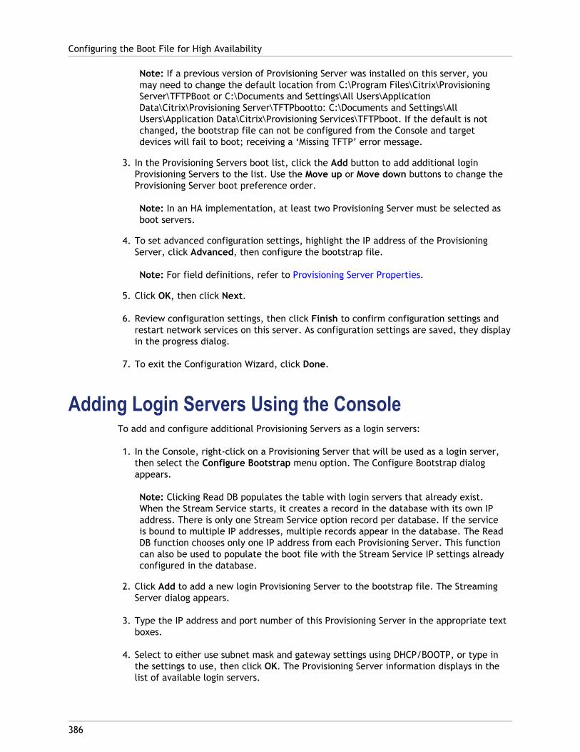
Note: If a previous version of Provisioning Server was installed on this server, youmay need to change the default location from C:\Program Files\Citrix\ProvisioningServer\TFTPBoot or C:\Documents and Settings\All Users\ApplicationData\Citrix\Provisioning Server\TFTPbootto: C:\Documents and Settings\AllUsers\Application Data\Citrix\Provisioning Services\TFTPboot. If the default is notchanged, the bootstrap file can not be configured from the Console and targetdevices will fail to boot; receiving a ‘Missing TFTP’ error message.
3. In the Provisioning Servers boot list, click the Add button to add additional loginProvisioning Servers to the list. Use the Move up or Move down buttons to change theProvisioning Server boot preference order.
Note: In an HA implementation, at least two Provisioning Server must be selected asboot servers.
4. To set advanced configuration settings, highlight the IP address of the ProvisioningServer, click Advanced, then configure the bootstrap file.
Note: For field definitions, refer to Provisioning Server Properties.
5. Click OK, then click Next.
6. Review configuration settings, then click Finish to confirm configuration settings andrestart network services on this server. As configuration settings are saved, they displayin the progress dialog.
7. To exit the Configuration Wizard, click Done.
Adding Login Servers Using the ConsoleTo add and configure additional Provisioning Servers as a login servers:
1. In the Console, right-click on a Provisioning Server that will be used as a login server,then select the Configure Bootstrap menu option. The Configure Bootstrap dialogappears.
Note: Clicking Read DB populates the table with login servers that already exist.When the Stream Service starts, it creates a record in the database with its own IPaddress. There is only one Stream Service option record per database. If the serviceis bound to multiple IP addresses, multiple records appear in the database. The ReadDB function chooses only one IP address from each Provisioning Server. This functioncan also be used to populate the boot file with the Stream Service IP settings alreadyconfigured in the database.
2. Click Add to add a new login Provisioning Server to the bootstrap file. The StreamingServer dialog appears.
3. Type the IP address and port number of this Provisioning Server in the appropriate textboxes.
4. Select to either use subnet mask and gateway settings using DHCP/BOOTP, or type inthe settings to use, then click OK. The Provisioning Server information displays in thelist of available login servers.
Configuring the Boot File for High Availability
386
5. To configure advanced bootstrap settings, on the Options tab, choose from thefollowing settings:
● Select Verbose Mode if you want to monitor the boot process on the target device(optional). This enables system messaging on the target device.
● Select Interrupt Safe Mode if the target device hangs early in the boot process.
● Select Advanced Memory Support checkbox unless using older versions without PAEenabled.
6. Select from the following Network Recovery Methods:
● Restore Network Connections - Selecting this option results in the target deviceattempting indefinitely to restore its connection to the Provisioning Server.
Note: Because the Seconds field does not apply, it becomes inactive when theRestore Network Connections option is selected.
● Reboot to Hard Drive - Selecting this option instructs the target device to perform ahardware reset to force a reboot after failing to re-establish communications for adefined number of seconds. The user determines the number of seconds to waitbefore rebooting. Assuming the network connection can not be established, PXE willfail and the system will reboot to the local hard drive. The default number ofseconds is 50.
7. Under Timeouts, scroll for the Login Polling Timeout, in milliseconds, between retrieswhen polling for Provisioning Servers.
8. Under Timeouts, scroll for the Login General Timeout, in milliseconds, for all loginassociated packets, except the initial login polling time-out.
9. Click OK to save your changes.
Configuring the Boot File for High Availability
387
388
Configuring vDisks for Active DirectoryManagement
Integrating Provisioning Services and Active Directory allows administrators to:
● Select the Active Directory Organizational Unit (OU) in which Provisioning Servicesshould create a target device computer account.
● Take advantage of Active Directory management features, such as delegation of controland group policies.
● Configure the Provisioning Server to automatically manage the computer accountpasswords of target devices.
Note: For more information about using Active Directory organizational units anddelegation of control, refer to Microsoft Active Directory documentation.
The following major tasks are used to manage Active Directory in a Provisioning Servicesenvironment:
● Managing Domain Passwords
● Enabling Domain Management
● Managing Domain Computer Accounts
389
Active Directory Integration Prerequistes
Before integrating Active Directory within the farm, verify that the following prerequistesare met:
● The Master Target Device was added to the domain before building the vDisk.
● The Disable Machine Account Password Changes option was selected when the imageoptimization wizard was run during imaging.
After all prerequisites have been verified, new target devices can be added and assigned tothe vDisk. A machine account must then be created for each target device.
390
Managing Domain Passwords
When target devices access their own vDisk in Private Image mode, there are no specialrequirements for managing domain passwords. However, when a target device accesses avDisk in Standard Image mode, the Provisioning Server assigns the target device its name. Ifthe target device is a domain member, the name and password assigned by ProvisioningServer must match the information in the corresponding computer account within thedomain. Otherwise, the target device is not able to log on successfully. For this reason, theProvisioning Server must manage the domain passwords for target devices that share avDisk.
To enable domain password management you must disable the Active Directory-(or NT 4.0Domain) controlled automatic re-negotiation of machine passwords. This is done byenabling the Disable machine account password changes security policy at either thedomain or target-device level. Provisioning Server provides equivalent functionality throughits own Automatic Password Renegotiate feature.
While target devices booting from vDisks no longer require Active Directory passwordrenegotiation, configuring a policy to disable password changes at the domain level appliesto any domain members booting from local hard drives. This may not be desirable. A betteroption is to disable machine account password changes at the local level. This can beaccomplished by selecting the Optimize option when building a vDisk image. The settingwill then be applied to any target devices that boot from the shared vDisk image.
Note: The Provisioning Server DOES NOT in any way change or extend the ActiveDirectory schema. Provisioning Server’s function is to create or modify computeraccounts in Active Directory, and reset passwords.
When domain password management is enabled, it:
● Sets a unique password for a target device.
● Stores that password in the respective domain computer account.
● Gives the information necessary to reset the password at the target device before itlogs on to the domain.

Password Management Process
The illustration that follows shows how password management validates Active Directorypasswords on the domain controller to target device passwords.
With password management enabled, the domain password validation process includes:
● Creating a machine account in the database for a target device, then assign a passwordto the account.
● Providing an account name to a target device using the Streaming Service.
● Having the domain controller validate the password provided by the target device.
Managing Domain Passwords
391
392
Enabling Domain Management
Each target device that logs on to a domain requires a computer account on the domaincontroller. This computer account has a password that is maintained by the Windowsdesktop OS and is transparent to the user. The password for the account is stored both onthe domain controller and on the target device. If the passwords stored on the targetdevice and on the domain controller do not match, the user can not log on to the domainfrom the target device.
Domain management is activated by completing the following tasks:
● Enabling Machine Account Password Management
● Enabling Automatic Password Management
Enabling Machine Account Password ManagementTo enable machine account password management, complete the following:
1. Right-click on a vDisk in the Console, then select the File Properties menu option.
2. On the Options tab, select Active Directory machine account password management.
3. Click OK, then close the properties dialogs, then restart the Streaming Service.
Enabling Automatic Password ManagementIf your target devices both belong to an Active Directory domain and are sharing a vDisk,the following additional steps must be completed:
To enable automatic password support, complete the following:
1. Right-click on a Provisioning Server in the Console, then select the Properties menuoption.
2. Select the Enable automatic password support option on the Options tab.
3. Set the number of days between password changes.
4. Click OK to close the Server Properties dialog.
5. Restart the Streaming Service.

393
Managing Domain Computer Accounts
The following tasks are normally performed in the Active Directory Users and ComputersManagement Console. However, these actions must now be performed using theProvisioning Server in order to take full advantage of product features.
● Supporting Cross-Forest Scenarios
● Giving Access to Users from Another Domain Provisioning Services AdministratorPrivileges
● Adding Target Devices to a Domain
● Removing Target Devices From a Domain
● Reset Computer Accounts
Supporting Cross-Forest ScenariosTo support cross-forest scenarios:
● Ensure that DNS is properly set up. (Refer to Microsoft's web site for information on howto prepare DNS for a Forest Trust.)
● Raise the forest functional level of both forests to Windows Server 2003.
● Create the forest trust. In order for Provisioning Services and the user from theProvisioning Services domain to create an account in a domain from another forest,create an Inbound Trust from the external forest to the forest Provisioning Services isin.
Parent-child domain scenario
A common cross-domain configuration includes the Provisioning Server in a parent domainand users, from one or more child domains, want to administer Provisioning Services andmanage Active Directory accounts within their own domains.
To implement this configuration:
1.Create a Security Group in the child domain. (It can be a Universal, Global, or LocalDomain Group). Make a user from the child domain a member of this group.
2.From the Provisioning Server Console, in the parent domain, make the child domainsecurity group a Provisioning Services Administrator.
3. If the child domain user does not have Active Directory privileges, use the Delegation Wizard in the Active Directory Users & Computers Management Console to assign,
create, and delete a user's computer account rights for the specified OU.
4. Install the Provisioning Services Console in the child domain. No configuration isnecessary. Log into the Provisioning Server as the child domain user.
Cross-forest configuration
This configuration is similar to the cross-domain scenario, except that the ProvisioningServices Console, user, and Provisioning Services administrator group are in a domain that isin a separate forest. The steps are the same as for the parent-child scenario, except that aforest trust must first be established.
Note: Microsoft recommends that administrators do not delegate rights to the defaultComputers container. The best practice is to create new accounts in the OUs.
Giving Access to Users from Another DomainProvisioning Services Administrator Privileges
There are several methods for giving Provisioning Services Administrator privileges to usersthat belong to a different domain. However, the following method is recommended:
1. Add the user to a Universal Group in their own domain (not the Provisioning ServicesDomain).
2. Add that Universal Group to a Local Domain Group in the PVS domain.
3. Make that Local Domain Group the PVS Admin group.
Adding Target Devices to a DomainTo add target devices to a domain:
Note: The machine name used for the vDisk image is to never be used within yourenvironment again.
1. Right-click on one or more target devices in the Console window (alternatively,right-click on the device collection itself to add all target devices in this collection to adomain). Select Active Directory, then select Create machine account. The ActiveDirectory Management dialog appears.
2. From the Domain scroll list, select the domain that the target device(s) belongs to, orin the Domain Controller text box, type the name of the domain controller that thetarget devices should be added to (if you leave the text box blank, the first DomainController found is used).
3. From the Organization unit (OU) scroll list, select or type the organization unit to whichthe target device belongs (the syntax is ‘parent/child,’ lists are comma separated; ifnested, the parent goes first).
Managing Domain Computer Accounts
394
4. Click the Add devices button to add the selected target devices to the domain anddomain controller. A status message displays to indicate if each target device wasadded successfully. Click Close to exit the dialog.
Removing Target Devices From a DomainTo remove target devices from a domain:
1. Right-click on one or more target devices in the Console window (alternatively,right-click on the device collection itself to add all target devices in this collection to adomain). Select Active Directory Management, then select Delete machine account.The Active Directory Management dialog appears.
2. In the Target Device table, highlight those target devices that should be removed fromthe domain, then click the Delete Devices button. Click Close to exit the dialog.
Reset Computer AccountsTo reset computer accounts for target devices in an Active Directory domain:
1. Right-click on one or more target devices in the Console window (alternatively,right-click on the device collection itself to add all target devices in this collection to adomain), then select Active Directory Management, then select Reset machineaccount. The Active Directory Management dialog appears.
2. In the Target Device table, highlight those target devices that should be reset, thenclick the Reset devices button.
Note: This target device should have been added to your domain while preparing thefirst target device.
3. Click Close to exit the dialog.
4. Disable Windows Active Directory automatic password re-negotiation. To do this, onyour domain controller, enable the following group policy: Domain member:Disable machine account password changes.
Note: To make this security policy change, you must be logged on with sufficientpermissions to add and change computer accounts in Active Directory. You have theoption of disabling machine account password changes at the domain level or locallevel. If you disable machine account password changes at the domain level, thechange applies to all members of the domain. If you change it at the local level (bychanging the local security policy on a target device connected to the vDisk in PrivateImage mode), the change applies only to the target devices using that vDisk.
5. Boot each target device.
Managing Domain Computer Accounts
395
396
Managing Network Components
The tasks necessary to maintain and manage the network components within your streamingimplementation include:
● Preparing Network Switches
● Using UNC Format Names
● Reducing Network Utilization
● Using Roaming User Profiles
● Booting Through a Router
● Upgrading NIC Drivers
● Accessing a LUN Without Using a Network Share
397
Preparing Network Switches
Network switches provide more bandwidth to each target device and are very common innetworks with large groups of users. The use of Provisioning Services in the network mayrequire changes to switch configurations. When planning an implementation, give specialconsideration to managed switches.
Note: For Provisioning Services networks, you must specify all network switch ports towhich target devices are connected as edge-ports.
Managed switches usually offer loop detection software. This software turns off a port untilthe switch is certain the new connection does not create a loop in the network. Whileimportant and useful, the delay this causes prevents your target devices from successfullyperforming a PXE boot.
This problem manifests itself in one of the following ways:
● Target device (not Windows) login fails.
● Target device appears to hang during the boot process.
● Target device appears to hang during the shutdown process.
To avoid this problem, you must disable the loop detection function on the ports to whichyour target devices are connected. To do this, specify all ports to which target devices areconnected as edge-ports. This has the same effect as enabling the fast link feature in olderswitches (disables loop detection).
Note: A network speed of at least 100MB is highly recommended. If using a 10MB hub,check whether your network card allows you to turn off auto-negotiation. This canresolve potential connection problems.
Switch ManufacturersThis feature is given different names by different switch manufacturers. For example:
● Cisco; PortFast or STP Fast Link
● Dell; Spanning Tree Fastlink
● Foundry; Fast Port
● 3COM; Fast Start
398
Using UNC Names
A Universal Naming Convention (UNC) format name defines the location of files and otherresources that exist on a network. UNC provides a format so that each shared resource canbe identified with a unique address. UNC is supported by Windows and many networkoperating systems (NOSs).
With Provisioning Services, UNC format names can be used to specify the location of the OSStreaming database for all Provisioning Servers, and to specify the location of a particularvDisk.
SyntaxUNC names must conform to the \\SERVERNAME\SHARENAME syntax, where SERVERNAME isthe name of the Provisioning Server and SHARENAME is the name of the shared resource.
UNC names of directories or files can also include the directory path under the share name,with the following syntax:
\\SERVERNAME\SHARENAME\DIRECTORY\FILENAME
For example, to define the folder that contains your configuration database file in thefollowing directory:
C:\Program Files\Citrix\Provisioning Services
On the shared Provisioning Server (server1), enter:
\\server1\Provisioning Services
Note: UNC names do not require that a resource be a network share. UNC can also beused to specify a local storage for use by only a local machine.
Accessing a Remote Network ShareTo access a remote network share using a UNC format name, the Stream Service must havea user account name and password on the remote system.
To use a UNC name to access a remote network share:
1. On the Provisioning Server, create a user account under which the Stream Service willrun. This account MUST have a password assigned, otherwise the Stream Service willnot be able to log in correctly. Your Stream Service can share the same user accountand password, or separate user accounts and passwords can be set up for each service.
2. Share the vDisk and configuration database folders. In Windows Explorer, right-click onthe folder, then select Properties. Click the Sharing tab, then select the Share thisfolder radio button. Enter or select a Share name.
3. Make sure permissions are set to allow full control of all files in the vDisk folder anddatabase folder. Click the Permissions button on the Sharing tab, or click the Securitytab, then set the correct permissions.
Note: In XP it may be necessary to turn off simple sharing, so that you can display theSecurity tab of the Folder Properties dialog to give permissions to the proper user(the user defined in Step 1 above, or everyone). To turn off simple sharing, selectStart>All Programs>Control Panel. Double-click Folder Options. On the Viewtab, under Advanced settings, clear the Use simple file sharing (Recommended)checkbox.
4. For the Stream Service, complete Steps 4-A and 4-B:
● Go to Control Panel>Computer Management>Component Services, right click onthe Stream Service, and select Properties.
● Click the Log On tab. Change the Log on as: setting to This Account, and set upthe service to login to the user and password configured in Step 1.
5. Verify that all Stream Services are restarted. The Configuration Wizard does thisautomatically. Stream Services can also be started from the Console or from the ControlPanel.
Note: The Stream Service cannot access folders using a mapped drive letter for thedirectory, since the mapped drives do not yet exist when the services start at boot time.Do not use a mapped drive letter to represent the vDisk or database-location directorieswhen configuring Stream Services.
Using UNC Names
399
400
Reducing Network Utilization
Windows provides several features that presume the use of a large, fast hard-disk.
● Recycle Bin
● Offline Folders
● Event Logs
● System Restore
● Logical Prefetch
● Automatic Disk Defragmentation
While many of these features can also be useful on a diskless system where the disk isactually on the network, using them decreases cache effectiveness and thereby increasesnetwork utilization. In an environment that is sensitive to network utilization, considerreducing the effect of these features by disabling them or adjusting their properties.
In particular, System Restore and Offline Folders are not useful on a diskless system and canbe detrimental to the performance of Windows on a diskless system. Provisioning Servicesprovides a clearer, more reliable, and simpler restore point than System Restore by simplyrebooting the target device. Offline Folders cache network files — a feature that is notapplicable to a system where all files are on the network.
All of these features are configurable through the target device itself (for details, refer toconfigurable through the target device). The following features are configurable in theWindows Group Policy.
● Offline Folders
● Event Logs
Configuring Windows features on a Standard vDisk1. Prepare a Standard Image vDisk for configuration.
● Shutdown all target devices that use the Standard Image vDisk.
● From the Console, change the Disk Access Mode to Private Image.
● Boot one target device.2. Configure one or more features.
3. Prepare the Standard Image vDisk for use
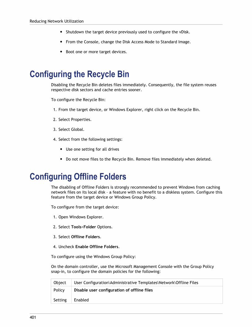
● Shutdown the target device previously used to configure the vDisk.
● From the Console, change the Disk Access Mode to Standard Image.
● Boot one or more target devices.
Configuring the Recycle BinDisabling the Recycle Bin deletes files immediately. Consequently, the file system reusesrespective disk sectors and cache entries sooner.
To configure the Recycle Bin:
1. From the target device, or Windows Explorer, right click on the Recycle Bin.
2. Select Properties.
3. Select Global.
4. Select from the following settings:
● Use one setting for all drives
● Do not move files to the Recycle Bin. Remove files immediately when deleted.
Configuring Offline FoldersThe disabling of Offline Folders is strongly recommended to prevent Windows from cachingnetwork files on its local disk – a feature with no benefit to a diskless system. Configure thisfeature from the target device or Windows Group Policy.
To configure from the target device:
1. Open Windows Explorer.
2. Select Tools>Folder Options.
3. Select Offline Folders.
4. Uncheck Enable Offline Folders.
To configure using the Windows Group Policy:
On the domain controller, use the Microsoft Management Console with the Group Policysnap-in, to configure the domain policies for the following:
Object User Configuration\Administrative Templates\Network\Offline Files
Policy
Setting
Disable user configuration of offline files
Enabled
Reducing Network Utilization
401
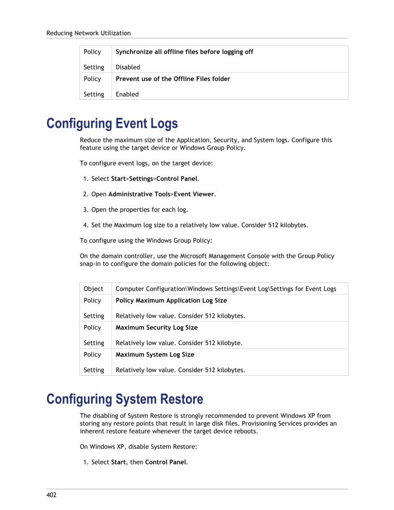
Policy
Setting
Synchronize all offline files before logging off
Disabled
Policy
Setting
Prevent use of the Offline Files folder
Enabled
Configuring Event LogsReduce the maximum size of the Application, Security, and System logs. Configure thisfeature using the target device or Windows Group Policy.
To configure event logs, on the target device:
1. Select Start>Settings>Control Panel.
2. Open Administrative Tools>Event Viewer.
3. Open the properties for each log.
4. Set the Maximum log size to a relatively low value. Consider 512 kilobytes.
To configure using the Windows Group Policy:
On the domain controller, use the Microsoft Management Console with the Group Policysnap-in to configure the domain policies for the following object:
Object Computer Configuration\Windows Settings\Event Log\Settings for Event Logs
Policy
Setting
Policy Maximum Application Log Size
Relatively low value. Consider 512 kilobytes.
Policy
Setting
Maximum Security Log Size
Relatively low value. Consider 512 kilobyte.
Policy
Setting
Maximum System Log Size
Relatively low value. Consider 512 kilobytes.
Configuring System RestoreThe disabling of System Restore is strongly recommended to prevent Windows XP fromstoring any restore points that result in large disk files. Provisioning Services provides aninherent restore feature whenever the target device reboots.
On Windows XP, disable System Restore:
1. Select Start, then Control Panel.
Reducing Network Utilization
402
2. Open System.
3. Select System Restore.
4. Check Turn off System Restore.
Configuring Logical PrefetchDisabling Logical Prefetcher prevents Windows XP from caching additional files.
To disable logical prefetcher, set the following registry value to 0 (zero):
HKLM\SYSTEM\CurrentControlSet\Control\Session Manager\MemoryManagement\PrefetchParameters\EnablePrefetcher
Configuring Automatic Disk DefragmentationDisabling Automatic Disk Defragmentation prevents Windows XP from filling the vDisk writecache by automatically de-fragmenting the vDisk during boot time.
To disable automatic disk defragmentation, set the following registry key value data:
Key HKEY_LOCAL_MACHINE\Microsoft\Dfrg\BootOptimizeFunction
Value Name Enable
Value Type REG_SZ
Value Data N
Disabling Windows Automatic UpdatesIf you have the Windows Automatic Updates service running on your target device, Windowsperiodically checks a Microsoft Web site and looks for security patches and system updates.If it finds updates that have not been installed, it attempts to download them and installthem automatically. Normally, this is a useful feature for keeping your system up-to-date.However, in a Provisioning Services implementation using Standard Image mode, thisfeature can decrease performance, or even cause more severe problems. This is becausethe Windows Automatic Updates service downloads programs that fill the write cache.When using the target device’s RAM cache, filling the write cache can cause your targetdevices to stop responding.
Re-booting the target device clears both the target device and Provisioning Services writecache. Doing this after an auto-update means that the Automatic Updates changes are lost,which defeats the purpose of running Automatic Updates. (To make Windows updatespermanent, you must apply them to a vDisk while it is in Private Image mode).
To prevent filling your write cache, make sure to disable the Windows Automatic Updatesservice for the target device used to build the vDisk.
Reducing Network Utilization
403
To disable the Windows Automatic Updates feature:
1. Select Start>Settings>Control Panel>Administrative Tools.
2. Select System.
3. Click the Automatic Updates tab.
4. Select the Turn Off Automatic Updates radio button.
5. Click Apply.
6. Click OK.
7. Select Services.
8. Double-click the Automatic Updates service.
9. Change the Startup Type by selecting Disabled from the drop-down list.
10. If the Automatic Updates service is running, click the Stop button to stop the service.
11. Click OK to save your changes.
To make Windows updates permanent:
1. Shutdown all target devices that share the vDisk.
2. Change the vDisk mode to Private image.
3. Boot one target device from that vDisk.
4. Apply Windows updates.
5. Shutdown the target device.
6. Change vDisk mode to Standard image.
7. Boot all target devices that share this vDisk.
Reducing Network Utilization
404
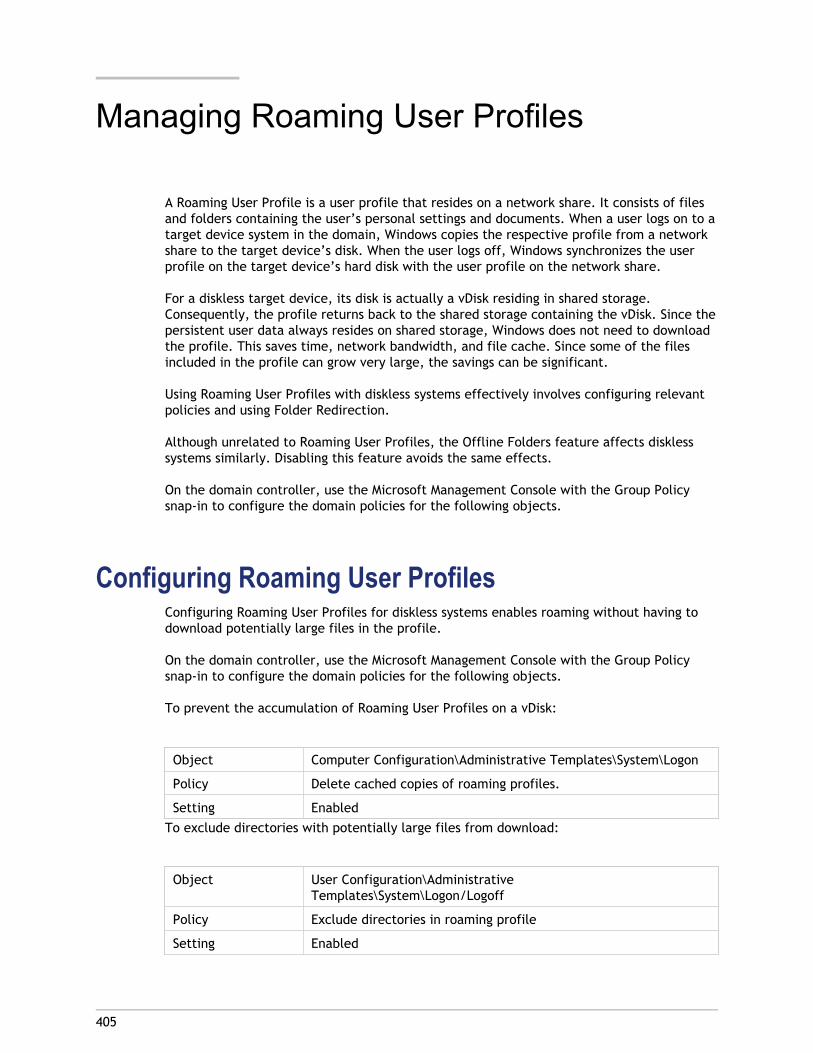
405
Managing Roaming User Profiles
A Roaming User Profile is a user profile that resides on a network share. It consists of filesand folders containing the user’s personal settings and documents. When a user logs on to atarget device system in the domain, Windows copies the respective profile from a networkshare to the target device’s disk. When the user logs off, Windows synchronizes the userprofile on the target device’s hard disk with the user profile on the network share.
For a diskless target device, its disk is actually a vDisk residing in shared storage.Consequently, the profile returns back to the shared storage containing the vDisk. Since thepersistent user data always resides on shared storage, Windows does not need to downloadthe profile. This saves time, network bandwidth, and file cache. Since some of the filesincluded in the profile can grow very large, the savings can be significant.
Using Roaming User Profiles with diskless systems effectively involves configuring relevantpolicies and using Folder Redirection.
Although unrelated to Roaming User Profiles, the Offline Folders feature affects disklesssystems similarly. Disabling this feature avoids the same effects.
On the domain controller, use the Microsoft Management Console with the Group Policysnap-in to configure the domain policies for the following objects.
Configuring Roaming User ProfilesConfiguring Roaming User Profiles for diskless systems enables roaming without having todownload potentially large files in the profile.
On the domain controller, use the Microsoft Management Console with the Group Policysnap-in to configure the domain policies for the following objects.
To prevent the accumulation of Roaming User Profiles on a vDisk:
Object Computer Configuration\Administrative Templates\System\Logon
Policy Delete cached copies of roaming profiles.
Setting EnabledTo exclude directories with potentially large files from download:
Object User Configuration\AdministrativeTemplates\System\Logon/Logoff
Policy Exclude directories in roaming profile
Setting Enabled
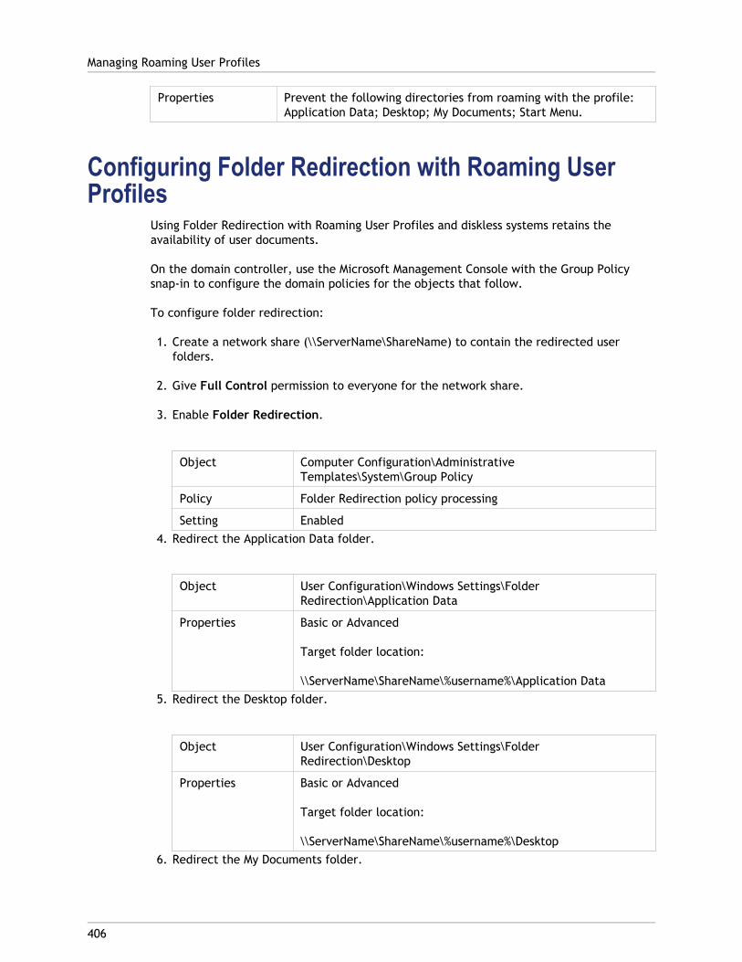
Properties Prevent the following directories from roaming with the profile:Application Data; Desktop; My Documents; Start Menu.
Configuring Folder Redirection with Roaming UserProfiles
Using Folder Redirection with Roaming User Profiles and diskless systems retains theavailability of user documents.
On the domain controller, use the Microsoft Management Console with the Group Policysnap-in to configure the domain policies for the objects that follow.
To configure folder redirection:
1. Create a network share (\\ServerName\ShareName) to contain the redirected userfolders.
2. Give Full Control permission to everyone for the network share.
3. Enable Folder Redirection.
Object Computer Configuration\AdministrativeTemplates\System\Group Policy
Policy Folder Redirection policy processing
Setting Enabled4. Redirect the Application Data folder.
Object User Configuration\Windows Settings\FolderRedirection\Application Data
Properties Basic or Advanced
Target folder location:
\\ServerName\ShareName\%username%\Application Data5. Redirect the Desktop folder.
Object User Configuration\Windows Settings\FolderRedirection\Desktop
Properties Basic or Advanced
Target folder location:
\\ServerName\ShareName\%username%\Desktop6. Redirect the My Documents folder.
Managing Roaming User Profiles
406
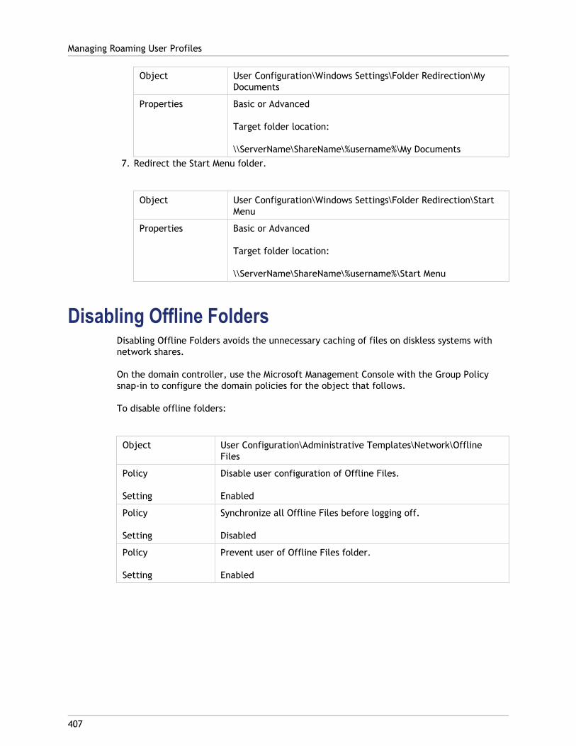
Object User Configuration\Windows Settings\Folder Redirection\MyDocuments
Properties Basic or Advanced
Target folder location:
\\ServerName\ShareName\%username%\My Documents7. Redirect the Start Menu folder.
Object User Configuration\Windows Settings\Folder Redirection\StartMenu
Properties Basic or Advanced
Target folder location:
\\ServerName\ShareName\%username%\Start Menu
Disabling Offline FoldersDisabling Offline Folders avoids the unnecessary caching of files on diskless systems withnetwork shares.
On the domain controller, use the Microsoft Management Console with the Group Policysnap-in to configure the domain policies for the object that follows.
To disable offline folders:
Object User Configuration\Administrative Templates\Network\OfflineFiles
Policy
Setting
Disable user configuration of Offline Files.
Enabled
Policy
Setting
Synchronize all Offline Files before logging off.
Disabled
Policy
Setting
Prevent user of Offline Files folder.
Enabled
Managing Roaming User Profiles
407
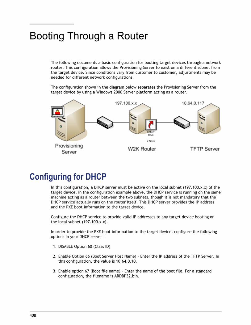
408
Booting Through a Router
The following documents a basic configuration for booting target devices through a networkrouter. This configuration allows the Provisioning Server to exist on a different subnet fromthe target device. Since conditions vary from customer to customer, adjustments may beneeded for different network configurations.
The configuration shown in the diagram below separates the Provisioning Server from thetarget device by using a Windows 2000 Server platform acting as a router.
Configuring for DHCPIn this configuration, a DHCP server must be active on the local subnet (197.100.x.x) of thetarget device. In the configuration example above, the DHCP service is running on the samemachine acting as a router between the two subnets, though it is not mandatory that theDHCP service actually runs on the router itself. This DHCP server provides the IP addressand the PXE boot information to the target device.
Configure the DHCP service to provide valid IP addresses to any target device booting onthe local subnet (197.100.x.x).
In order to provide the PXE boot information to the target device, configure the followingoptions in your DHCP server :
1. DISABLE Option 60 (Class ID)
2. Enable Option 66 (Boot Server Host Name) – Enter the IP address of the TFTP Server. Inthis configuration, the value is 10.64.0.10.
3. Enable option 67 (Boot file name) – Enter the name of the boot file. For a standardconfiguration, the filename is ARDBP32.bin.
Configuring the Provisioning Services for PXEUsing the Console, configure the bootstrap settings to use the Gateway and Subnet maskfields. These fields should reflect the gateway and subnet to be used by the target device.In this case, they are 197.100.x.x for the gateway, and 255.255.255.0 for the netmask.
Verify the TFTP service is running on the Provisioning Server.
The PXE Service on the Provisioning Server in the above configuration is not necessary sinceoptions 66 & 67 in the router’s DHCP service provide the same information to the targetdevice. You can stop the PXE Service on the Provisioning Server if you have no targetdevices on the Provisioning Server subnet needing its functionality. The same is true for anyDHCP service running on the Provisioning Server itself.
Running PXE and DHCP on the Same ComputerIf PXE and DHCP are running on the same Provisioning Server, an option tag must be addedto the DHCP configuration. This tag indicates to the target devices (using PXE) that theDHCP server is also the PXE boot server. Verify that option tag 60 is added to your DHCPscope. Provisioning Services setup automatically adds this tag to your scope provided thatthe Microsoft DHCP server is installed and configured before installing Provisioning Services.The Configuration Wizard sets-up the Tellurian DHCP Server configuration file if you use thewizard to configure Provisioning Services.
The following is an example Tellurian DHCP Server configuration file which contains theoption 60 tag.
max-lease-time 120;default-lease-time 120;option dhcp-class-identifier "PXEClient";subnet 192.168.4.0 netmask 255.255.255.0 {option routers 192.168.123.1;range 192.168.4.100 192.168.4.120;}.
Booting Through a Router
409
410
Updating NIC Drivers
From time to time, you may need to upgrade the drivers for your network interface cards(NICs). Follow the guidelines below for upgrading NIC drivers.
Upgrading NIC Drivers on Target DevicesNote: Do not attempt to upgrade a NIC driver on a vDisk. Do not attempt to upgrade aNIC driver on a hard disk on which the Provisioning Server is currently installed.Improperly upgrading a NIC may make the hard drive unable to boot.
To upgrade NIC drivers for target devices:
1. Go to the target device with the original hard drive from which you made the vDiskimage.
2. Set the system BIOS to boot from the hard drive.
3. Re-boot the target device directly from the hard drive.
4. Un-install the target device software from this hard drive.
5. Upgrade NIC driver as directed by the manufacturer's instructions.
6. Re-install the target device software on the hard drive.
7. Re-image the hard drive to make a new vDisk image.
Upgrading NIC Drivers on a Provisioning ServerTo upgrade NIC drivers on any Provisioning Server, simply follow the manufacturerinstructions for upgrading NIC drivers.
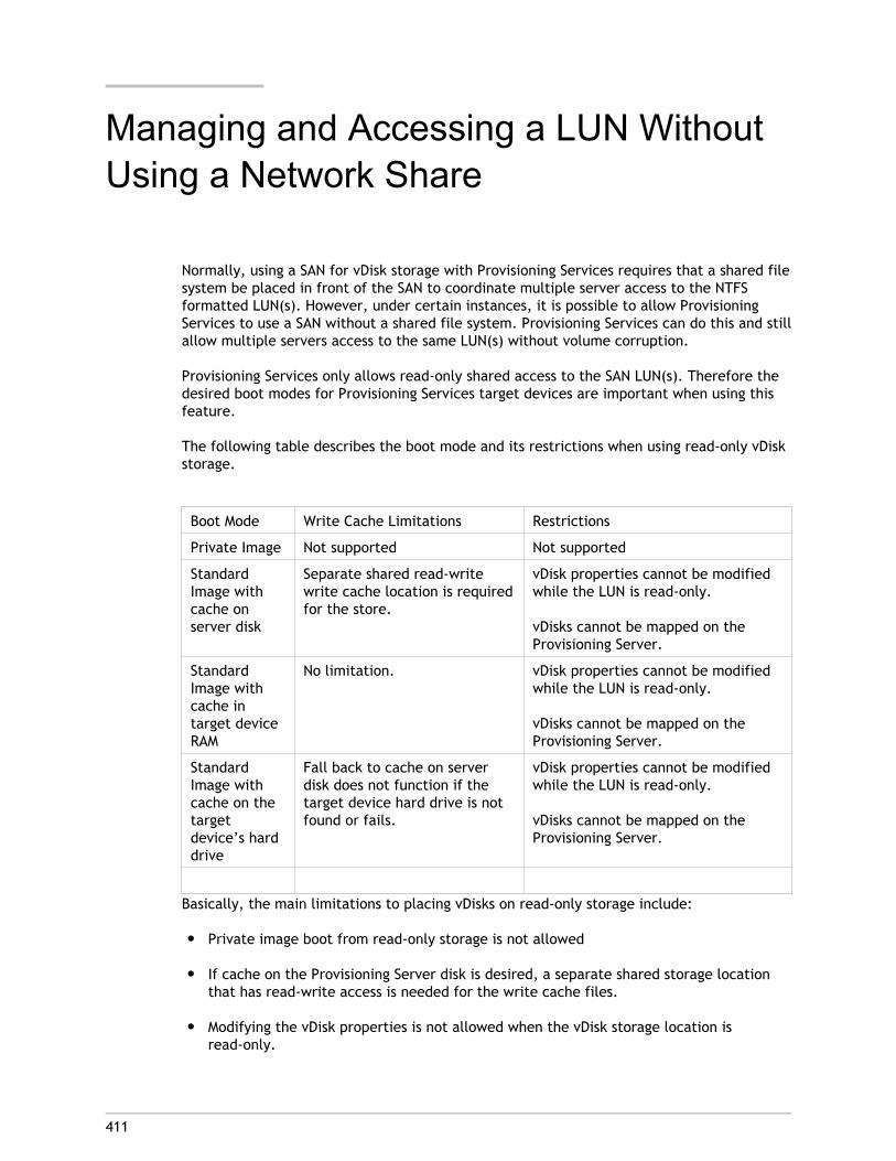
411
Managing and Accessing a LUN WithoutUsing a Network Share
Normally, using a SAN for vDisk storage with Provisioning Services requires that a shared filesystem be placed in front of the SAN to coordinate multiple server access to the NTFSformatted LUN(s). However, under certain instances, it is possible to allow ProvisioningServices to use a SAN without a shared file system. Provisioning Services can do this and stillallow multiple servers access to the same LUN(s) without volume corruption.
Provisioning Services only allows read-only shared access to the SAN LUN(s). Therefore thedesired boot modes for Provisioning Services target devices are important when using thisfeature.
The following table describes the boot mode and its restrictions when using read-only vDiskstorage.
Boot Mode Write Cache Limitations Restrictions
Private Image Not supported Not supported
StandardImage withcache onserver disk
Separate shared read-writewrite cache location is requiredfor the store.
vDisk properties cannot be modifiedwhile the LUN is read-only.
vDisks cannot be mapped on theProvisioning Server.
StandardImage withcache intarget deviceRAM
No limitation. vDisk properties cannot be modifiedwhile the LUN is read-only.
vDisks cannot be mapped on theProvisioning Server.
StandardImage withcache on thetargetdevice’s harddrive
Fall back to cache on serverdisk does not function if thetarget device hard drive is notfound or fails.
vDisk properties cannot be modifiedwhile the LUN is read-only.
vDisks cannot be mapped on theProvisioning Server.
Basically, the main limitations to placing vDisks on read-only storage include:
● Private image boot from read-only storage is not allowed
● If cache on the Provisioning Server disk is desired, a separate shared storage locationthat has read-write access is needed for the write cache files.
● Modifying the vDisk properties is not allowed when the vDisk storage location isread-only.
● Mounting the vDisk on the server is not allowed when the vDisk storage location isread-only.
PrerequisitesThe following are prerequisites to using this new feature:
● Provisioning Servers that will have access to the read-only shared LUN(s) are serverclass machines (Windows 2003 Server or 2008 Server).
● The Microsoft iSCSI initiator software is installed on all Provisioning Servers that willhave access to the SAN.
● The vDisk files that will be placed on the read-only shared LUN(s) have already beencreated and reside on a normal read-write storage location. Creating vDisk files in placeon the LUN is more difficult than pre-making the VHD files in a normal read-write storeand subsequently copying them to the shared LUN. Therefore, this document willdescribe the procedure assuming the vDisk files have been pre-made and reside in anormal read-write storage location.
● The SAN being used has the ability to set a LUN up for shared read-write access orshared read-only access without requiring a shared file system front end. Normally,using a LUN in shared read-write access mode without a shared file system front endwill result in a corrupt NTFS volume. Limiting the LUN access to read-only circumventsthis problem.
ImplementationOn the SAN
1. Create a volume on the EquaLogic SAN using the EqualLogic Group Manager (or otherrelevant SAN interface front end). Make the volume large enough to hold all VHD andVHD associated PVP files that will be shared between the Provisioning Servers.
2. Set the access type for the volume to read/write - shared. Note that the volume will bemade read-only through the NTFS attributes not through the SAN access rights. Whileusing the volume in read-only shared mode is possible, it requires extra steps toimplement the solution. Therefore this procedure describes the process when thevolume is set for read-write – shared access.
On Provisioning Servers
1. Use the iSCSI Initiator to login to the SAN volume on only one of the ProvisioningServers.
Note: Do NOT login to the SAN Volume from more than one server simultaneouslyuntil the volume has been marked read-only. If you allow more than one server tosimultaneously login to the volume through the iSCSI interface while the volume isread-write, you will corrupt the volume and will need to re-format it. All data onthe volume will be lost.
Managing and Accessing a LUN Without Using a Network Share
412
2. Format the volume through the Windows Disk Manager with an NTFS file system andassign a drive letter or mount point path. A mount point path is desirable if you willhave many LUN/Volumes exposed on a server as there will be no drive letterlimitations. Make sure you use a drive letter/Mount point that will be identical on allservers using the volume. If you cannot make them identical, you will need to use theProvisioning Services/store override paths to point a specific server to a different driveletter/mount point for the volume.
3. After the volume is formatted and assigned a drive letter/Mount point, the volumeshould be accessible on this single Provisioning Server as a read/write volume. Makesure all properties for the VHD and PVP files that will reside on the volume are setcorrectly (including enabling HA) and then copy all VHD files and their associated PVPfiles to the volume. Lock files do not need to be copied. The PVP file MUST be copiedalong with the VHD file. The system will not be able to create a PVP file ‘on the fly’once the volume is read-only.
4. After all files are copied to the volume, you must make the volume read-only. Close allExplorer windows that have access to the volume, then open a command prompt on theserver that has access to the volume.
5. Run diskpart.exe. This will start an interactive session with diskpart.exe.
6. Find the volume number by typing the following command: list volume.
7. Note the volume number of your volume and select it by typing the following command:select volume volumeNumber where volumeNumber is the number of the volumeidentified with the list volume command.
8. After the volume is selected, set the read-only attribute of the volume by typing thefollowing command: attributes volume set readonly.
9. Check that the readonly attribute was set correctly by typing the following command:detail volume.
10. Exit diskpart.exe by typing the command: exit.
11. Using the iSCSI initiator interface, logoff the volume on this server and then re-login tothe volume again. Make sure to make the volume a persistent target. You must logoffand then login to the volume to get NTFS on the server to re-read the volume attributesso that it will recognize the volume as read-only. Making the volume a persistent targetwill ensure the volume is accessible when the server reboots.
12. It is now safe to mount the iSCSI volume on all Provisioning Servers. Using the iSCSIInitiator applet and Microsoft Disk Manager, mount the volume on all ProvisioningServers that need access to the volume. Make the target persistent in the iSCSIinterface and try to make all servers mount using the same drive letter or mount point,which makes setting up the Provisioning Services Store easier.
Note: It may be necessary to make the Provisioning Services’ Stream Service on allservers dependent on the iSCSI Service. This ensures that the volumes are available atthe proper time should the server reboot and target devices are booted during theserver reboot. To do this, edit the registry for the Stream Service, then add theDependsOnService value pointing to the iscsiexe.exe service (MSiSCSI).
13. Run the Console on one of the Provisioning Servers to create a store that points to thedrive letter/mount point for the volume.
Managing and Accessing a LUN Without Using a Network Share
413
14. Select which Provisioning Servers have access to the volume for this store.
Note: If you are using Cache on server or Difference disk mode for any VHDs on thevolume, you MUST enter a Default write cache path for the store that does NOT pointto the SAN read-only volume. This path must be in a shared location for allProvisioning Servers. You can use a Windows Network Share or any other read-writeshared storage device, but the write cache path cannot point to the read-onlyvolume. The read-only volume can only contain the VHD and PVP files. If you areusing one of the target device cache modes (local HD or RAM) then you do not needto set up a shared read-write write cache location for the store.
15. On the Console, right-click on the store then select the Add Existing Disk… menuoption, which scans the store and adds the VHD files to the database.
16. Assign the VHD files that are on this store to target devices, then boot those targetdevices normally. The VHD files on the read-only volume will always display in theConsole as locked with the lock type: Read only media: Shared. You cannot removethis lock type. You cannot create a new vDisk on a store once it has been marked asread-only with diskPart.exe. You cannot edit the properties of the VHD once the storehas been marked read-only.
Modifying vDisk PropertiesvDisk properties cannot be modified while the SAN LUN location is marked read-only. Toedit the vDisk properties or modify the vDisk files on the LUN, complete the followingprocedure:
1. Shutdown all target devices that use the VHDs that are on the store.
2. Use the iSCSI initiator on all Provisioning Servers (except one) to logoff the volume.Alternately, use the diskpart.exe utility on some server OS types and mark the volumeas offline on all Provisioning Servers (this feature is not available on all OS types. Ifnecessary, use the iSCSI initiator to logoff the volumes).
3. In order to use the diskpart.exe utility to mark the volume as read/write, Open acommand prompt on the server that has access to the volume, then rundiskpart.exe. This starts an interactive session with diskpart.exe.
4. Find the volume number by typing the following command: list volume.
5. Note the volume number of your volume and select it by typing the following command:select volume volumeNumber where volumeNumber is the number of the volumeidentified with the list volume command.
6. After the volume is selected, to clear the readonly attribute, type the followingcommand: attributes volume clear readonly.
7. Check that the readonly attribute was set correctly by typing the following command:detail volume.
8. Exit diskpart.exe by typing the command: exit.
Managing and Accessing a LUN Without Using a Network Share
414
9. Logoff/login the volume (or mark it offline/online in diskpart) on the single server thatstill has access to the volume.
10. Edit the VHD file attributes through the Console, then copy the new files to the volume.
11. After all edits are complete, use the diskpart.exe utility to mark the volume read-onlyby selecting the volume, then setting the read-only attribute: attributes volume setreadonly.
12. Check that the readonly attribute was set correctly by typing the following command:detail volume
13. Exit diskpart.exe by typing the command: exit.
14. Use the iSCSI Initiator to logoff, then relogin to the volume to re-read the read-onlyattributes.
15. Use the iSCSI Initiator on all Provisiong Servers to re-login to the volume.
Note: IMPORTANT! Do NOT login to the SAN Volume from more than one serversimultaneously until the volume has been marked read-only. If you allow more thanone server to simultaneously login to the volume through the iSCSI interface while thevolume is read-write, you will corrupt the volume and will need to re-format it. Alldata on the volume will be lost.
Managing and Accessing a LUN Without Using a Network Share
415

416
Managing Printers
Provisioning Server provides a Printer Management feature that allows you to manage whichprinters target devices have access to on a vDisk. Printers are managed from the TargetDevice Properties dialog.
This feature should not be enabled if you use Active Directory to manage printers. If youuse an existing printer management tool, this feature should be disabled to avoid printersetting conflicts.
Printers can only be added to the top-level differencing disk version while it is underMaintenance or if it is a Private Image. If a device boots from a previous version, the printerconfiguration may not match.
There are two types of printers that can appear in the Console window:
● Network Printers
● Local Printers
Before a target device can access a printer, the following tasks must be completed in theorder that follows:
● Installing Printers on the vDisk
● Enabling Printers on the vDisk
● Enabling the Printer Management Feature

417
Installing Printers on a vDisk
Printers must be installed on the vDisk image before the printers are available to targetdevices booting from that disk. Printers can only be added to the top-level differencing diskversion while it is under Maintenance or if it is a Private Image. If a device boots from aprevious version, the printer configuration may not match.
To install printers on the vDisk:
1. Change the vDisk image mode to Private Image mode.
2. Install the required printers on the target device that is using the vDisk.
3. Perform a clean shut-down of the target device that is using the vDisk.
4. If this vDisk is shared by users, change the vDisk image mode back to Shared Imagemode.
5. Verify that the printers display in the Console:
a. Right-click on the target device, select the Properties menu option.
b. Select the vDisks tab, then click on the Printers button. Printers associated withthat vDisk should appear in the list of available printers.
After successfully installing printers, the next step is to enable printers for target devicesthat access this vDisk (for details, refer to enable printers for target devices).

418
Enabling or Disabling Printers on a vDisk
Note: The Printer Management feature is only recommended if you are not using ActiveDirectory to manage printer groups.
By default, printers are not enabled on the vDisk. Enable or disable printers from theTarget Device Properties vDisk tab. On the Printers dialog, enable the checkbox next toeach printer to enable or disable it. After enabling (assigning) printers to target devices,the Printer Management feature must then be enabled on the vDisk.
Until Printer Management is enabled, all printers that are installed on the target device areavailable to that target device. By enabling Printer Management, you can select printers orremove printers from individual target devices.
After a target device boots, printer information, which is included in a vDisk image,becomes available to target devices. Printer Management is initially disabled until allprinter-to-target device assignments are completed for the vDisk. Disabling individualprinters prohibits target devices from accessing those printers.
Note: Disabling printers does not remove the printer information from the vDisk. Changesto the target devices printer assignments do not occur until the target device reboots.
Examples of reasons you may want to disable Printer Management include:
● You may be using a different printer system that installs the valid printers on eachtarget device and software may delete them or cause conflicting settings.
● Printers that are included on the vDisk should be accessible to all users.
● The system needs to be configured before being deployed. Until the PrinterManagement feature is enabled, changes can be made for different target devices asneeded.
All printers installed on a vDisk appear in the Details panel when the Printers group folder isexpanded for that vDisk.
If a disk is a HA vDisk (has a duplicate with same vDisk name), changes to that printer (if itis enabled or disabled for a target device) are automatically made to the duplicate vDisk.
Enablement Methods
Using the Console, you can manage which target devices use which printers. There areseveral methods for managing target device printer assignments. Choose from the followingmethods:
● Enabling printers for target devices using the Printer settings option. Use this method toenable or disable a single printer to multiple target devices accessing a vDisk.
● Enabling printers for target devices using the Printers group folder. Use this method toselect printer settings (enable/disable; default) for a single target device.

● Enabling printers using Copy and Paste. Use this method to copy printer settings of onetarget device (enabled/disabled; default printer), to one or more target devicesselected in the Details panel.
● Enabling printers using an existing target device as a template. Use this method toautomatically set printer settings when a target device is added to the network.
Note: The Administrator may choose to limit the number of printers for particular targetdevices or select different default printers for particular target devices. The settings thatare selected are saved to the target device’s personality information (if the limit for thisfield, 65K, is reached, a message appears indicating that some of the settings will not besaved and offers suggestions for decreasing the size).
Enabling or Disabling Printers on a vDisk
419

420
Methods for Enabling Printers on a vDisk
Choose from the following methods to enable printers on a vDisk:
● Enabling printers for target devices using the Printer Settings option
● Enabling printers for target devices using the Printers group folder
● Enabling printers using Copy and Paste
● Enabling printers using an existing target device as a template
Enabling printers for target devices using the PrinterSettings option
Use this method to assign a single printer to multiple target devices. This method is veryuseful when managing the printer-to-all target devices relationship.
1. In the Console tree, under Provisioning Servers, click the Printers group folder. Allprinters associated with that group appear in the Details panel.
2. Right-click on a printer in the Details panel, then select the Client Printer Settings...menu option. The printer settings dialog for that printer appears.
3. Enable or disable this printer for one or more target devices using any of the followingoptions:
● In the Enable column, select the checkbox next to each target device to enable ordisable use of this printer.
● Select the checkbox under the dialogs Enable heading to enable or disable thisprinter for all target devices assigned to the vDisk.
4. To select this printer as the default printer for target devices accessing this vDisk,select from the following methods:
● Select the Default checkbox in the dialogs Default heading to set this printer as thedefault for all target devices assigned to this vDisk.
● Highlight one or more target devices, then right-click to open the context menu.Select from the following menu options; Default, NotDefault All Default All NotDefault
● In the Default column, select the checkbox next to each target device that shoulduse this printer as the default printer. If there is only one printer, that printer isautomatically set as the default printer.
5. Click OK to save settings for this printer and exit the dialog.

Enabling printers for target devices using the Printersgroup folder
Use this method to select printer settings (enable/disable; default) for a single targetdevice.
Note: After selecting printer settings for a single target device, you may choose toduplicate this target devices printer settings using the Copy and Paste features.
1. Under the target device’s vDisk, click the Printers group folder in the tree. Printers thatare associated with that group appear in the Details panel. By default, printers are notenabled for a target device and the first printer listed is set as the default printer.
2. Select or deselect the Enable checkbox next to each printer to enable or disable theprinter for this target device. You can also choose from one of the additional selectionmethods that follow.
In the Details panel:
● Select or unselect the Enable checkbox within the table heading to enable ordisable all printers.
● Highlight a printer, then use the space bar to enable or disable printers.
Enabling printers using Copy and PasteUse this method to set the same printer settings (enabled/disabled; default printer) thatexist for one target device, to one or more target devices that use the same vDisks. Thismethod is particularly useful when adding new target devices and those target devices usethe same vDisks, and therefore the same printers, as an existing target device.
1. In the Console, right-click on the target device that you want to copy printer settingsfrom.
2. Select the Copy menu option. The Copy target device properties dialog appears.
3. Under Options, select Printers, then click OK to exit the dialog.
4. In the Tree, highlight the Target Devices directory so that all target devices appear inthe Details panel.
5. Highlight one or more target devices that you want to paste the printer settings to(enable/disable; default).
6. Right-click on the highlighted target devices, then select the Paste menu option.
Methods for Enabling Printers on a vDisk
421

Enabling printers using an existing target device as atemplate
Use this method if you want all new target devices, that are being added to your network,to automatically share printer settings (enable/disable; default).
1. In the Console, double-click the target device that you want to select as the template.The Target Device Properties dialog appears.
2. On the General tab, select the Set as default target device option.
3. Click OK to exit the dialog.
Methods for Enabling Printers on a vDisk
422
423
Enabling the Printer Management Feature
Note: The Printer Management feature is only recommended if you are not using ActiveDirectory.
After assigning printers to target devices, the Printer Management feature must be enabledbefore any printers on the target device can be removed. Until Printer Management isenabled, all printers installed on the target device are available to the target device. Oncethe feature is enabled, any changes to target devices printer settings (enable/disable;default) become available the next time the target device boots from the vDisk.
If the Printer Management feature is disabled and a target device boots from a vDisk thathas printers installed on it, that target device has access to all printers on that vDisk. If thePrinter Management feature is enabled and the target device boots from that same vDisk,that target device can only access those printers that are enabled for that target device.
To enable or disable printers on a selected vDisk:
1. In the Console, expand the Provisioning Server node in the tree panel, then select thevDisk that you want printers enabled or disabled on.
2. Select File Properties from the right-click menu, then select the Options tab.
3. Under Printer Settings, select the Enable the Printer Settings checkbox option toenable settings, or leave the checkbox blank to disable printer settings.
4. If the Enable the Printer Management checkbox is selected, the Enable PrinterManagement menu options appear checked when the Printers group is highlighted.
5. If the Enable the Printer Management checkbox appears disabled, all printers exist onthe selected vDisk.
You can also choose from the following methods to enable or disable the PrinterManagement feature using right-click menus:
Printers Group
In the Tree, under Provisioning Servers, expand a Provisioning Server, then expand the vDiskfor which you want to disable Printer Management. Right-click on the Printers folder forthat vDisk, then select the Disable Printer Management option.
Virtual Disk
In the Tree, under Provisioning Servers, right click on the vDisk for which you want todisable Printer Management, then select the Disable Printer Management option.
424
Updating vDisks on Physical Devices
Note: This vDisk update method can only be used on a base disk that has no VHD versionsassociated with it.
This vDisk update method provides a way to update a vDisk on a physical machine withouthaving to re-install a hard drive in a diskless target device, or reconfigure all your targetdevice database records. Use this method when adding or removing third-party softwareapplications or files to your vDisk. (This method is not intended for updating thetarget-device software).
Setting vDisk Class and Type Properties
The automatic update process takes advantage of the target device and disk properties ofClass and Type. A Class can be assigned to target devices and vDisks. Additionally, thevDisk has the additional property, Type. In order for an automatic update to take place, theClass of the target device and vDisk must match. For a newer vDisk to replace an oldervDisk within a target device, the vDisk Type of both vDisks must match.
Since multiple, duplicate vDisk instances can exist within your implementation, and thosevDisks can be assigned to one or more target devices (in the case of Provisioning ServerLeast Busy and First Available boot behaviors), it is necessary to further qualify the oldvDisk that will be replaced by the new vDisk. This is the reason for the Type property of thevDisk. If you want to use the Automatic Disk Image Update feature, you should never assignmore than one vDisk from the same Provisioning Server with the same Type, to the sametarget device.
Automatic Update Procedures
Automatically Updating a vDisk consists of the following procedures:
1. Enable automatic updates on the original vDisk image file
2. Make a copy of the original vDisk to use to update another vDisk
3. Add the new vDisk file to the database
4. Change the disk access mode
5. Assign the new vDisk
6. Boot the target device from the new vDisk
7. Add software or data files to the vDisk
8. Change the vDisk access mode of the new vDisk
9. Increment the version number
Note: During the update process, if several vDisks exist with the same version number because the version number was not incremented, Provisioning Services uses the first
updated vDisk presented in the list.
10. Update the vDisk
These procedures are described in detail below.
Enable automatic updates on the original vDisk imagefile
1. In the Console, right-click on the original vDisk (ORIGINAL), then select Properties.
2. Select the Auto Update tab.
3. Select the Enable automatic updates for this vDisk option, then click OK.
Make a copy of the original vDisk to use to updateanother vDisk
1. On the Provisioning Server, open Windows Explorer.
2. Navigate to the directory where you store your vDisk image files.
3. Right-click on the vDisk image file (.vhd) and its properties file (.pvp) that you want toupdate, then select Copy from the shortcut menu.
4. Right-click again anywhere in the vDisk directory, then select Paste from the shortcutmenu.
5. For each file, right-click on the file, then select Rename from the shortcut menu. Entera new name for the files. (For the documentation purposes, the new vDisk file will bereferred to as the NEW.vhd file).
Select the Enable automatic updates for this vDisk option, then click OK.
You should now have both the original vDisk image file (ORIGINAL.vhd; ORIGINAL.pvp)and a new copy of the vDisk image file (NEW.vhd; NEW.pvp) in your vDisk directory.
Add the new vDisk file to the databaseUse the Console to create the vDisk file in the Provisioning Services database.
Changing the disk access mode1. In the Console, right-click on the new vDisk file (NEW.vhd).
2. Select the File Properties menu option.
3. On the Mode tab, select Private Image, then click OK.
Updating vDisks on Physical Devices
425
Assigning the new vDisk1. In the Console, right-click on a target device, then select Properties.
2. On the vDisks tab, select the original vDisk (ORIGINAL) from the vDisks list, then clickthe Remove button.
3. From the vDisks list, select the new vDisk (NEW), then click the Add button
4. Click OK to save the change
Booting the target device from the new vDiskAfter assigning the new vDisk to the target device, boot the target device from the newvDisk (NEW) to confirm that the new vDisk was updated correctly.
Adding software or data files to the vDisk1. On the master target device, install or remove the desired software or files. (For
example, install a new software application or perform a live update of your anti-virusdefinition files.)
2. When you have finished updating your new vDisk (NEW) with the desired software or filechanges, shut down the target device.
Changing the vDisk access mode of the new vDisk1. In the Console, right-click on the new vDisk (NEW), then select File Properties.
2. On the Mode tab, select the access mode to be exactly the same as that of your originalvDisk (ORIGINAL).
3. From the cache drop-down menu, select the same cache type that was selected foryour original vDisk (ORIGINAL), then click OK. The Disk Access Mode and Cache Typemust be exactly the same for both the original vDisk image (ORIGINAL), and the newcopy of the vDisk (NEW).
Incrementing the version number1. In the Console, right-click on the new vDisk (NEW), then click the File Properties
button.
2. Select the Identification tab.
3. Increment the Build number by one, then click OK.
Updating vDisks on Physical Devices
426

Update vDisks1. Right-click on the vDisk Pool, then select the Check for Updates menu option.
2. Select the Check for Automatic Updates menu option, then click the OK button on theconfirmation dialog.
3. Boot target devices from the newly updated vDisk.
Updating vDisks on Physical Devices
427
428
Using the Streamed VM Setup Wizard
Using the WizardThe Provisioning Services Streamed VM Setup Wizard assists in deploying a ProvisioningServices streamed vDisk to a number of cloned virtual machines (VMs).
Use the wizard to:
● Create VMs on a supported hosted hypervisor from an existing template:
● XenServer
● Hyper-V via SCVMM
● ESX via V-Center● Create Provisioning Services target devices within a Collection
● Assign a vDisk image that is in Standard Image mode to the VMs
Before running the wizard, be sure that the following prerequisites are met:
● One or more hypervisor hosts exist with a configured template.
● A Device Collection exists in the Provisioning Services Site .
● A vDisk in Standard Image mode exists, to be associated with selected VM template.
● Template VM Requirements:
● Boot order: Network/PXE first in list (as with physical machines).
● Hard disks: If using local write cache, an NTFS formatted disk large enough for thecache must exist. Otherwise, no hard disks are required.
● Network: Static MAC addresses. If using XenServer, address cannot be00-00-00-00-00-00
● The Provisioning Services Console user account was added to a PVS SiteAdmin group orabove.
● When creating new accounts in the Console, the user needs the Active Directory CreateAccounts permission. To use existing accounts, Active Directory accounts have toalready exist in a known OU for selection.
● If importing an Active Directory .CSV file, use the following format:<name>,<type>,<description>. The .CSV file must contain the column header. Forexample, the .CSV file contents is as follows:
Name,Type,Description,

PVSPC01,Computer,,
The trailing comma must be present to signify three values, even if there is nodescription. This is the same formatting used by Active Directory Users and ComputersMMC when exporting the contents of an organizational unit.
● If running a vCenter server on alternate ports, the following registry modifications mustbe made in order to connect to it from Provisioning Services:
● Create a new key HKLM\Software\Citrix\ProvisioningServices\PlatformEsx
● Create a new string in the PlatformEsx key named 'ServerConnectionString' and setit to 'http://{0}:PORT#/sdk'
Note: If using use port 300, ServerConnectionString= http://{0}:300/sdkThis wizard creates VMs, associates Provisioning Services target devices to those VMs, andassigns a shared vDisk to them.
The wizard is run directly from a Provisioning Services Console.
1. Right-click on the Site icon in the Console tree panel, then select the Streamed VMSetup Wizard... menu option. The Welcome to the Streamed VM Setup Wizard appears.
2. Click Next to begin the setup.
3. Select the type of hypervisor to connect to, then enter the required connectioncredentials.
4. Click Next to verify the connection.
Note: For convenient reuse, the most recently used hypervisor and username will becached in the registry of the local machine running this instance of the Console.
Note: XenServer 5.5 Update 2 hypervisors are not supported in the 5.6.1 StreamedVM Setup Wizard. System Center Virtual Machine Management (SCVMM) serversrequire PowerShell 2.0 to be installed.
5. Optional. On the Hypervisor cluster screen, select the hypervisor host or cluster to hostthe VMs, then click Next.
6. Select one VM template from the specified host, then click Next.
7. On the Collection and vDisk page, select the collection in which to add VMs.
8. Select a single shared vDisk within to assign to VMs within that collection, then clickNext.
9. Set the number of VMs to create, the number of vCPUs, and the amount of Memoryeach new virtual machine will use.
10. Enable the radio button next to one of the following methods used for adding ActiveDirectory computer accounts, then click Next:
● Create new accounts
Using the Streamed VM Setup Wizard
429
● Import existing accounts
Note: An Active Directory administrator will need to delegate rights to theProvisioning Services Console user to allow Active Directory account creation.
Note: The domain and OU default to those of the current user.
Note: New computer names to be created are first validated that they do not alreadyexist as computers in Active Directory, VMs, or target devices.
11.If the Create new accounts method is selected:
● Click Next. The Active Directory accounts and location screen appears.
● Select the appropriate domain from the Domain drop-down box, then select fromthe OUs listed for that Domain.
● In the Account naming scheme drop-down box, select a valid naming schemeconsisting of at least one hash symbol (#) that is 15 characters or less. Additionally,select a number/character fill option that will dynamically replace the hashsymbols in the specified naming scheme, incrementing by one for each VM as theyare created.
If the Import existing accounts is selected:
● Click Next. The Active Directory accounts and location page appears.
● Click Browse to browse for an Active Directory Organizational Unit to import ActiveDirectory account names, or click Import to import account names from a CSV file.
Note: The Required count displays the number of virtual machines previouslyspecified to be created. The Added count displays the number of validated entriesadded to appear in the list.
12.Review all configuration settings, and then click Next to confirm and finishconfigurations.
Note: Clicking Cancel cancels the configuration of any additional machines, and thequantity of successfully configured machines displays under the Progress bar. If thewizard fails or is cancelled in the middle of an operation, any progress made isretained. If cleanup of existing progress is required, it must be done manually, whichincludes removing the following:
● XenDesktop machines from the assigned catalog.
● Newly created XenDesktop catalogs.
● Provisioning Services target devices created in the selected Collection.
● VMs created in any of the selected hosts hypervisors.
● Active Directory computer accounts that were created.
Using the Streamed VM Setup Wizard
430
431
Using the XenDesktop Setup Wizard
Using a Provisioning Services streamed vDisk, the XenDesktop Setup Wizard assists indeploying virtual desktops to a number of cloned virtual machines (VMs) as well as todevices using the Personal vDisk feature.
Use the wizard to:
● Create virtual machines on an XenDesktop hosted hypervisor, from an existingtemplate:
● XenServer
● Hyper-V via SCVMM
● ESX via V-Center● Create Provisioning Services target devices within a Collection, for each new VM
● Add virtual desktops to a XenDesktop catalog
Before running the wizard, be sure that the following prerequisites are met:
● vCenter, SCVMM, and XenServer minimum permissions.
● A XenDesktop controller exists with permissions for the current user.
● A Provisioning Services Console user account is configured as a XenDesktopadministrator and it has been added to a PVS SiteAdmin group or higher.
● When creating new accounts in the Console, the user needs the Active Directory CreateAccounts permission. To use existing accounts, Active Directory accounts have toalready exist in a known OU for selection.
● If using Provisioning Services with XenDesktop, the Soap Server user account must haveXenDesktop Full administrator privileges.
● One or more configured XenDesktop hosts with identical templates exist.
● Template VM Requirements:
● Boot order: Network/PXE first in list (as with physical machines)
● Hard disks: If using local write cache, an NTFS formatted disk large enough for thecache must exist. Otherwise, no hard disks are required
● Network: Static MAC addresses. If using XenServer, address cannot be00-00-00-00-00-00
● A Device Collection has been created in the Provisioning Services Site.
● The vDisk that will be assigned to each VM must be in standard mode.
● System Center Virtual Machine Management (SCVMM) servers require that PowerShell2.0 is installed and configured for the number of connections. The number of requiredconnections for an SCVMM server should be greater than or equal to the number ofhosted hypervisors used by the setup wizard for virtual machine cloning. For example:to set connections to 25 from a Powershell prompt, run: winrm set winrm/config/winrs@{MaxShellsPerUser="25"}winrm set winrm/config/winrs @{MaxConcurrentUsers="25"}.
● For Microsoft SCVMM to work with XenDesktop, the user must run the followingPowerShell command; set-ExecutionPolicy unrestricted on SCVMM.
● For Microsoft SCVMM, please verify that the MAC address for the template is not00-00-00-00-00-00 before attempting to clone the template. If necessary, use thetemplate properties dialog to assign a MAC address.
● If using multiple NICs, the XenDesktop wizard assumes that the first NIC is theProvisioning Services' NIC, and therefore changes it in accordance with the virtualmachine network in the DDC. This is the first NIC listed in the virtual machinesproperties. All other NICs and their properties will be copied unmodified to theresulting VMs.
● If running a vCenter server on alternate ports, the following registry modifications mustbe made in order to connect to it from Provisioning Services:
● Create a new key HKLM\Software\Citrix\ProvisioningServices\PlatformEsx
● Create a new string in the PlatformEsx key named 'ServerConnectionString' and setit to 'http://{0}:PORT#/sdk'
Note: If using use port 300, ServerConnectionString= http://{0}:300/sdk● If importing an Active Directory .CSV file, use the following format:
<name>,<type>,<description>. The .CSV file must contain the column header. Forexample, the .CSV file contents is as follows:
Name,Type,Description,
PVSPC01,Computer,,
The trailing comma must be present to signify three values, even if there is nodescription. This is the same formatting used by Active Directory Users and ComputersMMC when exporting the contents of an organizational unit.
Using the WizardThis wizard creates virtual machines, associates Provisioning Server target devices to thosemachines, assigns a standard image vDisk, and then adds all virtual desktops to aXenDesktop catalog.
The wizard is run directly from the Provisioning Services Console or from a remote console.
1. Right-click on any Site icon in the Console tree panel, then select the XenDesktopSetup Wizard... menu option. The Welcome to the XenDesktop setup wizard appears.
2. Click Next to begin the setup.
Using the XenDesktop Setup Wizard
432
3. On the XenDesktop Controller page, enter the location of the XenDesktop Controlleraddress to configure and connect to, then click Next to verify the connection. TheHosts page appears.
Note: The most recently used XenDesktop Controller (name or IP) will be cached inthe registry of the local machine running this instance of the Console for convenientreuse.
4. From the list of available XenDesktop hosts that display, select one or more hosts, thenclick the Set Template... button. If multiple hosts are selected, machines will beevenly distributed across the hosts.
Note: All hosts selected should have a common hypervisor type (XS, ESX, SCVMM).
Note: XenServer 5.5 Update 2 hosts will not display in the host selection page. Thesehosts can only be added in XenDesktop as host connections using the Manually createvirtual machines option. As a result, you cannot specify a network or storage for thehost, therefore it will not be listed in the XenDesktop Setup Wizard.
After selecting the host to use, click Next. The Host template page appears
5. Supply host credentials (Username and Password), then click Log On. A list of availabletemplates display in the Select a template for the host text box.
Note: Valid templates must have a dynamic MAC address or a static address with avalue (00:00:00:00:00:00 is not a valid MAC address).
6. Select one virtual machine template for each selected host, then click OK to validatethat all template properties are consistent. If valid, the Collection and vDisk pagedisplays. If validation fails, a dialog displays the message 'Template properties areinconsistent. Do you wish to continue?'. Select Yes to continue or No to cancel thetemplate selection.
7. On the Collection and vDisk page, select the Collection that the virtual machine shouldbecome a members of using the Collection drop-down menu.
8. Select a single vDisk to assign to the collection of virtual machines being created, thenclick Next. The Catalog Selection page appears.
9. Select to Create a new catalog or to Select an existing catalog. The options thatdisplay enabled depends on which catalog option is selected.
● If Create a new catalog radio button is selected, select the appropriate machinetype from the Machine Type drop-down menu, then enter a name and a descriptionfor the new catalog being created. If the catalog is of type Streamed personalvDisk or Streamed, Select the XenDesktop Administrators permitted to use thiscatalog, and then click Next (at least one Administrator must be selected from thelist).
● If the Select an existing catalog is selected, select the existing catalog from theCatalog name drop-down menu, then click Next. The Virtual machines pageappears.
10. On the Virtual machines page, set the number of virtual machines to create, thenumber of vCPUs to use, and the amount of memory that each new virtual machine willuse. Additional settings may display as follows:
●
Using the XenDesktop Setup Wizard
433
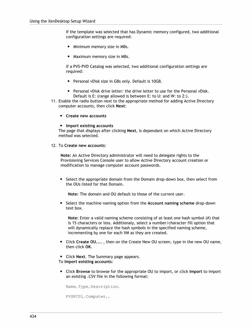
If the template was selected that has Dynamic memory configured, two additionalconfiguration settings are required:
● Minimum memory size in MBs.
● Maximum memory size in MBs.
If a PVS-PVD Catalog was selected, two additional configuration settings arerequired:
● Personal vDisk size in GBs only. Default is 10GB.
● Personal vDisk drive letter: the drive letter to use for the Personal vDisk.Default is E: (range allowed is between E: to U: and W: to Z:).
11. Enable the radio button next to the appropriate method for adding Active Directorycomputer accounts, then click Next:
● Create new accounts
● Import existing accountsThe page that displays after clicking Next, is dependant on which Active Directorymethod was selected.
12. To Create new accounts:
Note: An Active Directory administrator will need to delegate rights to theProvisioning Services Console user to allow Active Directory account creation ormodification to manage computer account passwords.
● Select the appropriate domain from the Domain drop-down box, then select fromthe OUs listed for that Domain.
Note: The domain and OU default to those of the current user.
● Select the machine naming option from the Account naming scheme drop-downtext box.
Note: Enter a valid naming scheme consisting of at least one hash symbol (#) thatis 15 characters or less. Additionaly, select a number/character fill option thatwill dynamically replace the hash symbols in the specified naming scheme,incrementing by one for each VM as they are created.
● Click Create OU.... , then on the Create New OU screen, type in the new OU name,then click OK.
● Click Next. The Summary page appears.To Import existing accounts:
● Click Browse to browse for the appropriate OU to import, or click Import to importan existing .CSV file in the following format:
Name,Type,Description,
PVSPC01,Computer,,
Using the XenDesktop Setup Wizard
434
Note: The Required count displays the number of VMs previously specified.Added count displays the number of entries in the list.
Note: If the machine account 'names' that are being importing already exist inany of the following locations, they are not valid and will not be displayed in thelist; XenDesktop (as a machine), PVS (as a device), on the hypervisor (as a VM). Ifthe AD structure contains a large number of objects/containers and/or you areimporting a large amount of machine accounts, the import may take a while as itmust validate the each account imported does not already exist in PVS, XD andthe destination hypervisor. However if this is the case, you should receivefeedback in the form of an hour glass cursor while the import is being completed.
13. Click Next. The Summary page appears.
14. Review all configuration settings, then click Finish to confirm and perform thefollowing actions, one at a time, across all hosts until configurations are complete:
● If applicable, create XenDesktop Broker Catalog.
● Clone the VM from the template.
● If using a Streamed with personal vDisk catalog, create a personal vDisk.
● If using a Streamed with personal vDisk catalog, attach the personal vDisk to thevirtual machine.
● Create a Provisioning Services Target Device, and assign the selected vDisk.
● Add the Target Device to the selected Collection.
● Add the VM to the Catalog.15. Click Finish after the Progress bar displays that the setup is complete.
Note: Clicking Cancel cancels the configuration of any additional machines, and thequantity of successfully configured machines displays under the Progress bar.
If the wizard fails or is cancelled in the middle of an operation, any progress made isretained. If cleanup of existing progress is required, it must be done manually. Thisinvolves deleting the following:
● XenDesktop machines from the assigned catalog
● Newly created XenDesktop catalogs
● Provisioning Services devices created in the selected collection
● VMs created in any of the selected hosts hypervisors
● Active Directory computer accounts that were created
Using the XenDesktop Setup Wizard
435
436
Logging
Provisioning Services provides logging to help with troubleshooting and managing aProvisioning Services farm.
All log file settings can be managed from the Provisioning Services’ Console. Settings aresaved to the database as properties that are specific to each Provisioning Server or targetdevice.
Logging includes:
“Configuring Provisioning Server Log File Properties”
Configuring Target Device Log File Properties
Managing Log Files and Locations
437
Configuring Provisioning Server LogProperties
Provisioning Server properties include:
● Level of logging (as described in the procedure that follows)
● Maximum size of the log file (MB)
● Maximum number of log file backup copies to retain
To edit a Provisioning Server’s log properties
Note: Changes to target device log properties are immediate. Changes to Server logproperties may take up to ninety seconds to take effect.
1. In the Console, right-click on the Provisioning Server, then select the Properties menuoption.
2. On the Logging tab, select one of the following logging levels (Note: The logging levelsthat follow are listed from the minimum level to the maximum level of logginginformation that can be collected Logging levels are inclusive of previous levels. Forexample, if you select INFO, log information will include WARN, ERROR, and FATAL):
● OFF
Logging is disabled for this Provisioning Server.
● FATAL
The FATAL level logs information about an operation that the system could notrecover from.
● ERROR
The ERROR level logs information about an operation that produces an errorcondition.
WARN● WARN
The WARNING level logs information about an operation that completessuccessfully, but there are issues with the operation.
● INFO
Default logging level. The INFO level logs information about workflow, whichgenerally explains how operations occur.
● DEBUG
The DEBUG level logs details related to a specific operation and is the highest levelof logging. If logging is set to DEBUG, all other levels of logging information aredisplayed in the log file.
● TRACE
TRACE logs all valid operations.
3. In the Max File Size text box, scroll to select the maximum size that a log file canreach. When the max file size is reached, the file is closed and an index number isappended to the file name, then a new file is created.
4. In the Max Backup Files text box, scroll to select the maximum number of backup filesto retain, then click OK. The oldest log file is automatically deleted when the maximumnumber of backup files is reached.
5. On the General tab, enable Log events to the server’s Windows Event Log to allow forlogging events using the Windows Event log on the Provisioning Server that iscommunicating with this target device. This log includes errors that may occur after theearly boot phase as well as any critical error reporting. Click OK.
Note: Provisioning Server logging levels should not be set by modifying theStreamProcess_log.config file manually (refer to “Log Files and Locations”) because itmay cause the logging level to be out of sync.
Configuring Provisioning Server Log Properties
438
439
Configuring Target Device Log Properties
Target device logging should only be turned on if there are issues with the device; loggingon the device is dependant on logging being enabled on the Provisioning Server. Logginginformation is sent back to the Provisioning server and written to its log file.
Target device log properties include setting the level of logging on the target device.
To edit a target device’s log properties
1. In the Console, right-click on the target device, then select the Properties menuoption.
2. On the Logging tab, select one of the following options:
● OFF
Logging is disabled for this target device.
● FATAL
The FATAL level logs information about an operation that the system could notrecover from.
● ERROR
The ERROR level logs information about an operation that produces an errorcondition.
● WARN
The WARNING level logs information about an operation that completessuccessfully, but there are issues with the operation.
● INFO
Default logging level. The INFO level logs information about workflow, whichgenerally explains how operations occur.
● DEBUG
DEBUG logs all system level activity.
● TRACE
TRACE logs all valid operations.
440
Log Files and Content
This sections describes how to locate log files and identifies the types of information thelog file contains.
● Log File Location
● Log File Content
Log File LocationFiles used to manage logging and any generated log files are located in:%APPDATA%\Citrix\Provisioning Services\logs
For example:
C:\Documents and Settings\All Users\Application Data\Citrix\Provisioning Services\logs
Log files include:
Stream_log.config
Note: This file should not be edited manually. Logging levels should be set through theConsole. Any edits made to this file manually are lost when the Provisioning Serverrestarts, or when logging levels are changed using the Console.
Stream.log
StreamProcess.exe, StreamProcess.exe, Manager.dll,
and Streamdb.dll all write to the Stream.log file.
MCLI.log
MCLI.exe writes MCLI logging information to MCLI.log
SoapServer.log
SoapServer.exe writes SoapServer logging information to SoapServer.log
Console.log
Console.exe writes Console logging information to Console.log
ConfigWizard.log
ConfigWizard.exe writes Provisioning Server configuration logging information toConfigWizard.log
Log File ContentsThe content of a log file includes:
● Timestamp
● Logging Level
● Component and method used to perform logging
● Provisioning Server and target device identity (name, IP, or MAC)
● Logging message with supporting data of Windows error codes when appropriate
Log Files and Content
441
442
Auditing
Provisioning Services provides an auditing tool that records configuration actions oncomponents within the Provisioning Services farm, to the Provisioning Services database.This provides administrators with a way to troubleshoot and monitor recent changes thatmight impact system performance and behavior.
The Provisioning Services administrator privileges determines the audit information that canbe viewed and the menu options that are visible. For example; a Farm Administrator canview all audit information within the farm, unlike a Device Administrator whom can onlyview audit information for those device collections they have privileges to.
Auditing tasks include:
● Enabling Auditing
● Accessing Auditing
● Archiving Audit Trail Information
Note: Auditing is off by default. Also, if the Provisioning Services database becomesunavailable, no actions are recorded.
The managed objects within a Provisioning Services implementation that are auditedinclude:
● Farm
● Site
● Provisioning Servers
● Collection
● Device
● Store
● vDisks
Only those tasks that are performed from one of the following Provisioning Services utilitiesare recorded:
● Console
● MCLI
● SOAP Server
● PowerShell

Note: Tasks that are not performed using these utilities, such as booting target devices orProvisioning Servers by other methods, are not recorded. If the Provisioning Servicesdatabase becomes unavailable, no actions are recorded.
Auditing
443
444
Enabling Auditing Information
The auditing feature is disabled by default. To enable auditing:
1. In the Console tree, right-click on the farm, then select the farm Properties menuoption.
2. On the Options tab, under Auditing, check the Enable auditing checkbox.
445
Accessing Auditing Information
Auditing information is accessed using the Console or using one of the followingprogramming utilities:
● MAPI (refer to the MAPI Programming Guide)
● PowerShell (refer to the PowerShell Programming Guide)
● SOAP Server (refer to the SOAP Server Programming Guide)
In the Console, a farm administrator can right-click on a parent or child node in the Consoletree to access audit information. The audit information that other administrators canaccess depends on the role they were assigned.
The tree allows for a drill-down approach when accessing the level of audit informationneeded.
Right-click on a:
● Farm, to view audit information for all managed objects within this farm or to archiveaudit information.
● Site, to view audit information for all managed objects within a site.
● Provisioning Server, to view audit information for all servers within a site, orright-click on a single server to view audit information for that server.
● Collection, to view audit information on all managed objects that are members of thiscollection.
● Store, to view audit information for all stores within a site or farm, or right-click on asingle store to view audit information for that store.
● Target device, to view audit information for all target devices within a site, orright-click on a single target device to view audit information for that device.
● vDisk, to view audit information for all vDisks within a site or farm, or right-click on asingle vDisk to view audit information for that vDisk.
To access auditing information from the Console
1. In the Console, right-click on a managed object, then select the Audit Trail... menuoption. The Audit Trail dialog displays or a message appears indicating that no auditinformation is available for the selected object.
2. Under Filter Results, select from the following filter options:
Option Description
User To narrow the resulting auditinformation that displays by user, selecta user to filter on from the Userdrop-down menu. The default is Allusers.
Domain To narrow the resulting auditinformation that displays by domains,select a domain to filter on from theDomain drop-down menu. The default isAll domains.
Start date To narrow the resulting auditinformation that displays by date, selecta start date for which the auditinformation should display from the Startdate drop-down menu. The default is oneweek prior to the current date. Forexample, if today is the 23rd, the startdate would default to the 16th.
End date To narrow the resulting auditinformation that displays by date, selectan end date for which the auditinformation should display from the Enddate drop-down menu. The default is thecurrent date.
Action To narrow the resulting auditinformation that displays by the action,such as Set Disklocator, select the actionfrom the Action drop-down menu. Thedefault is to display all actions.
Type To narrow the resulting auditinformation that displays by the type ofaction, such as Disklocator, select thetype from the Type drop-down menu.The default is to display all types.
3. Click Search. The resulting audit information displays in the audit table, which displaysthe following information:
Note: Columns in the audit table can be sorted in ascending and descending order byclicking on the column heading.
● Action list number
Based on the filter criteria selected, the order the actions took place.
● Date/Time
Lists all audit actions that occurred within the Start date and End date filtercriteria.
● Action
Identifies the name of the Provisioning Services action taken.
Accessing Auditing Information
446
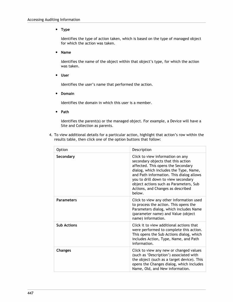
● Type
Identifies the type of action taken, which is based on the type of managed objectfor which the action was taken.
● Name
Identifies the name of the object within that object’s type, for which the actionwas taken.
● User
Identifies the user’s name that performed the action.
● Domain
Identifies the domain in which this user is a member.
● Path
Identifies the parent(s) or the managed object. For example, a Device will have aSite and Collection as parents.
4. To view additional details for a particular action, highlight that action’s row within theresults table, then click one of the option buttons that follow:
Option Description
Secondary Click to view information on anysecondary objects that this actionaffected. This opens the Secondarydialog, which includes the Type, Name,and Path information. This dialog allowsyou to drill down to view secondaryobject actions such as Parameters, SubActions, and Changes as describedbelow.
Parameters Click to view any other information usedto process the action. This opens theParameters dialog, which includes Name(parameter name) and Value (objectname) information.
Sub Actions Click it to view additional actions thatwere performed to complete this action.This opens the Sub Actions dialog, whichincludes Action, Type, Name, and Pathinformation.
Changes Click to view any new or changed values(such as ‘Description’) associated withthe object (such as a target device). Thisopens the Changes dialog, which includesName, Old, and New information.
Accessing Auditing Information
447

Note: If an option displays disabled, that option is not valid for the currently selectedaction.
Accessing Auditing Information
448

449
Archiving Audit Trail Information
The Farm Administrator determines how long to make audit trail information accessiblebefore it is archived.
To set audit trail archiving
1. In the Console tree, right-click on the farm, then select Archive Audit Trail.... TheArchive Audit Trail dialog appears.
2. Browse for the location where audit trail information will be save (XML file). The SelectFile to Archive Audit Trail To dialog opens.
3. Select the location, then type the name of the new file in the File name textbox.
4. Open the calendar from the End date drop-down menu, then select the date that theaudit trail information should be archived. The default is automatically set to thecurrent date.
5. Check the Remove information archived from the Audit Trail checkbox to remove allaudit information. Once the information is removed, it can no longer be accesseddirectly from Provisioning Services. It will only exist in the XML file.
6. Click OK.
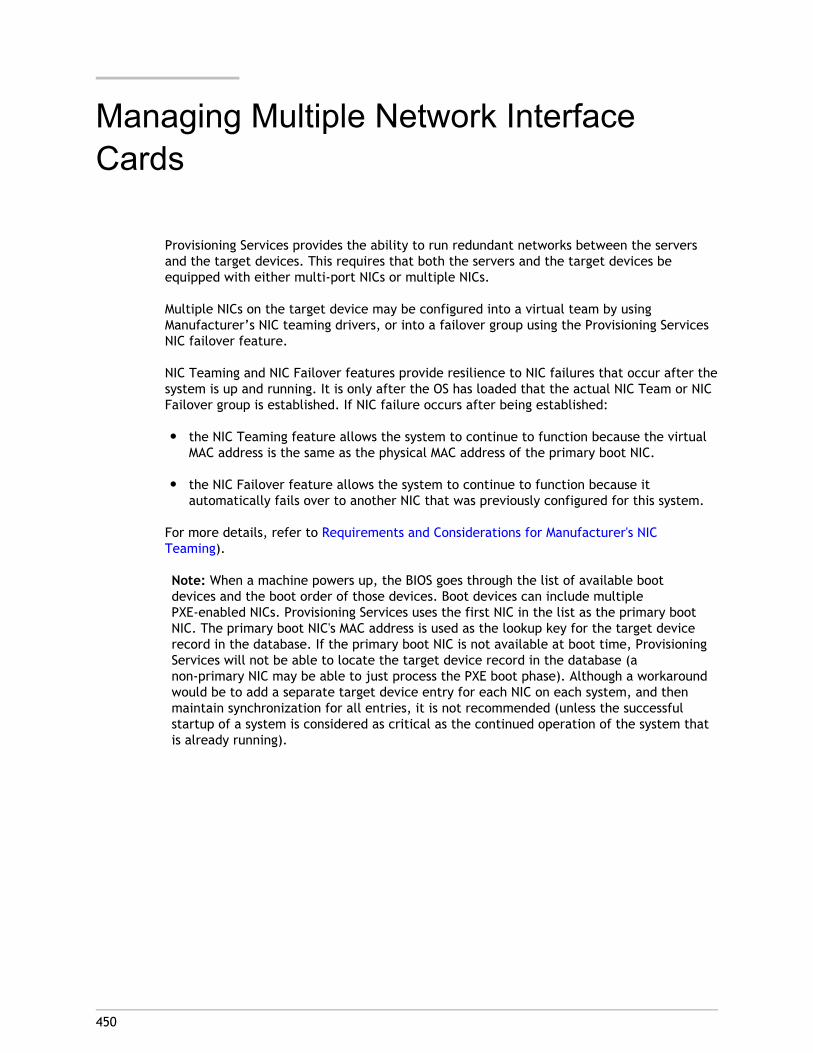
450
Managing Multiple Network InterfaceCards
Provisioning Services provides the ability to run redundant networks between the serversand the target devices. This requires that both the servers and the target devices beequipped with either multi-port NICs or multiple NICs.
Multiple NICs on the target device may be configured into a virtual team by usingManufacturer’s NIC teaming drivers, or into a failover group using the Provisioning ServicesNIC failover feature.
NIC Teaming and NIC Failover features provide resilience to NIC failures that occur after thesystem is up and running. It is only after the OS has loaded that the actual NIC Team or NICFailover group is established. If NIC failure occurs after being established:
● the NIC Teaming feature allows the system to continue to function because the virtualMAC address is the same as the physical MAC address of the primary boot NIC.
● the NIC Failover feature allows the system to continue to function because itautomatically fails over to another NIC that was previously configured for this system.
For more details, refer to Requirements and Considerations for Manufacturer's NICTeaming).
Note: When a machine powers up, the BIOS goes through the list of available bootdevices and the boot order of those devices. Boot devices can include multiplePXE-enabled NICs. Provisioning Services uses the first NIC in the list as the primary bootNIC. The primary boot NIC's MAC address is used as the lookup key for the target devicerecord in the database. If the primary boot NIC is not available at boot time, ProvisioningServices will not be able to locate the target device record in the database (anon-primary NIC may be able to just process the PXE boot phase). Although a workaroundwould be to add a separate target device entry for each NIC on each system, and thenmaintain synchronization for all entries, it is not recommended (unless the successfulstartup of a system is considered as critical as the continued operation of the system thatis already running).
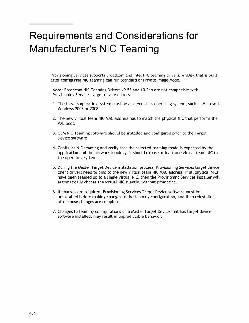
451
Requirements and Considerations forManufacturer's NIC Teaming
Provisioning Services supports Broadcom and Intel NIC teaming drivers. A vDisk that is builtafter configuring NIC teaming can run Standard or Private Image Mode.
Note: Broadcom NIC Teaming Drivers v9.52 and 10.24b are not compatible withProvisioning Services target device drivers.
1. The targets operating system must be a server-class operating system, such as MicrosoftWindows 2003 or 2008.
2. The new virtual team NIC MAC address has to match the physical NIC that performs thePXE boot.
3. OEM NIC Teaming software should be installed and configured prior to the TargetDevice software.
4. Configure NIC teaming and verify that the selected teaming mode is expected by theapplication and the network topology. It should expose at least one virtual team NIC tothe operating system.
5. During the Master Target Device installation process, Provisioning Services target deviceclient drivers need to bind to the new virtual team NIC MAC address. If all physical NICshave been teamed up to a single virtual NIC, then the Provisioning Services installer willautomatically choose the virtual NIC silently, without prompting.
6. If changes are required, Provisioning Services Target Device software must beuninstalled before making changes to the teaming configuration, and then reinstalledafter those changes are complete.
7. Changes to teaming configurations on a Master Target Device that has target devicesoftware installed, may result in unpredictable behavior.
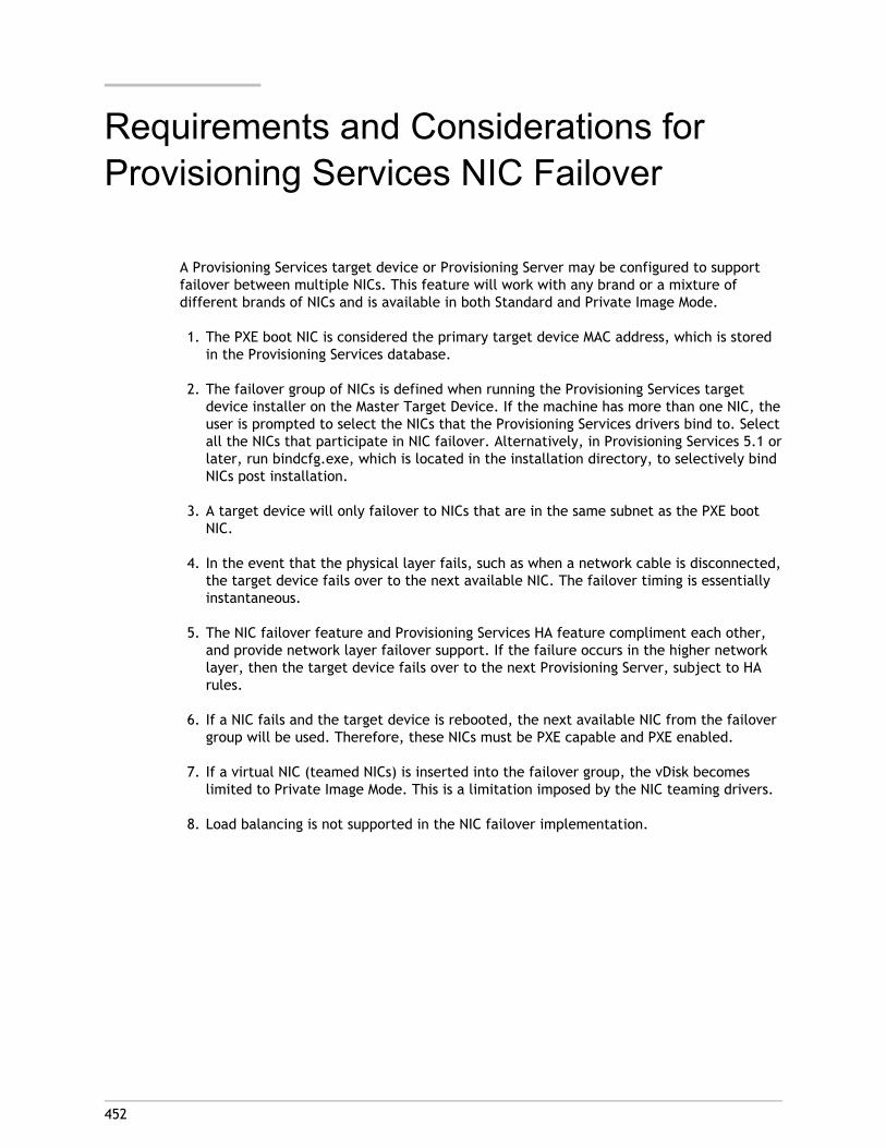
452
Requirements and Considerations forProvisioning Services NIC Failover
A Provisioning Services target device or Provisioning Server may be configured to supportfailover between multiple NICs. This feature will work with any brand or a mixture ofdifferent brands of NICs and is available in both Standard and Private Image Mode.
1. The PXE boot NIC is considered the primary target device MAC address, which is storedin the Provisioning Services database.
2. The failover group of NICs is defined when running the Provisioning Services targetdevice installer on the Master Target Device. If the machine has more than one NIC, theuser is prompted to select the NICs that the Provisioning Services drivers bind to. Selectall the NICs that participate in NIC failover. Alternatively, in Provisioning Services 5.1 orlater, run bindcfg.exe, which is located in the installation directory, to selectively bindNICs post installation.
3. A target device will only failover to NICs that are in the same subnet as the PXE bootNIC.
4. In the event that the physical layer fails, such as when a network cable is disconnected,the target device fails over to the next available NIC. The failover timing is essentiallyinstantaneous.
5. The NIC failover feature and Provisioning Services HA feature compliment each other,and provide network layer failover support. If the failure occurs in the higher networklayer, then the target device fails over to the next Provisioning Server, subject to HArules.
6. If a NIC fails and the target device is rebooted, the next available NIC from the failovergroup will be used. Therefore, these NICs must be PXE capable and PXE enabled.
7. If a virtual NIC (teamed NICs) is inserted into the failover group, the vDisk becomeslimited to Private Image Mode. This is a limitation imposed by the NIC teaming drivers.
8. Load balancing is not supported in the NIC failover implementation.
453
Glossary
AutoUpdate
A command-line utility that is used to create a delta file when incrementally updating avDisk.
Boot Device Manager (BDM)
A utility used to create boot devices that have the bootstrap and IP informationpre-installed; enabling a target device to boot over the network without the use of PXEor DHCP.
Boot Services
A set of network boot services that can be used to get the boot information necessarywhen booting a target device from a vDisk, including PXE, TFTP, and BOOTP.
BOOTP
An IP/UDP bootstrap protocol (BOOTP), which allows a target device to discover its IPaddress and other IP configuration parameters.
BOOTPTAB
BOOTPTAB is the backend table that maps a target devices MAC addres to the IP addressassigned by the administrator.
Common Image Feature
A feature that allows a single vDisk image to work for target devices using networkinterface cards that vary.
Device Administrator
Device Administrators manage device collections within a site.
Device Collection
A logical grouping of devices. For example, a device collection could represent a physicallocation, a subnet range and a logical grouping of target devices. A target device canonly belong to one device collection.
Device Operator
Device Operators can view the properties of vDisks and target devices and, boot or shutdown target devices within a device collection.
Disk Store (Store)
A logical name given to a physical storage location for vDisks. The store is used by one ormore Provisioning Servers within a farm to refer to a shared storage location.
vDisk Pool
The collection of all vDisks available to a site. There is one vDisk pool per site.
Domain
An Active Directory domain as defined by Microsoft.
Dynamic Host Configuration Protocol (DHCP)
A protocol used for assigning IP addresses and other IP parameters to devices on anetwork.
EULA
End-User License Agreement.
Farm Administrator
A farm administrator can view and manage all objects within a farm. Farm administratorscan also create new sites and manage role memberships throughout the entire farm.
High Availability Feature (HA)
A Provisioning Services environment in which at least one Provisioning Server isconfigured as a backup should the primary Provisioning Server fail for any reason. If theconnection between a targetdevice and a Provisioning Server is lost and HA is enabled,the connection will failover to the secondary Provisioning Server.
IPSEC
Internet Protocol Security.
Master Target Device
A target device that has Provisioning Services device software installed, and from whicha hard disk image is built and stored on a vDisk. Provisioning Services then streams thecontents of the vDisk created from the Master Target Device to other target devices ondemand.
MMC
The acronym for Microsoft Management Console.
Optimization Utility
A command-line utility used to apply several settings to your hard drive or vDisk, thatconfigures Windows to perform at optimal performance when running from a vDisk.
Preboot Execution Environment (PXE) Service
An optional software service that can deliver the boot file name and location to targetdevices.
Glossary
454
Provisioning Services Console (Console)
A management console utility used to manage configuration settings for target devices,Provisioning Servers, and vDisks.
Provisioning Services database (database)
Repository of configuration settings for Provisioning Servers, target devices, and vDisks.
Provisioning Services Farm (farm)
A group of Provisioning Servers that share the same database.
Role
A set of defined permissions that can be assigned to a farm, site, and collection.
Role Based Administration
The method of administration that limits the administer’s management permissions tothose defined in the assigned role.
Site
A container that groups a vDisk Pool, Provisioning Servers and Device Collections. A sitecan represent a physical or logical location.
Store
A store is the logical name for the physical location of the vDisk folder that can exist ona local server or on shared storage.
Stream Service
The software service that transfers software between a target device, its vDisk, andwrite cache.
Target Device
A device, such as a desktop computer or server, that boots and gets software from avDisk on the network, by communicating with a Provisioning Server.
Target Device Optimization Utility
A command-line utility used to apply several settings to your hard drive or vDisk that,when used, configures Windows to perform at optimal performance when running from avDisk.
User Datagram Protocol (UDP)
The primary protocol used by Provisioning Servers.
User Groups
User groups provide Farm and Site Administrators with the ability to create and managegroups of users based on existing Active Directory or Windows groups.
Glossary
455
View
A logical grouping of target devices within a farm or site, for the purpose of simplifydevice administration. A view can represent target devices spread across multiple sitesand device collections. A target device can belong to any
Virtual Disk (vDisk)
A file that is accessible to a Provisioning Server and is used to emulate a hard drive for atarget device.
Write Cache Mode
The cache option selected to store a target device’s disk writes when using awrite-protected vDisk. The write cache can reside on the Provisioning Server, on sharedstorage, in the target device’s RAM, or on the target device’s local hard drive.
Glossary
456