prototype ku-band dual polarization siw monopulse...
TRANSCRIPT

Prototype Ku-Band Dual Polarization SIW
Monopulse Antenna
Dong-yeon Kim, Sangwook Nam
The Institute of New Media Communication (INMC),
School of Electrical Engineering and Computer Science,
Seoul National Univ. Seoul 151-742, Korea
Chang-Hyun Park, Bae-Ho Jeong
LIG Nex1 Co., Ltd.,
Yongin-si 446-798, Korea
Abstract—In this paper, a prototype slot array antenna for
dual polarized monopulse operation is proposed. The suggested
monopulse antenna structure is composed of a dual polarized
radiating part using substrate integrated waveguide (SIW)
technology and a feed network using metallic rectangular
waveguides for dual plane tracking. Radiation patterns of the
fabricated prototype antenna are measured at elevation and
azimuth cutting planes for each linear polarization. Measured
realized sum (Σ) pattern gains are more than 22 dBi and the null
depths (NDs) for difference (Δ) patterns are less than ‒27 dB at
boresight direction at center frequency of Ku-band. However, the
proposed prototype monopulse antenna has somewhat high
sidelobe and cross polarization levels. The reasons for these
drawbacks are discussed at the end of this paper.
Keywords—comparator, dual polarization, monopulse antenna,
SIW, slot array antenna
I. INTRODUCTION
Monopulse radar systems are commonly used to find target direction using reflected waves [1], and therefore the radiators and the feed networks are the most important parts of the system. The conventional monopulse antennas were heavy and complicated like Cassegrain parabolic antennas [1]. In order to realize lightweight and low-profile structure, the slotted waveguide array antennas were developed and used with high radiating efficiency. Recently, a number of researches suggest the applied substrate integrated waveguide (SIW) structures for lightweight feature [2, 3]. The 2-dimensional (2-D) monopulse antennas were developed using SIW shunt radiating slots for Ka- and W-band [2, 3]. Meanwhile, the dual polarization in monopulse systems is required for high channel capacity. In [4], series and shunt radiating slots are arrayed on narrow wall waveguides and ridged waveguides, respectively, to reduce sidelobe levels (SLLs) and cross polarization levels, simultaneously. In [5], the dual polarization is realized with interlaced and ±45°-inclined slot arrays for low cross polarization levels.
In this paper, dual polarization is realized by ±45°-inclined SIW series slot radiators using [6] suggested by authors for lightweight and low-profile features. Whole radiators can be embedded in printed circuit boards (PCBs) using standard PCB process. The whole systems are designed with commercial software CST MWS [7] and the fabricated prototype antenna
was experimented in terms of reflection coefficients, realized gain, and radiation patterns for each polarization.
II. PROPOSED PROTOTYPE MONOPULSE ANTENNA
The proposed prototype antenna structure is shown in Fig. 1. Target antenna sum gain is 20 dBi with the given aperture
(a)
(b)
Fig. 1. The proposed prototype dual polarized SIW monopulse antenna. (a)
Top view. (b) Bottom view (Two comparators for each linear polarization
are connected to SIW input ports with rigid cables)
565
2014 3rd Asia-Pacific Conference on Antennas and Propagation
978-1-4799-4355-5/14/$31.00 ©2014 IEEE Harbin, CHINA
diameter of 220 mm for Ku-band. In addition, dual linear polarizations are required within a common aperture area at the same operation frequency. In order to suppress SLLs and realize dual polarization, simultaneously, the 45°-inclined SIW series slot array antenna [6] is employed as shown in Fig. 1(a). Total 16 × 10 radiating slots for each polarization are divided into four 8 × 5 sub-arrays in each sub-quadrant. And each four sub-arrays are fed by each two comparators for dual polarized monopulse operation as shown in Fig. 1(b).
A. SIW Radiators for Dual Polarization
The width and relative dielectric constant of the radiating SIW are 8.0 mm and 3.5, respectively, and corresponding one guided-wavelength is 13.4 mm at the center frequency (fc). A linear slot array antenna is designed with eight series radiating slots with a half guided-wavelength spacing (= 0.36·λ0) of the given radiating SIW. A sub-array is composed with five identical linear slot arrays that are separated by a guided-wavelength of a feeding SIW as shown in Fig. 2. In addition, cross-polarized linear slot arrays are located between co-polarized linear slot arrays for dual polarization. Every linear slot array is fed by series-to-series coupling slots with same length and tilt angle for uniform power distribution as shown in Fig. 2(b). Moreover, these four dual polarized sub-arrays are located at each sub-quadrant for dual plane monopulse operation as shown in Fig. 1(a).
B. Feed Network (Comparator)
Dual plane (azimuth and elevation directions) monopulse operation is possible with a sum (Σ) and two difference (ΔEL, ΔAZ) patterns using three Magic-Ts with a T-junction as shown in Fig. 3. Also, a duplicated feed network is symmetrically located for dual polarization. Each four output ports of a feed network (i.e., port 1~4 in Fig. 3) are connected to the input ports of each co-polarized sub-arrays using rigid cables that have same electrical length for phase balance. As a result, total prototype dual polarized monopulse antenna has six input ports as shown in Fig. 1(b).
III. PERFORMANCES
The proposed monopulse antenna is measured and verified with reflection coefficients, realized gains, and radiation patterns (i.e., SLLs, cross polarization levels for sum patterns and null depth (ND) for difference patterns, respectively). The experiment was done with an E8361A network analyzer from Agilent. In addition, the radiation pattern measurement was conducted in an anechoic chamber.
A. Reflection Coefficients
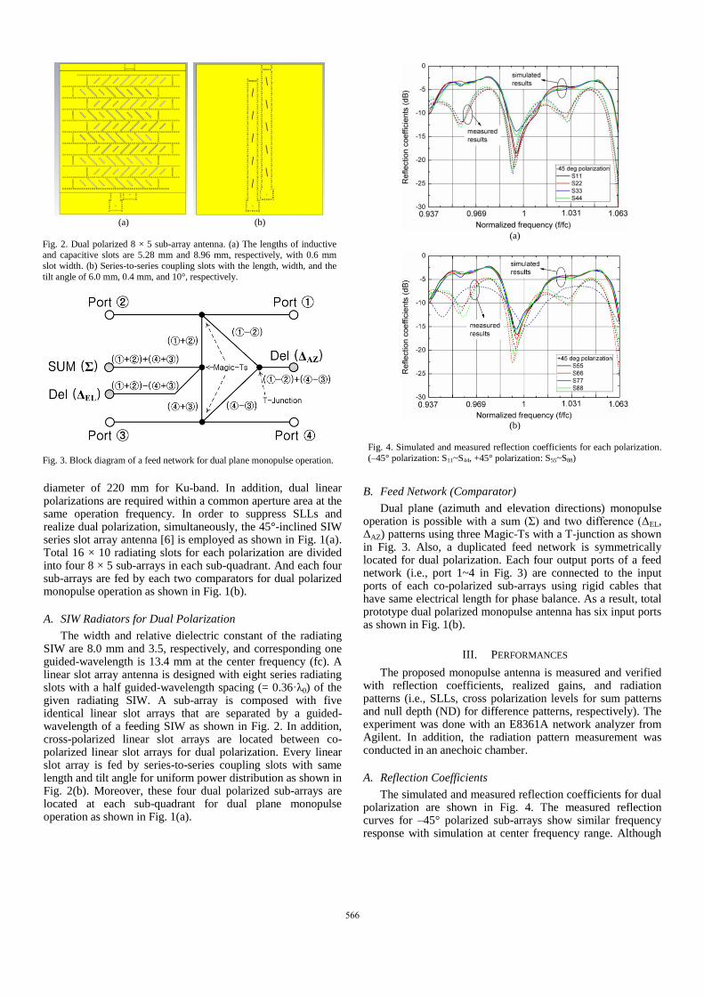
The simulated and measured reflection coefficients for dual polarization are shown in Fig. 4. The measured reflection curves for –45° polarized sub-arrays show similar frequency response with simulation at center frequency range. Although
(a) (b)
Fig. 2. Dual polarized 8 × 5 sub-array antenna. (a) The lengths of inductive and capacitive slots are 5.28 mm and 8.96 mm, respectively, with 0.6 mm
slot width. (b) Series-to-series coupling slots with the length, width, and the
tilt angle of 6.0 mm, 0.4 mm, and 10°, respectively.
Fig. 3. Block diagram of a feed network for dual plane monopulse operation.
(a)
(b)
Fig. 4. Simulated and measured reflection coefficients for each polarization.
(–45° polarization: S11~S44, +45° polarization: S55~S88)
566

the measured reflection curve at port 7 is different with other responses as shown in Fig. 4(b), the operating frequency range is not changed.
B. Radiation Characteristics
The radiation patterns are measured and normalized for each dual linear polarization at Fmin, Fc, and Fmax in Ku-band. The SLLs for azimuth plane are higher than expected levels of –13.5 dB derived from uniform field distribution as shown in Fig. 5(a) and 6(a). It is considered that the increased SLLs for azimuth plane are due to the slot free region (or blockage with 0.75·λ0 spacing) between sub-array 1, 4 and sub-array 2, 3 as depicted in Fig. 1(a). Meanwhile, the realized gains of sum patterns are verified with 22.12 and 22.25 dBi for –45° and +45° polarization, respectively, at center frequency. The measured gains are lower than simulated results about –2 dB due to the insertion losses generated by a comparator (i.e. about –1 dB) and rigid cables (i.e. about –1 dB). Meanwhile, the cross polarizations are detected with considerable levels about –7 dB at boresight direction.
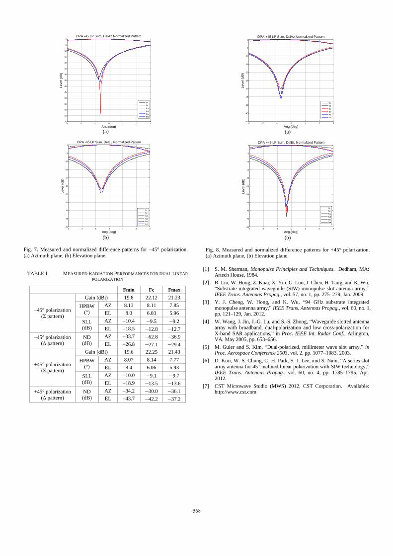
Another essential design parameter for monopulse system is ND for difference patterns. In general, the deeper ND at boresight direction, the more accurate angle detection can be guaranteed [1]. In addition, the symmetrical difference patterns can be developed by balanced amplitude and phase output from feed networks. The measured difference patterns are depicted
in Fig. 7 and 8 for each polarization, respectively. For –45° polarization, the deepest ND is measured with –62.8 dB at –0.7° from z-axis and remaining NDs are better than –25 dB. In addition, for +45° polarization, the deepest ND is measured with –43.7 dB at –0.3° from z-axis and remaining NDs are better than –30 dB. The detailed values for radiation characteristics are summarized in TABLE I.
IV. DRAWBACKS AND CONCLUSIONS
The prototype of ±45° dual polarized monopulse antenna for Ku-band was developed using a SIW radiator with metallic waveguide feed networks as a hybrid structure. The realized sum pattern gains were measured more than 20 dBi. In addition, the sufficient null depths were obtained for dual polarization and under the operating bandwidth. On the other hand, there were several drawbacks in radiation performances such as SLLs and cross polarization levels for sum patterns. The slot free region at boundary between sub-arrays caused increased SLLs. In addition, the orthogonal coordinate system is required for the suppressed cross polarization levels between ±45° inclined radiating slots.
ACKNOWLEDGMENT
This work was supported by LIG Nex1 Co. LTD.
REFERENCES
-80 -60 -40 -20 0 20 40 60 80-70
-60
-50
-40
-30
-20
-10
0
Ang.(deg)
Le
ve
l (d
B)
DPA +45 LP (Phi 0 cut) Pattern
Fmin
Fc
Fmax
(a)
-80 -60 -40 -20 0 20 40 60 80-70
-60
-50
-40
-30
-20
-10
0
Ang.(deg)L
eve
l (d
B)
DPA +45 LP (Phi 90 cut) Pattern
Fmin
Fc
Fmax
(b)
Fig. 6. Measured radiation patterns for +45° polarization. (a) Azimuth plane,
(b) Elevation plane.
-80 -60 -40 -20 0 20 40 60 80-70
-60
-50
-40
-30
-20
-10
0
Ang.(deg)
Le
ve
l (d
B)
DPA -45 LP (Phi 0 cut) Pattern
Fmin
Fc
Fmax
(a)
-80 -60 -40 -20 0 20 40 60 80-70
-60
-50
-40
-30
-20
-10
0
Ang.(deg)
Le
ve
l (d
B)
DPA -45 LP (Phi 90 cut) Pattern
Fmin
Fc
Fmax
(b)
Fig. 5. Measured radiation patterns for –45° polarization. (a) Azimuth plane,
(b) Elevation plane.
567
[1] S. M. Sherman, Monopulse Principles and Techniques. Dedham, MA: Artech House, 1984.
[2] B. Liu, W. Hong, Z. Kuai, X. Yin, G. Luo, J. Chen, H. Tang, and K. Wu, “Substrate integrated waveguide (SIW) monopulse slot antenna array,” IEEE Trans. Antennas Propag., vol. 57, no. 1, pp. 275–279, Jan. 2009.
[3] Y. J. Cheng, W. Hong, and K. Wu, “94 GHz substrate integrated monopulse antenna array,” IEEE Trans. Antennas Propag., vol. 60, no. 1, pp. 121–129, Jan. 2012.
[4] W. Wang, J. Jin, J.-G. Lu, and S.-S. Zhong, “Waveguide slotted antenna array with broadband, dual-polarization and low cross-polarization for X-band SAR applications,” in Proc. IEEE Int. Radar Conf., Arlington, VA. May 2005, pp. 653–656.
[5] M. Guler and S. Kim, “Dual-polarized, millimeter wave slot array,” in Proc. Aerospace Conference 2003, vol. 2, pp. 1077–1083, 2003.
[6] D. Kim, W.-S. Chung, C.-H. Park, S.-J. Lee, and S. Nam, “A series slot array antenna for 45º-inclined linear polarization with SIW technology,” IEEE Trans. Antennas Propag., vol. 60, no. 4, pp. 1785–1795, Apr. 2012.
[7] CST Microwave Studio (MWS) 2012, CST Corporation. Available: http://www.cst.com
TABLE I. MEASURED RADIATION PERFORMANCES FOR DUAL LINEAR
POLARIZATION
Fmin Fc Fmax
–45° polarization
(Σ pattern)
Gain (dBi) 19.8 22.12 21.23
HPBW
(°)
AZ 8.13 8.11 7.85
EL 8.0 6.03 5.96
SLL
(dB)
AZ –10.4 –9.5 –9.2
EL –18.5 –12.8 –12.7
–45° polarization (Δ pattern)
ND (dB)
AZ –33.7 –62.8 –36.9
EL –26.8 –27.1 –29.4
+45° polarization
(Σ pattern)
Gain (dBi) 19.6 22.25 21.43
HPBW
(°)
AZ 8.07 8.14 7.77
EL 8.4 6.06 5.93
SLL
(dB)
AZ –10.0 –9.1 –9.7
EL –18.9 –13.5 –13.6
+45° polarization
(Δ pattern)
ND
(dB)
AZ –34.2 –30.0 –36.1
EL –43.7 –42.2 –37.2
-3 -2 -1 0 1 2 3-70
-65
-60
-55
-50
-45
-40
-35
-30
-25
-20
-15
-10
-5
0
Ang.(deg)
Level (d
B)
DPA -45 LP Sum, DelAz Normalized Pattern
fls
fld
fcs
fcd
fhs
fhd
(a)
-3 -2 -1 0 1 2 3-50
-45
-40
-35
-30
-25
-20
-15
-10
-5
0
Ang.(deg)
Level (d
B)
DPA -45 LP Sum, DelEL Normalized Pattern
fls
fld
fcs
fcd
fhs
fhd
(b)
Fig. 7. Measured and normalized difference patterns for –45° polarization.
(a) Azimuth plane, (b) Elevation plane.
-3 -2 -1 0 1 2 3-50
-45
-40
-35
-30
-25
-20
-15
-10
-5
0
Ang.(deg)
Level (d
B)
DPA +45 LP Sum, DelAz Normalized Pattern
fls
fld
fcs
fcd
fhs
fhd
(a)
-3 -2 -1 0 1 2 3-50
-45
-40
-35
-30
-25
-20
-15
-10
-5
0
Ang.(deg)
Level (d
B)
DPA +45 LP Sum, DelEL Normalized Pattern
fls
fld
fcs
fcd
fhs
fhd
(b)
Fig. 8. Measured and normalized difference patterns for +45° polarization. (a) Azimuth plane, (b) Elevation plane.
568