a compact simultaneous k/s-band monopulse tracking feed
TRANSCRIPT

A Compact Simultaneous K/S-Band Monopulse Tracking Feed for Future Earth Observation
Applications César Barquinero , Julián Gómez , Angel Mediavilla , José Luis Besada , Belén Galocha
Abstract — This paper presents a novel K/S band monopulse tracking feed for the next generation of Earth Observation (EO) applications in the 25.5 to 27 GHz band. A brief review of the feed, which covers the design and development of a dual band coaxial horn, a TE21 resonant tracking coupler, OMTs and polarizers (septum and corrugated), is included. Characterization of the complete feed in both bands is also summarized in the paper, as well as the evaluation of several dielectric materials for the radome feed window, which is particularly critical in K-band
Keywords — earth observation, coaxial waveguide feed, TE21 monopulse tracking.
I. INTRODUCTION
Currently, EO satellites use the Earth Exploration Satellite (EES) X-band for the download of payload data between 7.75 and 7.90 GHz for meteorological satellites, or between 8.025 and 8.4 GHz for other EO satellites. These missions require data rates in the order of hundreds of megabit per second and it is foreseen that with the future developments in sensing techniques and services this value will reach more than one gigabit per second. Therefore, the present allocated bandwidth at X-Band (i.e. 375 MHz wide for EO and 150 MHz for meteorological satellites), will not be enough to cope with such high data rates of these future missions. In addition, the list of new services provided is expected to grow together with the level of operational requirements, which will lead to congestion of the X-band.
Taking into account the previous scenario, a mitigation of the above problems is the migration of the payload data to the K-band at 25.5-27 GHz, also called the 26 GHz band, which has been allocated to EES services at the ITU World Radio Communications Conference (WRC) [1], The available bandwidth in this new band is four times higher than in the X-band, which represent a major leap in downlink capacity for the next generation of EO satellites. In addition to the reception of the payload data at K-band, the ground stations will need to provide TT&C functionality at S-band, for the reception of telemetry (TM) and transmission of telecommands (TC) to the satellite.
Therefore, new feeds for future Earth Stations need to be developed to allow simultaneous operation at both K and S
bands. Moreover, tracking capabilities have to be added to those feeds in order to correctly follow the trajectory of the EO satellites, typically located at Low and Medium Earth Orbits (LEO/MEO), while minimising the pointing losses. This is especially true at K-band, where the radiation beam-widths are very small for high diameter antennas.
In this work, the selected tracking approach for the developed feed belongs to the monopulse concept. Although this tracking strategy increases the complexity of the feed, as it requires additional ports, it has been selected due to its proven accuracy [2]-[4], which maximizes the received signal level, thus improving the carrier to noise ratio.
The development of a complete novel compact simultaneous K/S band feed, having monopulse tracking capability at K-band, is presented in the following sections, including results from simulation to measurements at both K and S bands after manufacturing. As an additional important asset, the testing of several dielectric materials at K-band for the radome feed window is also covered.
II. REQUIREMENTS FOR THE NEW K/S FEED SYSTEM
The intended application of the new feed system is simultaneous K/S-band operation from a large Earth Station for EO satellites.
The target requirements are listed below: • K-band, downlink: 25.5 - 27 GHz . S-band, uplink: 2.025 - 2.120 GHz • S-band, downlink: 2.2 - 2.3 GHz . Polarization: RHCP and LHCP in both bands • Monopulse tracking at K-band capable of tracking linear
or circular polarization signals. The feed system has two tracking waveguide ports
• Axial Ratio in all sub-bands: < ldB • Reflector illumination compatible with ITU
Recommendation S-732
III. K/S BAND FEED SYSTEM DESIGN
All the new elements designed within this work are described in the following sections.

A. Dual Band Coaxial Feed Horn
The dual feeder is based on the concept in [5] and provides two separated bands by using a coaxial feeder. The inner one is the high frequency feeder, which works as a conventional open waveguide horn, while the external one supports the TEn coaxial mode propagation. The useful bandwidth of this mode depends on the ratio of the external and internal radius. The blockage of the internal horn within the coaxial horn aperture produces higher side lobe levels than standard conical horns, so a couple of tuning rings between structures is used to improve matching, and thus reduce the lobes. A support of PE-1000 substrate is used to properly centre the K-band feeder in the coaxial structure.
B. K-Band Section
The selected topology includes a circular waveguide section and a dual-mode TE21 tracking coupler followed by a dedicated Ortho-mode Transducer (OMT) septum polarizer. The main challenge of this design is to assure an overall low axial ratio while maintaining high degree of isolation between the rectangular receiving ports. Furthermore, a maximum isolation between the fundamental TEn modes and the tracking TE21 modes has to be assured in order to get appropriate null depth for the tracking signals.
The circular waveguide that connects the horn with the tracking coupler is 1 m long, which made necessary to divide it in four sections. A high machining precision (circularity and connection) along the structure is very important to avoid deteriorating the K-band axial ratio.
1) OMT-Septum Polarizer
It consists of a three step thin septum [6] in a square waveguide housing and two E-plane 90° bends with a simple square to circular transition that forms the common port. The E-plane bends are single mitter bends or alternatively stepped bends to assure low return loss in the bandwidth. Immediately after each bend there is a series of rectangular waveguide steps to reach the final WR34 dimension at both TE10 ports.
2) Dual TE21 Resonant Tracking Coupler
Due to the necessity of dual circular operation, there are several solutions to create an efficient high order mode coupler for antenna autotrack [2]-[4]. In all of these solutions it is necessary to couple at least two independent high order modes having a null of radiation at boresight: TM01+TE21, TE2ic+TE2is, TE01+TE21 or any other imaginable combination.
Travelling couplers [4] based on a multiplicity of holes / slots is, in principle, an elegant and broadband solution. However, its main drawback is the required axial length (which is not so important for this application), the required small holes or slots for the K-band and the routing architecture to extract the tracking signals. In summary, these designs exhibit, a priori, mechanical constraints that could provide important electrical yield sensitivity against mechanical tolerances at K-band.
Main alternative to the travelling couplers for narrow band operation is the use of resonant high order mode couplers [2]. These couplers use an oversized circular waveguide followed
by another under-cutoff waveguide that acts as an effective short or open circuit depending on the mode under consideration. The high order mode coupling mechanism is accomplished through the use of a single (or a pair) slot in the oversized waveguide and having transversal or longitudinal direction depending on the specific high order mode. Up to an 8% bandwidth could be achieved with this strategy. If necessary, the routing architecture is simpler than the case of travelling couplers, thus the mechanical risks are minimized.
The selected solution for this application was the use of two resonant architectures (i.e. one for each polarization) rotated 45° to each other. This couples, through longitudinal slots, the common circular waveguide to both TE21c and TE21s modes at the same time. A conventional 90° hybrid coupler will combine both microwave signals to be routed towards a tracking receiver. Although the use of external waveguide combining networks (based on E/H plane bends, magic tees and waveguide lengths) is the standard choice in most of current designs, the solution proposed here uses the mechanical split-box concept, that is, several cascaded slices to form the routing structure. This architecture leads to a very compact implementation, smaller than 160x142x74 mm, including the polarizer.
C. S-Band Section
The S band section includes, in addition to the coaxial horn, the following elements.
1) Corrugated Polarizer
It is used to convert right and left circular polarized signals to orthogonal linear polarized signals. The axial ratio bandwidth is mainly limited by the coaxial outer radius, which has been optimized to meet the requirement.
2) OMT
In order to separate the two orthogonal linear signals, two slot-coupled T-junctions [5] feed two WR-430 rectangular waveguides. Each T-junction is rotated 90° with respect to the other. Waveguides are placed with its long rectangular face along the coaxial tube. Separating the T-junctions there is a septum made of two thin co-planar metal plates extending from the inner conductor to the outer conductor. The septum lies in the same plane as the slot of the forward T-junction and approximately one-quarter guide wavelength behind the junction. This topology acts as a back short for the forward T-junction, while being virtually transparent to the orthogonal polarization travelling to the rear T-junction. Finally, the OMT matching has been improved with a couple of screws/pins.
IV. MEASUREMENT RESULTS
All components of the new feed were designed with the aid of commercial electromagnetic simulation tools, namely (iWave-Wizard and CST Microwave Studio. Besides, all the components were simulated together, including the long circular waveguide used to connect the horn, so as to assess the performance of the complete feed and re-optimize the design when required to continue meeting the requirements.
For all components, a yield analysis was performed in order to define the mechanical tolerances required to fulfil the specifications. It must be noted that special care was taken during the design of the components in order to achieve a compact feed while maintaining feasible manufacturing methods and realistic tolerance requirements.
The complete manufactured feed is shown in Fig. 1.
1151mm
Compact K-band section
S-band section
Fig. 1. Picture and dimensions of the new K/S-band feed for future Earth Observations applications
The obtained measurement results in both bands are presented in the following sections.
A. K-Band Section Measurements
1) Insertion Losses and Isolation
Fig. 2 shows the K-band compact feed where PI and P2 are the tracking ports while P3 and P4 are the signal ports for the reception of RHCP and LHCP signal respectively. For the insertion losses and isolation measurements the circular common port is terminated by a radiating load (instead a circular matched load), that is, a radiating element having appropriate matching properties for both TEn and TE2i modes. The calibration method used is the standard TRL (Though, Reflect, Line) in WR34.
Fig. 2. Manufactured compact new K-band feed section, including a radiating load for testing purposes
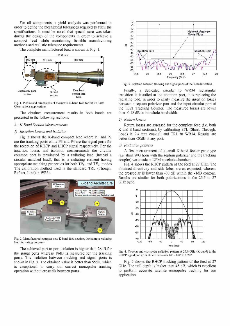
The achieved port to port isolation is higher than 28dB for the signal ports whereas 18dB is measured for the tracking ports. The isolation between tracking and signal ports is shown in Fig. 3. The obtained value is better than 55dB, which is exceptional to carry out correct monopulse tracking operation without crosstalk between ports.
o -5
-10 -15 -20 -25 -30 -35 -40 -45 -50 -55 -60 -65 -70
Isolation
j\ / u W
S31
•A A / M m
Miitu Nois
/
\ A
*WW%A
>ork Analyzer e Floor
Isolation S32 A "N. J ^
K! f
24.5 25 25.5 26 26.5 Frequency (GHz)
27 27.5 28
Fig. 3. Isolation between tracking and signal ports of the K-band section
Finally, a dedicated circular to WR34 rectangular transition is installed at the common port, thus replacing the radiating load, in order to easily measure the insertion losses between a septum polarizer port and the input circular port of the TE21 Tracking Coupler. The measured losses are lower than -0.18 dB in the whole bandwidth.
2) Return Losses
Return losses are assessed for the complete feed (i.e. both K and S band sections), by calibrating STL (Short, Through, Load) in 2.4 mm coaxial, and TRL in WR34. Results are better than -20dB at any port.
3) Radiation patterns
A first measurement of a small K-band feeder prototype (i.e. short WG horn with the septum polarizer and the tracking coupler) was made at UPM anechoic chambers.
Fig. 4 shows the RHCP pattern of the feed at 27 GHz. The obtained directivity and side lobes are as expected, whereas the crosspolar is lower than -30 dB within the -ldB contour. Results are similar for both polarizations in the 25.5 to 27 GHz band.
-10
-15
-o -20
-25
-30
-35
-40 -120
/ /
V?
/ /
l \
ñ V \ • \
k fi
'1 1 1
\
\
A
f 1 i1
f;
\ \
0 40
Theta (deg)
Fig. 4. Copolar and crosspolar radiation pattern at 27.0 GHz (K-band) in the RHCP signal port (P3). 0=cte cuts each 10°. -120°<e<120°
Fig. 5 shows the RHCP tracking pattern of the feed at 27 GHz. The null depth is higher than 45 dB, which is excellent to perform accurate satellite monopulse tracking for our application.

-ISO -120 -60 O 60 120 180 Theta(deg)
Fig. 5. Copolar and crospolar radiation pattern at 27.0 GHz (K-band) in the RHCP Tracking port (PI). <f=0°, 0=45° and <f=90° cuts. -120o<0<120°
4) Axial Ratio
Due to the length of the feed, a dedicated roll positioner had to be built to measure K-band axial ratio and S-band patterns. The measurements were performed at the UPM anechoic chamber.
At the output of the dual band horn, a dielectric radome feed window needs to be installed so as to protect the internal waveguides from rain, snow and dust. An important aspect to be carefully considered is the selection of the appropriate dielectric material, especially at K-band, because the axial ratio is strongly dependent on it. Fig. 6 presents K-band axial ratio using different dielectric materials, being the best the one layer of Mylar that indicates that this material provides the lower reflection. The achieved axial ratio is better than 0.7 dB in the whole band.
1,0
0,9
_ 0 , 8
£ 0 , 7
.2 0,6
K 0,5
¡ 0 , 4 < 0 , 3
0,2
0,1
0,0 25,5 25,6 25,7 25,8 25,9 26,0 26,1 26,2 26,3 26,3 26,4 26,5 26,6 26,7 26,8 26,9 27,0
Frequency (GHz)
Fig. 6. Comparison of axial ratio measurements of the K-band section for different materials for the radome feed window
B. S-Band Section Measurements
1) Return Losses and Isolation
For the S-band section, the measured return loss at both ports is better than -19 dB, whereas the isolation between Tx and Rx ports is lower than -20 dB.
2) Radiation Patterns
Fig. 7 shows the RHCP signal pattern of the feed at 2.3 GHz. In this case, the crosspolar is lower than -25 dB within the -ldB contour. Results are similar for both ports in the 2.025 to 2.3 GHz band.
Mylar
RaydelGR
Raydel SX12
My lar (2 layers)
. A
l\ \
Mil/ III/ 11 W//al iJ Vi H \ -I \ / V *
[T " w v W
0
-5
-10
-15
GQ
•o .20
-25
-30
-35
-40
J? • 1 ^
/ /
%
1
1
J f
,,
y
¿ ;
N
-••i
,-.
v'
\ \
»-0.00:CPC « -45,00; CPC
(-135.00: CPC *=0.00:XPC ( = «.00:XPC *=80.00:XPC « = 135.00: XPC
\
\ \
j *<
\ \
P [/
\
\ J-
\ %
-120 -80 -40 40 80 120
Theta(deg)
Fig. 7. Copolar and crosspolar radiation pattern at 2.30 GHz (S-band) in RHCP port. <f=0°, 0=45°, <f=90° and 0=135° cuts
3) Axial Ratio
Axial ratio is better than 1 dB from 2.025 to 2.3 GHz. In this band, the effect of the dielectric material for the radome feed window is negligible.
V. CONCLUSION
A novel compact simultaneous K/S-band feed for the next generation of Earth Observation ground stations has been presented in this paper. The feed supports the reception of wideband signals in the 25.5 to 27 GHz band in RHCP and LHCP polarizations, and provides TE21 monopulse tracking signals to allow autotrack operation in the ground station. Additionally, the S-band enables the transmission and reception of the TM and TC to the satellite. This new feed has already been successfully integrated into a 6m diameter ADE antenna.
ACKNOWLEDGMENT
The authors wish to thank all their colleagues in Indra Sistemas, Universidad de Cantabria and Universidad Politécnica de Madrid who have collaborated in the work presented here. We would also like to thank the European Space Agency (ESA) for its financial support, and specially Piermario Besso and Guillaume Dauron, from ESA (ESOC) in Germany, for their useful collaboration with their technical reviews.
REFERENCES
[1] C. Chambón, XL. Cano, L de la Fuente, E. Artal, B. Fauroux, and S. Rawson, "Ka-Band Ground Station Low Noise Amplifier Development for Earth Observation Missions," 6th ESA International Workshop on TT&C for Space Applications., Sep. 2013.
[2] L. Sakr, "The Higher Order Modes in the Feeds of the Satellite Monopulse Tracking Antennas," IEEEMELECON., May. 2002
[3] Y. H. Choung, K.R Goudey and L.G Bryans, "Theory and Design of a Ku-Band TE2i-Mode Coupler," IEEE Transactions on Microwave Theory and Techniques, vol. 30, No. 11, pp. 1862-1866, Nov. 1982.
[4] Y. H. Choung, "Wideband TM0i-mode Travelling Wave Coupler," 1EE Proc. Microwave Antenna Propagation, vol. 144, No. 5, pp. 315-320, Oct. 1997.
[5] Roger D. Norrod, et atl. "Design and Implementation of a Low-Noise. Prime-Focus S/X Receiver System for Radioastronomy". Proceedings of the IEEE, Vol 82, N°5. May 1994, pp 768 to 775.
[6] R Behe, P. Brachat, "Compact Duplexer-Polarizer with Semicircular Waveguide". IEEE Transactions on Antennas and Propagation, vol. 39, No. 8, pp. 1222-1224, Aug. 1991.