proposed expansion of speciality chemicals, … · 1 form-i for proposed expansion of speciality...
TRANSCRIPT
1
FORM-I
For
PROPOSED EXPANSION OF SPECIALITY CHEMICALS,
INTERMEDIATES & PESTICIDE TECHANICALS IN EXISTING
UNIT
of
M/s. HEMANI INDUSTRIES LTD. (UNIT-III & IV)
PLOT NO. CH-5 & E-362, G.I.D.C. ESTATE, DAHEJ-I,
TAL: VAGRA, DIST: BHARUCH-392130, GUJARAT
2
APPENDIX I
FORM 1
1. Basic Information
Sr.
No.
Item Details
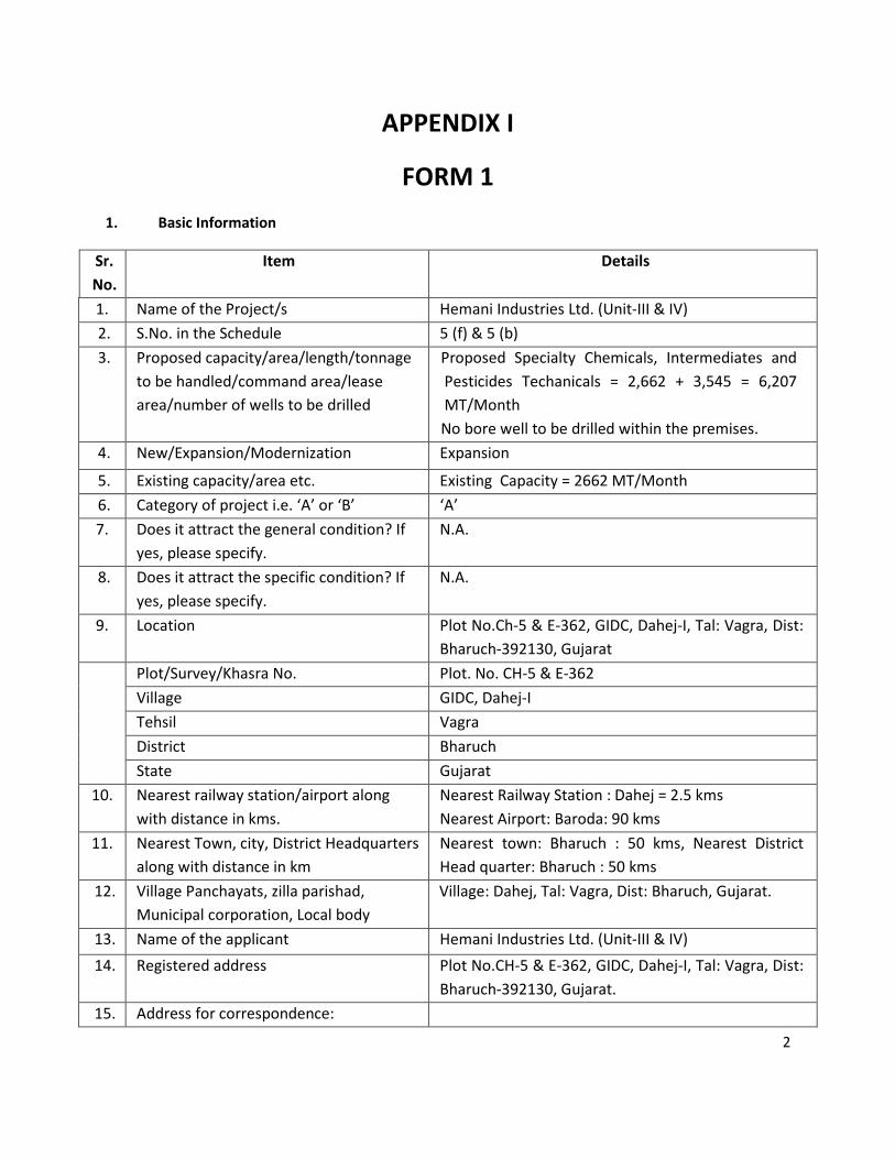
1. Name of the Project/s Hemani Industries Ltd. (Unit-III & IV)
2. S.No. in the Schedule 5 (f) & 5 (b)
3. Proposed capacity/area/length/tonnage
to be handled/command area/lease
area/number of wells to be drilled
Proposed Specialty Chemicals, Intermediates and
Pesticides Techanicals = 2,662 + 3,545 = 6,207
MT/Month
No bore well to be drilled within the premises.
4. New/Expansion/Modernization Expansion
5. Existing capacity/area etc. Existing Capacity = 2662 MT/Month
6. Category of project i.e. ‘A’ or ‘B’ ‘A’
7. Does it attract the general condition? If
yes, please specify.
N.A.
8. Does it attract the specific condition? If
yes, please specify.
N.A.
9. Location Plot No.Ch-5 & E-362, GIDC, Dahej-I, Tal: Vagra, Dist:
Bharuch-392130, Gujarat
Plot/Survey/Khasra No. Plot. No. CH-5 & E-362
Village GIDC, Dahej-I
Tehsil Vagra
District Bharuch
State Gujarat
10. Nearest railway station/airport along
with distance in kms.
Nearest Railway Station : Dahej = 2.5 kms
Nearest Airport: Baroda: 90 kms
11. Nearest Town, city, District Headquarters
along with distance in km
Nearest town: Bharuch : 50 kms, Nearest District
Head quarter: Bharuch : 50 kms
12. Village Panchayats, zilla parishad,
Municipal corporation, Local body
Village: Dahej, Tal: Vagra, Dist: Bharuch, Gujarat.
13. Name of the applicant Hemani Industries Ltd. (Unit-III & IV)
14. Registered address Plot No.CH-5 & E-362, GIDC, Dahej-I, Tal: Vagra, Dist:
Bharuch-392130, Gujarat.
15. Address for correspondence:
3
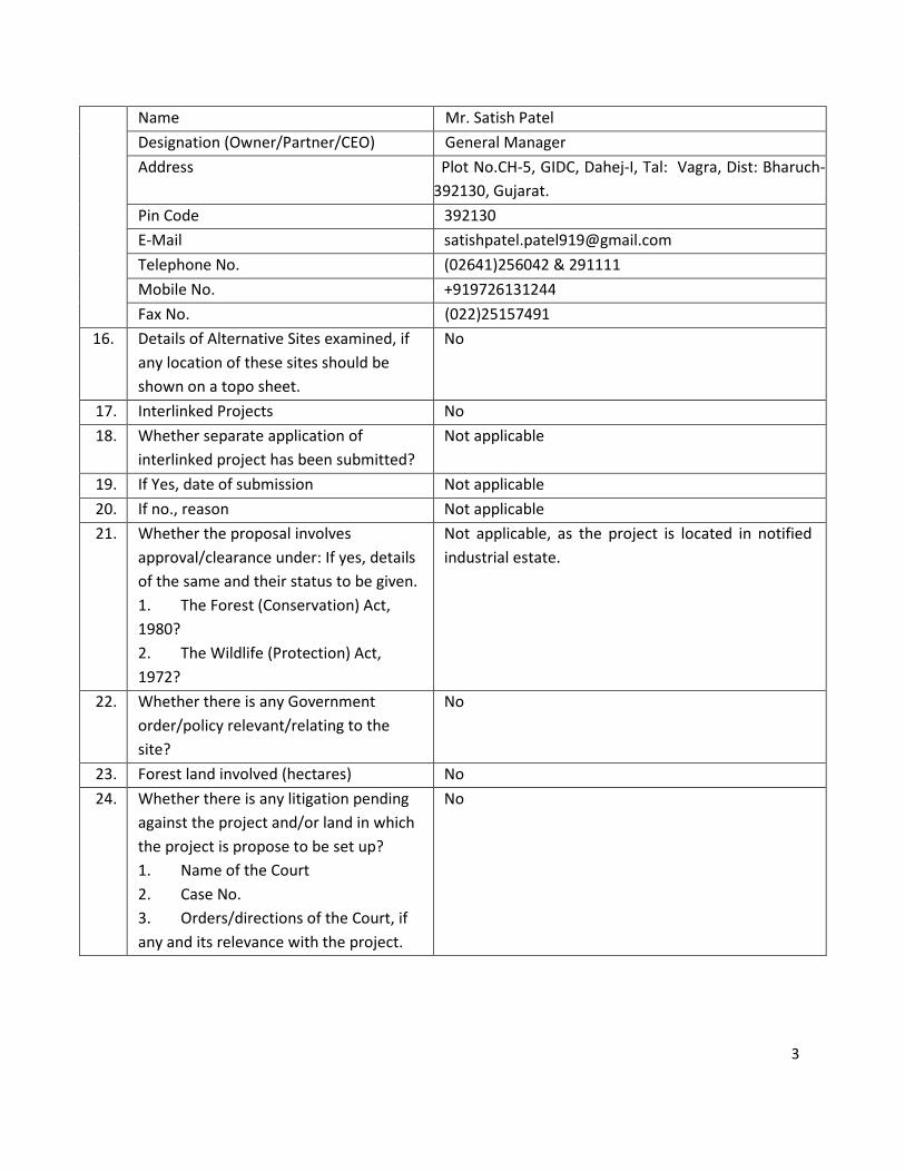
Name Mr. Satish Patel
Designation (Owner/Partner/CEO) General Manager
Address Plot No.CH-5, GIDC, Dahej-I, Tal: Vagra, Dist: Bharuch-
392130, Gujarat.
Pin Code 392130
E-Mail [email protected]
Telephone No. (02641)256042 & 291111
Mobile No. +919726131244
Fax No. (022)25157491
16. Details of Alternative Sites examined, if
any location of these sites should be
shown on a topo sheet.
No
17. Interlinked Projects No
18. Whether separate application of
interlinked project has been submitted?
Not applicable
19. If Yes, date of submission Not applicable
20. If no., reason Not applicable
21.
Whether the proposal involves
approval/clearance under: If yes, details
of the same and their status to be given.
1. The Forest (Conservation) Act,
1980?
2. The Wildlife (Protection) Act,
1972?
Not applicable, as the project is located in notified
industrial estate.
22. Whether there is any Government
order/policy relevant/relating to the
site?
No
23. Forest land involved (hectares) No
24. Whether there is any litigation pending
against the project and/or land in which
the project is propose to be set up?
1. Name of the Court
2. Case No.
3. Orders/directions of the Court, if
any and its relevance with the project.
No
4
(II) Activity
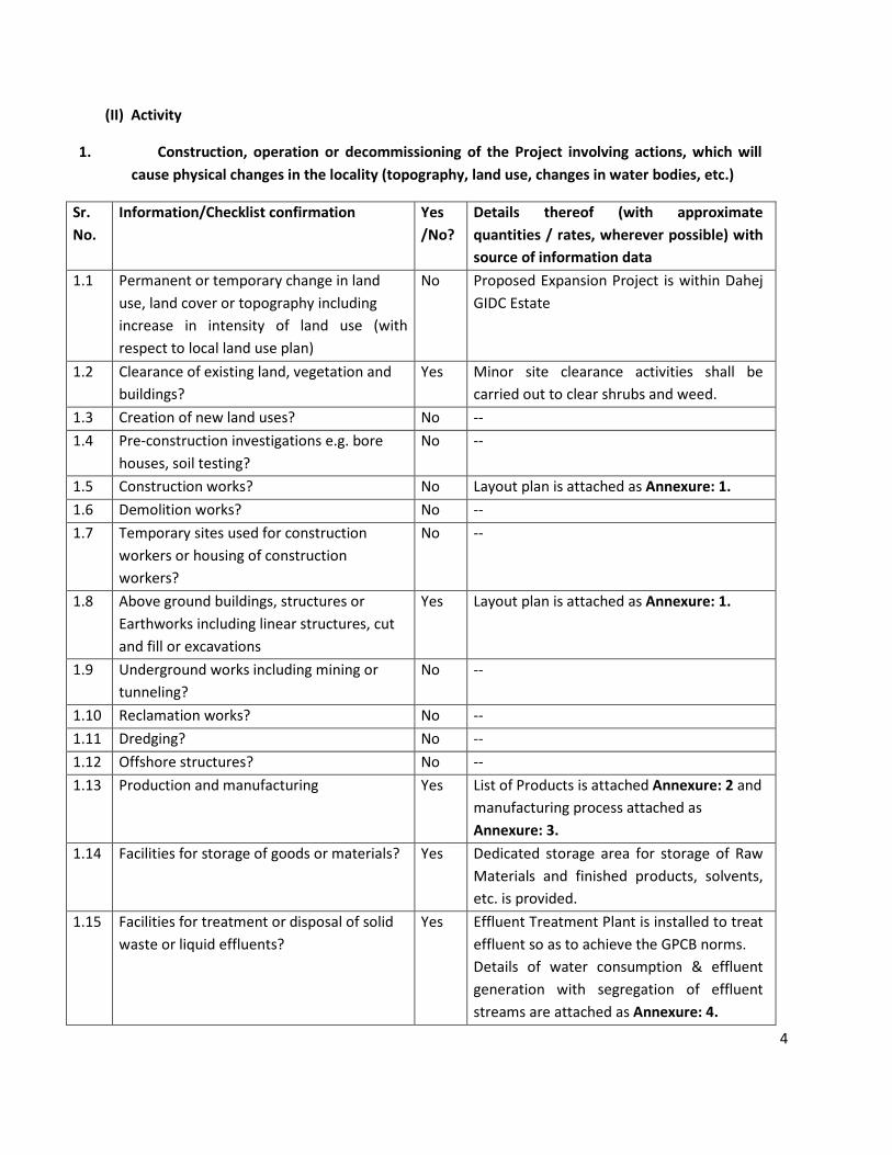
1. Construction, operation or decommissioning of the Project involving actions, which will
cause physical changes in the locality (topography, land use, changes in water bodies, etc.)
Sr.
No.
Information/Checklist confirmation Yes
/No?
Details thereof (with approximate
quantities / rates, wherever possible) with
source of information data
1.1 Permanent or temporary change in land
use, land cover or topography including
increase in intensity of land use (with
respect to local land use plan)
No Proposed Expansion Project is within Dahej
GIDC Estate
1.2 Clearance of existing land, vegetation and
buildings?
Yes Minor site clearance activities shall be
carried out to clear shrubs and weed.
1.3 Creation of new land uses? No --
1.4 Pre-construction investigations e.g. bore
houses, soil testing?
No --
1.5 Construction works? No Layout plan is attached as Annexure: 1.
1.6 Demolition works? No --
1.7
Temporary sites used for construction
workers or housing of construction
workers?
No --
1.8 Above ground buildings, structures or
Earthworks including linear structures, cut
and fill or excavations
Yes Layout plan is attached as Annexure: 1.
1.9
Underground works including mining or
tunneling?
No --
1.10 Reclamation works? No --
1.11 Dredging? No --
1.12 Offshore structures? No --
1.13 Production and manufacturing Yes List of Products is attached Annexure: 2 and
manufacturing process attached as
Annexure: 3.
1.14 Facilities for storage of goods or materials? Yes Dedicated storage area for storage of Raw
Materials and finished products, solvents,
etc. is provided.
1.15
Facilities for treatment or disposal of solid
waste or liquid effluents?
Yes Effluent Treatment Plant is installed to treat
effluent so as to achieve the GPCB norms.
Details of water consumption & effluent
generation with segregation of effluent
streams are attached as Annexure: 4.
5
Details of proposed Effluent Treatment
Plant are attached as Annexure: 5.
Details of Hazardous waste generation and
disposal is attached as Annexure: 6.
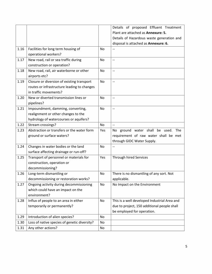
1.16
Facilities for long term housing of
operational workers?
No --
1.17 New road, rail or sea traffic during
construction or operation?
No --
1.18 New road, rail, air waterborne or other
airports etc?
No --
1.19 Closure or diversion of existing transport
routes or infrastructure leading to changes
in traffic movements?
No --
1.20 New or diverted transmission lines or
pipelines?
No --
1.21
Impoundment, damming, converting,
realignment or other changes to the
hydrology of watercourses or aquifers?
No --
1.22 Stream crossings? No --
1.23
Abstraction or transfers or the water form
ground or surface waters?
Yes No ground water shall be used. The
requirement of raw water shall be met
through GIDC Water Supply.
1.24
Changes in water bodies or the land
surface affecting drainage or run-off?
No --
1.25
Transport of personnel or materials for
construction, operation or
decommissioning?
Yes Through hired Services
1.26 Long-term dismantling or
decommissioning or restoration works?
No There is no dismantling of any sort. Not
applicable.
1.27 Ongoing activity during decommissioning
which could have an impact on the
environment?
No No Impact on the Environment
1.28
Influx of people to an area in either
temporarily or permanently?
No This is a well developed Industrial Area and
due to project, 150 additional people shall
be employed for operation.
1.29 Introduction of alien species? No
1.30 Loss of native species of genetic diversity? No
1.31 Any other actions? No
6
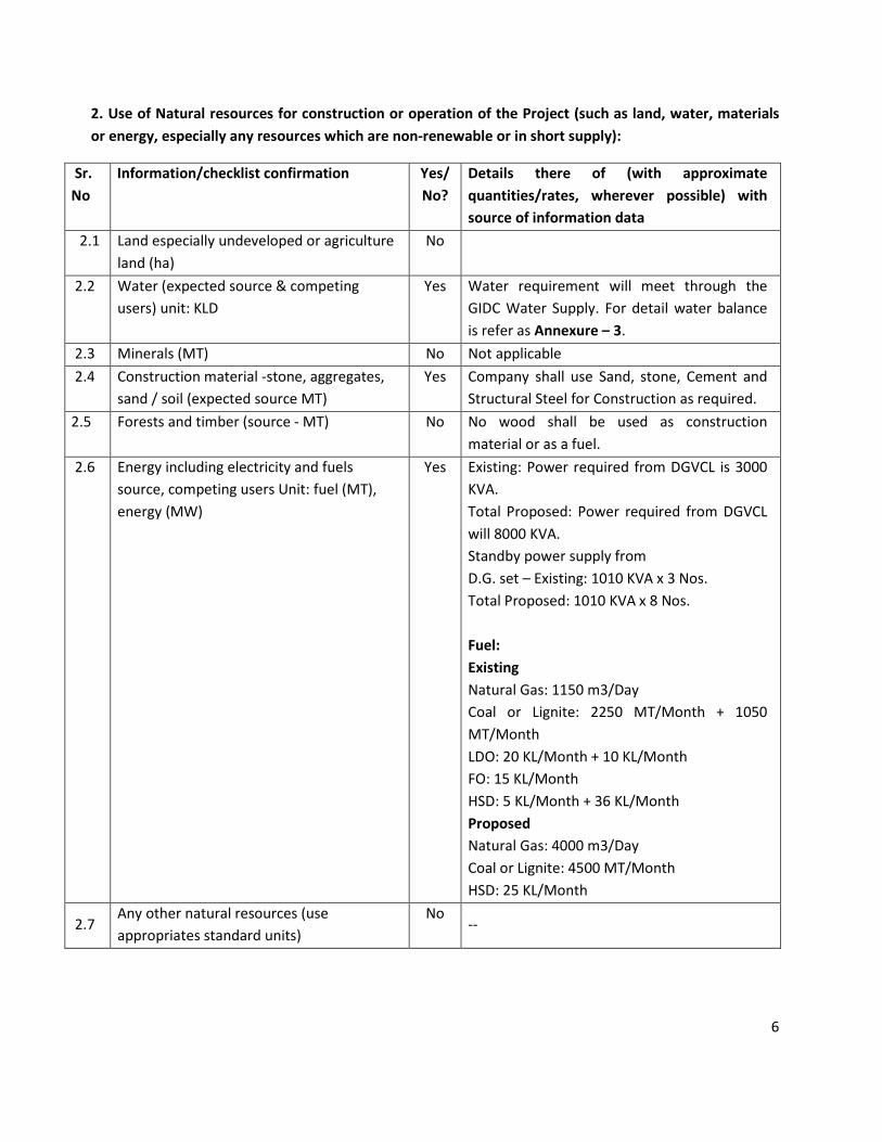
2. Use of Natural resources for construction or operation of the Project (such as land, water, materials
or energy, especially any resources which are non-renewable or in short supply):
Sr.
No
Information/checklist confirmation Yes/
No?
Details there of (with approximate
quantities/rates, wherever possible) with
source of information data
2.1 Land especially undeveloped or agriculture
land (ha)
No
2.2 Water (expected source & competing
users) unit: KLD
Yes Water requirement will meet through the
GIDC Water Supply. For detail water balance
is refer as Annexure – 3.
2.3 Minerals (MT) No Not applicable
2.4
Construction material -stone, aggregates,
sand / soil (expected source MT)
Yes Company shall use Sand, stone, Cement and
Structural Steel for Construction as required.
2.5 Forests and timber (source - MT) No No wood shall be used as construction
material or as a fuel.
2.6
Energy including electricity and fuels
source, competing users Unit: fuel (MT),
energy (MW)
Yes Existing: Power required from DGVCL is 3000
KVA.
Total Proposed: Power required from DGVCL
will 8000 KVA.
Standby power supply from
D.G. set – Existing: 1010 KVA x 3 Nos.
Total Proposed: 1010 KVA x 8 Nos.
Fuel:
Existing
Natural Gas: 1150 m3/Day
Coal or Lignite: 2250 MT/Month + 1050
MT/Month
LDO: 20 KL/Month + 10 KL/Month
FO: 15 KL/Month
HSD: 5 KL/Month + 36 KL/Month
Proposed
Natural Gas: 4000 m3/Day
Coal or Lignite: 4500 MT/Month
HSD: 25 KL/Month
2.7 Any other natural resources (use
appropriates standard units)
No --
7
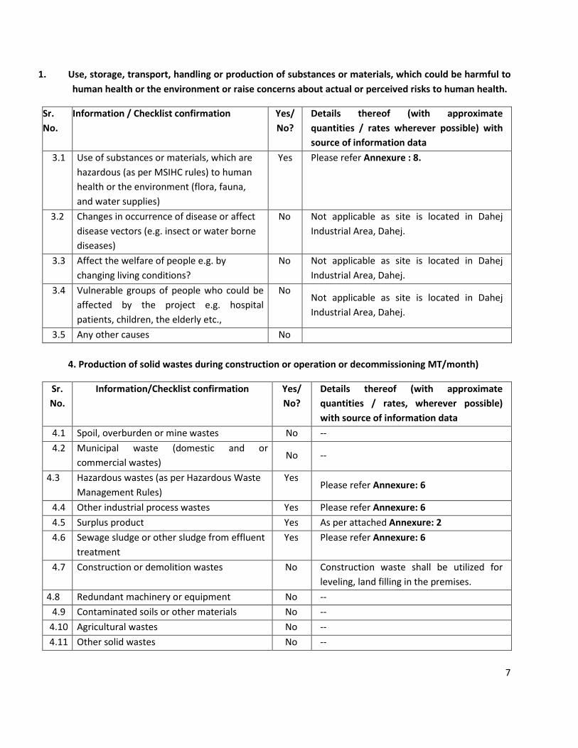
1. Use, storage, transport, handling or production of substances or materials, which could be harmful to
human health or the environment or raise concerns about actual or perceived risks to human health.
Sr.
No.
Information / Checklist confirmation Yes/
No?
Details thereof (with approximate
quantities / rates wherever possible) with
source of information data
3.1 Use of substances or materials, which are
hazardous (as per MSIHC rules) to human
health or the environment (flora, fauna,
and water supplies)
Yes
Please refer Annexure : 8.
3.2 Changes in occurrence of disease or affect
disease vectors (e.g. insect or water borne
diseases)
No Not applicable as site is located in Dahej
Industrial Area, Dahej.
3.3 Affect the welfare of people e.g. by
changing living conditions?
No Not applicable as site is located in Dahej
Industrial Area, Dahej.
3.4
Vulnerable groups of people who could be
affected by the project e.g. hospital
patients, children, the elderly etc.,
No Not applicable as site is located in Dahej
Industrial Area, Dahej.
3.5 Any other causes No
4. Production of solid wastes during construction or operation or decommissioning MT/month)
Sr.
No.
Information/Checklist confirmation Yes/
No?
Details thereof (with approximate
quantities / rates, wherever possible)
with source of information data
4.1 Spoil, overburden or mine wastes No --
4.2
Municipal waste (domestic and or
commercial wastes) No --
4.3
Hazardous wastes (as per Hazardous Waste
Management Rules)
Yes Please refer Annexure: 6
4.4 Other industrial process wastes Yes Please refer Annexure: 6
4.5 Surplus product Yes As per attached Annexure: 2
4.6
Sewage sludge or other sludge from effluent
treatment
Yes Please refer Annexure: 6
4.7 Construction or demolition wastes No Construction waste shall be utilized for
leveling, land filling in the premises.
4.8 Redundant machinery or equipment No --
4.9 Contaminated soils or other materials No --
4.10 Agricultural wastes No --
4.11 Other solid wastes No --
8
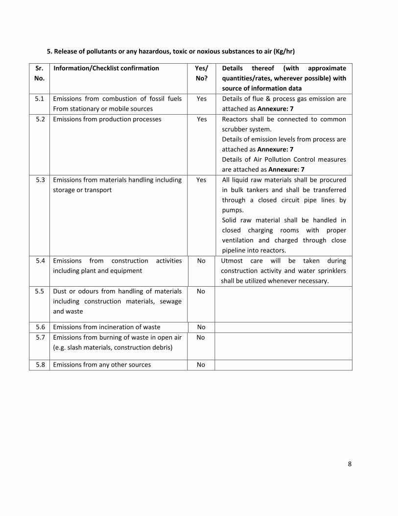
5. Release of pollutants or any hazardous, toxic or noxious substances to air (Kg/hr)
Sr.
No.
Information/Checklist confirmation Yes/
No?
Details thereof (with approximate
quantities/rates, wherever possible) with
source of information data
5.1 Emissions from combustion of fossil fuels
From stationary or mobile sources
Yes Details of flue & process gas emission are
attached as Annexure: 7
5.2 Emissions from production processes Yes Reactors shall be connected to common
scrubber system.
Details of emission levels from process are
attached as Annexure: 7
Details of Air Pollution Control measures
are attached as Annexure: 7
5.3 Emissions from materials handling including
storage or transport
Yes All liquid raw materials shall be procured
in bulk tankers and shall be transferred
through a closed circuit pipe lines by
pumps.
Solid raw material shall be handled in
closed charging rooms with proper
ventilation and charged through close
pipeline into reactors.
5.4 Emissions from construction activities
including plant and equipment
No Utmost care will be taken during
construction activity and water sprinklers
shall be utilized whenever necessary.
5.5
Dust or odours from handling of materials
including construction materials, sewage
and waste
No
5.6 Emissions from incineration of waste No
5.7 Emissions from burning of waste in open air
(e.g. slash materials, construction debris)
No
5.8 Emissions from any other sources No
9
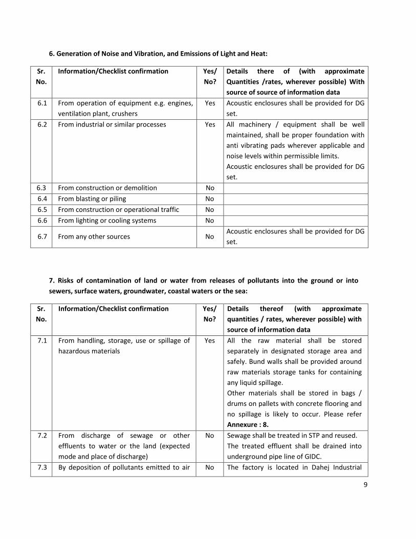
6. Generation of Noise and Vibration, and Emissions of Light and Heat:
Sr.
No.
Information/Checklist confirmation Yes/
No?
Details there of (with approximate
Quantities /rates, wherever possible) With
source of source of information data
6.1
From operation of equipment e.g. engines,
ventilation plant, crushers
Yes Acoustic enclosures shall be provided for DG
set.
6.2 From industrial or similar processes Yes All machinery / equipment shall be well
maintained, shall be proper foundation with
anti vibrating pads wherever applicable and
noise levels within permissible limits.
Acoustic enclosures shall be provided for DG
set.
6.3 From construction or demolition No
6.4 From blasting or piling No
6.5 From construction or operational traffic No
6.6 From lighting or cooling systems No
6.7 From any other sources No Acoustic enclosures shall be provided for DG
set.
7. Risks of contamination of land or water from releases of pollutants into the ground or into
sewers, surface waters, groundwater, coastal waters or the sea:
Sr.
No.
Information/Checklist confirmation Yes/
No?
Details thereof (with approximate
quantities / rates, wherever possible) with
source of information data
7.1
From handling, storage, use or spillage of
hazardous materials
Yes All the raw material shall be stored
separately in designated storage area and
safely. Bund walls shall be provided around
raw materials storage tanks for containing
any liquid spillage.
Other materials shall be stored in bags /
drums on pallets with concrete flooring and
no spillage is likely to occur. Please refer
Annexure : 8.
7.2
From discharge of sewage or other
effluents to water or the land (expected
mode and place of discharge)
No Sewage shall be treated in STP and reused.
The treated effluent shall be drained into
underground pipe line of GIDC.
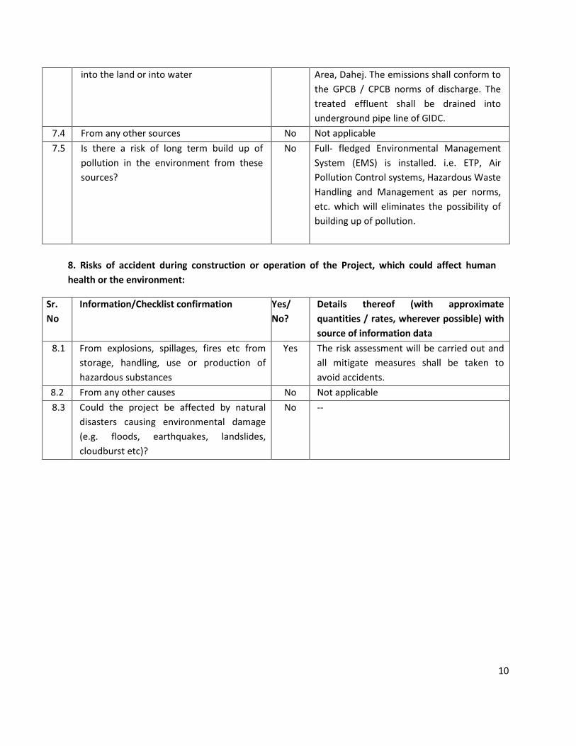
7.3 By deposition of pollutants emitted to air No The factory is located in Dahej Industrial
10
into the land or into water Area, Dahej. The emissions shall conform to
the GPCB / CPCB norms of discharge. The
treated effluent shall be drained into
underground pipe line of GIDC.
7.4 From any other sources No Not applicable
7.5 Is there a risk of long term build up of
pollution in the environment from these
sources?
No
Full- fledged Environmental Management
System (EMS) is installed. i.e. ETP, Air
Pollution Control systems, Hazardous Waste
Handling and Management as per norms,
etc. which will eliminates the possibility of
building up of pollution.
8. Risks of accident during construction or operation of the Project, which could affect human
health or the environment:
Sr.
No
Information/Checklist confirmation
Yes/
No?
Details thereof (with approximate
quantities / rates, wherever possible) with
source of information data
8.1 From explosions, spillages, fires etc from
storage, handling, use or production of
hazardous substances
Yes The risk assessment will be carried out and
all mitigate measures shall be taken to
avoid accidents.
8.2 From any other causes No Not applicable
8.3 Could the project be affected by natural
disasters causing environmental damage
(e.g. floods, earthquakes, landslides,
cloudburst etc)?
No --
11
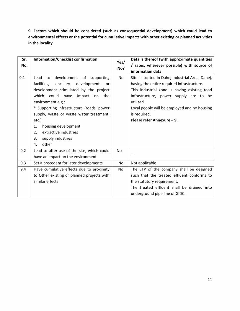
9. Factors which should be considered (such as consequential development) which could lead to
environmental effects or the potential for cumulative impacts with other existing or planned activities
in the locality
Sr.
No.
Information/Checklist confirmation Yes/
No?
Details thereof (with approximate quantities
/ rates, wherever possible) with source of
information data
9.1 Lead to development of supporting
facilities, ancillary development or
development stimulated by the project
which could have impact on the
environment e.g.:
* Supporting infrastructure (roads, power
supply, waste or waste water treatment,
etc.)
1. housing development
2. extractive industries
3. supply industries
4. other
No Site is located in Dahej Industrial Area, Dahej,
having the entire required infrastructure.
This industrial zone is having existing road
infrastructure, power supply are to be
utilized.
Local people will be employed and no housing
is required.
Please refer Annexure – 9.
9.2
Lead to after-use of the site, which could
have an impact on the environment
No --
9.3 Set a precedent for later developments No Not applicable
9.4 Have cumulative effects due to proximity
to Other existing or planned projects with
similar effects
No The ETP of the company shall be designed
such that the treated effluent conforms to
the statutory requirement.
The treated effluent shall be drained into
underground pipe line of GIDC.
12
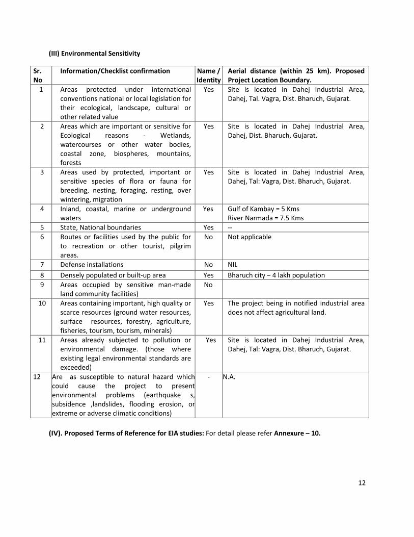
(III) Environmental Sensitivity
Sr.
No
Information/Checklist confirmation Name /
Identity
Aerial distance (within 25 km). Proposed
Project Location Boundary.
1 Areas protected under international
conventions national or local legislation for
their ecological, landscape, cultural or
other related value
Yes Site is located in Dahej Industrial Area,
Dahej, Tal. Vagra, Dist. Bharuch, Gujarat.
2 Areas which are important or sensitive for
Ecological reasons - Wetlands,
watercourses or other water bodies,
coastal zone, biospheres, mountains,
forests
Yes Site is located in Dahej Industrial Area,
Dahej, Dist. Bharuch, Gujarat.
3 Areas used by protected, important or
sensitive species of flora or fauna for
breeding, nesting, foraging, resting, over
wintering, migration
Yes Site is located in Dahej Industrial Area,
Dahej, Tal: Vagra, Dist. Bharuch, Gujarat.
4 Inland, coastal, marine or underground
waters
Yes Gulf of Kambay = 5 Kms
River Narmada = 7.5 Kms
5 State, National boundaries Yes --
6 Routes or facilities used by the public for
to recreation or other tourist, pilgrim
areas.
No Not applicable
7 Defense installations No NIL
8 Densely populated or built-up area Yes Bharuch city – 4 lakh population
9 Areas occupied by sensitive man-made
land community facilities)
No
10 Areas containing important, high quality or
scarce resources (ground water resources,
surface resources, forestry, agriculture,
fisheries, tourism, tourism, minerals)
Yes
The project being in notified industrial area
does not affect agricultural land.
11 Areas already subjected to pollution or
environmental damage. (those where
existing legal environmental standards are
exceeded)
Yes Site is located in Dahej Industrial Area,
Dahej, Tal: Vagra, Dist. Bharuch, Gujarat.
12 Are as susceptible to natural hazard which
could cause the project to present
environmental problems (earthquake s,
subsidence ,landslides, flooding erosion, or
extreme or adverse climatic conditions)
- N.A.
(IV). Proposed Terms of Reference for EIA studies: For detail please refer Annexure – 10.
13
I hereby given undertaking that, the data and information given in the application and enclosures are
true to the best of my knowledge and belief and I am aware that if any part of the data and information
submitted is found to be false or misleading at any stage the project will be rejected and clearance
given, if any to the project will be revoked at our risk and cost.
Date: 10.04.2017 For Hemani Intermediates Pvt. Ltd.
Place:Dahej
Satish Patel
(General Manager)
NOTE:
1. The projects involving clearance under Coastal Regulation Zone Notification, 1991 shall be
submitted with the application a C.R.Z. map duly demarcated by one of the authorized
agencies, showing the project activities, w.r.t. C.R.Z. (at the stage of TOR) and the
recommendations of the State Coastal Zone Management Authority (at the stage of EC).
Simultaneous action shall also be taken to obtain the requisite clearance under the provisions
of the C.R.Z. Notification, 1991 for the activities to be located in the CRZ.
2. The projects to be located within 60 km of the National Parks, Sanctuaries, Biosphere
Reserves, Migratory Corridors of Wild Animals, the project proponent shall submit the map
duly authenticated by Chief Wildlife Warden showing these features vis-à-vis the project
location and the recommendations or comments of the Chief Wildlife Warden thereon (at
the stage of EC).
3. All correspondence with the Ministry of Environment & Forests including submission of application for
TOR/Environmental Clearance, subsequent clarifications, as may be required from time to time,
participation in the EAC Meeting on behalf of the project proponent shall be made by the authorized
signatory only. The authorized signatory should also submit a document in support of his claim of
being an authorized signatory for the specific project.
14
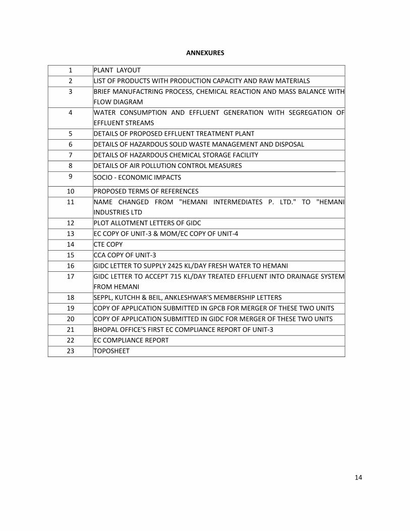
ANNEXURES
1 PLANT LAYOUT
2 LIST OF PRODUCTS WITH PRODUCTION CAPACITY AND RAW MATERIALS
3 BRIEF MANUFACTRING PROCESS, CHEMICAL REACTION AND MASS BALANCE WITH
FLOW DIAGRAM
4 WATER CONSUMPTION AND EFFLUENT GENERATION WITH SEGREGATION OF
EFFLUENT STREAMS
5 DETAILS OF PROPOSED EFFLUENT TREATMENT PLANT
6 DETAILS OF HAZARDOUS SOLID WASTE MANAGEMENT AND DISPOSAL
7 DETAILS OF HAZARDOUS CHEMICAL STORAGE FACILITY
8 DETAILS OF AIR POLLUTION CONTROL MEASURES
9 SOCIO - ECONOMIC IMPACTS
10 PROPOSED TERMS OF REFERENCES
11 NAME CHANGED FROM "HEMANI INTERMEDIATES P. LTD." TO "HEMANI
INDUSTRIES LTD
12 PLOT ALLOTMENT LETTERS OF GIDC
13 EC COPY OF UNIT-3 & MOM/EC COPY OF UNIT-4
14 CTE COPY
15 CCA COPY OF UNIT-3
16 GIDC LETTER TO SUPPLY 2425 KL/DAY FRESH WATER TO HEMANI
17 GIDC LETTER TO ACCEPT 715 KL/DAY TREATED EFFLUENT INTO DRAINAGE SYSTEM
FROM HEMANI
18 SEPPL, KUTCHH & BEIL, ANKLESHWAR'S MEMBERSHIP LETTERS
19 COPY OF APPLICATION SUBMITTED IN GPCB FOR MERGER OF THESE TWO UNITS
20 COPY OF APPLICATION SUBMITTED IN GIDC FOR MERGER OF THESE TWO UNITS
21 BHOPAL OFFICE'S FIRST EC COMPLIANCE REPORT OF UNIT-3
22 EC COMPLIANCE REPORT
23 TOPOSHEET
15
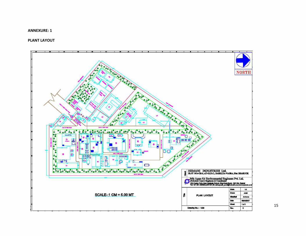
ANNEXURE: 1
PLANT LAYOUT
16
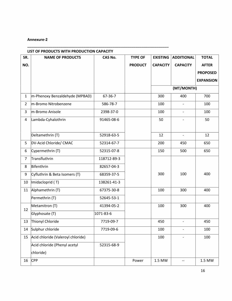
Annexure-2
____________________________________________________________________
LIST OF PRODUCTS WITH PRODUCTION CAPACITY
SR.
NO.
NAME OF PRODUCTS CAS No. TYPE OF
PRODUCT
EXISTING
CAPACITY
ADDITIONAL
CAPACITY
TOTAL
AFTER
PROPOSED
EXPANSION
(MT/MONTH)
1 m-Phenoxy Benzaldehyde (MPBAD) 67-36-7 300 400 700
2 m-Bromo Nitrobenzene 586-78-7 100 - 100
3 m-Bromo Anisole 2398-37-0 100 - 100
4 Lambda-Cyhalothrin 91465-08-6 50
-
50
Deltamethrin (T) 52918-63-5 12 - 12
5 DV-Acid Chloride/ CMAC 52314-67-7 200 450 650
6 Cypermethrin (T) 52315-07-8 150 500 650
7 Transfluthrin 118712-89-3
300
100
400
8 Bifenthrin 82657-04-3
9 Cyfluthrin & Beta Isomers (T) 68359-37-5
10 Imidacloprid ( T) 138261-41-3
11 Alphamethrin (T) 67375-30-8 100 300 400
Permethrin (T) 52645-53-1
12 Metamitron (T) 41394-05-2 100 300 400
Glyphosate (T) 1071-83-6
13 Thionyl Chloride 7719-09-7 450 - 450
14 Sulphur chloride 7719-09-6 100 - 100
15 Acid chloride (Valeroyl chloride) 100 - 100
Acid chloride (Phenyl acetyl
chloride)
52315-68-9
16 CPP Power 1.5 MW -- 1.5 MW

17
generation
17 Zeta Cypermethrin 52315-07-08 Insecticide - 100 100
18 Beta Cypermethrin 86753-92-6 Insecticide - 50 50
19 Chlorantraniliprole 500008-45-7 Insecticide - 50 50
20 Fipronil 120068-37-3 Insecticide - 25 25
21 Acetamaprid 160430-64-8 Insecticides - 100 100
Imidacloroprid 138261-41-3
22 Hexaconzole 79983-71-4 Fungicide 300 250 550
Tebuconzole 107534-96-3
Propinoconozole 60207-90-1
23 Pendimethalin 40487421 Herbicide
300
500
800 24 Metribuzin 21087-64-9 Herbicide
25 Dicamba 1918-00-9 Herbicide
26 2,5 Dichloro Phenol 583-78-8 Intermediates - 200 200
27 2,4 Di chloro phenoxy Acetic Acid 94-75-7 Herbicide - 200 200
28 Pyraclostobin 175013-18-0 Organic
Intermediate
- 50 50
29 1R Hightrans CMA 52314-67-7 Intermediate - 20 20
30 High Trans CMA and CMAC 52314-67-7 Intermediates - 50 50
High Cis CMA and CMAC 52314-67-7
Total 2,662 3,545 6,207
31 HCl (30%) By-product 263.75 1,401.25 1,665
32 Sodium Sulfite By-product 1,000.25 3,829.75 4,830
33 Ammonium Chloride (20% Solution) By-product 425 4,495 4,920
34 Aluminum Chloride (25% Solution) By-product 1,500 -- 1,500
35 KCl (25% Solution) By-product 1,610 940 2,550
36 Spent Sulphuric Acid By-product 700 405 1,105
37 Sodium Sulphate (30% to 35%
Solution)
By-product 2,000 5,240 7,240
38 Potassium Bromide By-product -- 215 215
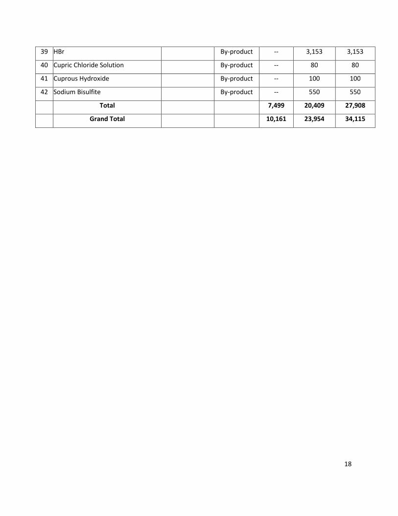
18
39 HBr By-product -- 3,153 3,153
40 Cupric Chloride Solution By-product -- 80 80
41 Cuprous Hydroxide By-product -- 100 100
42 Sodium Bisulfite By-product -- 550 550
Total 7,499 20,409 27,908
Grand Total 10,161 23,954 34,115

19
LIST OF RAW MATERIALS
SR.
NO.
RAW MATERIALS QUANTITY
(MT/MONTH)
1. Meta Phenoxy Benzaldehyde (Organic Intermediate)
C.S. Lye 162.4
BZH 581.0
Bromine 472.5
Chlorine 185.2
EDC 2691
HCl 612
Formic Acid 6.9
Na2SO4 16.0
ASR 7.00
MEG 6.00
PTSA 2.8
Phenol 513.76
KOH 314.5
Toluene 765.4
H2SO4 45.43
2. Meta Bromo Nitrobenzene (Organic Intermediate)
H2SO4 140
Oleum 160
Nitro Benzene 98.4
Bromine 52
Catalyst 0.6
Toluene 344
3. Meta Bromo Anisole (Organic Intermediate)
3 – Bromo Nitrobenzene 125
KOH 98.6
Tetra butyl Ammonium Bromide 31.6
Methanol 26
Toluene 4.6
30 % HCl 42
4.A Lambda Cyhalothrin (Pesticide)
C. S. Lye 25.52
Lambda Cyhalothric Acid 29.12
Thionyl Chloride ( TC ) 15.52
D M Formamide ( DMF ) 0.12
Hexane 271.68
NaCN 8
TEBA ( Catalyst ) 0.56
Soda Ash 0.56
20
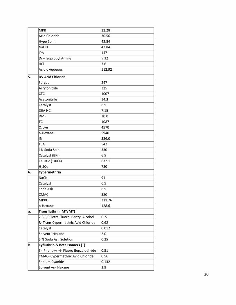
MPB 22.28
Acid Chloride 30.56
Hypo Soln. 42.84
NaOH 42.84
IPA 147
Di – Isopropyl Amine 5.32
HCl 7.6
Acidic Aqueous 112.92
5. DV Acid Chloride
Forcut 247
Acrylonitrile 325
CTC 1007
Acetonitrile 14.3
Catalyst 6.5
DEA HCl 7.15
DMF 20.0
TC 1087
C. Lye 4570
n-Hexane 5940
IB 386.0
TEA 542
1% Soda Soln. 330
Catalyst (BF3) 6.5
Caustic (100%) 632.1
H2SO4 780
6. Cypermethrin
NaCN 91
Catalyst 6.5
Soda Ash 6.5
CMAC 380
MPBD 311.76
n-Hexane 128.6
a. Transfluthrin (MT/MT)
2,3,5,6 Tetra Fluoro Benzyl Alcohol 0. 5
R- Trans Cypermethric Acid Chloride 0.62
Catalyst 0.012
Solvent- Hexane 2.0
5 % Soda Ash Solution 0.25
b. Cyfluthrin & Beta Isomers (T)
3- Phenoxy -4- Fluoro Benzaldehyde 0.51
CMAC- Cypermethric Avid Chloride 0.56
Sodium Cyanide 0.132
Solvent –n- Hexane 2.9
21
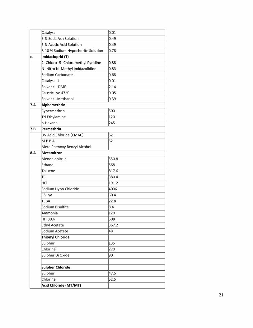
Catalyst 0.01
5 % Soda Ash Solution 0.49
5 % Acetic Acid Solution 0.49
8-10 % Sodium Hypochorite Solution 0.78
c. Imidacloprid (T)
2- Chloro -5- Chloromethyl Pyridine 0.88
N- Nitro N- Methyl Imidazolidine 0.83
Sodium Carbonate 0.68
Catalyst -1 0.01
Solvent - DMF 2.14
Caustic Lye 47 % 0.05
Solvent - Methanol 0.39
7.A Alphamethrin
Cypermethrin 500
Tri Ethylamine 120
n-Hexane 245
7.B Permethrin
DV Acid Chloride (CMAC) 62
M P B A L
Meta Phenoxy Benzyl Alcohol
52
8.A Metamitron
Mendelonitrile 550.8
Ethanol 568
Toluene 817.6
TC 380.4
HCl 191.2
Sodium Hypo Chloride 4006
CS Lye 60.4
TEBA 22.8
Sodium Bisulfite 8.4
Ammonia 120
HH 80% 608
Ethyl Acetate 367.2
Sodium Acetate 48
Thionyl Chloride
Sulphur 135
Chlorine 270
Sulpher Di Oxide 90
Sulpher Chloride
Sulphur 47.5
Chlorine 52.5
Acid Chloride (MT/MT)
22
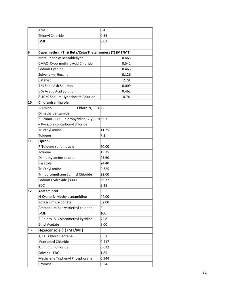
Acid 0.4
Thionyl Chloride 0.55
DMF 0.03
9 Cypermethrin (T) & Beta/Zeta/Theta Isomers (T) (MT/MT)
Meta Phenoxy Benzaldehyde 0.463
CMAC- Cypermethric Acid Chloride 0.542
Sodium Cyanide 0.463
Solvent –n- Hexane 0.126
Catalyst 2.78
4 % Soda Ash Solution 0.009
5 % Acetic Acid Solution 0.463
8-10 % Sodium Hypochorite Solution 0.74
10 Chlorantraniliprole
2-Amino – 5 – Chloro-N, 3-
Dimethylbenzamide
22
3-Bromo -1-(3- Chloropyridine -2-yl)-1H
– Pyrazole -5- carbonyl chloride
35.3
Tri ethyl amine 11.25
Toluene 7.3
11. Fipronil
P-Toluene sulfonic acid 20.00
Toluene 1.675
Di methylamine solution 25.60
Pyrazole 24.40
Tri Ethyl amine 2.325
Trifluoromethane Sulfinyl Chloride 22.00
Sodium Hydroxide (30%) 36.37
EDC 6.25
12. Acetamiprid
N-Cyano-N-Methylacetamidine 44.00
Potassium Carbonate 62.00
Ammonium Benzyltriethyl chloride 2
DMF 100
2-Chloro -5- Chloromethyl Pyridine 72.8
Ethyl Acetate 8.00
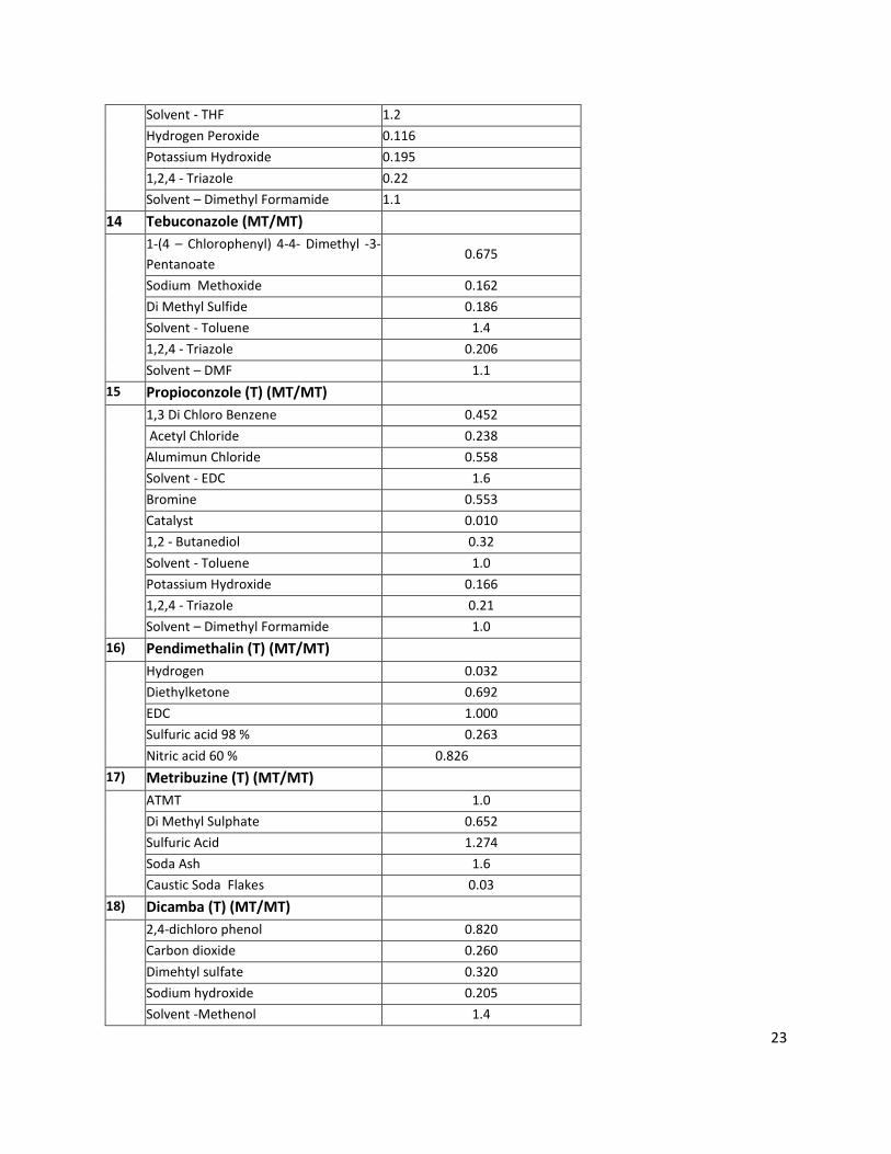
13. Hexaconzole (T) (MT/MT)
1,3 Di Chloro Benzene 0.51
Pentanoyl Chloride 0.417
Alumimun Chloride 0.632
Solvent - EDC 1.85
Methylene Triphenyl Phosphorane 0.944
Bromine 0.54
23
Solvent - THF 1.2
Hydrogen Peroxide 0.116
Potassium Hydroxide 0.195
1,2,4 - Triazole 0.22
Solvent – Dimethyl Formamide 1.1
14 Tebuconazole (MT/MT)
1-(4 – Chlorophenyl) 4-4- Dimethyl -3-
Pentanoate 0.675
Sodium Methoxide 0.162
Di Methyl Sulfide 0.186
Solvent - Toluene 1.4
1,2,4 - Triazole 0.206
Solvent – DMF 1.1
15 Propioconzole (T) (MT/MT)
1,3 Di Chloro Benzene 0.452
Acetyl Chloride 0.238
Alumimun Chloride 0.558
Solvent - EDC 1.6
Bromine 0.553
Catalyst 0.010
1,2 - Butanediol 0.32
Solvent - Toluene 1.0
Potassium Hydroxide 0.166
1,2,4 - Triazole 0.21
Solvent – Dimethyl Formamide 1.0
16) Pendimethalin (T) (MT/MT)
Hydrogen 0.032
Diethylketone 0.692
EDC 1.000
Sulfuric acid 98 % 0.263
Nitric acid 60 % 0.826
17) Metribuzine (T) (MT/MT)
ATMT 1.0
Di Methyl Sulphate 0.652
Sulfuric Acid 1.274
Soda Ash 1.6
Caustic Soda Flakes 0.03
18) Dicamba (T) (MT/MT)
2,4-dichloro phenol 0.820
Carbon dioxide 0.260
Dimehtyl sulfate 0.320
Sodium hydroxide 0.205
Solvent -Methenol 1.4
24
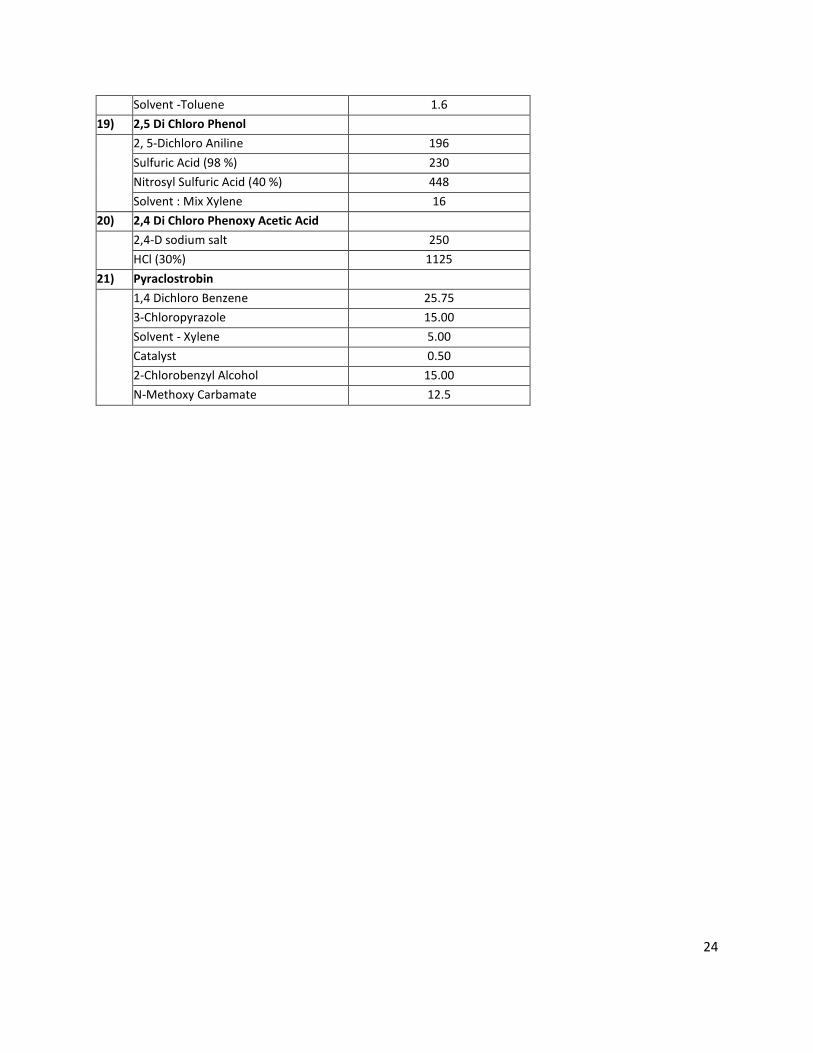
Solvent -Toluene 1.6
19) 2,5 Di Chloro Phenol
2, 5-Dichloro Aniline 196
Sulfuric Acid (98 %) 230
Nitrosyl Sulfuric Acid (40 %) 448
Solvent : Mix Xylene 16
20) 2,4 Di Chloro Phenoxy Acetic Acid
2,4-D sodium salt 250
HCl (30%) 1125
21) Pyraclostrobin
1,4 Dichloro Benzene 25.75
3-Chloropyrazole 15.00
Solvent - Xylene 5.00
Catalyst 0.50
2-Chlorobenzyl Alcohol 15.00
N-Methoxy Carbamate 12.5
25
ANNEXURE: 3
BRIEF MANUFACTRING PROCESS, CHEMICAL REACTION AND MASS BALANCE WITH FLOW DIAGRAM
1) META PHENOXY BENZALDEHYDE (ORGANIC INTERMEDIATE) (EXISTING)
PROCESS DESCRIPTION
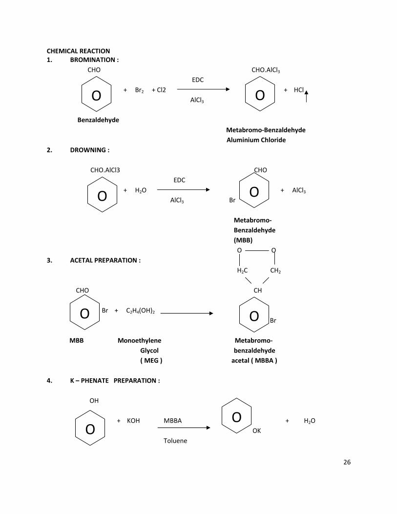
Metabromobenzaldehyde (MBB) Preparation:-
Benzaldehyde is reacted with Chlorine and Bromine in the presence of EDC (as solvent) and Aluminium
Chloride as catalyst .Then the reaction mass is drowned in chilled water containing HCl and Formic acid ;
and then washed with Sodium Thiosulphate solution . Crude MBB, thus obtained is further purified by
distillation.
Metabromobenzaldehyde Acetal (MBBA) Preparation:-
MBB is reacted with MEG in the presence of PTSA (as catalyst) and Water formed is distilled off and pure
MBBA is obtained.
Metaphenoxybenzaldehyde Acetal (MPBA) Preparation:-
First, Potassium Phenoxide is prepared by reacting Phenol with Potassium Hydroxide (KOH) in presence
of Toluene .Then Potassium Phenoxide is reacted with MBBA and MPBA is formed. Crude MPBA is
purified by Water washings.
Hydrolysis:-
MPBA is hydrolyzed to MPB in presence of Water and Sulphuric acid. Crude MEG so obtained is purified
by distillation and recycled to MBBA preparation. The crude MPB is sent for final Purification.
MPB Distillation / Purification:-
The crude MPB is subjected to high vacuum distillation and pure MPB is obtained, which is packed as
Finished Product.
26
CHEMICAL REACTION
1. BROMINATION :
CHO CHO.AlCl3
EDC
+ Br2 + Cl2 + HCl
AlCl3 Br
Benzaldehyde
Metabromo-Benzaldehyde
Aluminium Chloride
2. DROWNING :
CHO.AlCl3 CHO
EDC
+ H2O + AlCl3
AlCl3 Br Br
Metabromo-
Benzaldehyde
(MBB)
O O
3. ACETAL PREPARATION :
H2C CH2
CHO CH
Br + C2H4(OH)2 + H2O
Br
MBB Monoethylene Metabromo-
Glycol benzaldehyde
( MEG ) acetal ( MBBA )
4. K – PHENATE PREPARATION :
OH
+ KOH MBBA + H2O
OK
Toluene
O O
O
O O
O
O O
27
Phenol Potassium Potassium
Hydroxide Phenoxide
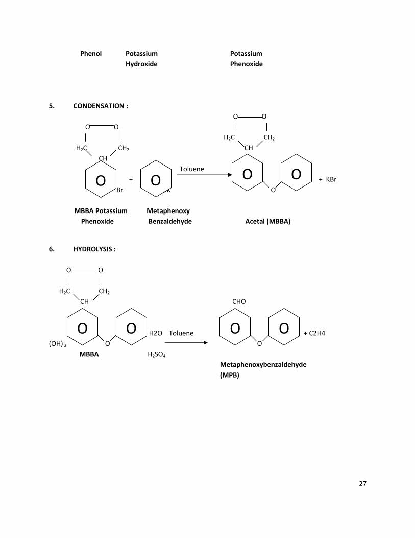
5. CONDENSATION :
O O
O O
H2C CH2
H2C CH2 CH
CH
Toluene
+ + KBr
Br OK O
MBBA Potassium Metaphenoxy
Phenoxide Benzaldehyde Acetal (MBBA)
6. HYDROLYSIS :
O O
H2C CH2
CH CHO
+ H2O Toluene + C2H4
(OH) 2 O O
MBBA H2SO4
Metaphenoxybenzaldehyde
(MPB)
O O O O
O O O O
28
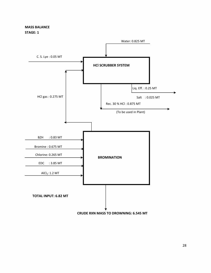
MASS BALANCE
STAGE: 1
Water: 0.825 MT
C. S. Lye : 0.05 MT
Liq. Eff. : 0.25 MT
BZH : 0.83 MT
Bromine : 0.675 MT
Chlorine: 0.265 MT
EDC : 3.85 MT
AlCl3: 1.2 MT
TOTAL INPUT: 6.82 MT
BROMINATION
CRUDE RXN MASS TO DROWNING: 6.545 MT
HCl SCRUBBER SYSTEM
HCl gas : 0.275 MT
Salt : 0.025 MT
Rec. 30 % HCl : 0.875 MT
(To be used in Plant)
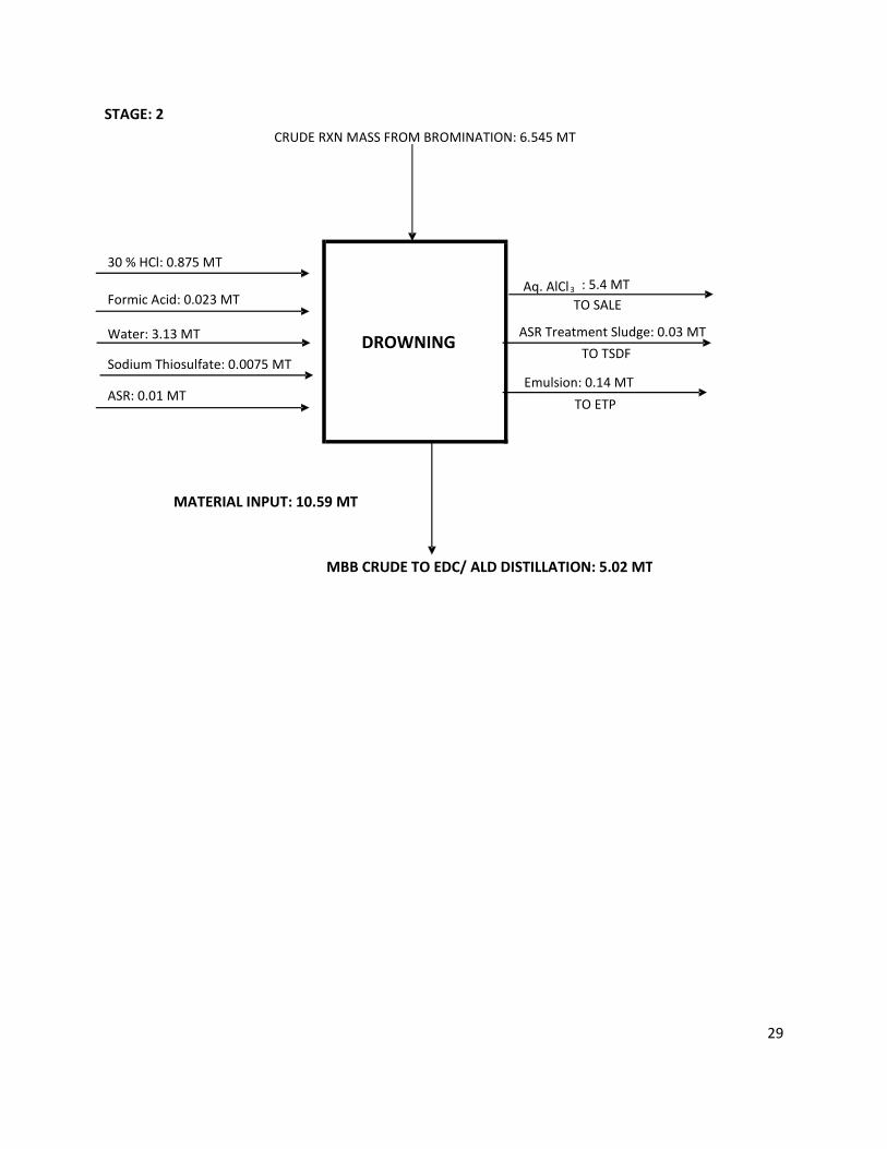
29
STAGE: 2
30 % HCl: 0.875 MT
Formic Acid: 0.023 MT TO SALE
Water: 3.13 MT
Sodium Thiosulfate: 0.0075 MT
ASR: 0.01 MT
MATERIAL INPUT: 10.59 MT
MBB CRUDE TO EDC/ ALD DISTILLATION: 5.02 MT
CRUDE RXN MASS FROM BROMINATION: 6.545 MT
TO ETP
DROWNING
Aq. AlCl3 : 5.4 MT
ASR Treatment Sludge: 0.03 MT
Emulsion: 0.14 MT
TO TSDF
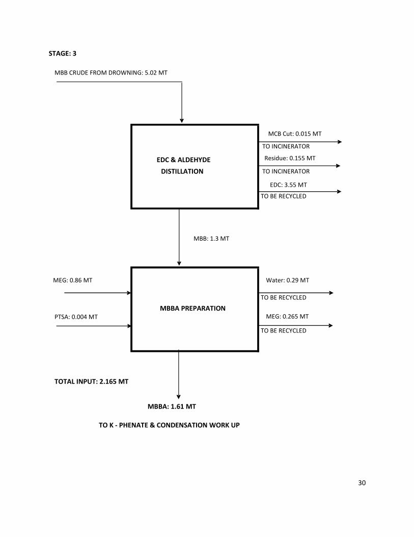
30
STAGE: 3
MCB Cut: 0.015 MT
Residue: 0.155 MT
EDC: 3.55 MT
Water: 0.29 MT
PTSA: 0.004 MT MEG: 0.265 MT
TOTAL INPUT: 2.165 MT
MBB: 1.3 MT
MEG: 0.86 MT
MBBA PREPARATION
TO BE RECYCLED
TO BE RECYCLED
MBB CRUDE FROM DROWNING: 5.02 MT
EDC & ALDEHYDE
DISTILLATION
TO INCINERATOR
TO INCINERATOR
TO BE RECYCLED
MBBA: 1.61 MT
TO K - PHENATE & CONDENSATION WORK UP
31
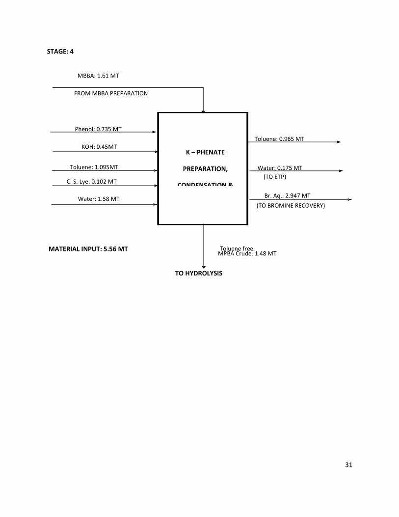
STAGE: 4
Toluene: 0.965 MT
Toluene: 1.095MT Water: 0.175 MT
C. S. Lye: 0.102 MT
Br. Aq.: 2.947 MT
MATERIAL INPUT: 5.56 MT MPBA Crude: 1.48 MT
TO HYDROLYSIS
Toluene free
FROM MBBA PREPARATION
K – PHENATE
PREPARATION,
CONDENSATION &
Phenol: 0.735 MT
KOH: 0.45MT
(TO ETP)
Water: 1.58 MT (TO BROMINE RECOVERY)
MBBA: 1.61 MT
32
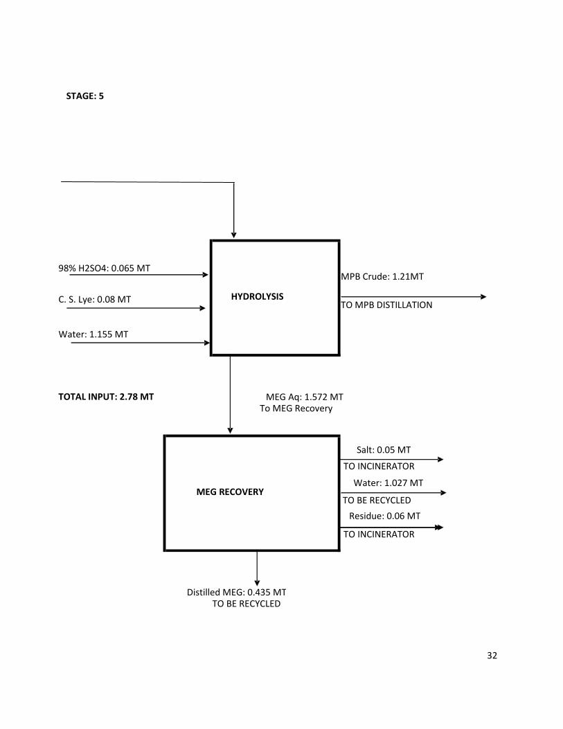
STAGE: 5
98% H2SO4: 0.065 MT MPB Crude: 1.21MT
C. S. Lye: 0.08 MTTO MPB DISTILLATION
Water: 1.155 MT
TOTAL INPUT: 2.78 MT MEG Aq: 1.572 MT To MEG Recovery
MEG RECOVERY
Residue: 0.06 MT
TO INCINERATOR
HYDROLYSIS
Salt: 0.05 MT
TO INCINERATOR
Water: 1.027 MT
TO BE RECYCLED
Distilled MEG: 0.435 MT TO BE RECYCLED
33
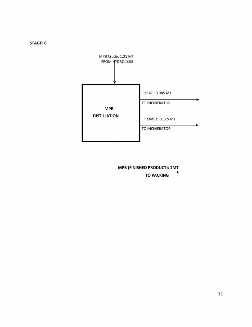
STAGE: 6
1st I/C: 0.085 MT
Residue: 0.125 MT
MPB (FINISHED PRODUCT): 1MT
TO PACKING
FROM HYDROLYSIS
MPB
DISTILLATION
TO INCINERATOR
TO INCINERATOR
MPB Crude: 1.21 MT
34
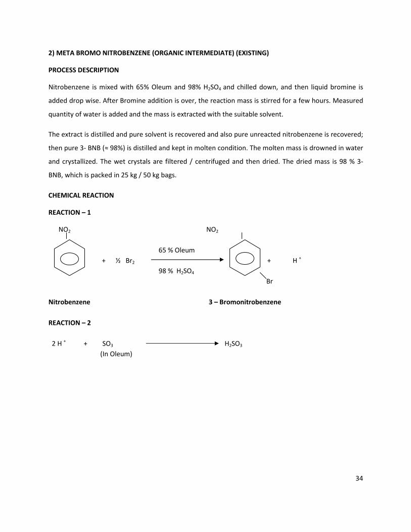
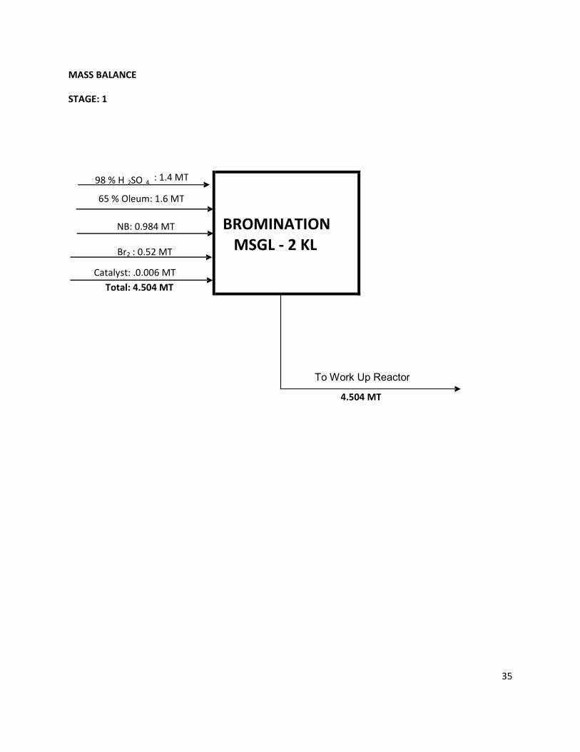
2) META BROMO NITROBENZENE (ORGANIC INTERMEDIATE) (EXISTING)
PROCESS DESCRIPTION
Nitrobenzene is mixed with 65% Oleum and 98% H2SO4 and chilled down, and then liquid bromine is
added drop wise. After Bromine addition is over, the reaction mass is stirred for a few hours. Measured
quantity of water is added and the mass is extracted with the suitable solvent.
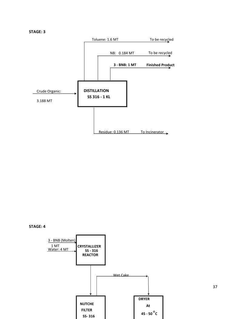
The extract is distilled and pure solvent is recovered and also pure unreacted nitrobenzene is recovered;
then pure 3- BNB (≈ 98%) is distilled and kept in molten condition. The molten mass is drowned in water
and crystallized. The wet crystals are filtered / centrifuged and then dried. The dried mass is 98 % 3-
BNB, which is packed in 25 kg / 50 kg bags.
CHEMICAL REACTION
REACTION – 1
NO2 NO2
65 % Oleum
+ ½ Br2 + H +
98 % H2SO4
Br
Nitrobenzene 3 – Bromonitrobenzene
REACTION – 2
2 H + + SO3 H2SO3
(In Oleum)
35
MASS BALANCE
STAGE: 1
4.504 MT
BROMINATION
MSGL - 2 KL
To Work Up Reactor
98 % H 2SO 4 : 1.4 MT
Total: 4.504 MT
65 % Oleum: 1.6 MT
NB: 0.984 MT
Br 2 : 0.52 MT
Catalyst: .0.006 MT

36
Organic Organic
Lean Acidic
H2 SO
4 Water
Wash
Org.: 3.316 MT
Next batch
To ETP
Org.: 3.268 MT
Extracted Aqueous: 4.056 MT Final Org.: 3.188 MT
To Distillation
Aqueous: 4.088 MT
(Conc. 67 % H2 SO
4 )To Sale
Acidic Aq.: 3.304 MT
To be Recycled
ORGANIC
HOLD TANK
3.316 MT
C. S. Lye: 0.076 MT Organic: 3.268 MT+
Organic: 3.316 MT
AQUEOUS
HOLD TANK
4.088 MT
EXTRACTED
TOLUENE
1.72 MT
Weak Acidic Aq. Acidic Aq.
AQUEOUS:
(3.304 MT)
Avg. Sp. Gr.: 1.02
WORK UP
(MSGL)
2KL
Water: 4.4 MT
Toluene (R): 3.44 MT
STAGE: 2
37
STAGE: 3
STAGE: 4
Finished Product
To be recycled
To Incinerator
NB: 0.184 MT
3 - BNB: 1 MT
Residue: 0.136 MT
DISTILLATION
SS 316 - 1 KL
Crude Organic:
3.188 MT
3 - BNB (Molten)
Water: 4 MT1 MT CRYSTALLIZER
SS - 316 REACTOR
Wet Cake
NUTCHE
FILTER
SS- 316
DRYER
At
45 - 50O
C
SS-316
To be recycled Toluene: 1.6 MT
38
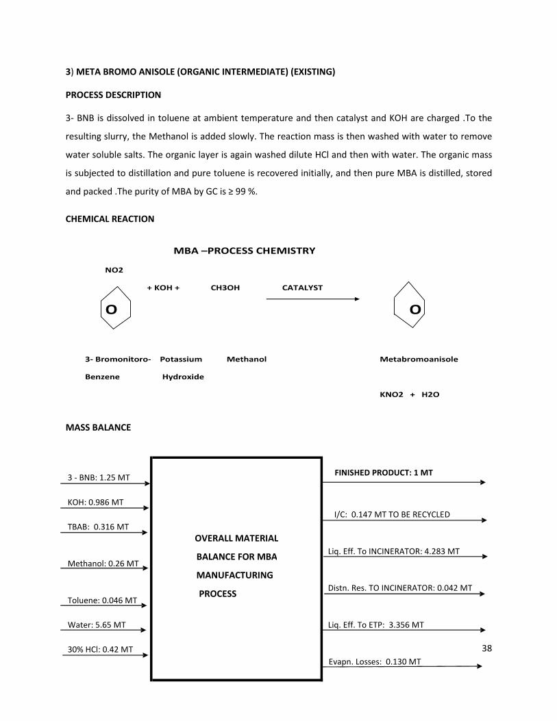
MBA –PROCESS CHEMISTRY
NO2
+ KOH + CH3OH CATALYST
O O
3- Bromonitoro- Potassium Methanol Metabromoanisole
Benzene Hydroxide
KNO2 + H2O
3) META BROMO ANISOLE (ORGANIC INTERMEDIATE) (EXISTING)
PROCESS DESCRIPTION
3- BNB is dissolved in toluene at ambient temperature and then catalyst and KOH are charged .To the
resulting slurry, the Methanol is added slowly. The reaction mass is then washed with water to remove
water soluble salts. The organic layer is again washed dilute HCl and then with water. The organic mass
is subjected to distillation and pure toluene is recovered initially, and then pure MBA is distilled, stored
and packed .The purity of MBA by GC is ≥ 99 %.
CHEMICAL REACTION
MASS BALANCE
3 - BNB: 1.25 MT
KOH: 0.986 MT
TBAB: 0.316 MT
Methanol: 0.26 MT
Toluene: 0.046 MT
Water: 5.65 MT Liq. Eff. To ETP: 3.356 MT
30% HCl: 0.42 MT
OVERALL MATERIAL
BALANCE FOR MBA
MANUFACTURING
PROCESS
FINISHED PRODUCT: 1 MT
Liq. Eff. To INCINERATOR: 4.283 MT
Distn. Res. TO INCINERATOR: 0.042 MT
Evapn. Losses: 0.130 MT
I/C: 0.147 MT TO BE RECYCLED
39
4) LAMBDA CYHALOTHRIN or DELTAMETHRIN (PESTICIDE) (EXISTING)
A. LAMBDA CYHALOTHRIN
MANUFACTURING PROCESS
The process for the manufacturing of λ – Cyhalothrin is divided into the following steps:
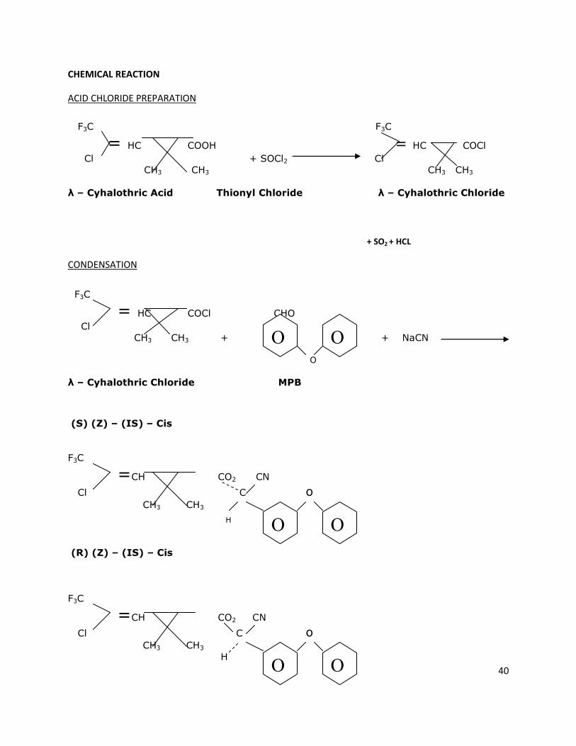
1. ACID CHLORIDE PREPARATION
λ – Cyhalothric acid is reacted with Thionyl Chloride in presence of n-Hexane (as solvent ) at low
temperature over a period of time .The SO2 and HCl gas are liberated slowly as the reaction progresses;
and , first HCl gas is scrubbed in water and then SO2 is scrubbed by NaOH solution. The resulting 30 %
HCl solution and also Sodium Bisulfite are obtained in the scrubbing system .After the reaction, Hexane
is distilled off and recycled back to the next batch. The resulting Acid Chloride is sent for the
Condensation step.
2. CONDENSATION & WORK – UP
In the solution of water and Sodium Cyanide, MPB and Acid Chloride are added at low temperature.
After the addition, the reaction mass is cooled at low temperature for the fixed period. Then phase
separation carried out and the organic phase washed with hypo & alkali solution. The organic phase is
subjected to distillation at low temperature to remove Hexane which is recycled. Hexane – free reaction
mass which is Crude λ – Cyhalothrin is sent for the Epimerisation step. The aqueous phase is sent for
Cyanide Effluent Treatment.
3. EPIMERISATION & IPA RECOVERY
The crude λ – Cyhalothrin is washed with IPA and DIIPA in presence of solvent. Then again washed with
acidic water .The phases are separated .The IPA & Hexane are recovered and the reaction mass sent for
crystallization.
4. CRYSTALLIZATION
THE EPIMERIZED MASS IS EXTRACTED WITH THE SOLVENT AND THEN DRIED. THE DRIED MASS WHICH
IS Λ – CYHALOTHRIN IS PACKED.
40
F3C F3C
= HC COOH = HC COCl
Cl + SOCl2 Cl
CH3 CH3 CH3 CH3
λ – Cyhalothric Acid Thionyl Chloride λ – Cyhalothric Chloride
F3C
= HC COCl CHO
Cl
CH3 CH3 + + NaCN
O
λ – Cyhalothric Chloride MPB
(S) (Z) – (IS) – Cis
F3C
=CH CO2 CN Cl C o
CH3 CH3
H
(R) (Z) – (IS) – Cis
F3C
=CH CO2 CN Cl C o
CH3 CH3
H
O O
O O
O O
CHEMICAL REACTION
ACID CHLORIDE PREPARATION
+ SO2 + HCL
CONDENSATION
41
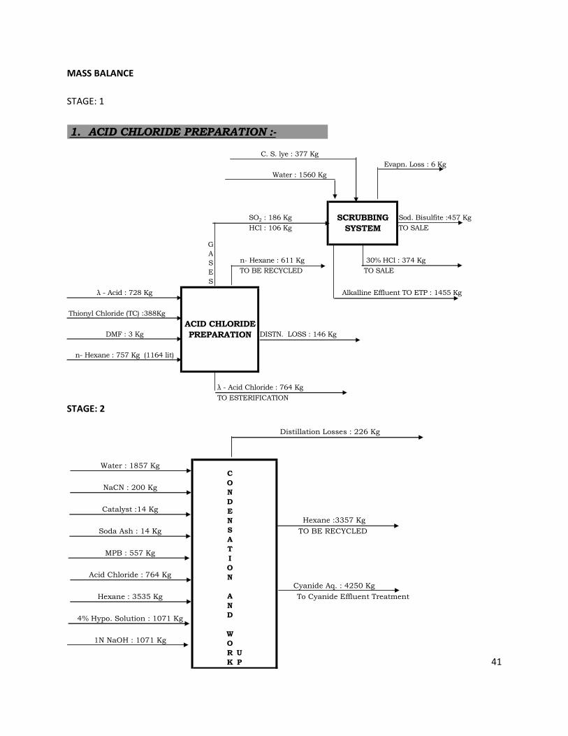
Sod. Bisulfite :457 Kg
TO SALE
30% HCl : 374 Kg
TO SALE
Thionyl Chloride (TC) :388Kg
DISTN. LOSS : 146 Kg
λ - Acid Chloride : 764 Kg
TO ESTERIFICATION
1. ACID CHLORIDE PREPARATION :-
G
A
S
E
S
Water : 1560 Kg
SO2 : 186 Kg
HCl : 106 Kg
n- Hexane : 757 Kg (1164 lit)
C. S. lye : 377 Kg
DMF : 3 Kg
λ - Acid : 728 Kg
SCRUBBING
SYSTEM
ACID CHLORIDE
PREPARATION
Evapn. Loss : 6 Kg
Alkalline Effluent TO ETP : 1455 Kg
TO BE RECYCLED
n- Hexane : 611 Kg
C
O
N
D
E
N
S
A
T
I
O
N
A
N
D
W
O
R
K
U
P
Cyanide Aq. : 4250 Kg
To Cyanide Effluent Treatment
Hexane :3357 Kg
TO BE RECYCLED
Distillation Losses : 226 Kg
Water : 1857 Kg
NaCN : 200 Kg
Catalyst :14 Kg
Soda Ash : 14 Kg
1N NaOH : 1071 Kg
MPB : 557 Kg
Acid Chloride : 764 Kg
Hexane : 3535 Kg
4% Hypo. Solution : 1071 Kg
MASS BALANCE
STAGE: 1
STAGE: 2
42
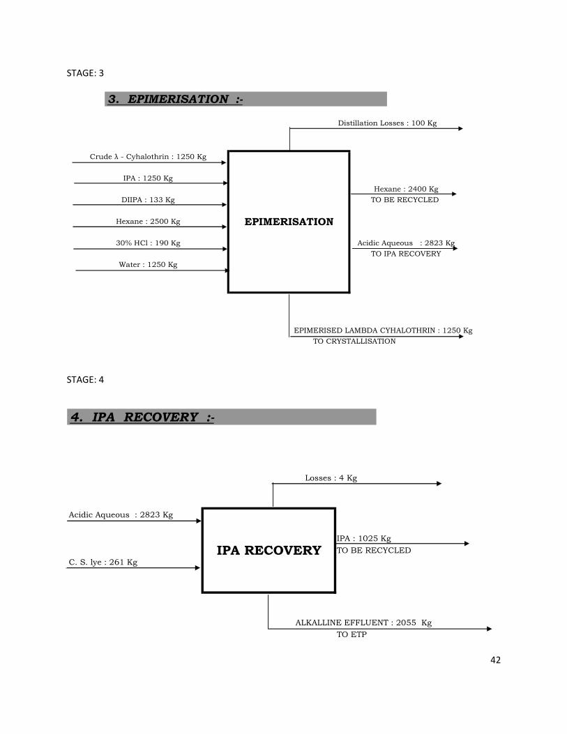
TO CRYSTALLISATION
EPIMERISED LAMBDA CYHALOTHRIN : 1250 Kg
Water : 1250 Kg
30% HCl : 190 Kg
Hexane : 2500 Kg
Acidic Aqueous : 2823 Kg
TO IPA RECOVERY
3. EPIMERISATION :-
EPIMERISATION
Crude λ - Cyhalothrin : 1250 Kg
DIIPA : 133 Kg
IPA : 1250 Kg
Distillation Losses : 100 Kg
Hexane : 2400 Kg
TO BE RECYCLED
Acidic Aqueous : 2823 Kg
IPA : 1025 Kg
TO BE RECYCLED
C. S. lye : 261 Kg
ALKALLINE EFFLUENT : 2055 Kg
TO ETP
4. IPA RECOVERY :-
Losses : 4 Kg
IPA RECOVERY
STAGE: 3
STAGE: 4
43
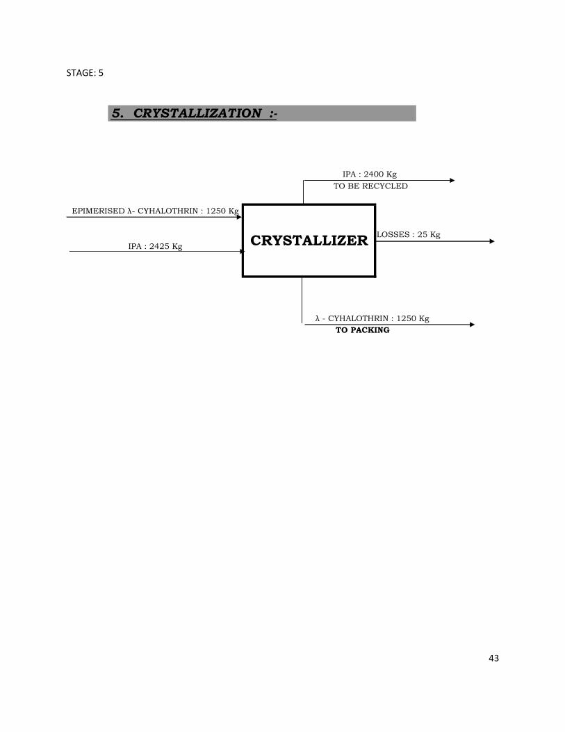
LOSSES : 25 Kg
TO PACKING
λ - CYHALOTHRIN : 1250 Kg
EPIMERISED λ- CYHALOTHRIN : 1250 Kg
IPA : 2425 Kg
5. CRYSTALLIZATION :-
CRYSTALLIZER
IPA : 2400 Kg
TO BE RECYCLED
STAGE: 5
44
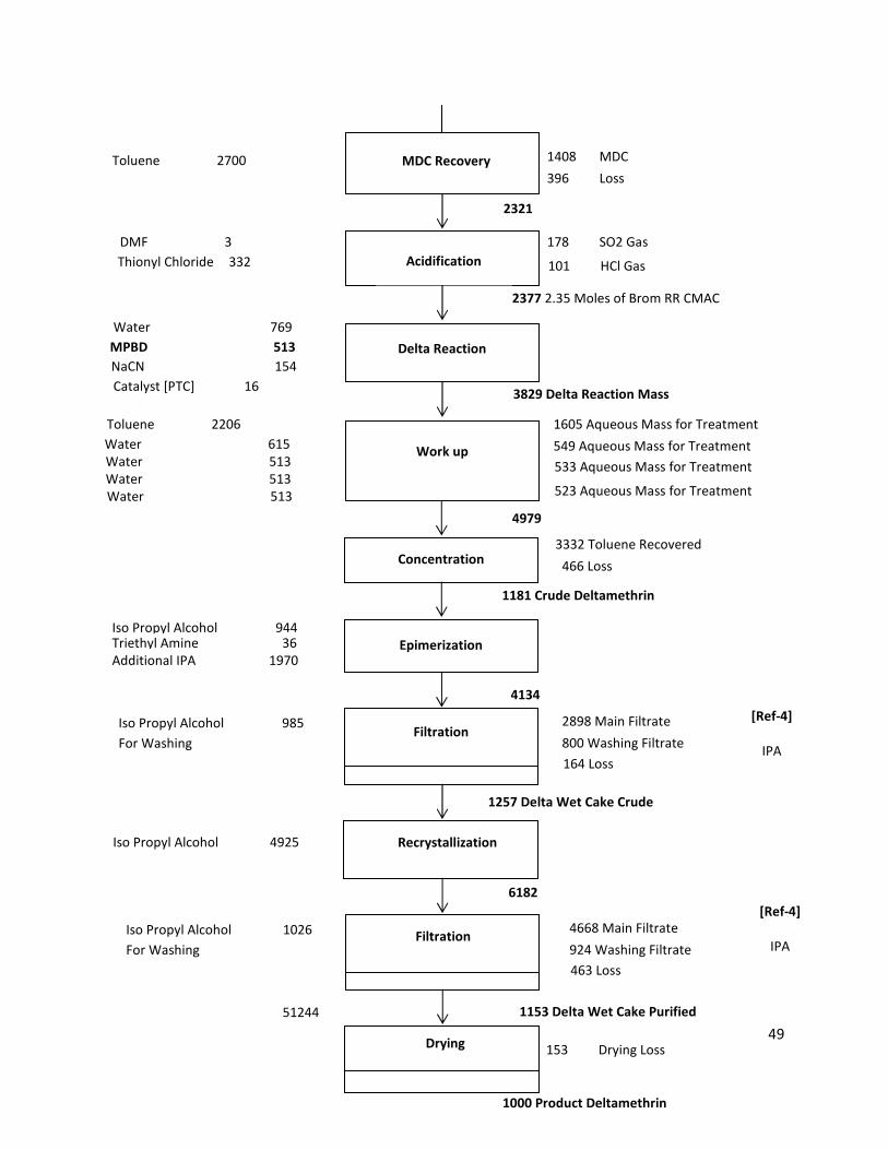
B. DELTAMETHRIN
PROCESS DESCRIPTION
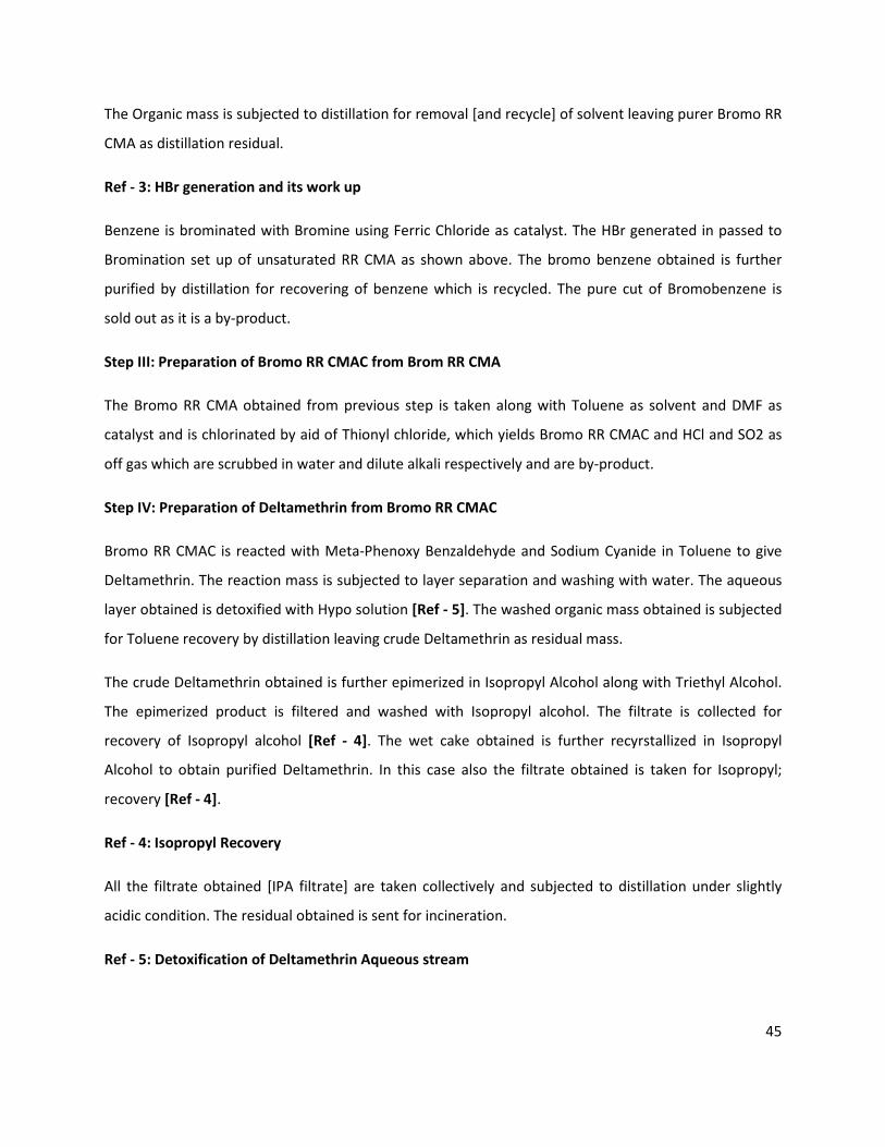
Step I: Resolution of Mix CMA to RR CMA
Mix CMA [SS CMA and RR CMA] is converted to its sodium salt along with Catalyst EPH. The RR CMA
sodium salt along with EPH precipitates under alkaline condition, while SS CMA remains soluble in the
aqueous medium. The precipitates are filtered and wash with water. The filtrates are collected and
worked up for recovery of SS CMA [Ref - 2].
The solids [wet cake of RR CMA Sodium salt along with EPH] is further taken in solvent MDC along with
water and acidified to pH 2 by HCl solution. The RR CMA gets extracted in MDC while EPH in aqueous
medium. The layers are separated. The aqueous [main separation] is collected separately for catalyst
recovery and recycle [Ref - 1]. The Organic layer is further washed with water and taken for further
process. The washing water is taken to ETP.
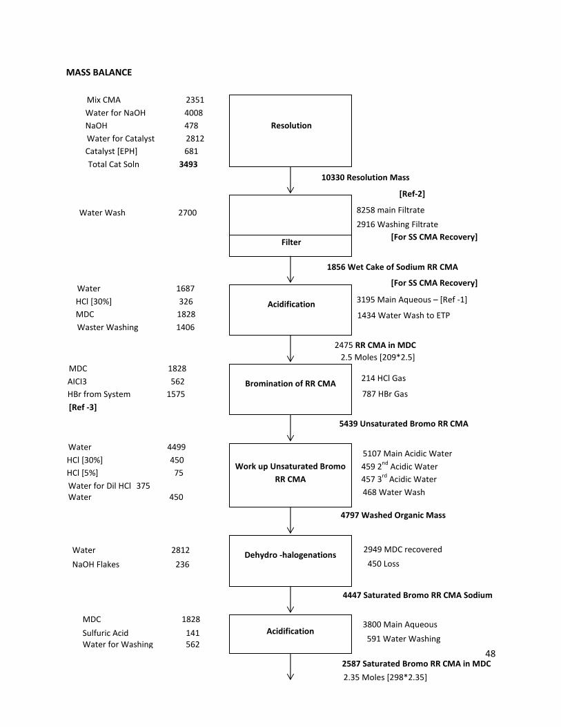
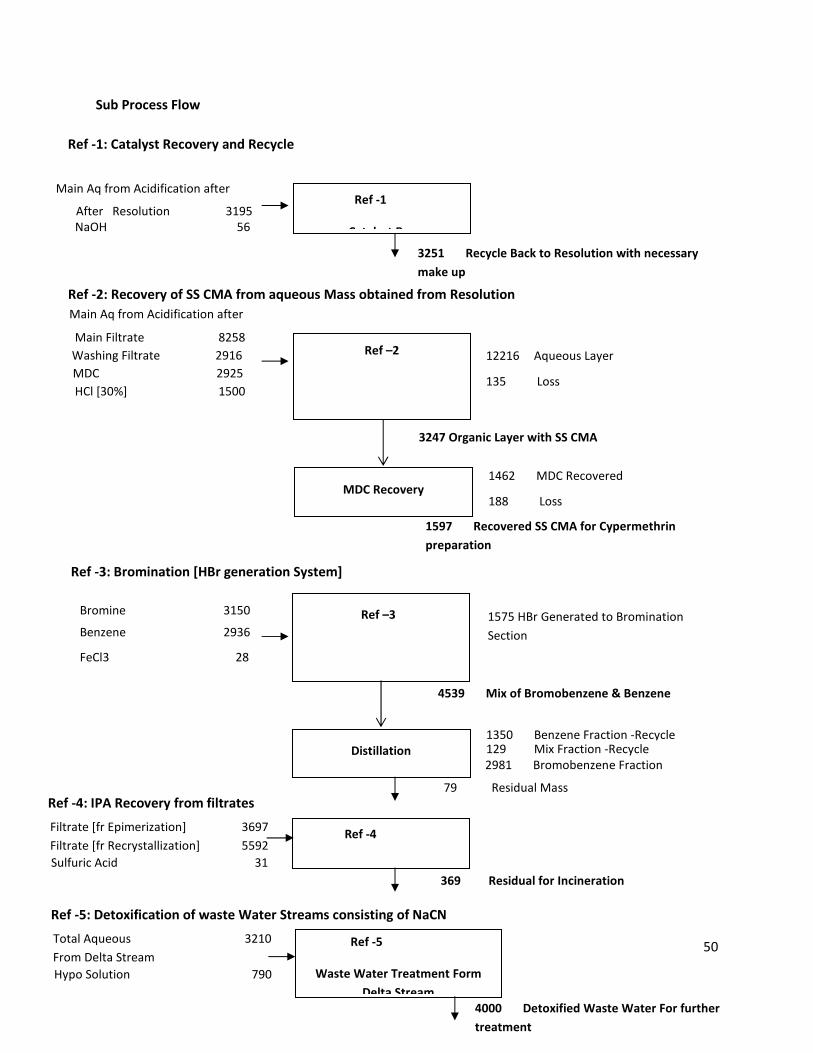
Ref - 1: Recovery of Catalyst
The main aqueous layer obtained from acidification of RR CMA sodium is further adjusted for its pH to
3.5 - 4.0 by NaOH and is directly recycled as Catalyst with necessary make up.
Ref - 2: Recovery of SS CMA
The highly alkaline aqueous filtrates from step I is taken along with Solvent MDC and acidified by HCl
solution. The SS CMA thus formed is extracted in MDC. The layers are separated. The acidic aqueous
layer is taken for treatment, while organic layer is further subjected to MDC distillation [initially under
atmospheric condition followed by vacuum recovery]. The residual molten mass is SS CMA and is used
for Cypermethrin manufacturing.
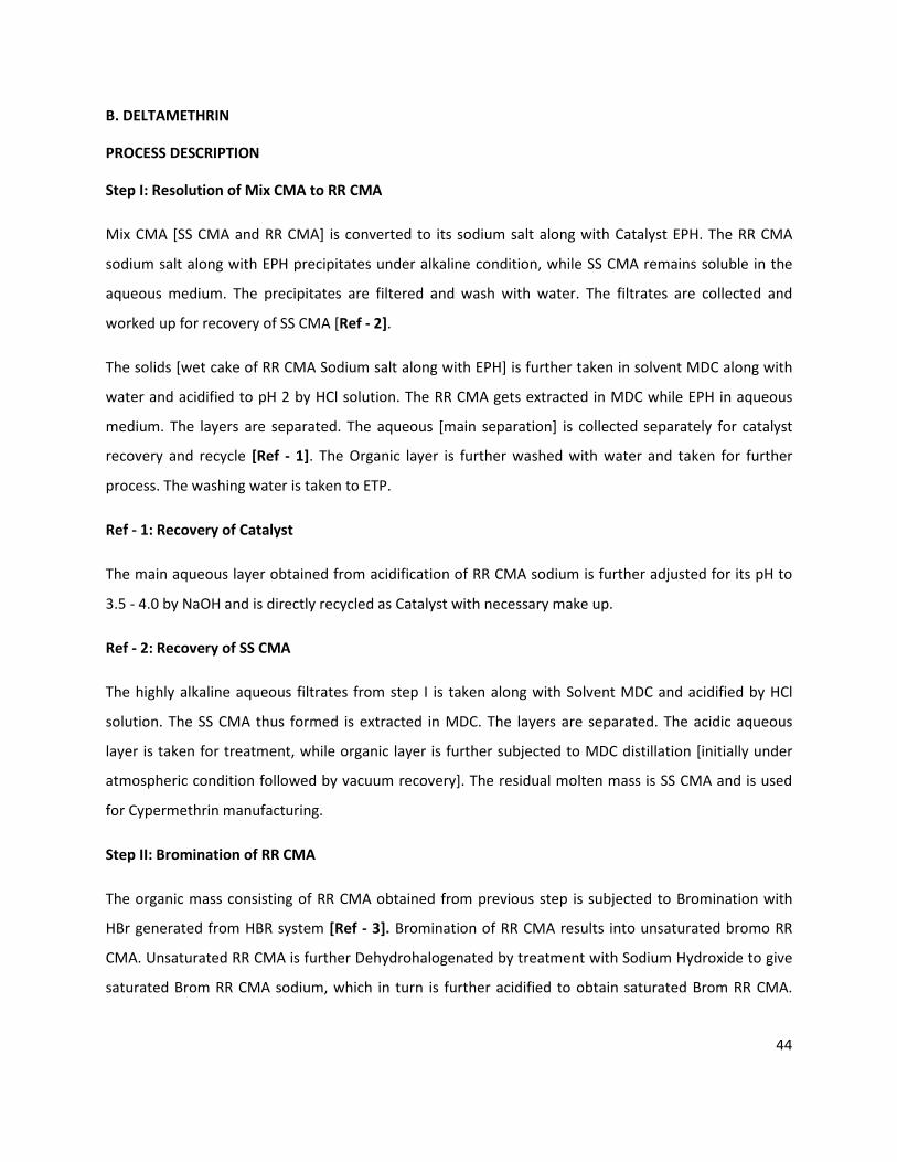
Step II: Bromination of RR CMA
The organic mass consisting of RR CMA obtained from previous step is subjected to Bromination with
HBr generated from HBR system [Ref - 3]. Bromination of RR CMA results into unsaturated bromo RR
CMA. Unsaturated RR CMA is further Dehydrohalogenated by treatment with Sodium Hydroxide to give
saturated Brom RR CMA sodium, which in turn is further acidified to obtain saturated Brom RR CMA.
45
The Organic mass is subjected to distillation for removal [and recycle] of solvent leaving purer Bromo RR
CMA as distillation residual.
Ref - 3: HBr generation and its work up
Benzene is brominated with Bromine using Ferric Chloride as catalyst. The HBr generated in passed to
Bromination set up of unsaturated RR CMA as shown above. The bromo benzene obtained is further
purified by distillation for recovering of benzene which is recycled. The pure cut of Bromobenzene is
sold out as it is a by-product.
Step III: Preparation of Bromo RR CMAC from Brom RR CMA
The Bromo RR CMA obtained from previous step is taken along with Toluene as solvent and DMF as
catalyst and is chlorinated by aid of Thionyl chloride, which yields Bromo RR CMAC and HCl and SO2 as
off gas which are scrubbed in water and dilute alkali respectively and are by-product.
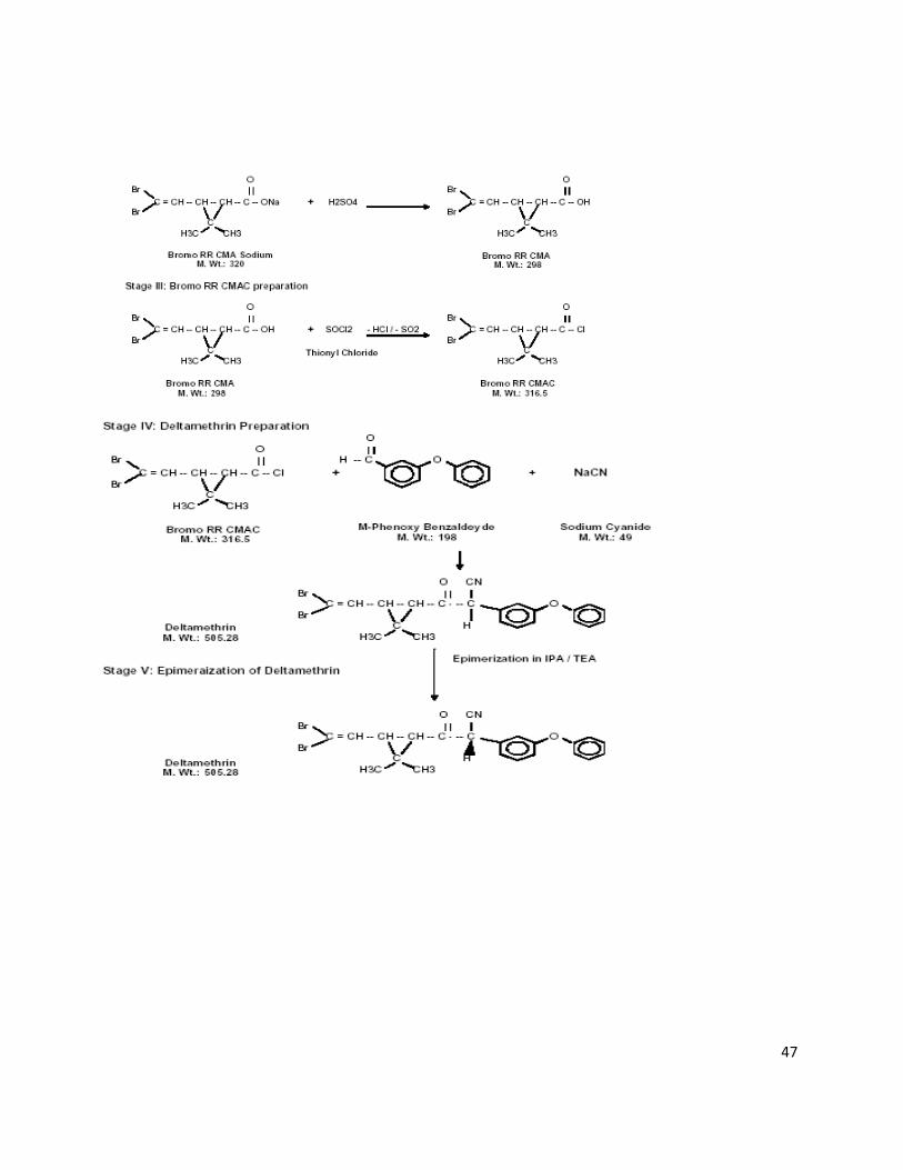
Step IV: Preparation of Deltamethrin from Bromo RR CMAC
Bromo RR CMAC is reacted with Meta-Phenoxy Benzaldehyde and Sodium Cyanide in Toluene to give
Deltamethrin. The reaction mass is subjected to layer separation and washing with water. The aqueous
layer obtained is detoxified with Hypo solution [Ref - 5]. The washed organic mass obtained is subjected
for Toluene recovery by distillation leaving crude Deltamethrin as residual mass.
The crude Deltamethrin obtained is further epimerized in Isopropyl Alcohol along with Triethyl Alcohol.
The epimerized product is filtered and washed with Isopropyl alcohol. The filtrate is collected for
recovery of Isopropyl alcohol [Ref - 4]. The wet cake obtained is further recyrstallized in Isopropyl
Alcohol to obtain purified Deltamethrin. In this case also the filtrate obtained is taken for Isopropyl;
recovery [Ref - 4].
Ref - 4: Isopropyl Recovery
All the filtrate obtained [IPA filtrate] are taken collectively and subjected to distillation under slightly
acidic condition. The residual obtained is sent for incineration.
Ref - 5: Detoxification of Deltamethrin Aqueous stream

46
TOTAL AQUEOUS MASS OBTAINED FROM DELTAMETHRIN REACTION STREAM IS COLLECTIVELY DE-
TOXIFIED USING HYPO SOLUTION.
CHEMICAL REACTION
47
48
MASS BALANCE
Mix CMA 2351
Water for NaOH 4008
NaOH 478
Water for Catalyst 2812
Catalyst [EPH] 681
Total Cat Soln 3493
Resolution
Filter
Acidification
Bromination of RR CMA
Work up Unsaturated Bromo
RR CMA
10330 Resolution Mass
[Ref-2]
8258 main Filtrate
2916 Washing Filtrate
[For SS CMA Recovery]
1856 Wet Cake of Sodium RR CMA
[For SS CMA Recovery]
3195 Main Aqueous – [Ref -1]
1434 Water Wash to ETP
2475 RR CMA in MDC
2.5 Moles [209*2.5]
Water Wash 2700
Water 1687
HCl [30%] 326
MDC 1828
Waster Washing 1406
MDC 1828
AICI3 562
HBr from System 1575
[Ref -3]
Water 4499
HCl [30%] 450
HCl [5%] 75
Water for Dil HCl 375
Water 450
Dehydro -halogenations
Acidification
214 HCl Gas
787 HBr Gas
5439 Unsaturated Bromo RR CMA
5107 Main Acidic Water
459 2nd
Acidic Water
457 3rd
Acidic Water
468 Water Wash
4797 Washed Organic Mass
2949 MDC recovered
450 Loss
Water 2812
NaOH Flakes 236
MDC 1828
Sulfuric Acid 141
4447 Saturated Bromo RR CMA Sodium
3800 Main Aqueous
591 Water Washing
2587 Saturated Bromo RR CMA in MDC
2.35 Moles [298*2.35]
Water for Washing 562
49
153 Drying Loss
1000 Product Deltamethrin
51244
Drying
Acidification
Delta Reaction
Work up
1408 MDC
396 Loss
2321
178 SO2 Gas
101 HCl Gas
2377 2.35 Moles of Brom RR CMAC
Toluene 2700
Water 769
MPBD 513
NaCN 154
Catalyst [PTC] 16
DMF 3
Thionyl Chloride 332
Toluene 2206
Water 615
Concentration
1605 Aqueous Mass for Treatment
4979
3332 Toluene Recovered
466 Loss
Iso Propyl Alcohol 944 Triethyl Amine 36
1181 Crude Deltamethrin
4134
Additional IPA 1970
MDC Recovery
3829 Delta Reaction Mass
Water 513
Water 513
Water 513
549 Aqueous Mass for Treatment
533 Aqueous Mass for Treatment
523 Aqueous Mass for Treatment
Epimerization
Filtration
Recrystallization
Filtration
2898 Main Filtrate
800 Washing Filtrate
164 Loss
1257 Delta Wet Cake Crude
6182
Iso Propyl Alcohol 4925
Iso Propyl Alcohol 985
For Washing
4668 Main Filtrate
924 Washing Filtrate
463 Loss
1153 Delta Wet Cake Purified
Iso Propyl Alcohol 1026
For Washing
[Ref-4]
IPA
Recovery
[Ref-4]
IPA
Recovery
50
Sub Process Flow
Ref -1
Catalyst Recovery
3251 Recycle Back to Resolution with necessary
make up
Main Filtrate 8258
Washing Filtrate 2916
MDC 2925
HCl [30%] 1500
1575 HBr Generated to Bromination
Section
Bromine 3150
Benzene 2936
4539 Mix of Bromobenzene & Benzene
FeCl3 28
Ref -1: Catalyst Recovery and Recycle
Main Aq from Acidification after
After Resolution 3195
NaOH 56
Ref -2: Recovery of SS CMA from aqueous Mass obtained from Resolution
Main Aq from Acidification after
Ref –2
12216 Aqueous Layer
135 Loss
3247 Organic Layer with SS CMA
MDC Recovery
1597 Recovered SS CMA for Cypermethrin
preparation
1462 MDC Recovered
188 Loss
Ref -3: Bromination [HBr generation System]
Ref –3
Distillation
79 Residual Mass
1350 Benzene Fraction -Recycle 129 Mix Fraction -Recycle
2981 Bromobenzene Fraction
Ref -4
IPA Recovery 369 Residual for Incineration
Ref -4: IPA Recovery from filtrates
Filtrate [fr Epimerization] 3697
Filtrate [fr Recrystallization] 5592
Sulfuric Acid 31
Ref -5
Waste Water Treatment Form
Delta Stream
4000 Detoxified Waste Water For further
treatment
Ref -5: Detoxification of waste Water Streams consisting of NaCN
Total Aqueous 3210
From Delta Stream
Hypo Solution 790
51
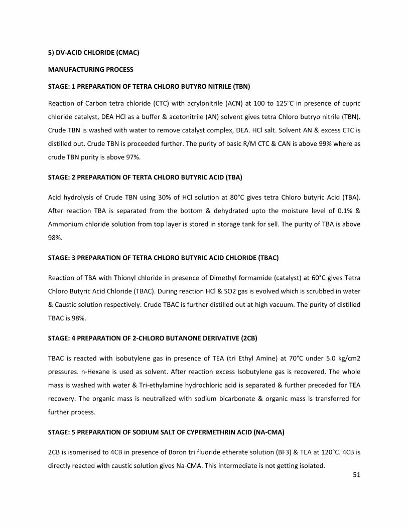
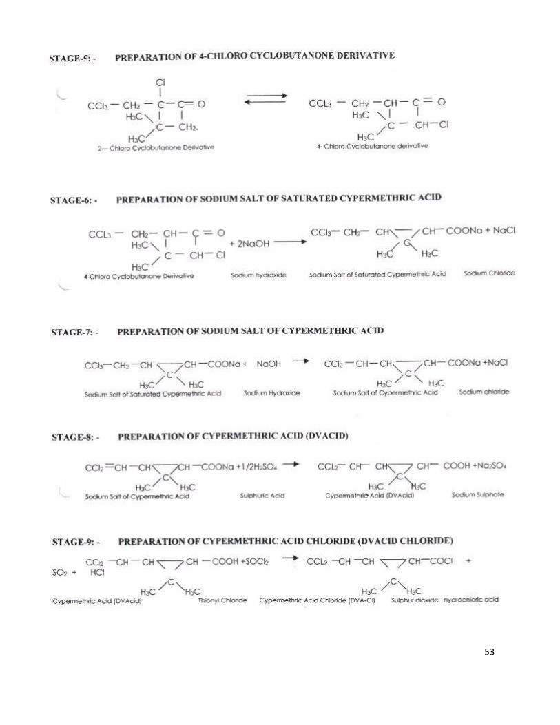
5) DV-ACID CHLORIDE (CMAC)
MANUFACTURING PROCESS
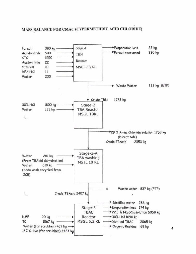
STAGE: 1 PREPARATION OF TETRA CHLORO BUTYRO NITRILE (TBN)
Reaction of Carbon tetra chloride (CTC) with acrylonitrile (ACN) at 100 to 125°C in presence of cupric
chloride catalyst, DEA HCl as a buffer & acetonitrile (AN) solvent gives tetra Chloro butryo nitrile (TBN).
Crude TBN is washed with water to remove catalyst complex, DEA. HCl salt. Solvent AN & excess CTC is
distilled out. Crude TBN is proceeded further. The purity of basic R/M CTC & CAN is above 99% where as
crude TBN purity is above 97%.
STAGE: 2 PREPARATION OF TERTA CHLORO BUTYRIC ACID (TBA)
Acid hydrolysis of Crude TBN using 30% of HCl solution at 80°C gives tetra Chloro butyric Acid (TBA).
After reaction TBA is separated from the bottom & dehydrated upto the moisture level of 0.1% &
Ammonium chloride solution from top layer is stored in storage tank for sell. The purity of TBA is above
98%.
STAGE: 3 PREPARATION OF TETRA CHLORO BUTYRIC ACID CHLORIDE (TBAC)
Reaction of TBA with Thionyl chloride in presence of Dimethyl formamide (catalyst) at 60°C gives Tetra
Chloro Butyric Acid Chloride (TBAC). During reaction HCl & SO2 gas is evolved which is scrubbed in water
& Caustic solution respectively. Crude TBAC is further distilled out at high vacuum. The purity of distilled
TBAC is 98%.
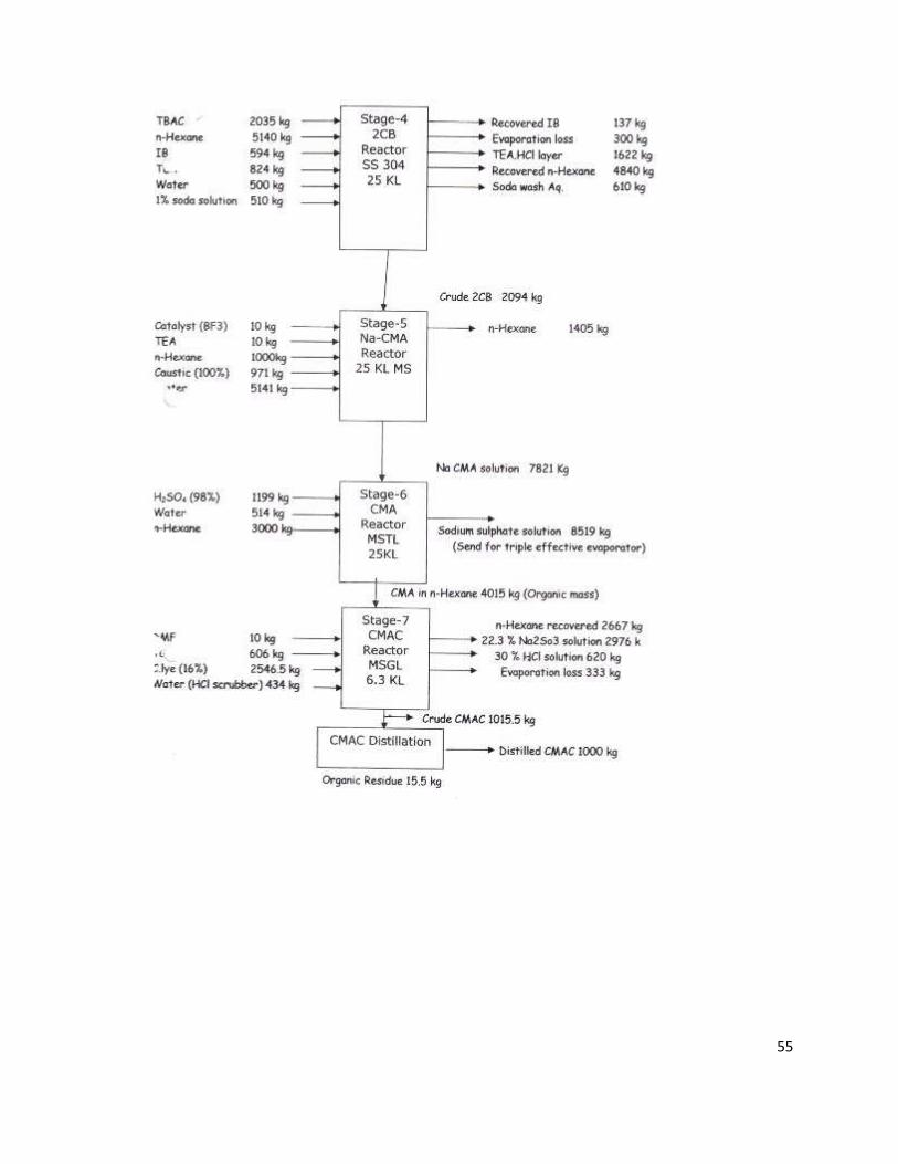
STAGE: 4 PREPARATION OF 2-CHLORO BUTANONE DERIVATIVE (2CB)
TBAC is reacted with isobutylene gas in presence of TEA (tri Ethyl Amine) at 70°C under 5.0 kg/cm2
pressures. n-Hexane is used as solvent. After reaction excess Isobutylene gas is recovered. The whole
mass is washed with water & Tri-ethylamine hydrochloric acid is separated & further preceded for TEA
recovery. The organic mass is neutralized with sodium bicarbonate & organic mass is transferred for
further process.
STAGE: 5 PREPARATION OF SODIUM SALT OF CYPERMETHRIN ACID (NA-CMA)
2CB is isomerised to 4CB in presence of Boron tri fluoride etherate solution (BF3) & TEA at 120°C. 4CB is
directly reacted with caustic solution gives Na-CMA. This intermediate is not getting isolated.
52
STAGE: 6 PREPARATION OF CYPERMETHRIN ACID (CMA)
Na-CMA is acidified with dilute Sulphuric acid at Room temperature. CMA is extracted in n-hexane.
Aqueous layer (sodium sulphate solution) is sent for triple effective evaporator. Organic
mass (n-hexane +CMA) is taken for next process.
STAGE: 7 PREPARATION OF CYPERMETHRIN ACID CHLORIDE (CMAC)
N-HEXANE IS RECOVERED FROM CMA SOLUTION. CRUDE CMA IS REACTED WITH THIONYL CHLORIDE
IN PRESENCE OF DMF CATALYST TO GIVE CRUDE CMAC. HCL & SO2 GAS GENERATED IS SCRUBBED IN
WATER & CAUSTIC SOLUTION RESPECTIVELY. CRUDE CMAC IS DISTILLED OUT UNDER HIGH VACUUM
TO GET PURE CMAC (CYPERMETHRIC ACID CHLORIDE). THE PURITY OF DISTILLED CMAC IS ABOVE 99%.
CHEMICAL REACTION
53
54
55

56
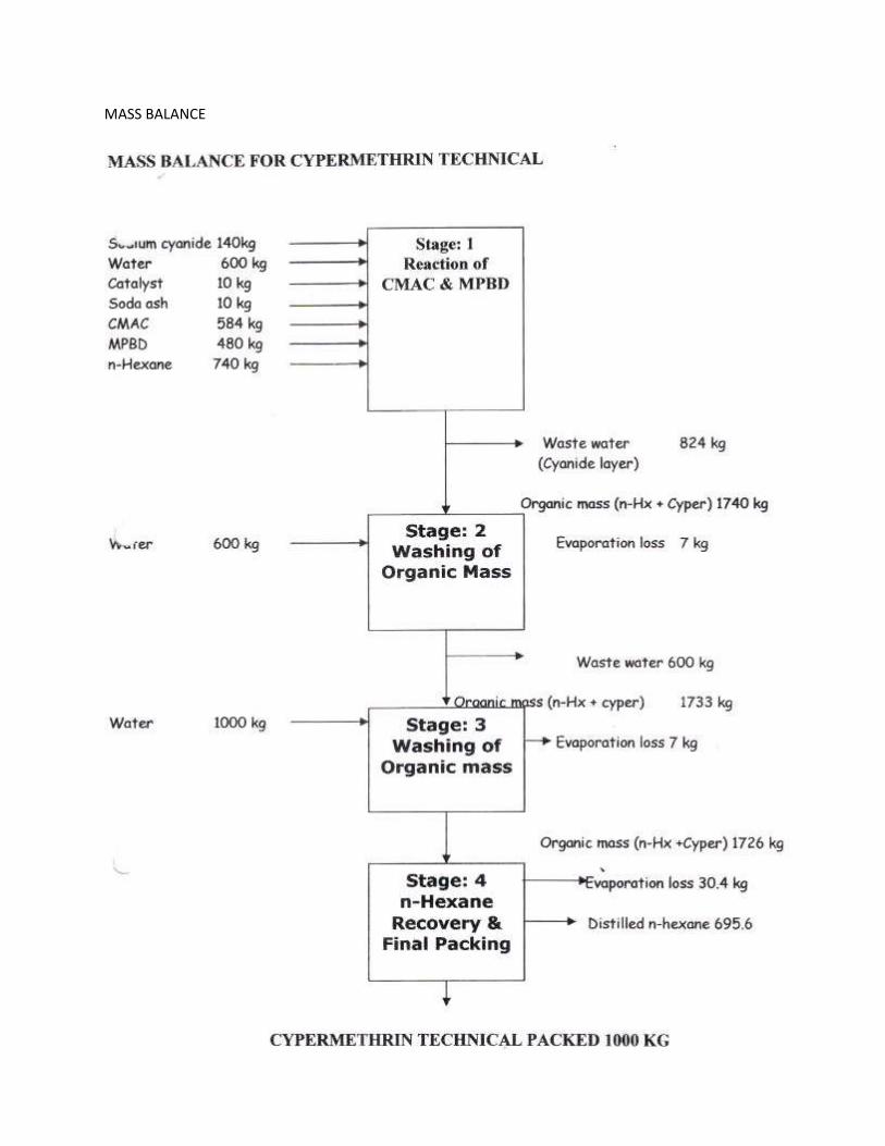
6) CYPERMETHRIN TECH.
MANUFACTURING PROCESS
Solution of CMAC (in-house manufactured as well as procured from the market) and Meta phenoxy
benzaldehyde reacts with solution of sodium cyanide in water in presence of phase transfer catalyst at
25 to 30°C to give Cypermethrin. After reaction water & cyanide layer is separated. The organic mass is
washed with water to remove traces of Cyanide. Water layer contain sodium cyanide and is treated with
sodium hypochlorite to destroy sodium cyanide the obtain purity of Cypermethrin is minimum 92%.
CHEMICAL REACTION
57
MASS BALANCE
58
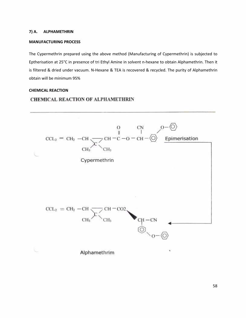
7) A. ALPHAMETHRIN
MANUFACTURING PROCESS
The Cypermethrin prepared using the above method (Manufacturing of Cypermethrin) is subjected to
Eptherisation at 25°C in presence of tri Ethyl Amine in solvent n-hexane to obtain Alphamethrin. Then it
is filtered & dried under vacuum. N-Hexane & TEA is recovered & recycled. The purity of Alphamethrin
obtain will be minimum 95%
CHEMICAL REACTION
59
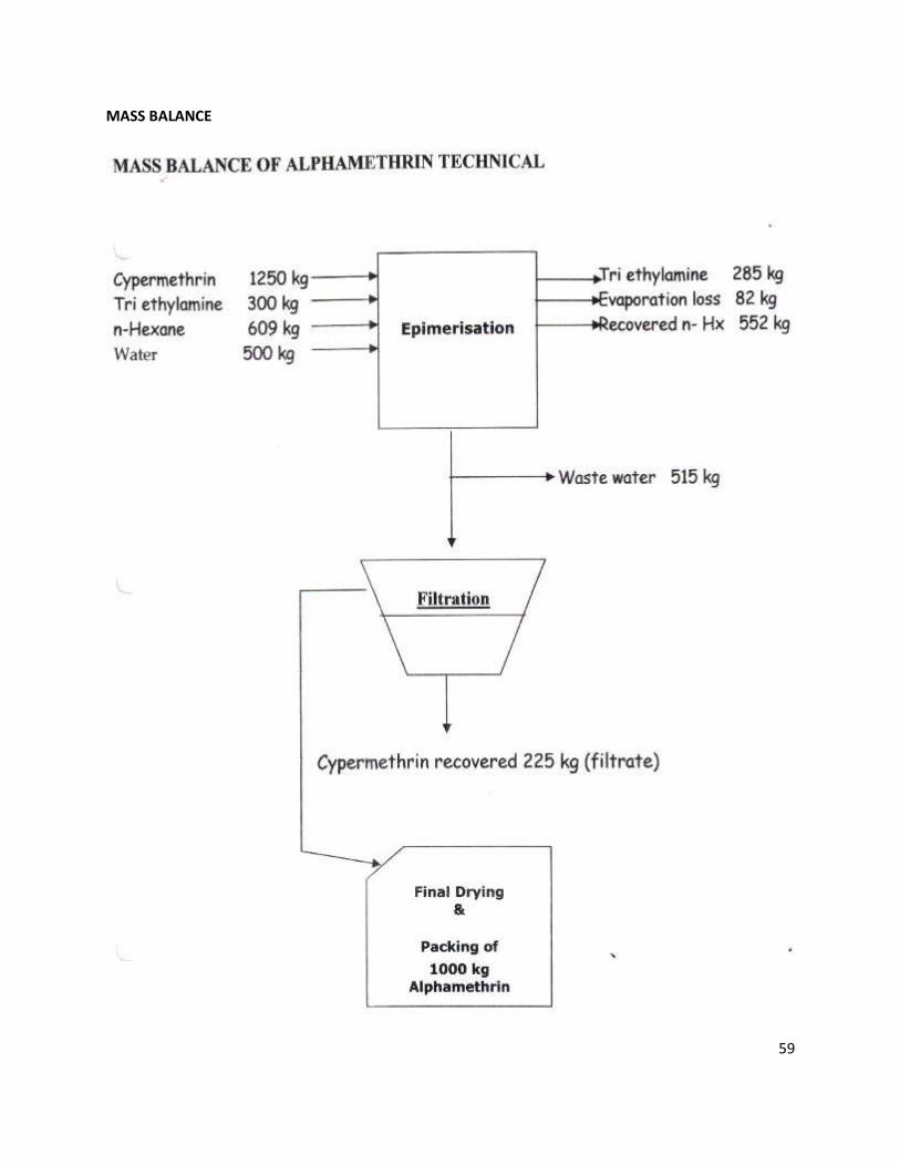
MASS BALANCE
60
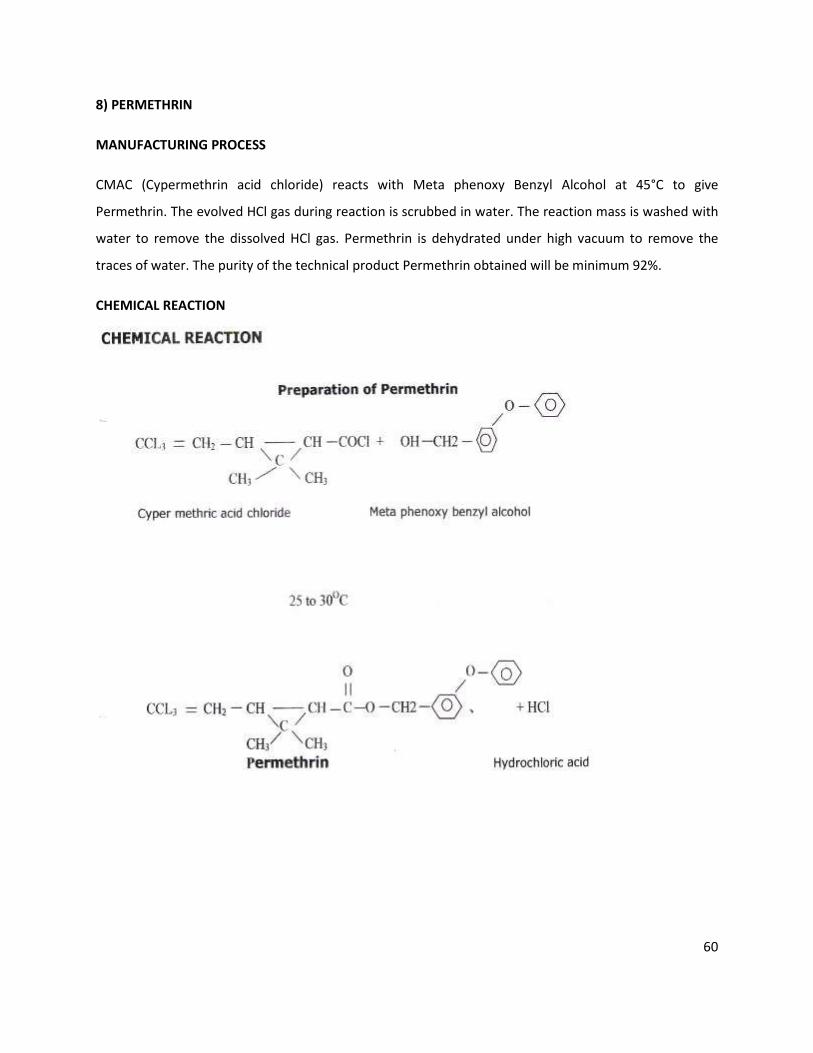
8) PERMETHRIN
MANUFACTURING PROCESS
CMAC (Cypermethrin acid chloride) reacts with Meta phenoxy Benzyl Alcohol at 45°C to give
Permethrin. The evolved HCl gas during reaction is scrubbed in water. The reaction mass is washed with
water to remove the dissolved HCl gas. Permethrin is dehydrated under high vacuum to remove the
traces of water. The purity of the technical product Permethrin obtained will be minimum 92%.
CHEMICAL REACTION
61
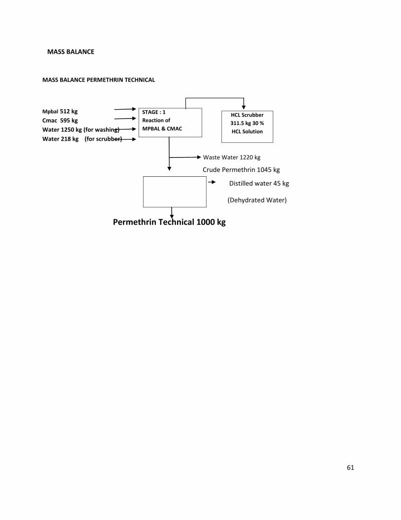
MASS BALANCE PERMETHRIN TECHNICAL
Mpbal 512 kg
Cmac 595 kg
Water 1250 kg (for washing)
Water 218 kg (for scrubber)
Waste Water 1220 kg
Permethrin Technical 1000 kg
STAGE : 1
Reaction of
MPBAL & CMAC
HCL Scrubber
311.5 kg 30 %
HCL Solution
Distilled water 45 kg
(Dehydrated Water)
Crude Permethrin 1045 kg
MASS BALANCE
62
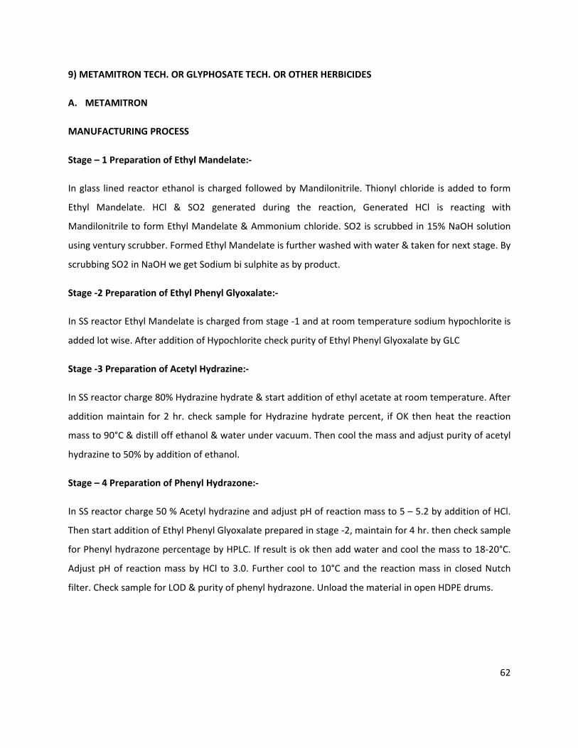
9) METAMITRON TECH. OR GLYPHOSATE TECH. OR OTHER HERBICIDES
A. METAMITRON
MANUFACTURING PROCESS
Stage – 1 Preparation of Ethyl Mandelate:-
In glass lined reactor ethanol is charged followed by Mandilonitrile. Thionyl chloride is added to form
Ethyl Mandelate. HCl & SO2 generated during the reaction, Generated HCl is reacting with
Mandilonitrile to form Ethyl Mandelate & Ammonium chloride. SO2 is scrubbed in 15% NaOH solution
using ventury scrubber. Formed Ethyl Mandelate is further washed with water & taken for next stage. By
scrubbing SO2 in NaOH we get Sodium bi sulphite as by product.
Stage -2 Preparation of Ethyl Phenyl Glyoxalate:-
In SS reactor Ethyl Mandelate is charged from stage -1 and at room temperature sodium hypochlorite is
added lot wise. After addition of Hypochlorite check purity of Ethyl Phenyl Glyoxalate by GLC
Stage -3 Preparation of Acetyl Hydrazine:-
In SS reactor charge 80% Hydrazine hydrate & start addition of ethyl acetate at room temperature. After
addition maintain for 2 hr. check sample for Hydrazine hydrate percent, if OK then heat the reaction
mass to 90°C & distill off ethanol & water under vacuum. Then cool the mass and adjust purity of acetyl
hydrazine to 50% by addition of ethanol.
Stage – 4 Preparation of Phenyl Hydrazone:-
In SS reactor charge 50 % Acetyl hydrazine and adjust pH of reaction mass to 5 – 5.2 by addition of HCl.
Then start addition of Ethyl Phenyl Glyoxalate prepared in stage -2, maintain for 4 hr. then check sample
for Phenyl hydrazone percentage by HPLC. If result is ok then add water and cool the mass to 18-20°C.
Adjust pH of reaction mass by HCl to 3.0. Further cool to 10°C and the reaction mass in closed Nutch
filter. Check sample for LOD & purity of phenyl hydrazone. Unload the material in open HDPE drums.
63
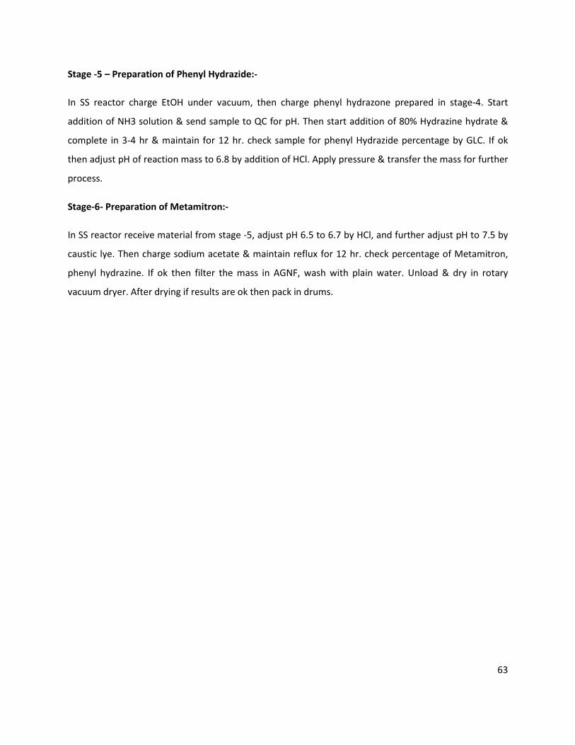
Stage -5 – Preparation of Phenyl Hydrazide:-
In SS reactor charge EtOH under vacuum, then charge phenyl hydrazone prepared in stage-4. Start
addition of NH3 solution & send sample to QC for pH. Then start addition of 80% Hydrazine hydrate &
complete in 3-4 hr & maintain for 12 hr. check sample for phenyl Hydrazide percentage by GLC. If ok
then adjust pH of reaction mass to 6.8 by addition of HCl. Apply pressure & transfer the mass for further
process.
Stage-6- Preparation of Metamitron:-
In SS reactor receive material from stage -5, adjust pH 6.5 to 6.7 by HCl, and further adjust pH to 7.5 by
caustic lye. Then charge sodium acetate & maintain reflux for 12 hr. check percentage of Metamitron,
phenyl hydrazine. If ok then filter the mass in AGNF, wash with plain water. Unload & dry in rotary
vacuum dryer. After drying if results are ok then pack in drums.
64
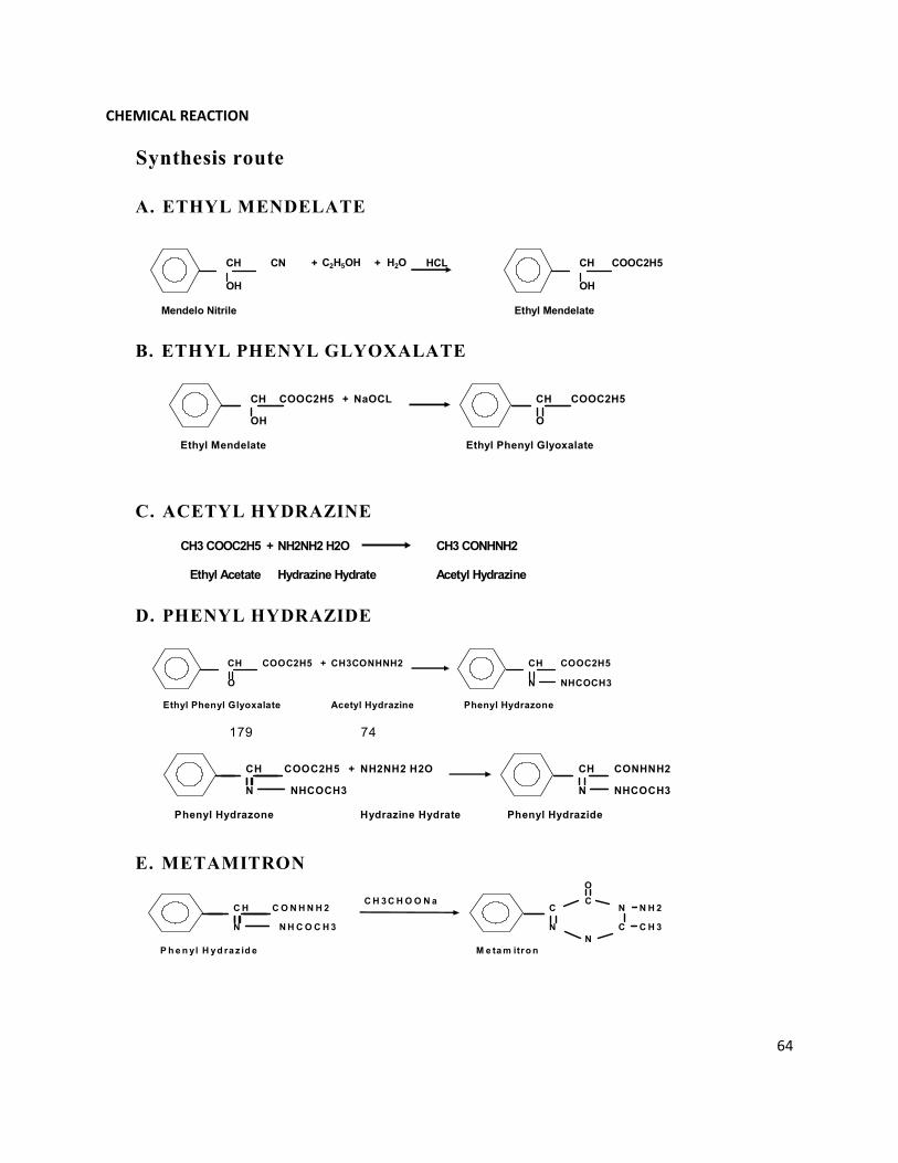
Synthesis route
A. ETHYL MENDELATE
B. ETHYL PHENYL GLYOXALATE
C. ACETYL HYDRAZINE
D. PHENYL HYDRAZIDE
179 74
E. METAMITRON
CH CN + C2H5OH + H2O HCL CH COOC2H5
OH OH
Mendelo Nitrile Ethyl Mendelate
CH COOC2H5 + NaOCL CH COOC2H5
OH O
Ethyl Mendelate Ethyl Phenyl Glyoxalate
CH3 COOC2H5 + NH2NH2 H2O CH3 CONHNH2
Ethyl Acetate Hydrazine Hydrate Acetyl Hydrazine
CH COOC2H5 + CH3CONHNH2 CH COOC2H5
O N NHCOCH3
Ethyl Phenyl Glyoxalate Acetyl Hydrazine Phenyl Hydrazone
CH COOC2H5 + NH2NH2 H2O CH CONHNH2
N NHCOCH3 N NHCOCH3
Phenyl Hydrazone Hydrazine Hydrate Phenyl Hydrazide
O
C H C O N H N H 2 C H 3 C H O O N a
CC
N N H 2
N N H C O C H 3 N C C H 3
N
P h e n yl H yd ra z id e M e ta m itro n
CHEMICAL REACTION

65
Stage: Ethyl Mendalate from Mendelonitrile
IS [R+F] 1669 510 SO2 Gas
Water 63
Mendelonitrile 1377
TC 951
3550 Reaction Mass
510 NH4Cl
Water-1 939 2411 Water Wash -1
Water-2 209 215 Water Wash -2
Toluene 1184
2746 EM in Toluene
Stage: Ethyl Mendalate from Mendelonitrile
Water 209 250 C S Lye Wash
C S Lye 31 10253 Hypo Treated Layers
TEBA 57
NaOCl 10015
2555 EPG in Toluene
NaHSO3 21 237 Aqueous Layer
Water 209
2548 Washed EPG in Toluene
55 kgs. Loss
990 Toluene Recovered
1503 Crude EPG
for distillation
22 1st Cut
1420 Main Cut-Taken for Meta
Preparation
61 Residual for Incineration
Toluene Recovery
EPG Distillation
Ethyl Mendelate Preparation
Ethyl Mendelate Washing
Ethyl Phenyl Glyoxalate
Preparation
Sodium Bisulfite Washing
MASS BALANCE
66
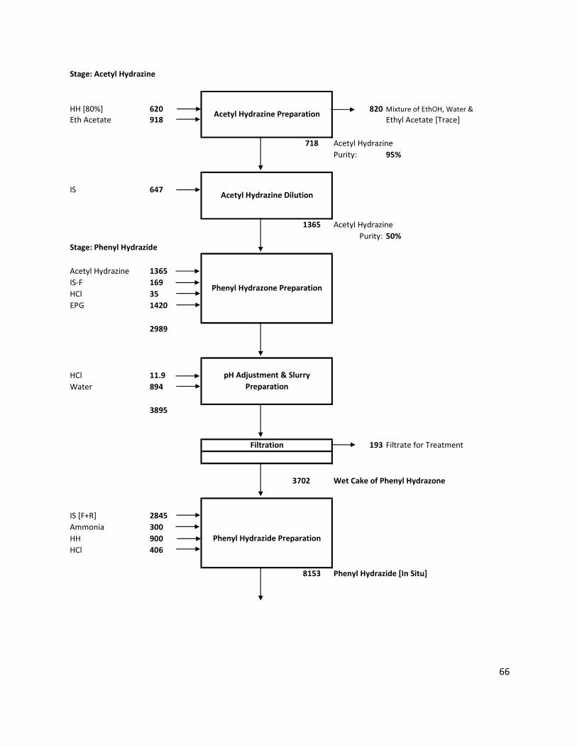
Stage: Acetyl Hydrazine
HH [80%] 620 820 Mixture of EthOH, Water &
Eth Acetate 918 Ethyl Acetate [Trace]
718 Acetyl Hydrazine
Purity: 95%
IS 647
1365 Acetyl Hydrazine
Purity: 50%
Stage: Phenyl Hydrazide
Acetyl Hydrazine 1365
IS-F 169
HCl 35
EPG 1420
2989
HCl 11.9
Water 894
3895
193 Filtrate for Treatment
3702 Wet Cake of Phenyl Hydrazone
IS [F+R] 2845
Ammonia 300
HH 900
HCl 406
8153 Phenyl Hydrazide [In Situ]
Acetyl Hydrazine Preparation
Acetyl Hydrazine Dilution
Phenyl Hydrazone Preparation
pH Adjustment & Slurry
Preparation
Filtration
Phenyl Hydrazide Preparation
67
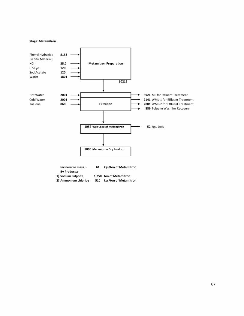
Stage: Metamitron
Phenyl Hydrazide 8153
[In Situ Material]
HCl 25.0
C S Lye 120
Sod Acetate 120
Water 1801
10219
Hot Water 2001 8921 ML for Effluent Treatment
Cold Water 2001 2141 WML-1 for Effluent Treatment
Toluene 860 2081 WML-2 for Effluent Treatment
886 Toluene Wash for Recovery
1052 Wet Cake of Metamitron 52 kgs. Loss
1000 Metamitron Dry Product
Incinerable mass :- 61 kgs/ton of Metamitron
By Products:-
1) Sodium Sulphite 1.250 ton of Metamitron
2) Ammonium chloride 510 kgs/ton of Metamitron
Metamitron Preparation
Filtration
68
B. GLYPHOSATE ACID TECHNICAL
MANUFACTURING PROCESS
Take water, DEA, 48% caustic lye and catalyst in a pressure rector. Maintain the reaction temperature
160°C and pressure 10 kg /cm2. DSIDA (Disodium Salt of imino diacetic acid) formation taken place with
total conversion of 90% hydrogen gas is vented to atmosphere through scrubber during the reaction.
Catalyst in filtered at 70°C and recycled in next batch as such. Neutralize the mother liquor to pH 6.7
and, add PCl3 at 30°C and reflux at 100°C. Add formaldehyde at 100-110°C. After completion of reaction,
cool the mass to 30°C and centrifuge the crystals Phosphoro methyl imino diacetic acid (PMIDA) Mother
liquor is separately taken for the neutralization and evaporation. The cake is washed with water. Wet
PMIDA is reacted with oxygen to produce Glyphosate acid (final product). It is dried with hot air and
product is packed in bags.
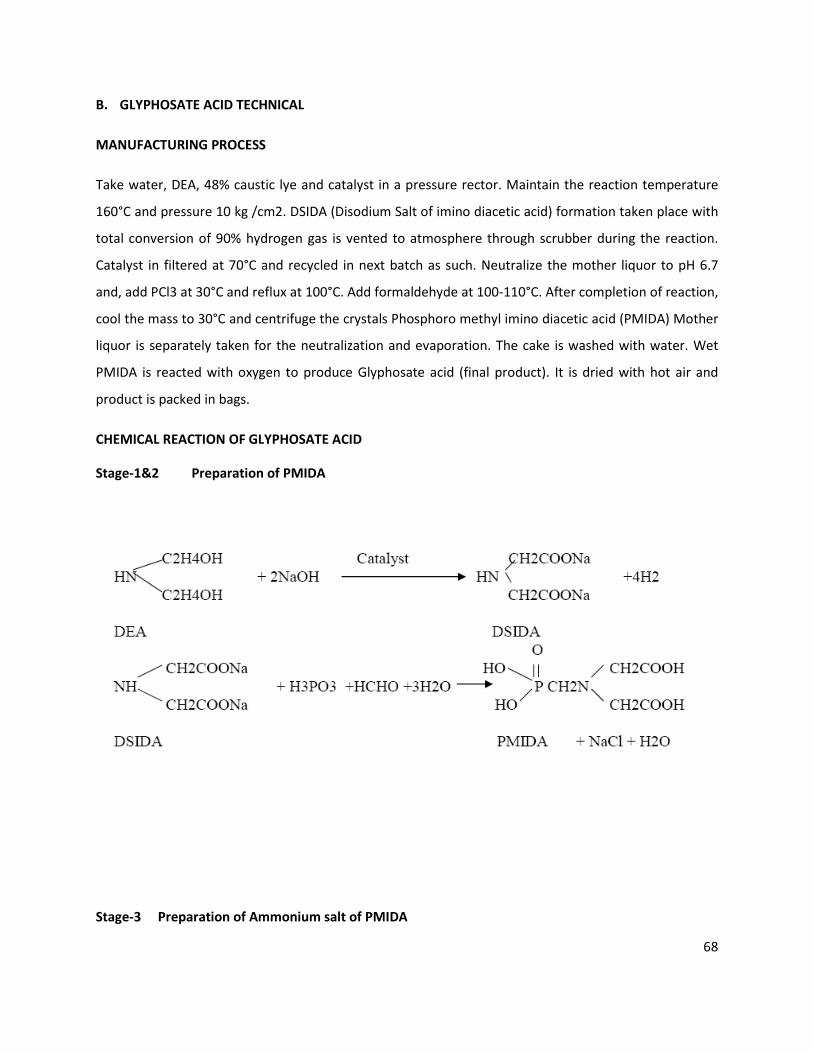
CHEMICAL REACTION OF GLYPHOSATE ACID
Stage-1&2 Preparation of PMIDA
Stage-3 Preparation of Ammonium salt of PMIDA
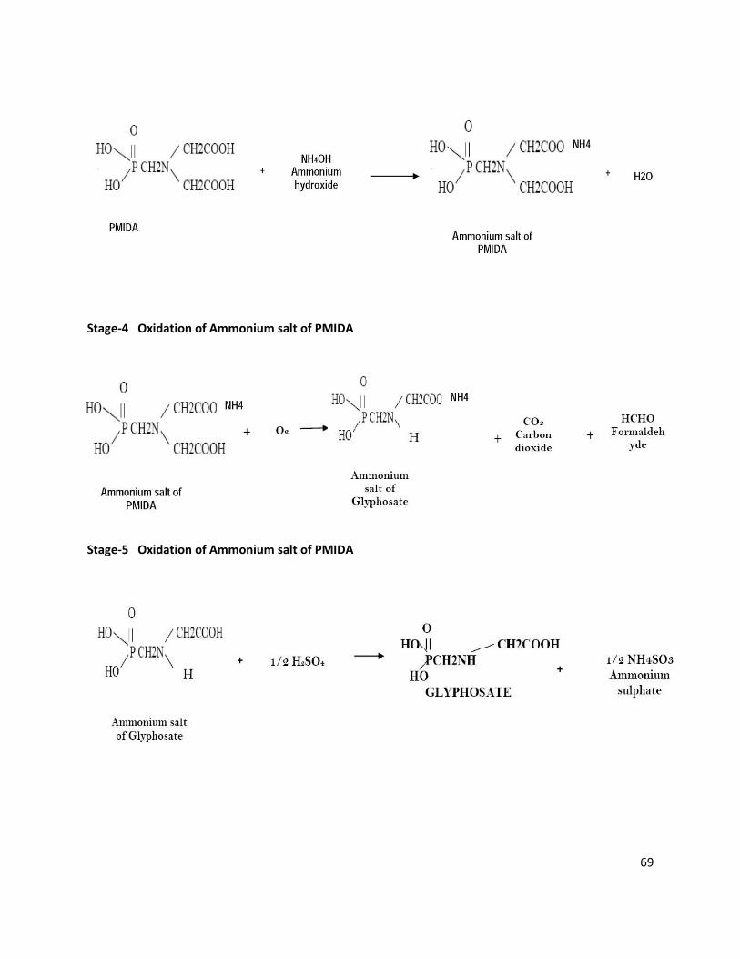
69
Stage-4 Oxidation of Ammonium salt of PMIDA
Stage-5 Oxidation of Ammonium salt of PMIDA
70
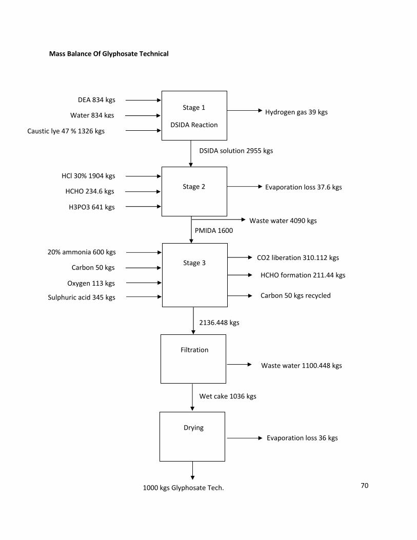
Mass Balance Of Glyphosate Technical
Evaporation loss 37.6 kgs
HCHO formation 211.44 kgs
Carbon 50 kgs recycled
DEA 834 kgs
Caustic lye 47 % 1326 kgs
Hydrogen gas 39 kgs Water 834 kgs Stage 1
DSIDA Reaction
HCl 30% 1904 kgs
H3PO3 641 kgs
HCHO 234.6 kgs Stage 2
DSIDA solution 2955 kgs
20% ammonia 600 kgs
Oxygen 113 kgs
CO2 liberation 310.112 kgs
Carbon 50 kgs Stage 3
Waste water 4090 kgs
Sulphuric acid 345 kgs
PMIDA 1600
Filtration
Waste water 1100.448 kgs
Wet cake 1036 kgs
Drying
1000 kgs Glyphosate Tech.
Evaporation loss 36 kgs
2136.448 kgs
71
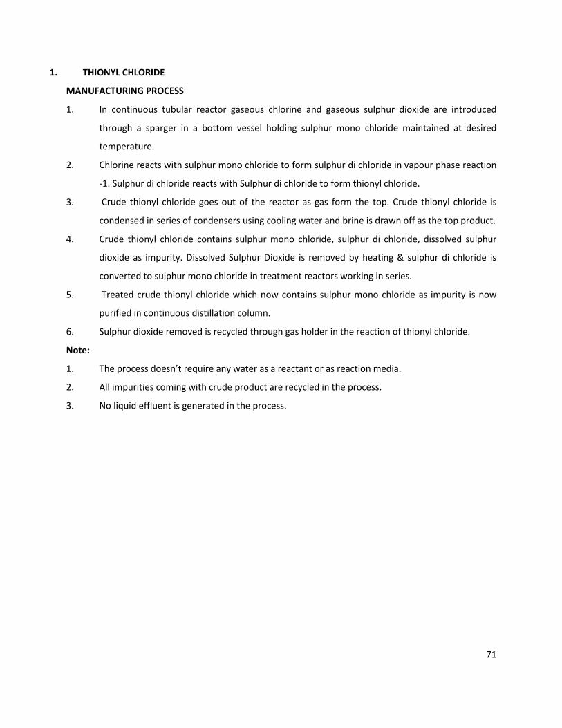
1. THIONYL CHLORIDE
MANUFACTURING PROCESS
1. In continuous tubular reactor gaseous chlorine and gaseous sulphur dioxide are introduced
through a sparger in a bottom vessel holding sulphur mono chloride maintained at desired
temperature.
2. Chlorine reacts with sulphur mono chloride to form sulphur di chloride in vapour phase reaction
-1. Sulphur di chloride reacts with Sulphur di chloride to form thionyl chloride.
3. Crude thionyl chloride goes out of the reactor as gas form the top. Crude thionyl chloride is
condensed in series of condensers using cooling water and brine is drawn off as the top product.
4. Crude thionyl chloride contains sulphur mono chloride, sulphur di chloride, dissolved sulphur
dioxide as impurity. Dissolved Sulphur Dioxide is removed by heating & sulphur di chloride is
converted to sulphur mono chloride in treatment reactors working in series.
5. Treated crude thionyl chloride which now contains sulphur mono chloride as impurity is now
purified in continuous distillation column.
6. Sulphur dioxide removed is recycled through gas holder in the reaction of thionyl chloride.
Note:
1. The process doesn’t require any water as a reactant or as reaction media.
2. All impurities coming with crude product are recycled in the process.
3. No liquid effluent is generated in the process.
72
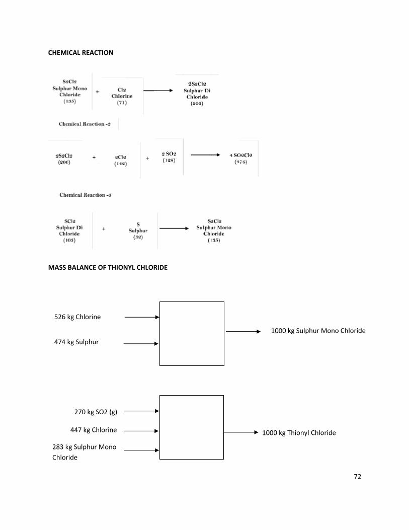
CHEMICAL REACTION
MASS BALANCE OF THIONYL CHLORIDE
270 kg SO2 (g)
283 kg Sulphur Mono
Chloride
1000 kg Thionyl Chloride 447 kg Chlorine
526 kg Chlorine
474 kg Sulphur
1000 kg Sulphur Mono Chloride
73
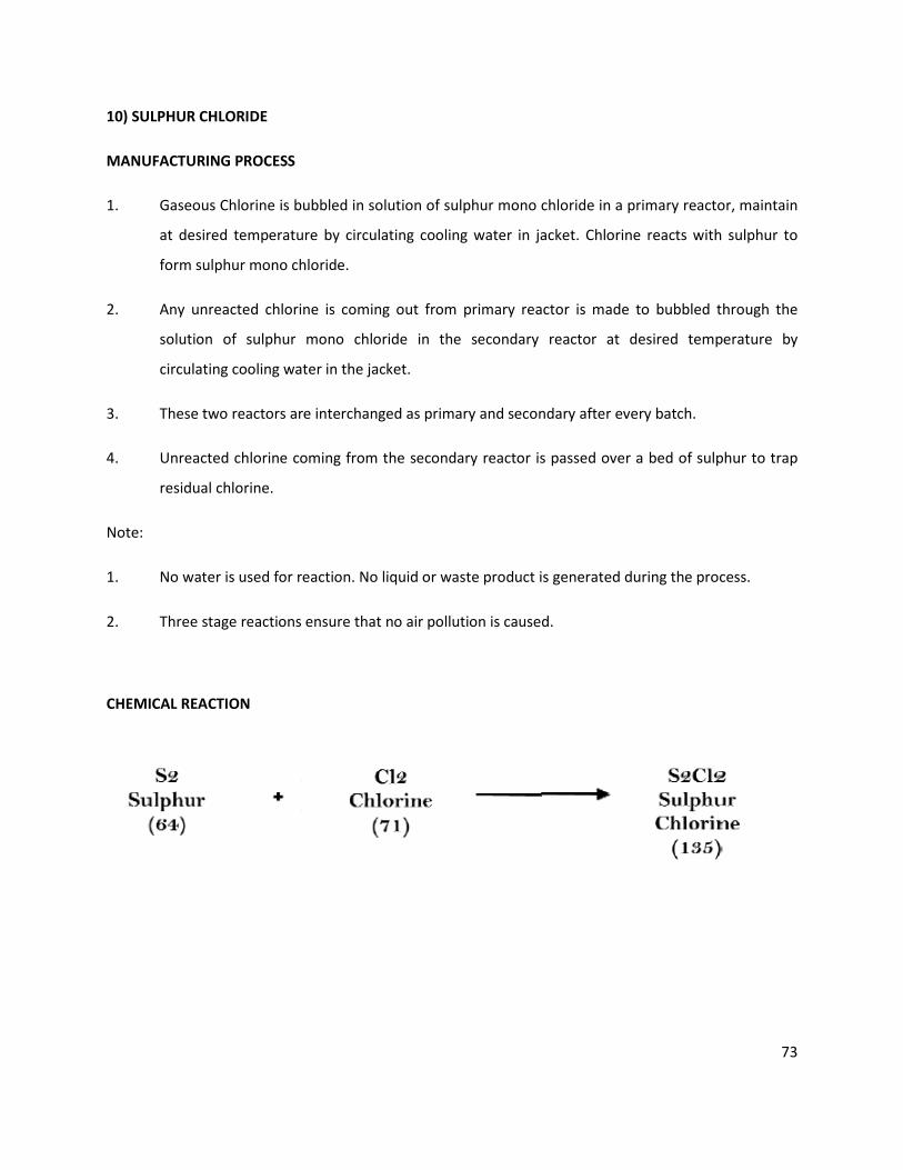
10) SULPHUR CHLORIDE
MANUFACTURING PROCESS
1. Gaseous Chlorine is bubbled in solution of sulphur mono chloride in a primary reactor, maintain
at desired temperature by circulating cooling water in jacket. Chlorine reacts with sulphur to
form sulphur mono chloride.
2. Any unreacted chlorine is coming out from primary reactor is made to bubbled through the
solution of sulphur mono chloride in the secondary reactor at desired temperature by
circulating cooling water in the jacket.
3. These two reactors are interchanged as primary and secondary after every batch.
4. Unreacted chlorine coming from the secondary reactor is passed over a bed of sulphur to trap
residual chlorine.
Note:
1. No water is used for reaction. No liquid or waste product is generated during the process.
2. Three stage reactions ensure that no air pollution is caused.
CHEMICAL REACTION
74
11) ACID CHLORIDE LIKE VALEORYL CHLORIDE, PHENYL ACETYL CHLORIDE
VALEORYL CHLORIDE
MANUFACTURING PROCESS & CHEMICAL REACTION
Valeroyl Chloride is produced by the reaction of Valeoric Acid and Thionyl Chloride in as MS GL Reactor
and the reaction takes place as follows.
CH3 (CH2)3 COOH + SOCl2 = CH3 (CH2)3 COCl + SO2 + HCl
102 + 119 = 120.5 + 64 + 36.5
221 = 221
Valeroric Acid is charged in to the MSGL Reactor and heating is started. After the required temperature,
Thionyl Chloride is added slowly in the reactor generated Hydrochloric Acid gas is absorbed in the water
to Produced Hydrochloric Acids and Sulphur Dioxide is absorbed in Soda Ash Solution to produced
Sodium Bi Sulphite. After complete the reaction bottom material is transferred in to Distillation Column
where pure Valeoryl Chloride product is obtained.
MASS BALANCE
Per 1000 Kgs of Valeoryl Chloride:
Thionyl Chloride: 990 Kgs,
Valeoric Acid : 850 Kgs.
By Product: HCl Gas to Scrubber 302 Kgs,
By Product: SO2 Gas to Scrubber 510 Kgs,
Crude Valeoryl Chloride: 1028 Kgs,
Distillation:
Valeroyl Chloride: 1000 Kgs.
Distillation loss: 20 Kgs.
Residue : 8 Kgs.
Qty.of RM/Month:
Thionyl Chloride: 100 MT
Valeoric Acid : 85 MT
75
PHENYL ACETYL CHLORIDE
MANUFACTURING PROCESS & CHEMICAL REACTION
Valeroyl Chloride is produced by the reaction of Valeoric Acid and Thionyl Chloride in as MS GL Reactor
and the reaction takes place as follows.
C6H5CH2COOH + SOCl2 = C6H5CH2COCl + SO2 + HCl
136 + 119 = 154.5 + 64 + 36.5
255 = 255
Phenyl Acetic Acid is charged in to the MSGL Reactor and heating is started. After the required
temperature, Thionyl Chloride is added slowly in the reactor generated Hydrochloric Acid gas is
absorbed in the water to Produced Hydrochloric Acids and Sulphur Dioxide is absorbed in Soda Ash
Solution to produced Sodium Bi Sulphite. After complete the reaction bottom material is transferred in
to Distillation Column where pure Phenyl Acetyl Chloride product is obtained.
MASS BALANCE
Per 1000 Kgs of Phenyl Chloride:
Thionyl Chloride: 970 Kgs,
Valeoric Acid : 856 Kgs.
By Product: HCl Gas to Scrubber 336 Kgs,
By Product: SO2 Gas to Scrubber 462 Kgs,
Crude Valeoryl Chloride: 1028 Kgs,
Distillation:
Valeroyl Chloride: 1000 Kgs.
Distillation loss: 20 Kgs.
Residue : 8 Kgs.
Qty.of RM/Month:
Thionyl Chloride: 97 MT
VALEORIC ACID : 86 MT
76
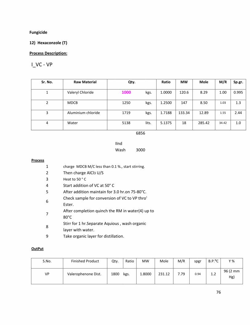
Fungicide
12) Hexaconzole (T)
Process Description:
I_VC - VP
Sr. No. Raw Material Qty. Ratio MW Mole M/R Sp.gr.
1 Valeryl Chloride 1000 kgs. 1.0000 120.6 8.29 1.00 0.995
2 MDCB 1250 kgs. 1.2500 147 8.50 1.03 1.3
3 Aluminium chloride 1719 kgs. 1.7188 133.34 12.89 1.55 2.44
4 Water 5138 lits. 5.1375 18 285.42 34.42 1.0
6856
IInd
Wash 3000
Process
1 charge MDCB M/C less than 0.1 %., start stirring.
2 Then charge AlCl3 U/S
3 Heat to 50 ° C
4 Start addition of VC at 50° C
5 After addition maintain for 3.0 hr.on 75-80°C.
6
Check sample for conversion of VC to VP thro'
Ester.
7
After completion quinch the RM in water(4) up to
80°C
8
Stirr for 1 hr.Separate Aquious , wash organic
layer with water.
9 Take organic layer for distillation.
OutPut
S.No. Finished Product Qty. Ratio MW Mole M/R spgr B.P.⁰C Y %
VP Valerophenone Dist. 1800 kgs. 1.8000 231.12 7.79 0.94 1.2 96 (2 mm
Hg)
77
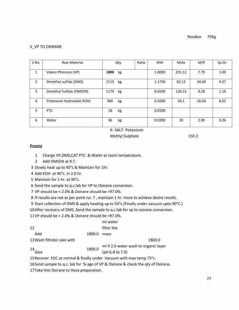
Residue 70Kg
II_VP TO OXIRANE
S.No. Raw Material Qty. Ratio MW Mole M/R Sp.Gr.
1 Valero Phenone (VP) 1800 kg. 1.0000 231.12 7.79 1.00
2 Dimethyl sulfide (DMS) 2115 kg. 1.1750 62.13 34.04 4.37
3 Dimethyl Sulfate (DMSO4) 1170 kg. 0.6500 126.13 9.28 1.19
4 Potassium Hydroxide( KOH) 900 kg. 0.5000 56.1 16.04 8.02
5 PTC 18 kg. 0.0100
6 Water 36 kg. 0.0200 18 2.00 0.26
K- SALT- Potassium
Methyl Sulphate
150.2
Process
1 Charge VP,DMS,CAT PTC & Water at room temperature.
2 Add DMSO4 at R.T.
3 Slowly heat up to 40°c & Maintain for 1hr.
4 Add KOH at 40°c. in 2.0 hr.
5 Maintain for 1 hr. at 40°c.
6 Send the sample to q.c.lab for VP to Oxirane conversion.
7 VP should be < 2.0% & Oxirane should be >97.0%.
8 If results are not as per point no. 7 , maintain 1 hr. more to achieve desire results.
9 Start collection of DMS & apply heating up to 50°c.(Finally under vacuum upto 90°C.)
10 After recovery of DMS ,Send the sample to q.c.lab for vp to oxirane conversion.
11 VP should be < 2.0% & Oxirane should be >97.0%.
12
Add 1800.0
ml water
filter the
mass
13 Wash filtrate cake with 1800.0
14 Give
1800.0 ml X 2.0 water wash to organic layer
(pH 6.8 to 7.0)
15 Recover EDC at normal & finally under Vacuum with max temp 75°c.
16 Send sample to q.c. lab for % age of VP & Oxirane & check the qty of Oxirane.
17 Take this Oxirane to Hexa preparation.
78
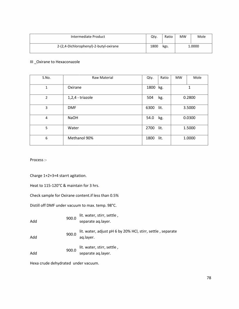
Intermediate Product Qty. Ratio MW Mole
2-(2,4-Dichlorophenyl)-2-butyl-oxirane 1800 kgs. 1.0000
III _Oxirane to Hexaconazole
S.No. Raw Material Qty. Ratio MW Mole
1 Oxirane 1800 kg. 1
2 1,2,4 - triazole 504 kg. 0.2800
3 DMF 6300 lit. 3.5000
4 NaOH 54.0 kg. 0.0300
5 Water 2700 lit. 1.5000
6 Methanol 90% 1800 lit. 1.0000
Process :-
Charge 1+2+3+4 starrt agitation.
Heat to 115-120°C & maintain for 3 hrs.
Check sample for Oxirane content.if less than 0.5%
Distill off DMF under vacuum to max. temp. 98°C.
Add 900.0
lit. water, stirr, settle ,
separate aq.layer.
Add 900.0
lit. water, adjust pH 6 by 20% HCl, stirr, settle , separate
aq.layer.
Add 900.0
lit. water, stirr, settle ,
separate aq.layer.
Hexa crude dehydrated under vacuum.
79
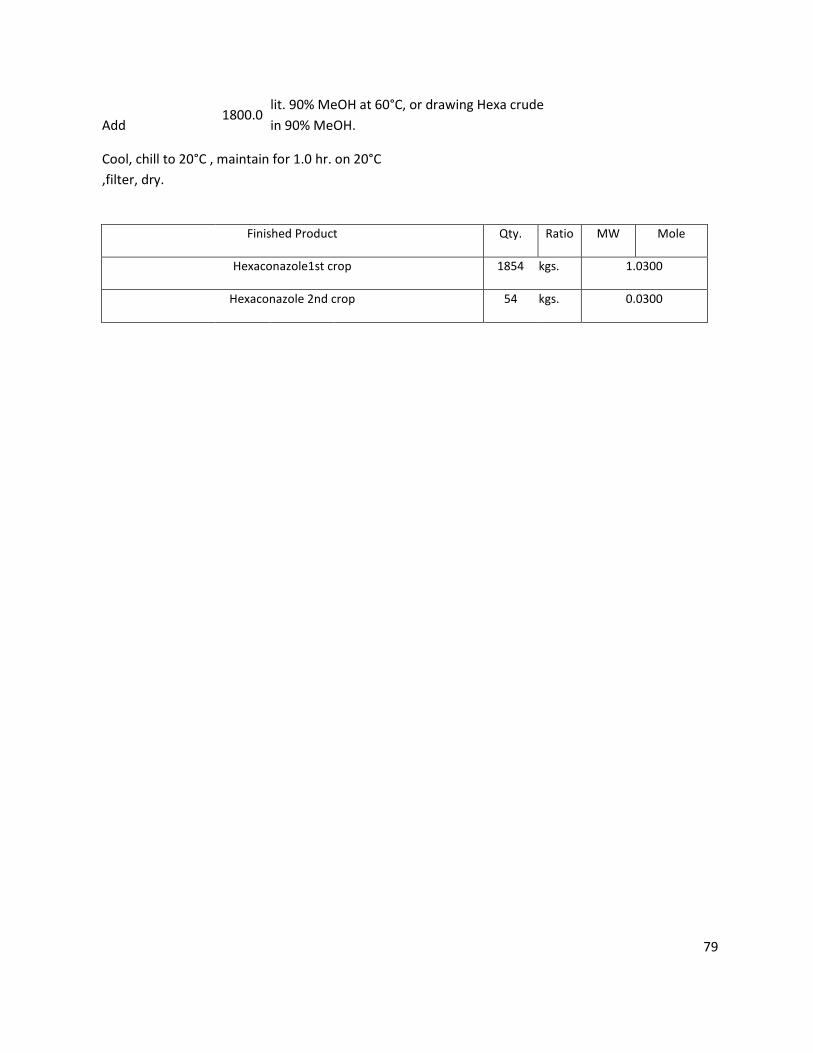
Add 1800.0
lit. 90% MeOH at 60°C, or drawing Hexa crude
in 90% MeOH.
Cool, chill to 20°C , maintain for 1.0 hr. on 20°C
,filter, dry.
Finished Product Qty. Ratio MW Mole
Hexaconazole1st crop 1854 kgs. 1.0300
Hexaconazole 2nd crop 54 kgs. 0.0300
80
Chemical Reaction
HEXACONZOLE REACTION SCHEME
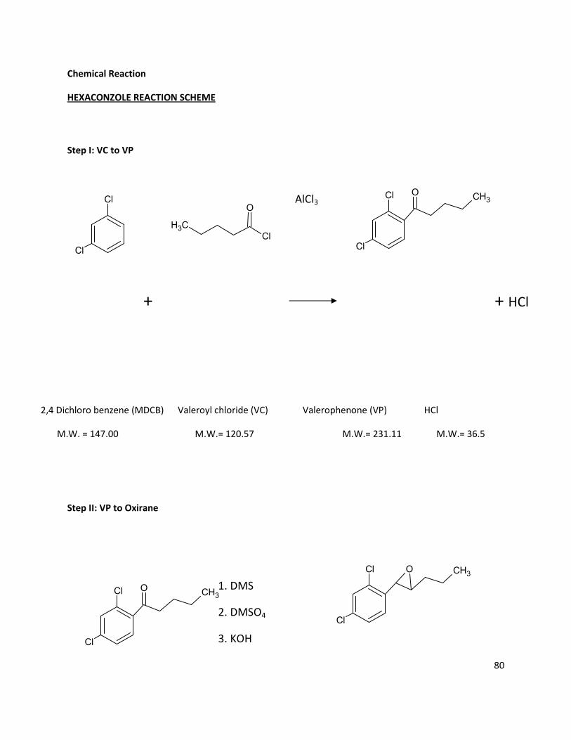
Step I: VC to VP
AlCl3
+ + HCl
2,4 Dichloro benzene (MDCB) Valeroyl chloride (VC) Valerophenone (VP) HCl
M.W. = 147.00 M.W.= 120.57 M.W.= 231.11 M.W.= 36.5
Step II: VP to Oxirane
1. DMS
2. DMSO4
3. KOH
Cl
Cl
CH3Cl
O
Cl
Cl
CH3O
Cl
Cl
CH3O
Cl
Cl
CH3O
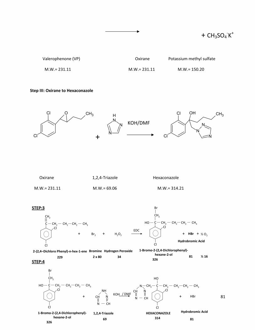
81
+ CH3SO4-K
+
Valerophenone (VP) Oxirane Potassium methyl sulfate
M.W.= 231.11 M.W.= 231.11 M.W.= 150.20
Step III: Oxirane to Hexaconazole
KOH/DMF
+
Oxirane 1,2,4-Triazole Hexaconazole
M.W.= 231.11 M.W.= 69.06 M.W.= 314.21
+ +
+ + HBr
81
STEP:3
STEP:4
Cl
1-Bromo-2-(2,4-Dichlorophenyl)-
hexane-2-ol
326
Cl
HBr
81
1,2,4-Triazole
69
CH
N
N
CH
NHKOH
HEXACONAZOLE
314
Bromine
2 x 80
Br2
2-(2,4–Dichloro Phenyl)-n-hex-1-ene
229
Cl
Cl
CH2 CH2 CH2 CH3C
CH2
+
Hydrogen Peroxide
34
H2O2
CH2 CH2 CH2 CH3C
CH2
HO
Br
½ O2+
½ 16
Cl
1-Bromo-2-(2,4-Dichlorophenyl)-
hexane-2-ol
326
Cl
CH2 CH2 CH2 CH3C
CH2
HO
Br
EDC
DMFCl
Cl
CH2 CH2 CH2 CH3CCH2
HO
CH
N
N
CH
N
/
Hydrobromic Acid
Hydrobromic Acid
Cl
Cl
CH3O
NH
N
N
Cl
Cl
OH CH3
N
N
N
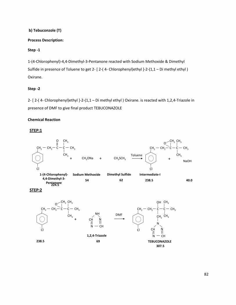
82
b) Tebuconzole (T)
Process Description:
Step -1
1-(4-Chlorophenyl)-4,4-Dimethyl-3-Pentanone reacted with Sodium Methoxide & Dimethyl
Sulfide in presence of Toluene to get 2- [ 2-( 4- Chlorophenyl)ethyl ]-2-(1,1 – Di methyl ethyl )
Oxirane.
Step -2
2- [ 2-( 4- Chlorophenyl)ethyl ]-2-(1,1 – Di methyl ethyl ) Oxirane. is reacted with 1,2,4-Triazole in
presence of DMF to give final product TEBUCONAZOLE
Chemical Reaction
Cl
1-(4-Chlorophenyl)-
4,4-Dimethyl-3-
Pentanone224.5
+
Sodium Methoxide
54
+NaOH
40.0
STEP:1
Toluene
Intermediate-I
238.5
+
STEP:2
DMF
CH2 CH2 C CH3C
O CH3
CH3CH3ONa + CH3SCH3
Dimethyl Sulfide
62
Cl
CH2 CH2 C CH3C
OCH3
CH3
CH2
238.5
Cl
CH2 CH2 C CH3C
OCH3
CH3
CH2
1,2,4-Triazole
69
CH
N
N
CH
NH
Cl
CH2 CH2 C CH3C
OH CH3
CH3CH2
CH
N
N
CH
N
TEBUCONAZOLE
307.5
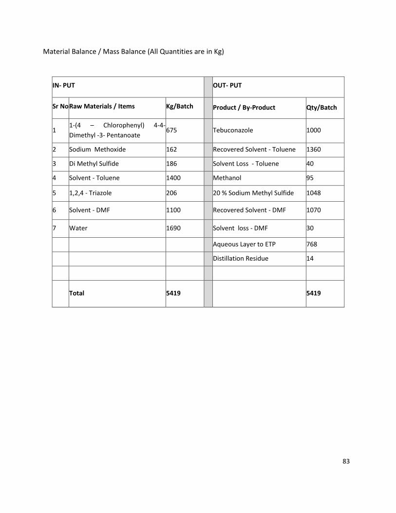
83
Material Balance / Mass Balance (All Quantities are in Kg)
IN- PUT OUT- PUT
Sr No Raw Materials / Items Kg/Batch Product / By-Product Qty/Batch
1 1-(4 – Chlorophenyl) 4-4-
Dimethyl -3- Pentanoate 675 Tebuconazole 1000
2 Sodium Methoxide 162 Recovered Solvent - Toluene 1360
3 Di Methyl Sulfide 186 Solvent Loss - Toluene 40
4 Solvent - Toluene 1400 Methanol 95
5 1,2,4 - Triazole 206 20 % Sodium Methyl Sulfide 1048
6 Solvent - DMF 1100 Recovered Solvent - DMF 1070
7 Water 1690 Solvent loss - DMF 30
Aqueous Layer to ETP 768
Distillation Residue 14
Total 5419 5419
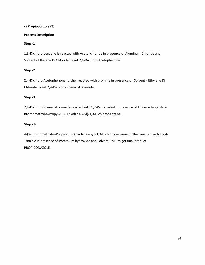
84
c) Propioconzole (T)
Process Description
Step -1
1,3-Dichloro benzene is reacted with Acetyl chloride in presence of Aluminum Chloride and
Solvent - Ethylene Di Chloride to get 2,4-Dichloro Acetophenone.
Step -2
2,4-Dichloro Acetophenone further reacted with bromine in presence of Solvent - Ethylene Di
Chloride to get 2,4-Dichloro Phenacyl Bromide.
Step -3
2,4-Dichloro Phenacyl bromide reacted with 1,2-Pentanediol in presence of Toluene to get 4-(2-
Bromomethyl-4-Propyl-1,3-Dioxolane-2-yl)-1,3-Dichlorobenzene.
Step - 4
4-(2-Bromomethyl-4-Propyl-1,3-Dioxolane-2-yl)-1,3-Dichlorobenzene further reacted with 1,2,4-
Triazole in presence of Potassium hydroxide and Solvent DMF to get final product
PROPICONAZOLE.

85
Chemical Reaction
Cl
Cl
1,3 – Dichloro Benzene
147
+
Acetyl chloride
78.5
CH3COCl + HCl
36.5
STEP:1
AlCl3
Cl
2,4 – Dichloro Acetophenone
189
COCH3
Cl
+
Bromine
2 x 80
Br2 + HBr
81
STEP:2
Cl
Cl
2,4 – Dichloro Acetophenone
189
COCH3
Cl
2,4 – Dichloro Phenacyl bromide
268
COCH2Br
Cl
EDC
EDC PTSA
Hydrochloric Acid
/
/
Hydrobromic Acid
+
1,2-Pentanediol
104
+
+ + HBr
81
STEP:3
STEP:4
Cl
4-(2-Bromomethyl-4-Propyl-1,3-
dioxolane-2-yl)-1,3-Dichlorobenzene
354
Cl
Cl
2,4 – Dichloro Phenacyl bromide
268
COCH2Br
Cl
CH2
OH
CH
OH
BrCH2C
CH
O
CH2
O
H2O
18
1,2,4-Triazole
69
CH
N
N
CH
NHKOH
Cl
PROPICONAZOLE
342
Cl
CH2C
O O
CH2
N
N
CH2
N
CH2 CH2
CH2 CH2
Cl
354
Cl
BrCH2C
CH
O
CH2
O
CH2 CH2
CH CH2
CH2 CH2
CH3
CH3
CH3
4-(2-Bromomethyl-4-Propyl-1,3-
dioxolane-2-yl)-1,3-Dichlorobenzene
DMF
Toluene
CH3
/
Hydrobromic Acid
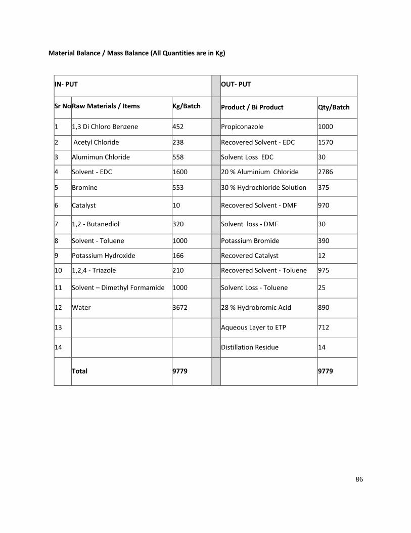
86
Material Balance / Mass Balance (All Quantities are in Kg)
IN- PUT OUT- PUT
Sr No Raw Materials / Items Kg/Batch Product / Bi Product Qty/Batch
1 1,3 Di Chloro Benzene 452 Propiconazole 1000
2 Acetyl Chloride 238 Recovered Solvent - EDC 1570
3 Alumimun Chloride 558 Solvent Loss EDC 30
4 Solvent - EDC 1600 20 % Aluminium Chloride 2786
5 Bromine 553 30 % Hydrochloride Solution 375
6 Catalyst 10 Recovered Solvent - DMF 970
7 1,2 - Butanediol 320 Solvent loss - DMF 30
8 Solvent - Toluene 1000 Potassium Bromide 390
9 Potassium Hydroxide 166 Recovered Catalyst 12
10 1,2,4 - Triazole 210 Recovered Solvent - Toluene 975
11 Solvent – Dimethyl Formamide 1000 Solvent Loss - Toluene 25
12 Water 3672 28 % Hydrobromic Acid 890
13 Aqueous Layer to ETP 712
14 Distillation Residue 14
Total 9779 9779
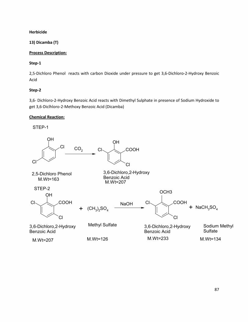
87
OH
Cl
Cl
OH
Cl
Cl COOHCO2
OH
Cl
Cl COOH
(CH3)2SO
4
Cl
Cl COOHNaCH
3SO
4
2,5-Dichloro Phenol 3,6-Dichloro,2-HydroxyBenzoic Acid
3,6-Dichloro,2-HydroxyBenzoic Acid
+
3,6-Dichloro,2-HydroxyBenzoic Acid
OCH3
+
Methyl Sulfate Sodium MethylSulfate
M.Wt=163M.Wt=207
M.Wt=207 M.Wt=126 M.Wt=233
NaOH
M.Wt=134
STEP-1
STEP-2
Herbicide
13) Dicamba (T)
Process Description:
Step-1
2,5-Dichloro Phenol reacts with carbon Dioxide under pressure to get 3,6-Dichloro-2-Hydroxy Benzoic
Acid
Step-2
3,6- Dichloro-2-Hydroxy Benzoic Acid reacts with Dimethyl Sulphate in presence of Sodium Hydroxide to
get 3,6-Diclhloro-2-Methoxy Benzoic Acid (Dicamba)
Chemical Reaction:
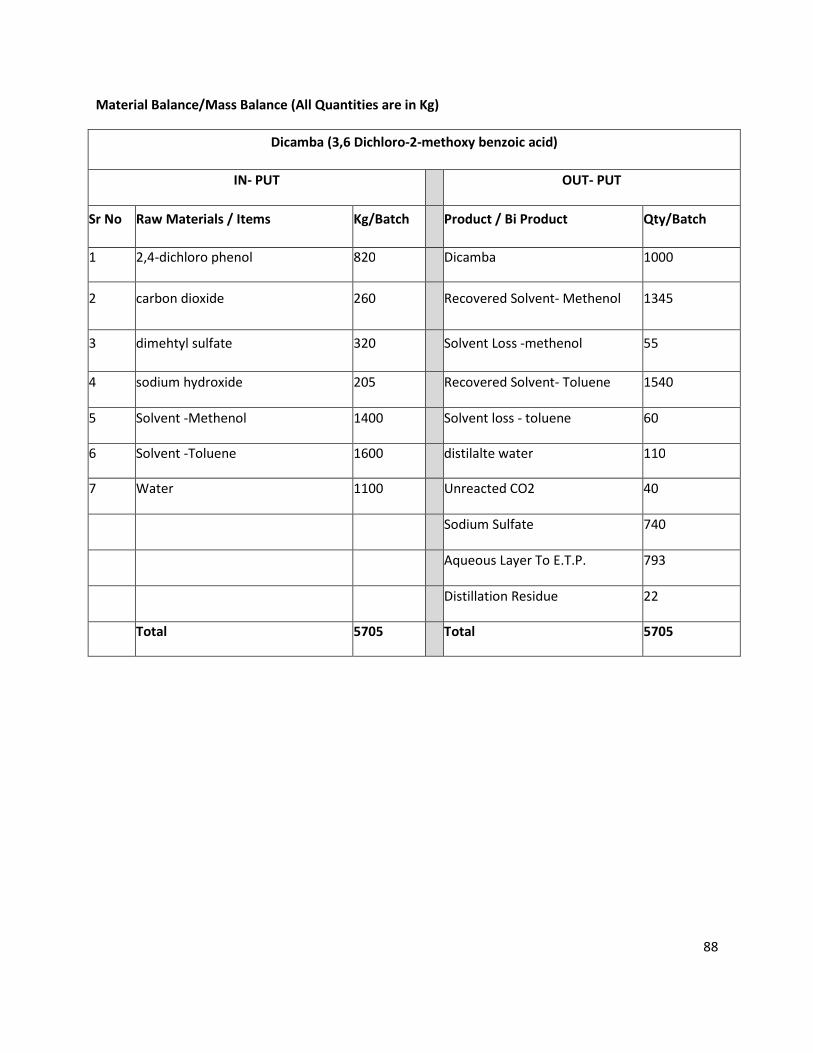
88
Material Balance/Mass Balance (All Quantities are in Kg)
Dicamba (3,6 Dichloro-2-methoxy benzoic acid)
IN- PUT OUT- PUT
Sr No Raw Materials / Items Kg/Batch Product / Bi Product Qty/Batch
1 2,4-dichloro phenol 820 Dicamba 1000
2 carbon dioxide 260 Recovered Solvent- Methenol 1345
3 dimehtyl sulfate 320 Solvent Loss -methenol 55
4 sodium hydroxide 205 Recovered Solvent- Toluene 1540
5 Solvent -Methenol 1400 Solvent loss - toluene 60
6 Solvent -Toluene 1600 distilalte water 110
7 Water 1100 Unreacted CO2 40
Sodium Sulfate 740
Aqueous Layer To E.T.P. 793
Distillation Residue 22
Total 5705 Total 5705
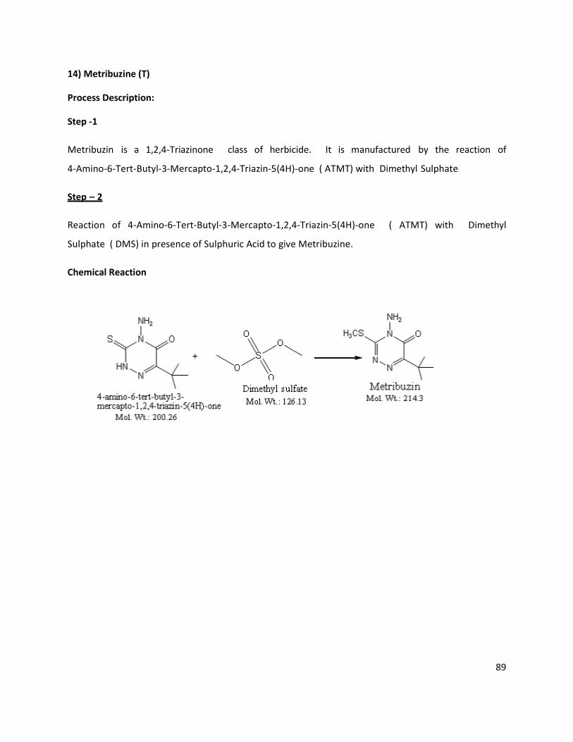
89
14) Metribuzine (T)
Process Description:
Step -1
Metribuzin is a 1,2,4-Triazinone class of herbicide. It is manufactured by the reaction of
4-Amino-6-Tert-Butyl-3-Mercapto-1,2,4-Triazin-5(4H)-one ( ATMT) with Dimethyl Sulphate
Step – 2
Reaction of 4-Amino-6-Tert-Butyl-3-Mercapto-1,2,4-Triazin-5(4H)-one ( ATMT) with Dimethyl
Sulphate ( DMS) in presence of Sulphuric Acid to give Metribuzine.
Chemical Reaction
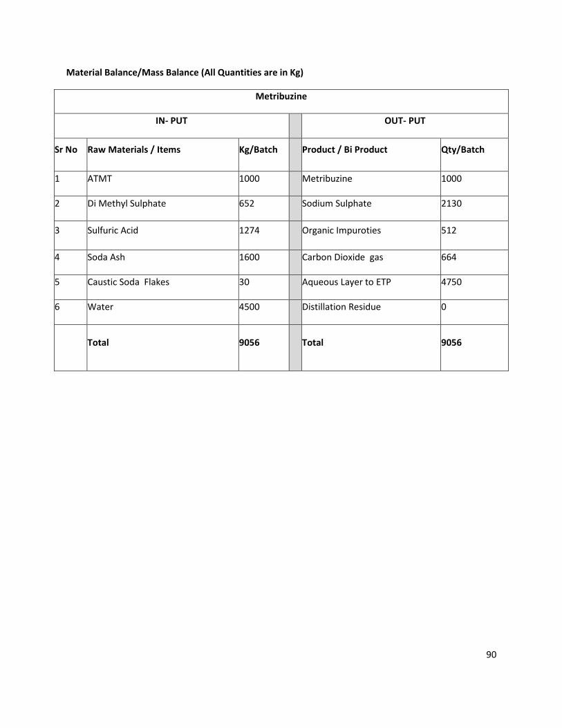
90
Material Balance/Mass Balance (All Quantities are in Kg)
Metribuzine
IN- PUT OUT- PUT
Sr No Raw Materials / Items Kg/Batch Product / Bi Product Qty/Batch
1 ATMT 1000 Metribuzine 1000
2 Di Methyl Sulphate 652 Sodium Sulphate 2130
3 Sulfuric Acid 1274 Organic Impuroties 512
4 Soda Ash 1600 Carbon Dioxide gas 664
5 Caustic Soda Flakes 30 Aqueous Layer to ETP 4750
6 Water 4500 Distillation Residue 0
Total 9056 Total 9056
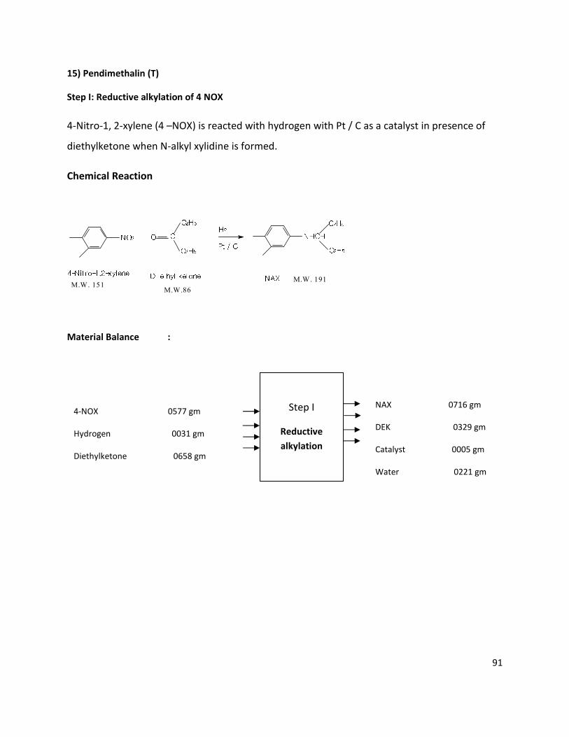
91
NO2
H2
+ O
C
C2H5
C2H5
Pt / C
NHCH
C2H5
C2H5
4-Nitro-1,2-xylene
Di ethyl ketone
NAX
M.W. 151M.W.86
M.W. 191
15) Pendimethalin (T)
Step I: Reductive alkylation of 4 NOX
4-Nitro-1, 2-xylene (4 –NOX) is reacted with hydrogen with Pt / C as a catalyst in presence of
diethylketone when N-alkyl xylidine is formed.
Chemical Reaction
Material Balance :
Step I
Reductive
alkylation
4-NOX 0577 gm
Hydrogen 0031 gm
Diethylketone 0658 gm
NAX 0716 gm
DEK 0329 gm
Catalyst 0005 gm
Water 0221 gm
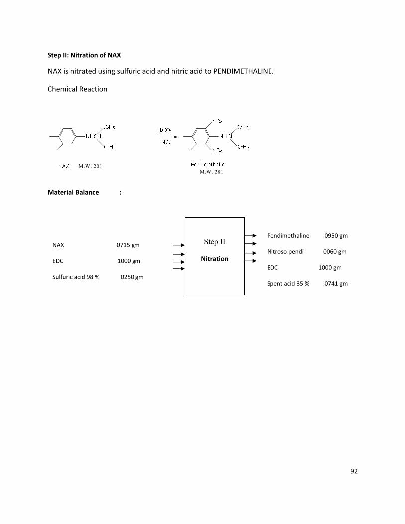
92
NHCH
C2H5
C2H5
NAX
H2SO4
HNO3
C2H5
C2H5
NHCH
NO2
NO2
PendimethalinM.W. 201M.W. 281
Step II: Nitration of NAX
NAX is nitrated using sulfuric acid and nitric acid to PENDIMETHALINE.
Chemical Reaction
Material Balance :
Step II
Nitration
NAX 0715 gm
EDC 1000 gm
Sulfuric acid 98 % 0250 gm
Nitric acid 060 % 0786 gm
Pendimethaline 0950 gm
Nitroso pendi 0060 gm
EDC 1000 gm
Spent acid 35 % 0741 gm
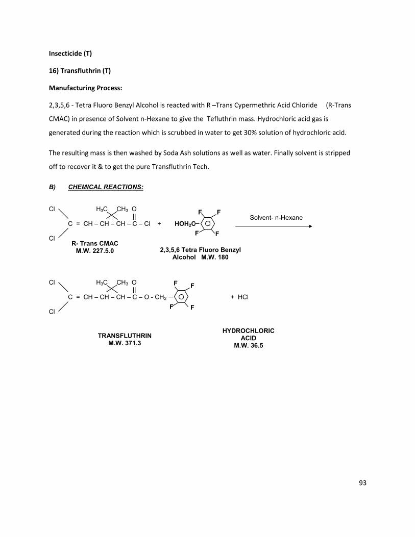
93
B) CHEMICAL REACTIONS: Cl H3C CH3 O || C = CH – CH – CH – C – Cl + Cl Cl H3C CH3 O || C = CH – CH – CH – C – O - CH2 + HCl Cl
Solvent- n-Hexane
R- Trans CMAC M.W. 227.5.0
2,3,5,6 Tetra Fluoro Benzyl Alcohol M.W. 180
TRANSFLUTHRIN M.W. 371.3
HYDROCHLORIC ACID
M.W. 36.5
F
F
F
F
HOH2C
F
F
F
F
Insecticide (T)
16) Transfluthrin (T)
Manufacturing Process:
2,3,5,6 - Tetra Fluoro Benzyl Alcohol is reacted with R –Trans Cypermethric Acid Chloride (R-Trans
CMAC) in presence of Solvent n-Hexane to give the Tefluthrin mass. Hydrochloric acid gas is
generated during the reaction which is scrubbed in water to get 30% solution of hydrochloric acid.
The resulting mass is then washed by Soda Ash solutions as well as water. Finally solvent is stripped
off to recover it & to get the pure Transfluthrin Tech.
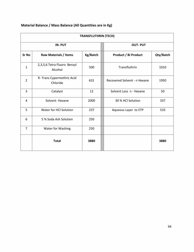
94
Material Balance / Mass Balance (All Quantities are in Kg)
TRANSFLUTHRIN (TECH)
IN- PUT OUT- PUT
Sr No Raw Materials / Items Kg/Batch Product / Bi Product Qty/Batch
1 2,3,5,6 Tetra Fluoro Benzyl
Alcohol 500 Transfluthrin 1010
2 R- Trans Cypermethric Acid
Chloride 631 Recovered Solvent - n Hexane 1950
3 Catalyst 12 Solvent Loss n - Hexane 50
4 Solvent- Hexane 2000 30 % HCl Solution 337
5 Water for HCl Solution 237 Aqueous Layer to ETP 533
6 5 % Soda Ash Solution 250
7 Water for Washing 250
Total 3880 3880
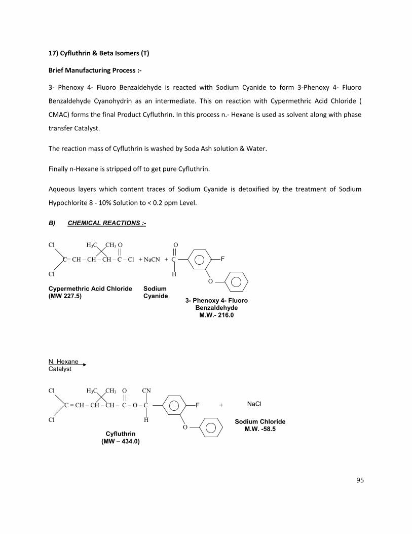
95
B) CHEMICAL REACTIONS :-
Cl H3C CH3 O O
C= CH – CH – CH – C – Cl + NaCN + C
Cl H
O
Cypermethric Acid Chloride Sodium (MW 227.5) Cyanide
N. Hexane Catalyst
Cl H3C CH3 O CN
C = CH – CH – CH – C – O – C +
Cl H
O
NaCl
F
F
3- Phenoxy 4- Fluoro
Benzaldehyde M.W.- 216.0
Sodium Chloride
M.W. -58.5
Cyfluthrin
(MW – 434.0)
17) Cyfluthrin & Beta Isomers (T)
Brief Manufacturing Process :-
3- Phenoxy 4- Fluoro Benzaldehyde is reacted with Sodium Cyanide to form 3-Phenoxy 4- Fluoro
Benzaldehyde Cyanohydrin as an intermediate. This on reaction with Cypermethric Acid Chloride (
CMAC) forms the final Product Cyfluthrin. In this process n.- Hexane is used as solvent along with phase
transfer Catalyst.
The reaction mass of Cyfluthrin is washed by Soda Ash solution & Water.
Finally n-Hexane is stripped off to get pure Cyfluthrin.
Aqueous layers which content traces of Sodium Cyanide is detoxified by the treatment of Sodium
Hypochlorite 8 - 10% Solution to < 0.2 ppm Level.
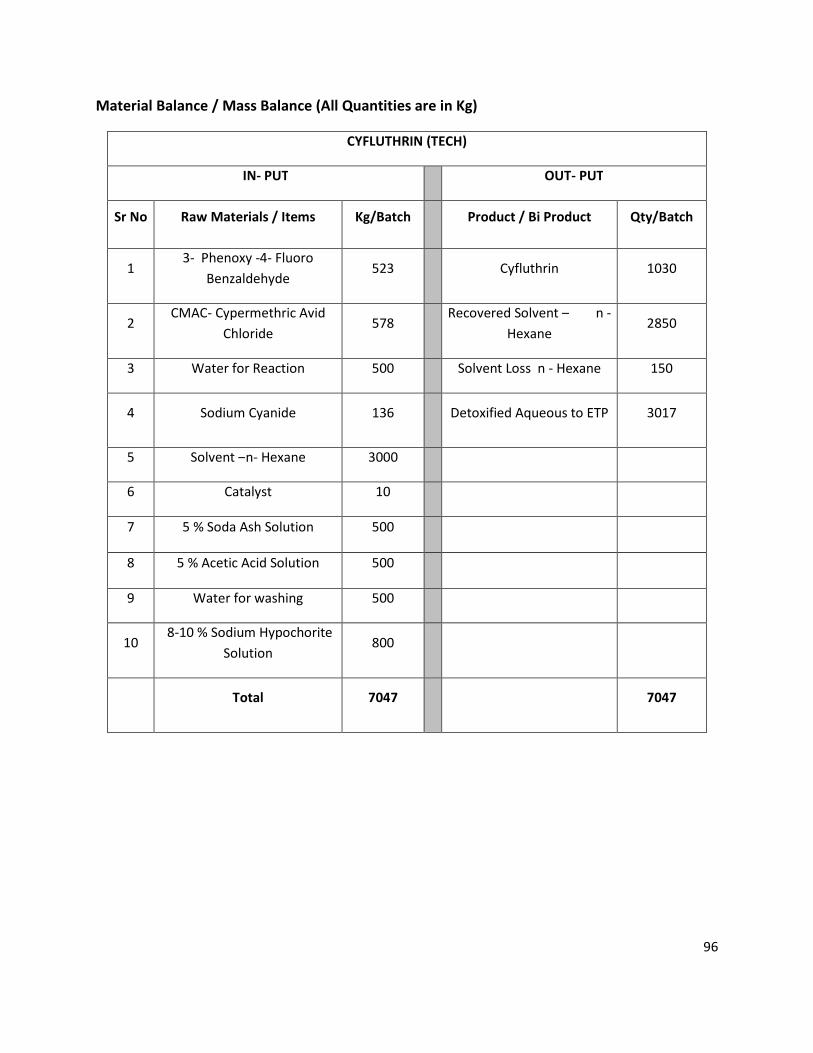
96
Material Balance / Mass Balance (All Quantities are in Kg)
CYFLUTHRIN (TECH)
IN- PUT OUT- PUT
Sr No Raw Materials / Items Kg/Batch Product / Bi Product Qty/Batch
1 3- Phenoxy -4- Fluoro
Benzaldehyde 523 Cyfluthrin 1030
2 CMAC- Cypermethric Avid
Chloride 578
Recovered Solvent – n -
Hexane 2850
3 Water for Reaction 500 Solvent Loss n - Hexane 150
4 Sodium Cyanide 136 Detoxified Aqueous to ETP 3017
5 Solvent –n- Hexane 3000
6 Catalyst 10
7 5 % Soda Ash Solution 500
8 5 % Acetic Acid Solution 500
9 Water for washing 500
10 8-10 % Sodium Hypochorite
Solution 800
Total 7047 7047
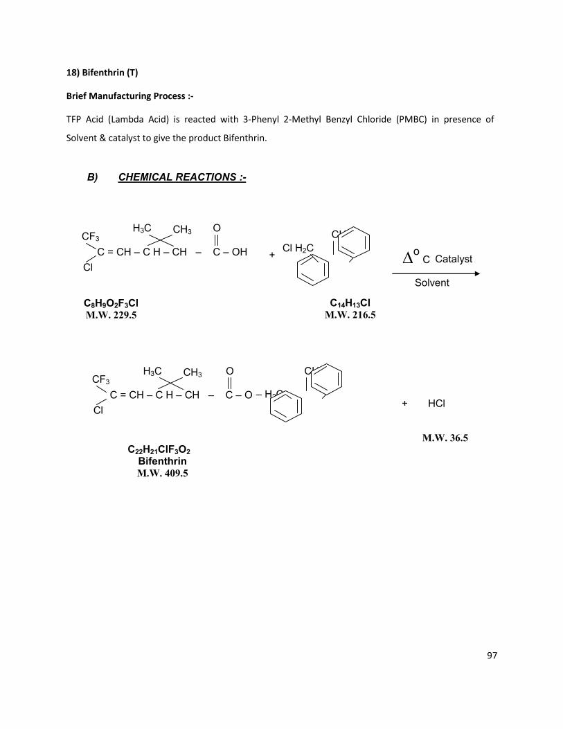
97
B) CHEMICAL REACTIONS :-
C14H13Cl M.W. 216.5
C22H21ClF3O2 Bifenthrin M.W. 409.5
C8H9O2F3Cl M.W. 229.5
+
C = CH – C H – CH – C – OH
CF3
Cl
CH3
H3C
O
CH3 Cl H2C
∆o
C
Catalyst
Solvent
C = CH – C H – CH – C – O
CF3
Cl
CH3
H3C
O
– H2C
CH3
+ HCl
M.W. 36.5
18) Bifenthrin (T)
Brief Manufacturing Process :-
TFP Acid (Lambda Acid) is reacted with 3-Phenyl 2-Methyl Benzyl Chloride (PMBC) in presence of
Solvent & catalyst to give the product Bifenthrin.
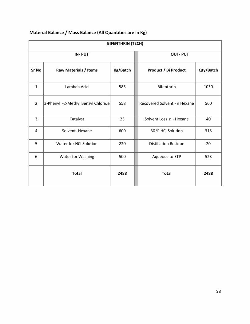
98
Material Balance / Mass Balance (All Quantities are in Kg)
BIFENTHRIN (TECH)
IN- PUT OUT- PUT
Sr No Raw Materials / Items Kg/Batch Product / Bi Product Qty/Batch
1 Lambda Acid 585 Bifenthrin 1030
2 3-Phenyl -2-Methyl Benzyl Chloride 558 Recovered Solvent - n Hexane 560
3 Catalyst 25 Solvent Loss n - Hexane 40
4 Solvent- Hexane 600 30 % HCl Solution 315
5 Water for HCl Solution 220 Distillation Residue 20
6 Water for Washing 500 Aqueous to ETP 523
Total 2488 Total 2488
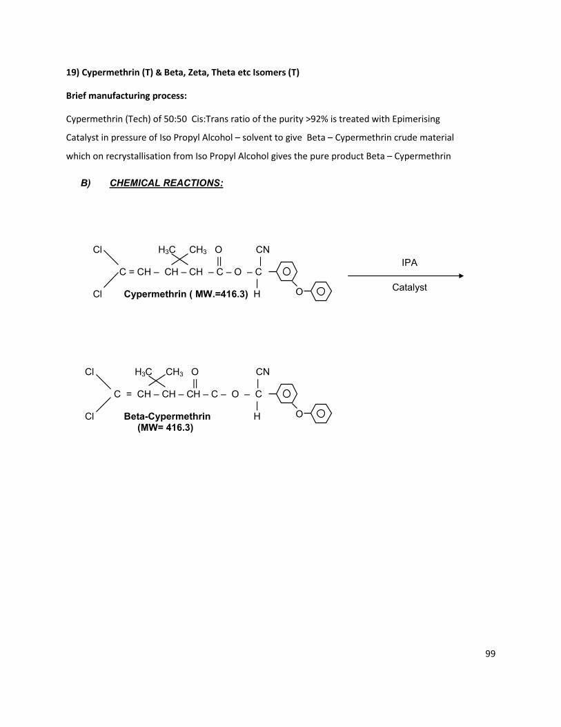
99
B) CHEMICAL REACTIONS: Cl H3C CH3 O CN || | C = CH – CH – CH – C – O – C | Cl Cypermethrin ( MW.=416.3) H Cl H3C CH3 O CN || | C = CH – CH – CH – C – O – C | Cl Beta-Cypermethrin H (MW= 416.3)
O
IPA
Catalyst
O
19) Cypermethrin (T) & Beta, Zeta, Theta etc Isomers (T)
Brief manufacturing process:
Cypermethrin (Tech) of 50:50 Cis:Trans ratio of the purity >92% is treated with Epimerising
Catalyst in pressure of Iso Propyl Alcohol – solvent to give Beta – Cypermethrin crude material
which on recrystallisation from Iso Propyl Alcohol gives the pure product Beta – Cypermethrin
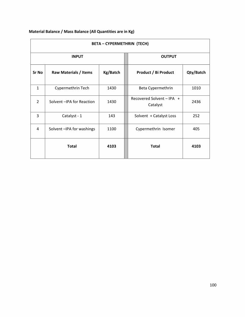
100
Material Balance / Mass Balance (All Quantities are in Kg)
BETA – CYPERMETHRIN (TECH)
INPUT OUTPUT
Sr No Raw Materials / Items Kg/Batch Product / Bi Product Qty/Batch
1 Cypermethrin Tech 1430 Beta Cypermethrin 1010
2 Solvent –IPA for Reaction 1430 Recovered Solvent – IPA +
Catalyst 2436
3 Catalyst - 1 143 Solvent + Catalyst Loss 252
4 Solvent –IPA for washings 1100 Cypermethrin Isomer 405
Total 4103 Total 4103
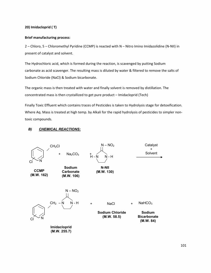
101
B) CHEMICAL REACTIONS:
Cl N
CH2Cl
+ Na2CO3 + H - N N - H
N – NO2 Catalyst +
Solvent
Cl
CH2 – N N - H
N – NO2
+ NaCl +
Imidacloprid
(M.W. 255.7)
NaHCO3
Sodium Chloride
(M.W. 58.5)
Sodium Bicarbonate
(M.W. 84)
CCMP
(M.W. 162)
Sodium Carbonate
(M.W. 106)
N-NII
(M.W. 130)
N
20) Imidacloprid ( T)
Brief manufacturing process:
2 – Chloro, 5 – Chloromethyl Pyridine (CCMP) is reacted with N – Nitro Imino Imidazolidine (N-NII) in
present of catalyst and solvent.
The Hydrochloric acid, which is formed during the reaction, is scavenged by putting Sodium
carbonate as acid scavenger. The resulting mass is diluted by water & filtered to remove the salts of
Sodium Chloride (NaCl) & Sodium bicarbonate.
The organic mass is then treated with water and finally solvent is removed by distillation. The
concentrated mass is then crystallized to get pure product – Imidacloprid (Tech)
Finally Toxic Effluent which contains traces of Pesticides is taken to Hydrolysis stage for detoxification.
Where Aq. Mass is treated at high temp. by Alkali for the rapid hydrolysis of pesticides to simpler non-
toxic compounds.

102
Material Balance / Mass Balance (All Quantities are in Kg)
IMIDACLOPRID (TECH)
IN- PUT OUT- PUT
Sr No Raw Materials / Items Kg/Batch Product / Bi Product Qty/Batch
1 2- Chloro -5- Chloromethyl
Pyridine 900 Imidacloprid 1030
2 N- Nitro N- Methyl Imidazolidine 850 Recovered Solvent DMF 2110
3 Sodium Carbonate 705 Solvent Loss DMF 90
4 Catalyst -1 10 Recovered Solvent Methanol 370
5 Solvent - DMF 2200 Solvent Loss Methanol 30
6 Water for Washings 1000 Aqueous Layer to ETP 2360
7 Caustic Lye 47 % 50 Distillation Residue 125
8 Solvent - Methanol 400
Total 6115 Total 6115

103
Acetamiprid:
Acetamiprid (TECH)
IN- PUT OUT- PUT
Sr No Raw Materials / Items Kg/Batch Product / Bi Product Qty/Batch
1 N-Cyano-N-methylacetamidine 0.440 Acetamiprid 1.00
2 Potassium carbonate 0.620 Recovered Solvent Ethyl
acetate 3.92
3 Ammonium
benzyltriethylchloride 0.020 Solvent Loss Ethyl acetate 0.08
4 DMF (Dimethyl formamide) 1.00 Distillation Residue 0.20
5 2-chloro-5-chloromethyl pyridine 0.728 Effluent 3.608
6 Water for Washings 2.00
7 Ethyl acetate 4.000
8
Total 8.808 Total 8.808
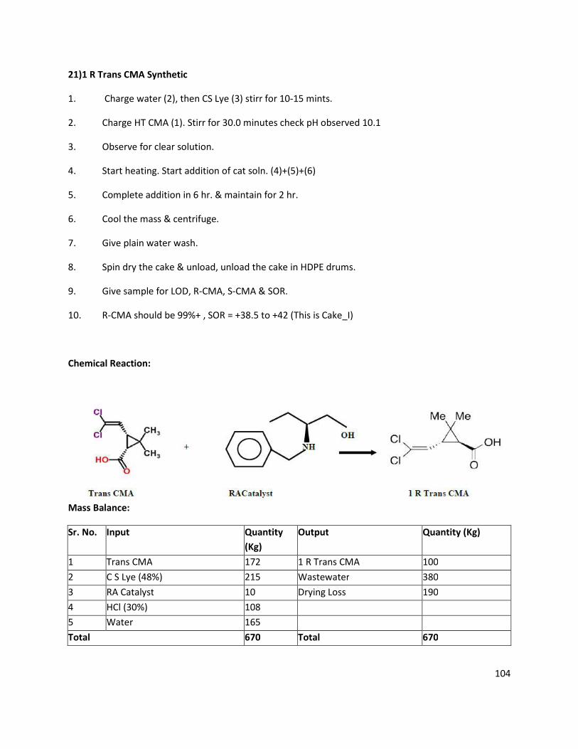
104
21)1 R Trans CMA Synthetic
1. Charge water (2), then CS Lye (3) stirr for 10-15 mints.
2. Charge HT CMA (1). Stirr for 30.0 minutes check pH observed 10.1
3. Observe for clear solution.
4. Start heating. Start addition of cat soln. (4)+(5)+(6)
5. Complete addition in 6 hr. & maintain for 2 hr.
6. Cool the mass & centrifuge.
7. Give plain water wash.
8. Spin dry the cake & unload, unload the cake in HDPE drums.
9. Give sample for LOD, R-CMA, S-CMA & SOR.
10. R-CMA should be 99%+ , SOR = +38.5 to +42 (This is Cake_I)
Chemical Reaction:
Mass Balance:
Sr. No. Input Quantity
(Kg)
Output Quantity (Kg)
1 Trans CMA 172 1 R Trans CMA 100
2 C S Lye (48%) 215 Wastewater 380
3 RA Catalyst 10 Drying Loss 190
4 HCl (30%) 108
5 Water 165
Total 670 Total 670
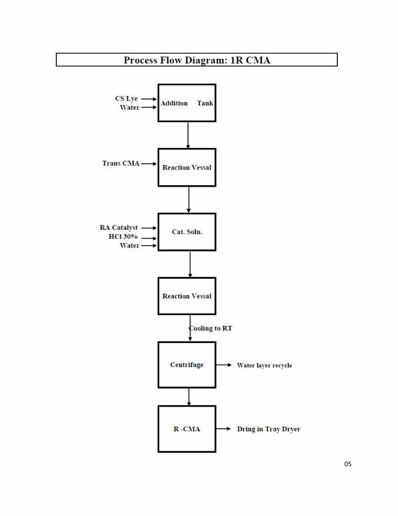
105
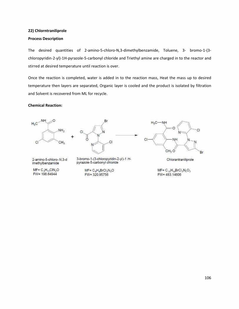
106
22) Chlorntraniliprole
Process Description
The desired quantities of 2-amino-5-chloro-N,3-dimethylbenzamide, Toluene, 3- bromo-1-(3-
chloropyridin-2-yl)-1H-pyrazole-5-carbonyl chloride and Triethyl amine are charged in to the reactor and
stirred at desired temperature until reaction is over.
Once the reaction is completed, water is added in to the reaction mass, Heat the mass up to desired
temperature then layers are separated, Organic layer is cooled and the product is isolated by filtration
and Solvent is recovered from ML for recycle.
Chemical Reaction:

107
Mass Balance:
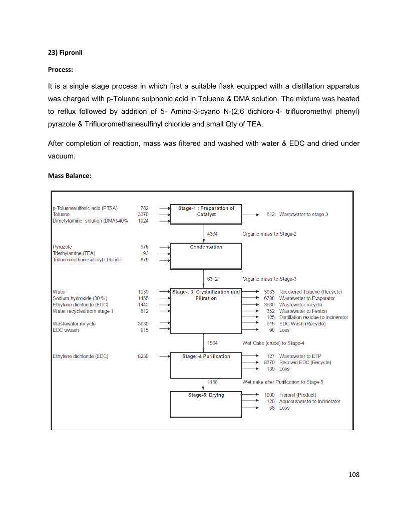
108
23) Fipronil
Process:
It is a single stage process in which first a suitable flask equipped with a distillation apparatus
was charged with p-Toluene sulphonic acid in Toluene & DMA solution. The mixture was heated
to reflux followed by addition of 5- Amino-3-cyano N-(2,6 dichloro-4- trifluoromethyl phenyl)
pyrazole & Trifluoromethanesulfinyl chloride and small Qty of TEA.
After completion of reaction, mass was filtered and washed with water & EDC and dried under
vacuum.
Mass Balance:
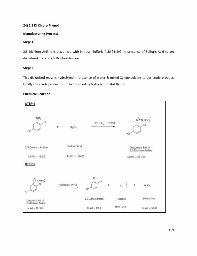
109
24) 2,5 Di Chloro Phenol
Manufacturing Process:
Step: 1
2,5 Dichloro Aniline is diazotized with Nitrosyl Sulfuric Acid ( NSA) in presence of Sulfuric Acid to get
diazotized mass of 2,5 Dichloro Aniline.
Step: 2
This diazotized mass is hydrolyzed in presence of water & mixed Xylene solvent to get crude product.
Finally this crude product is further purified by high vacuum distillation.
Chemical Reaction:
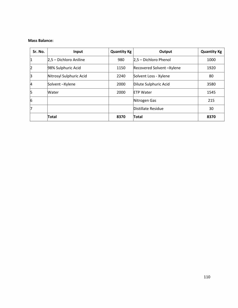
110
Mass Balance:
Sr. No. Input Quantity Kg Output Quantity Kg
1 2,5 – Dichloro Aniline 980 2,5 – Dichloro Phenol 1000
2 98% Sulphuric Acid 1150 Recovered Solvent –Xylene 1920
3 Nitrosyl Sulphuric Acid 2240 Solvent Loss - Xylene 80
4 Solvent –Xylene 2000 Dilute Sulphuric Acid 3580
5 Water 2000 ETP Water 1545
6 Nitrogen Gas 215
7 Distillate Residue 30
Total 8370 Total 8370

111
OCH 2COONa
+ HCl +
OCH 2COOH
NaCl
Cl
Cl Cl
Cl
25) 2,4 Di chloro Phenoxy Acetic Acid (2,4-D ACID)
Manufacturing Process:
Water is charged to the reactor to which is added 2,4-D sodium salt under stirring, after that hydrochloric
acid (30%) is charged. The reaction mass is stirred and filtered to 2,4-D acid.
Effluent: 22000 liters containing sodium chloride.
Chemical Reaction:
Mass Balance:
Sr. No. Input Quantity Kg Output Quantity Kg
1 2,4-D sodium salt 10000 2,4 Di Chloro Phenoxy Acetic Acid 8000
2 HCl (30%) 4500 ETP Water 11500
3 Water 5000
Total 19500 Total 19500
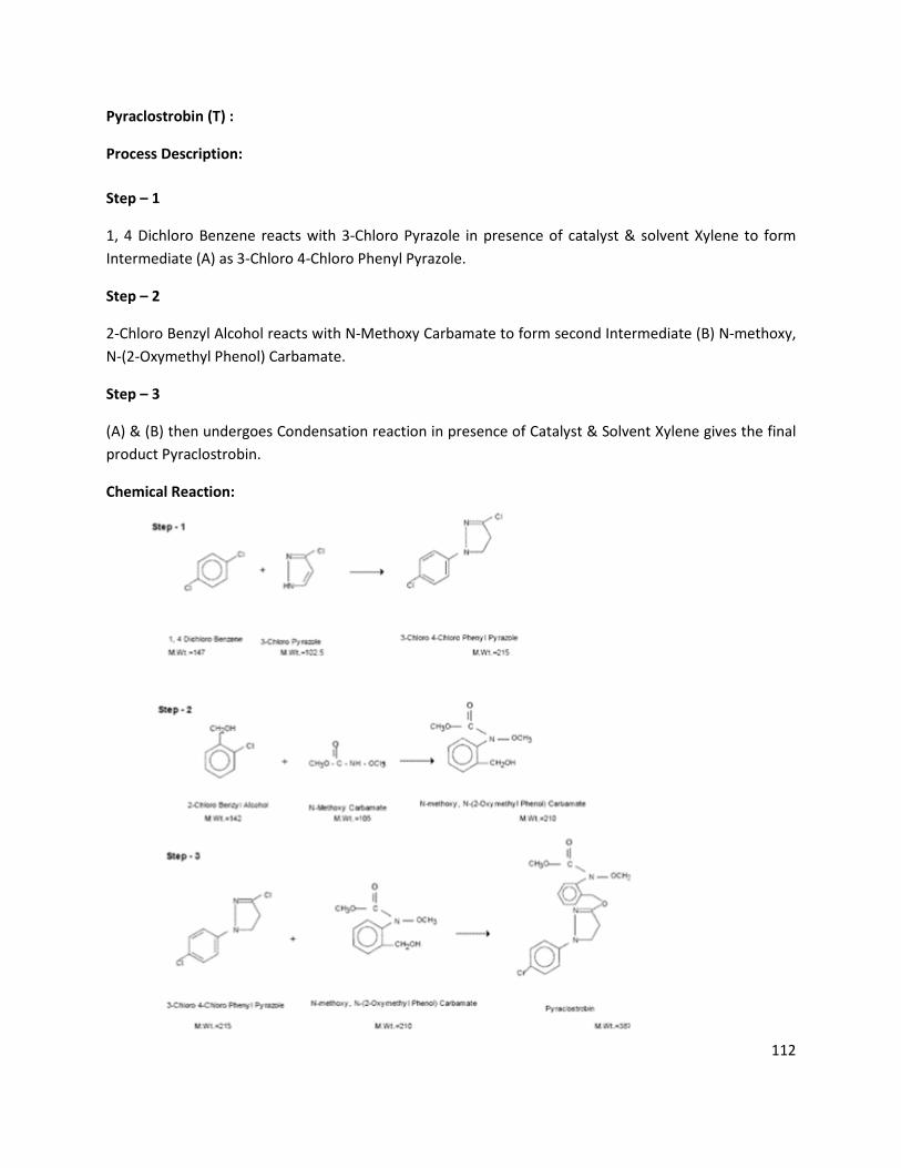
112
Pyraclostrobin (T) :
Process Description:
Step – 1
1, 4 Dichloro Benzene reacts with 3-Chloro Pyrazole in presence of catalyst & solvent Xylene to form
Intermediate (A) as 3-Chloro 4-Chloro Phenyl Pyrazole.
Step – 2
2-Chloro Benzyl Alcohol reacts with N-Methoxy Carbamate to form second Intermediate (B) N-methoxy,
N-(2-Oxymethyl Phenol) Carbamate.
Step – 3
(A) & (B) then undergoes Condensation reaction in presence of Catalyst & Solvent Xylene gives the final
product Pyraclostrobin.
Chemical Reaction:
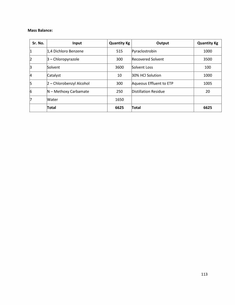
113
Mass Balance:
Sr. No. Input Quantity Kg Output Quantity Kg
1 1,4 Dichloro Benzene 515 Pyraclostrobin 1000
2 3 – Chloropyrazole 300 Recovered Solvent 3500
3 Solvent 3600 Solvent Loss 100
4 Catalyst 10 30% HCl Solution 1000
5 2 – Chlorobenzyl Alcohol 300 Aqueous Effluent to ETP 1005
6 N – Methoxy Carbamate 250 Distillation Residue 20
7 Water 1650
Total 6625 Total 6625

114
ANNEXURE: 4
DETAILS OF WATER CONSUMPTION, WASTEWATER GENERATION AND TREATMANT
BREAK UP OF WATER CONSUMPTION AND WASTEWATER GENERATION
WATER CONSUMPTION:
WATER CONSUMPTION QUANTITY
(KL/DAY)
EIXSTING ADDITIONAL TOAL AFTER
EXPANSION
Domestic 202 23 225
Industrial Process 525 680 1205
Washing 240 160 400
Boiler 650 100 750
Cooling 726 124 850
Total (Industrial) 2141 1064 3205
Others 55 -- 55
Gardening 53 27 80
Total Water Consumption (KL/DAY) 2451 1114 3565
WASTEWATER GENERATION:
WASTEWATER GENERATION QUANTITY
(KL/DAY)
EIXSTING ADDITIONAL TOAL AFTER
EXPANSION
Domestic 145 25 150
Industrial Process 578 522 1100
Washing 240 160 400
Boiler 86 14 100
Cooling 119 11 130
Total (Industrial) 1023 707 1730
Others --- -- --
Gardening --- -- --
Total wastewater Generation KL/DAY) 1168 732 1900
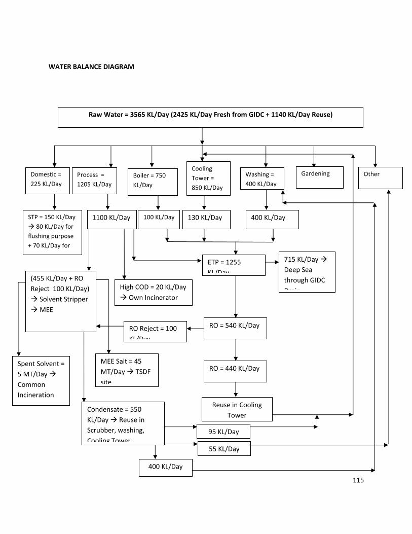
115
WATER BALANCE DIAGRAM
Reuse in Cooling
Tower
Raw Water = 3565 KL/Day (2425 KL/Day Fresh from GIDC + 1140 KL/Day Reuse)
Domestic =
225 KL/Day
Process =
1205 KL/Day
Boiler = 750
KL/Day
Washing =
400 KL/Day
Gardening
= 80 KL/Day
STP = 150 KL/Day
� 80 KL/Day for
flushing purpose
+ 70 KL/Day for
Gardening
1100 KL/Day 100 KL/Day 130 KL/Day
ETP = 1255
KL/Day
Cooling
Tower =
850 KL/Day
400 KL/Day
(455 KL/Day + RO
Reject 100 KL/Day)
� Solvent Stripper
� MEE
Condensate = 550
KL/Day � Reuse in
Scrubber, washing,
Cooling Tower
MEE Salt = 45
MT/Day � TSDF
site
Spent Solvent =
5 MT/Day �
Common
Incineration
site
Other
= 55 KL/Day
High COD = 20 KL/Day
� Own Incinerator
RO = 540 KL/Day
RO = 440 KL/Day
RO Reject = 100
KL/Day
715 KL/Day �
Deep Sea
through GIDC
Drain
95 KL/Day
55 KL/Day
400 KL/Day
116
ANNEXURE: 5
ETP DETAILS
EXISTING
M/s. Hemani Industries Ltd. (Unit-III & IV) have Effluent treatment plant consisting of primary,
secondary and tertiary treatment units. The effluent confirming the GPCB standards is disposed into
deep sea through GIDC pipeline. The details of ETP are as follows.
PROCESS DESCRIPTION: ETP (EFFLUENT TREATMENT PLANT)
M/s. Hemani Industries LTD. (Unit-III & IV) have Effluent treatment plant consisting of primary,
secondary, tertiary treatment and advance treatment units. The details of ETP are as follows.
Stream I (Low COD & TDS Stream)
First all non-toxic and biodegradable streams (low & medium COD& TDS) of wastewater are pass
through Screen Chamber (SC-01) where floating material are removed with help of Screen (S-01). Then
effluent is passed through Oil & Grease Removal Tank (OGRT-01). Automatic mechanical Oil Skimmer is
provided in the OGRT to remove floating oil and grease from the wastewater to Oil & Grease Collection
Tank (OGCT-01). Then effluent is collected in Collection cum Equalization tank-1 (CET-01). Mixer is
provided in CET-01 to keep all suspended solids in suspension.
Then after, equalized wastewater is pumped to Neutralization Tank-1 (NT-01) where the continuous
addition and stirring of Lime solution is done to maintain neutral pH of wastewater from Lime Dosing
Tanks (LDT-01) as per requirement by gravity. Then after, neutralized wastewater goes to Flash Mixer-1
(FM-01) by gravity. Alum and Polyelectrolyte are dosed from Alum Dosing Tank (ADT-01) and
Polyelectrolyte Dosing Tank (PEDT-01) respectively by gravity into FM-1 to carry out coagulation by using
a Flash Mixer. Then after, coagulated wastewater is settled in Primary Clarifier (PCF-01). Clear
supernatant from PCL is passed in Aeration Tank (AT-01)
Here, biodegradation of organic matter of the wastewater is carried out by bacteria (suspended growth)
in the AT-01 and for that oxygen is supplied by 2 nos. of air blowers (B-02) through diffusers. Air blowers
also keep MLSS in suspension.
Then after, wastewater goes to Secondary Clarifier-1 (SCL-01) from AT-1. Here, the suspended solids are
settled. Sludge is removed from bottom of SCL-01 and pumped to AT-1 to maintain MLSS and excess
activated sludge is sent to Sludge Sump (SS-01).
Clear supernatant from SCL-01 shall goes to Aeration Tank-2 (AT-02). Here biodegradation of left out
organic matter of the wastewater is carried out by bacteria (suspended growth) and for that oxygen is
supplied by two nos. of blowers (B-03) with help of diffusers. Then after, wastewater goes to Secondary
Clarifier-2 (SCL-02) from AT-2. Here, the suspended solids are settled. Activated sludge is removed from
bottom of SCL-02 and pumped to AT-02 to maintain MLSS and remaining is sent to SS. Nutrients are
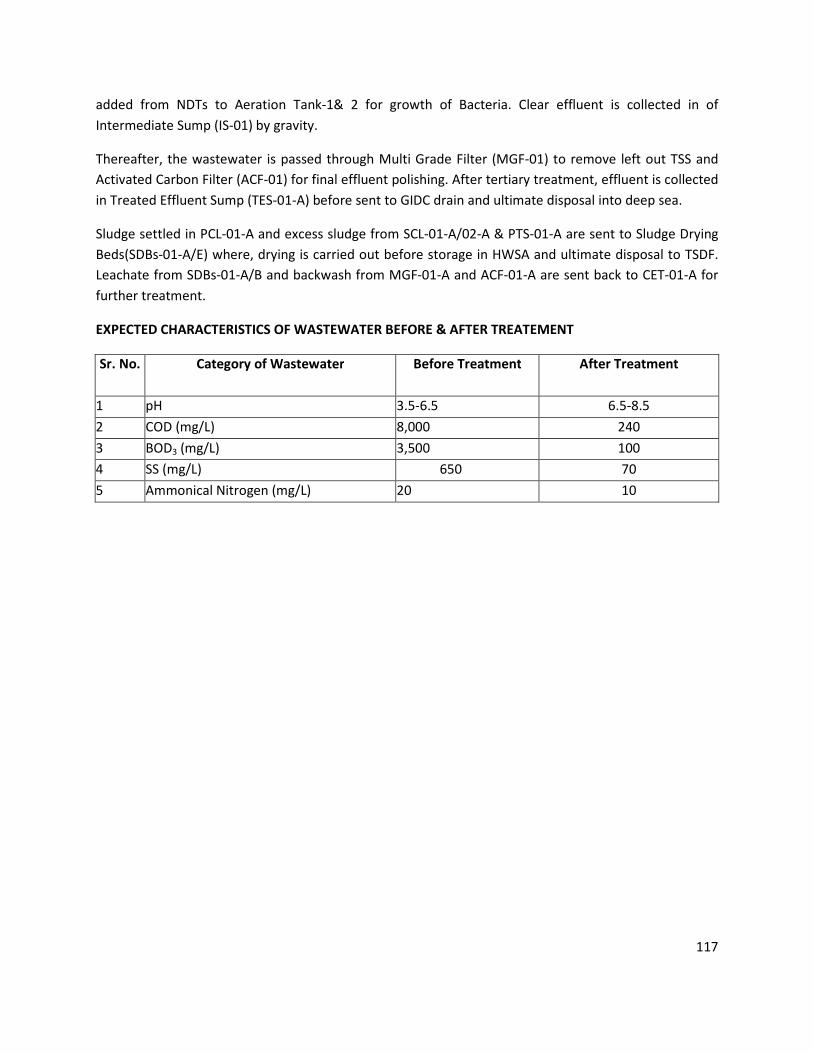
117
added from NDTs to Aeration Tank-1& 2 for growth of Bacteria. Clear effluent is collected in of
Intermediate Sump (IS-01) by gravity.
Thereafter, the wastewater is passed through Multi Grade Filter (MGF-01) to remove left out TSS and
Activated Carbon Filter (ACF-01) for final effluent polishing. After tertiary treatment, effluent is collected
in Treated Effluent Sump (TES-01-A) before sent to GIDC drain and ultimate disposal into deep sea.
Sludge settled in PCL-01-A and excess sludge from SCL-01-A/02-A & PTS-01-A are sent to Sludge Drying
Beds(SDBs-01-A/E) where, drying is carried out before storage in HWSA and ultimate disposal to TSDF.
Leachate from SDBs-01-A/B and backwash from MGF-01-A and ACF-01-A are sent back to CET-01-A for
further treatment.
EXPECTED CHARACTERISTICS OF WASTEWATER BEFORE & AFTER TREATEMENT
Sr. No. Category of Wastewater Before Treatment After Treatment
1 pH 3.5-6.5 6.5-8.5
2 COD (mg/L) 8,000 240
3 BOD3 (mg/L) 3,500 100
4 SS (mg/L) 650 70
5 Ammonical Nitrogen (mg/L) 20 10
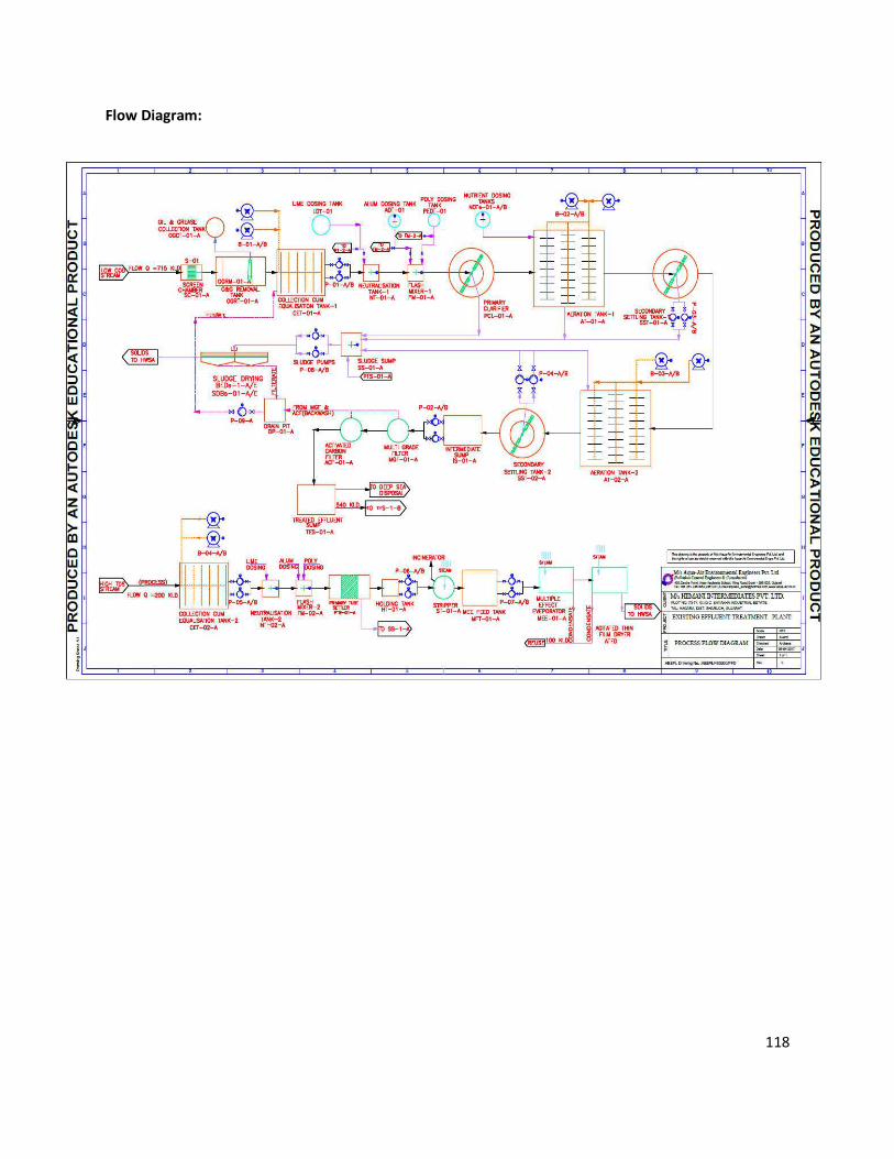
118
Flow Diagram:
119
Stream-II: High TDS
All High TDS streams of wastewater are collected in Collection cum Equalization Tank-2-A (CET-02-A).
Mixer is provided to keep all suspended solids in suspension and to provide proper mixing. Then effluent
is pumped to Neutralization Tank-2(NT-02-A) where Lime is added from Lime Dosing tank. Then after,
effluent is sent to Flash Mixer-2 (FM-2-A) where Alum and poly are added from ADT and PDT
respectively. Then after, coagulated wastewater is settled in Primary Tube Settler (PTS-01-A).
Clear effluent from PTS-1-A is collected in Holding Tank (HT-01-A) before pumped to strippers. Effluent
from stripper is then collected in MEE Feed Tank (MFT-01-A) where RO reject is mixed. Then effluent is
sent to Multiple Effect Evaporator (MEE-01-A) for further treatment followed by Agitated Thin Film
Dryer (ATFD-01-A) for solids dewatering. Condensate from MEE is reused in scrubber, washing and
cooling towers and solids from ATFD-01-A is collected and stored in HWSA for disposal in TSDF.
MEE SYSTEM
PROCESS DESCRIPTION:
Capacity: 200 KL/Day x 3 Nos.
Industry has installed Multi Effect Evaporator for the treatment of industrial effluent (as an
additional facility) having capacity of 600 KL/Day. The condensate water generated from the MEE
is reused in scrubber, washing & cooling tower.
Neutral effluent from Primary Treatment Plant is passed through 3 stages Evaporator System and
the evaporated water is collected in an Evaporated Water Collection Tank and then recycled to
plant after filtering through sand filter and carbon filter. The sludge from the evaporators is filtered
through Nutsch Filter whereby solid filtered sludge is obtained and the filtrate is reused in
scrubber, washing and cooling towers.
Multi stage evaporator (3 - stages) is a long tube forced circulation type evaporators where in the
first effect high pressure steam of 7.0 kg/cm2 is used to evaporate waste water. The evaporated
water in the form of steam at 2.0 kg/cm2g pressure is used for evaporating the effluent in the
second stage at atmospheric pressure. Evaporated water from the second stage is used for
evaporating waste water in the third stage under vacuum of 650- 720 mm Hg. Finally evaporated
water from the third stage is condensed in the steam condenser using cooling water on other side.
Condensate from all the three stages is collected in condensate receiving tanks, which is pure water
and hence, reused in scrubber, washing and cooling towers. Concentrated mass from each effect is
120
collected in the crystallizer where, on cooling inorganic salts are precipitated along with organic
contaminants. This mass is filtered in CF / Nutch filter and filtrate is reused in scrubber, washing
and cooling towers .
Design of MEE :
No. of Effects : 3 (1 Falling Film + 2 Forced Circulation)
Waste Handling Capacity : 200 m3 / day x 3 Nos.
Feed Rate : 10000 kg / hour (20 working hours / day)
Feed Concentration : 10 % TDS
Feed Temperature : 35 o C
Product Rate : 2500 kg / hour
Product Concentration : 40 %
Product Temperature : 55 o C
Water Evaporation Rate : 7500 kg / hour
EXPECTED CHARACTERISTICS OF WASTEWATER BEFORE & AFTER TREATEMENT
Sr. No. Category of Wastewater Before Treatment
1 pH 2-10
2 COD (mg/L) 20,000 - 25,000
3 BOD3 (mg/L) 5,000-6,000
4 TDS (mg/L) 1,10,000
5 Ammonical Nitrogen (mg/L) 200

121
Flow Diagram:
Neutralized effluent
from Primary ETP
Solvent Stripper Column Steam Solvent Evaporation -
Condenser
High COD
Condensate
(Solvent)
�Common
Incinerator
MEE Column-1 Steam Water Evaporation -
Condenser
Condensate
�Reuse in
Process
MEE Column-2 Steam Water Evaporation -
Condenser
MEE Column-3 Steam Water Evaporation -
Condenser
Feed to Evaporator
Steam Condensate
MEE Salt to TSDF Site
for Disposal Site
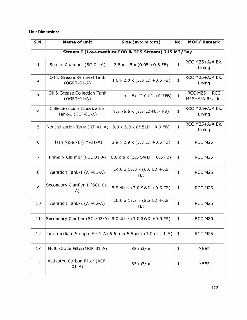
122
Unit Dimension:
S.N. Name of unit Size (m x m x m) No. MOC/ Remark
Stream I (Low-medium COD & TDS Stream) 715 M3/Day
1 Screen Chamber (SC-01-A) 2.8 x 1.5 x (0.05 +0.3 FB) 1 RCC M25+A/A Bk.
Lining
2 Oil & Grease Removal Tank
(OGRT-01-A) 4.0 x 2.0 x (2.0 LD +0.5 FB) 1
RCC M25+A/A Bk.
Lining
3 Oil & Grease Collection Tank
(OGRT-01-A) x 1.5x (2.0 LD +0.7FB) 1
RCC M25 + RCC
M25+A/A Bk. Lin.
4 Collection cum Equalization
Tank-1 (CET-01-A) 8.5 x6.5 x (3.5 LD+0.7 FB) 1
RCC M25+A/A Bk.
Lining
5 Neutralization Tank (NT-01-A) 3.0 x 3.0 x (3.5LD +0.3 FB) 1 RCC M25+A/A Bk.
Lining
6 Flash Mixer-1 (FM-01-A) 2.9 x 2.9 x (3.3 LD +0.5 FB) 1 RCC M25
7 Primary Clarifier (PCL-01-A) 8.0 dia x (3.5 SWD + 0.5 FB) 1 RCC M25
8 Aeration Tank-1 (AT-01-A) 24.0 x 16.0 x (6.0 LD +0.5
FB) 1 RCC M25
9 Secondary Clarifier-1 (SCL-01-
A) 8.5 dia x (3.0 SWD +0.5 FB) 1 RCC M25
10 Aeration Tank-2 (AT-02-A) 20.0 x 15.5 x (5.5 LD +0.5
FB) 1 RCC M25
11 Secondary Clarifier (SCL-02-A) 8.0 dia x (3.0 SWD +0.5 FB) 1 RCC M25
12 Intermediate Sump (IS-01-A) 5.5 m x 5.5 m x (3.0 m + 0.5) 1 RCC M25
13 Multi Grade Filter(MGF-01-A) 35 m3/hr 1 MSEP
14 Activated Carbon Filter (ACF-
01-A) 35 m3/hr 1 MSEP
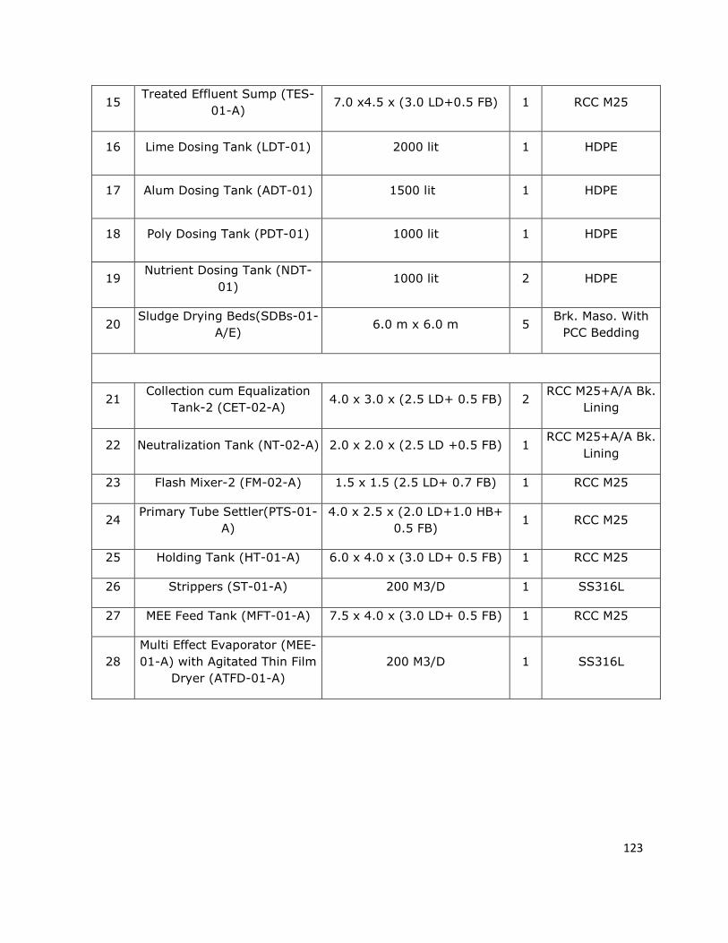
123
15 Treated Effluent Sump (TES-
01-A) 7.0 x4.5 x (3.0 LD+0.5 FB) 1 RCC M25
16 Lime Dosing Tank (LDT-01) 2000 lit 1 HDPE
17 Alum Dosing Tank (ADT-01) 1500 lit 1 HDPE
18 Poly Dosing Tank (PDT-01) 1000 lit 1 HDPE
19 Nutrient Dosing Tank (NDT-
01) 1000 lit 2 HDPE
20 Sludge Drying Beds(SDBs-01-
A/E) 6.0 m x 6.0 m 5
Brk. Maso. With
PCC Bedding
21 Collection cum Equalization
Tank-2 (CET-02-A) 4.0 x 3.0 x (2.5 LD+ 0.5 FB) 2
RCC M25+A/A Bk.
Lining
22 Neutralization Tank (NT-02-A) 2.0 x 2.0 x (2.5 LD +0.5 FB) 1 RCC M25+A/A Bk.
Lining
23 Flash Mixer-2 (FM-02-A) 1.5 x 1.5 (2.5 LD+ 0.7 FB) 1 RCC M25
24 Primary Tube Settler(PTS-01-
A)
4.0 x 2.5 x (2.0 LD+1.0 HB+
0.5 FB) 1 RCC M25
25 Holding Tank (HT-01-A) 6.0 x 4.0 x (3.0 LD+ 0.5 FB) 1 RCC M25
26 Strippers (ST-01-A) 200 M3/D 1 SS316L
27 MEE Feed Tank (MFT-01-A) 7.5 x 4.0 x (3.0 LD+ 0.5 FB) 1 RCC M25
28
Multi Effect Evaporator (MEE-
01-A) with Agitated Thin Film
Dryer (ATFD-01-A)
200 M3/D 1 SS316L
124
Stream-III: High COD
All High COD streams of wastewater are collected in Collection cum Equalization Tank-3 (CET-03). Then
effluent is pumped to Neutralization tank-03 (NT-03) where caustic/Acid are added from Caustic/Acid
Dosing tanks as per requirement to maintain neutral pH of waste water. Then after, neutralized
wastewater is sent to Flash Mixer-03 (FM-03) where Alum and poly are added from Alum Dosing Tank
and Poly Dosing Tank respectively. Then after, coagulated wastewater is settled in Primary Tube Settler-
03 (PTS-03). Sludge settles in PTS-03 is sent to Sludge sump (SS-03) and then pumped to Filter Press (FP)
for dewatering. Neutralized effluent is incinerated in own incinerator.
INCINERATOR SYSTEM
PROCESS DESCRIPTION:
PRIMARY COMBUSTION CHAMBER
The drums containing wastes as well as the organic waste are incinerated into Primary Combustion
Chamber having dual fuel burner (LDO). The organic vapors as well as flue gas are released from
primary Combustion chamber between 150-450 0 C. The temperature of the drums is in the range of
450-750 0 C.
SECONDARY COMBUSTION CHAMBER
The organic vapors and the flue gas are drawn into Secondary Combustion Chamber, which has main
gas burner and dual fuel burner (LDO & NG). The chamber is maintained at sufficiently high
temperature in the range of 900-1200 0 C for complete oxidation of organic/flue gas. i.e complete
incineration.
These hot gases are passed through spray quencher where water is sprayed as cooling agent to cool
down the hot gases from 1200 0C to 150 0C temperature. The cooling water is sprayed through three
spray nozzles. Flue gases are further cooled by mixing atmospheric air through dilution air damper
before passing through scrubbing system.
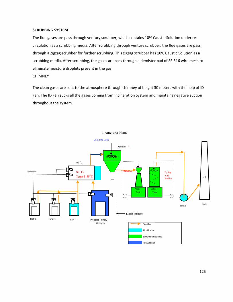
125
Incinerator Plant
Flue Gas
Modification
Equipment Replaced
New Addition
Natural Gas
Quenching Liquid
S C C-
Temp-1150OC
Quenche r
Ash
Zig Zag
Water
Scrubber
StackI D Fan
1150 oC
SDP-3 SDP-2 SDP-1 Proposed Primary
Chamber
Alkali
Tank
Alkali
Tank
Liquid Effluents
Ventury Scrubber
SCRUBBING SYSTEM
The flue gases are pass through ventury scrubber, which contains 10% Caustic Solution under re-
circulation as a scrubbing media. After scrubbing through ventury scrubber, the flue gases are pass
through a Zigzag scrubber for further scrubbing. This zigzag scrubber has 10% Caustic Solution as a
scrubbing media. After scrubbing, the gases are pass through a demister pad of SS-316 wire mesh to
eliminate moisture droplets present in the gas.
CHIMNEY
The clean gases are sent to the atmosphere through chimney of height 30 meters with the help of ID
Fan. The ID Fan sucks all the gases coming from Incineration System and maintains negative suction
throughout the system.
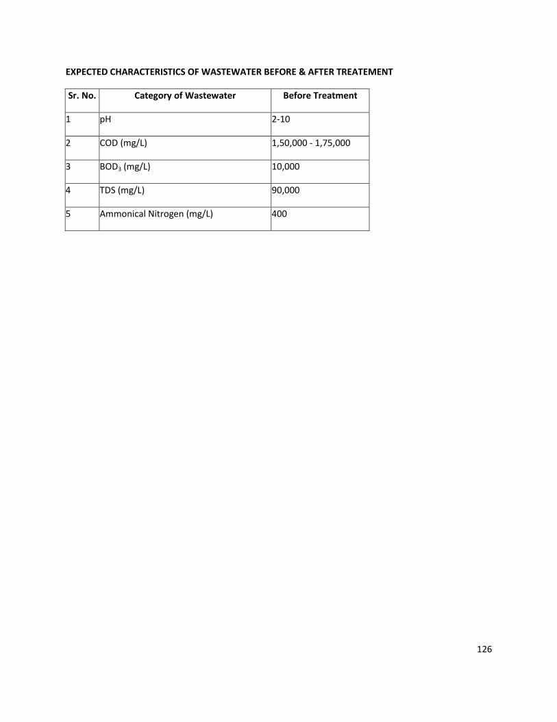
126
EXPECTED CHARACTERISTICS OF WASTEWATER BEFORE & AFTER TREATEMENT
Sr. No. Category of Wastewater Before Treatment
1 pH 2-10
2 COD (mg/L) 1,50,000 - 1,75,000
3 BOD3 (mg/L) 10,000
4 TDS (mg/L) 90,000
5 Ammonical Nitrogen (mg/L) 400
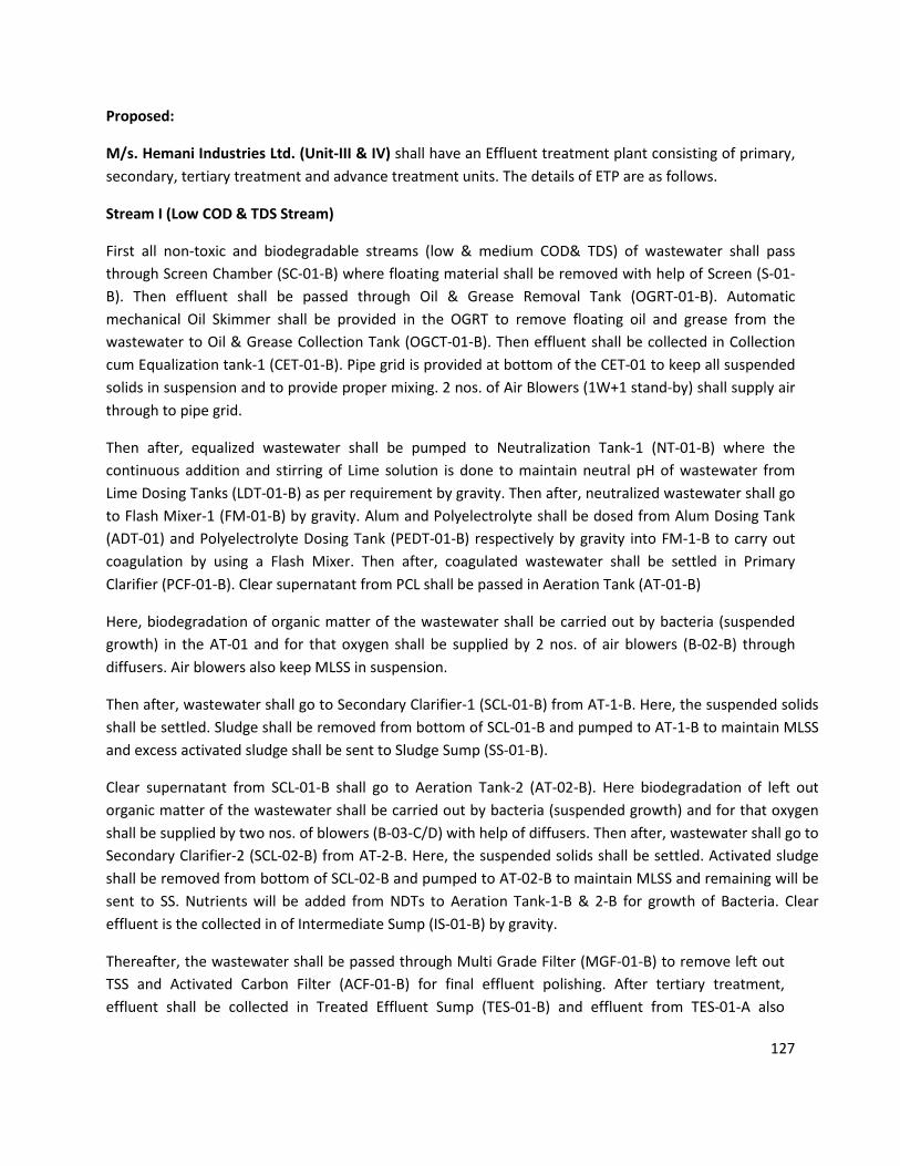
127
Proposed:
M/s. Hemani Industries Ltd. (Unit-III & IV) shall have an Effluent treatment plant consisting of primary,
secondary, tertiary treatment and advance treatment units. The details of ETP are as follows.
Stream I (Low COD & TDS Stream)
First all non-toxic and biodegradable streams (low & medium COD& TDS) of wastewater shall pass
through Screen Chamber (SC-01-B) where floating material shall be removed with help of Screen (S-01-
B). Then effluent shall be passed through Oil & Grease Removal Tank (OGRT-01-B). Automatic
mechanical Oil Skimmer shall be provided in the OGRT to remove floating oil and grease from the
wastewater to Oil & Grease Collection Tank (OGCT-01-B). Then effluent shall be collected in Collection
cum Equalization tank-1 (CET-01-B). Pipe grid is provided at bottom of the CET-01 to keep all suspended
solids in suspension and to provide proper mixing. 2 nos. of Air Blowers (1W+1 stand-by) shall supply air
through to pipe grid.
Then after, equalized wastewater shall be pumped to Neutralization Tank-1 (NT-01-B) where the
continuous addition and stirring of Lime solution is done to maintain neutral pH of wastewater from
Lime Dosing Tanks (LDT-01-B) as per requirement by gravity. Then after, neutralized wastewater shall go
to Flash Mixer-1 (FM-01-B) by gravity. Alum and Polyelectrolyte shall be dosed from Alum Dosing Tank
(ADT-01) and Polyelectrolyte Dosing Tank (PEDT-01-B) respectively by gravity into FM-1-B to carry out
coagulation by using a Flash Mixer. Then after, coagulated wastewater shall be settled in Primary
Clarifier (PCF-01-B). Clear supernatant from PCL shall be passed in Aeration Tank (AT-01-B)
Here, biodegradation of organic matter of the wastewater shall be carried out by bacteria (suspended
growth) in the AT-01 and for that oxygen shall be supplied by 2 nos. of air blowers (B-02-B) through
diffusers. Air blowers also keep MLSS in suspension.
Then after, wastewater shall go to Secondary Clarifier-1 (SCL-01-B) from AT-1-B. Here, the suspended solids
shall be settled. Sludge shall be removed from bottom of SCL-01-B and pumped to AT-1-B to maintain MLSS
and excess activated sludge shall be sent to Sludge Sump (SS-01-B).
Clear supernatant from SCL-01-B shall go to Aeration Tank-2 (AT-02-B). Here biodegradation of left out
organic matter of the wastewater shall be carried out by bacteria (suspended growth) and for that oxygen
shall be supplied by two nos. of blowers (B-03-C/D) with help of diffusers. Then after, wastewater shall go to
Secondary Clarifier-2 (SCL-02-B) from AT-2-B. Here, the suspended solids shall be settled. Activated sludge
shall be removed from bottom of SCL-02-B and pumped to AT-02-B to maintain MLSS and remaining will be
sent to SS. Nutrients will be added from NDTs to Aeration Tank-1-B & 2-B for growth of Bacteria. Clear
effluent is the collected in of Intermediate Sump (IS-01-B) by gravity.
Thereafter, the wastewater shall be passed through Multi Grade Filter (MGF-01-B) to remove left out
TSS and Activated Carbon Filter (ACF-01-B) for final effluent polishing. After tertiary treatment,
effluent shall be collected in Treated Effluent Sump (TES-01-B) and effluent from TES-01-A also
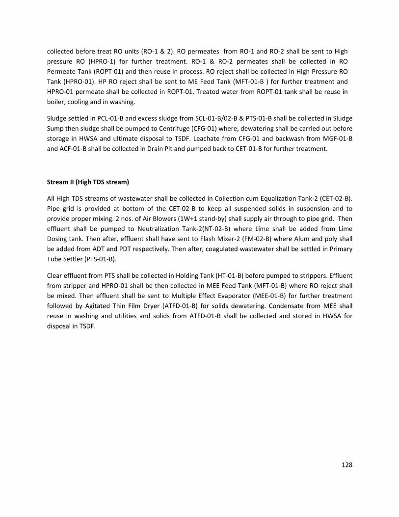
128
collected before treat RO units (RO-1 & 2). RO permeates from RO-1 and RO-2 shall be sent to High
pressure RO (HPRO-1) for further treatment. RO-1 & RO-2 permeates shall be collected in RO
Permeate Tank (ROPT-01) and then reuse in process. RO reject shall be collected in High Pressure RO
Tank (HPRO-01). HP RO reject shall be sent to ME Feed Tank (MFT-01-B ) for further treatment and
HPRO-01 permeate shall be collected in ROPT-01. Treated water from ROPT-01 tank shall be reuse in
boiler, cooling and in washing.
Sludge settled in PCL-01-B and excess sludge from SCL-01-B/02-B & PTS-01-B shall be collected in Sludge
Sump then sludge shall be pumped to Centrifuge (CFG-01) where, dewatering shall be carried out before
storage in HWSA and ultimate disposal to TSDF. Leachate from CFG-01 and backwash from MGF-01-B
and ACF-01-B shall be collected in Drain Pit and pumped back to CET-01-B for further treatment.
Stream II (High TDS stream)
All High TDS streams of wastewater shall be collected in Collection cum Equalization Tank-2 (CET-02-B).
Pipe grid is provided at bottom of the CET-02-B to keep all suspended solids in suspension and to
provide proper mixing. 2 nos. of Air Blowers (1W+1 stand-by) shall supply air through to pipe grid. Then
effluent shall be pumped to Neutralization Tank-2(NT-02-B) where Lime shall be added from Lime
Dosing tank. Then after, effluent shall have sent to Flash Mixer-2 (FM-02-B) where Alum and poly shall
be added from ADT and PDT respectively. Then after, coagulated wastewater shall be settled in Primary
Tube Settler (PTS-01-B).
Clear effluent from PTS shall be collected in Holding Tank (HT-01-B) before pumped to strippers. Effluent
from stripper and HPRO-01 shall be then collected in MEE Feed Tank (MFT-01-B) where RO reject shall
be mixed. Then effluent shall be sent to Multiple Effect Evaporator (MEE-01-B) for further treatment
followed by Agitated Thin Film Dryer (ATFD-01-B) for solids dewatering. Condensate from MEE shall
reuse in washing and utilities and solids from ATFD-01-B shall be collected and stored in HWSA for
disposal in TSDF.
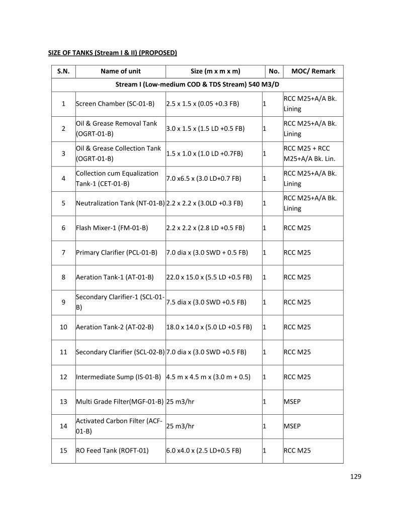
129
SIZE OF TANKS (Stream I & II) (PROPOSED)
S.N. Name of unit Size (m x m x m) No. MOC/ Remark
Stream I (Low-medium COD & TDS Stream) 540 M3/D
1 Screen Chamber (SC-01-B) 2.5 x 1.5 x (0.05 +0.3 FB) 1 RCC M25+A/A Bk.
Lining
2 Oil & Grease Removal Tank
(OGRT-01-B) 3.0 x 1.5 x (1.5 LD +0.5 FB) 1
RCC M25+A/A Bk.
Lining
3 Oil & Grease Collection Tank
(OGRT-01-B) 1.5 x 1.0 x (1.0 LD +0.7FB) 1
RCC M25 + RCC
M25+A/A Bk. Lin.
4 Collection cum Equalization
Tank-1 (CET-01-B) 7.0 x6.5 x (3.0 LD+0.7 FB) 1
RCC M25+A/A Bk.
Lining
5 Neutralization Tank (NT-01-B) 2.2 x 2.2 x (3.0LD +0.3 FB) 1 RCC M25+A/A Bk.
Lining
6 Flash Mixer-1 (FM-01-B) 2.2 x 2.2 x (2.8 LD +0.5 FB) 1 RCC M25
7 Primary Clarifier (PCL-01-B) 7.0 dia x (3.0 SWD + 0.5 FB) 1 RCC M25
8 Aeration Tank-1 (AT-01-B) 22.0 x 15.0 x (5.5 LD +0.5 FB) 1 RCC M25
9 Secondary Clarifier-1 (SCL-01-
B) 7.5 dia x (3.0 SWD +0.5 FB) 1 RCC M25
10 Aeration Tank-2 (AT-02-B) 18.0 x 14.0 x (5.0 LD +0.5 FB) 1 RCC M25
11 Secondary Clarifier (SCL-02-B) 7.0 dia x (3.0 SWD +0.5 FB) 1 RCC M25
12 Intermediate Sump (IS-01-B) 4.5 m x 4.5 m x (3.0 m + 0.5) 1 RCC M25
13 Multi Grade Filter(MGF-01-B) 25 m3/hr 1 MSEP
14 Activated Carbon Filter (ACF-
01-B) 25 m3/hr 1 MSEP
15 RO Feed Tank (ROFT-01) 6.0 x4.0 x (2.5 LD+0.5 FB) 1 RCC M25

130
16 RO-1 & RO-2 270 m3/D (Each) 2 Std.
17 High Pressure RO (HPRO-01) 190 m3/D 1 Std.
18 RO Permeate Tank (ROPT-01) 10.0 x 6.0 (3.0+0.5) 1 RCC M25
19 Lime Dosing Tank (LDT-01) 1500 lit 1 HDPE
20 Alum Dosing Tank (ADT-01) 1000 lit 1 HDPE
21 Poly Dosing Tank (PDT-01) 1000 lit 1 HDPE
22 Nutrient Dosing Tank (NDTs-
01-A/B) 1000 lit 2 HDPE
23 Sludge Sump (SS-01-B) 3.0 m x 3.0 m x (3.0 m + 0.5) 2 RCC M25
24 Centrifuge (CFG-01) 80 M3 2 Brk. Maso. With
PCC Bedding
Stream II (High TDS stream) 255 m3/D+100 m3/D RO Reject
25 Collection cum Equalization
Tank-2 (CET-02) 5.0 x 3.5 x (3.0 LD+ 0.5 FB) 2
RCC M25+A/A Bk.
Lining
26 Neutralization Tank (NT-01) 2.5 x 2.5 x (3.0 LD +0.5 FB) 1 RCC M25+A/A Bk.
Lining
27 Flash Mixer-2 (FM-02) 2.0 x 2.0 (2.8 LD+ 0.7 FB) 1 RCC M25
28 Primary Tube Settler(PTS-01) 4.5 x 3.0 x (2.5 LD+1.0 HB+ 0.5
FB) 1 RCC M25
29 Holding Tank (HT-01) 7.0 x 5.0 x (3.5 LD+ 0.5 FB) 1 RCC M25
30 Strippers (ST-01) 255 M3/D 1 SS316L
31 MEE Feed Tank (MFT-01) 8.5 x 5.0 x (3.5 LD+ 0.5 FB) 1 RCC M25
32
Multi Effect Evaporator (MEE-
01) with Agitated Thin Film
Dryer (ATFD-01)
355 M3/D 1 SS316L
RCC M25 = REINFORCED CEMENT CONCRETE (M 25 GRADE)
PCC = PLAIN CEMENT CONCRETE
MSEP = MILD STEEL EPOXY PAINTED
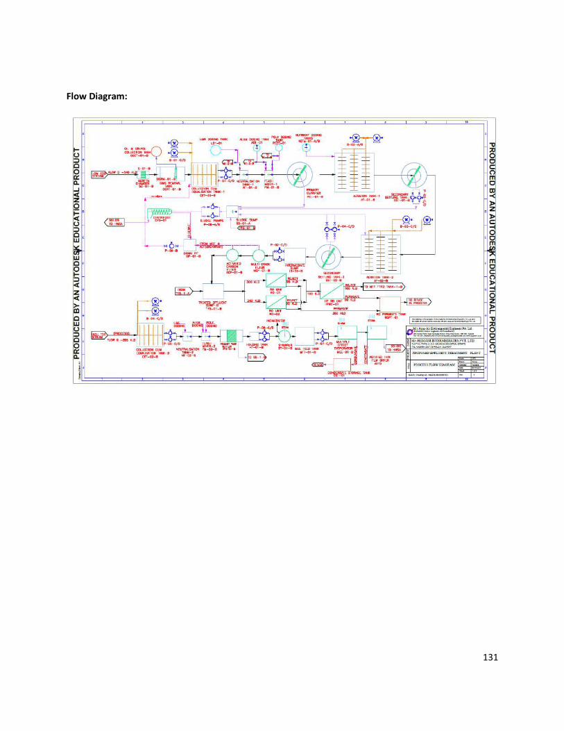
131
Flow Diagram:
132
Details of STP:
DETAILS OF SEWAGE TREATMENT PLANT
First all non-toxic and biodegradable streams of sewage shall be passed through Screen Chamber(SC-01)
where Screen (S-01) is provided to remove floating material from sewage. Then effluent shall be passed
through Oil & Grease Removal Trap (OGRT). Floating oil and grease from the wastewater shall be
removed manually and collected in O & G Collection tank (OGCT) from it. Then after, the sewage is
collected in Collection Tank (CT-01). Then sewage shall be pump to Moving Bed Bio-Reactor (MBBR) with
help of submersible pump (P-01).
In MBBR tank dissolved organics are removed with the help of bacteria in presence of oxygen provided
by centrifugal blower through diffused aeration system. MBBR tank is loaded with special media which
inhibits attached bacterial growth. Due to this attached growth, the quantity of sludge generation is very
little and the treatment is more effective in a very less retention time. This treated sewage shall be
transferred to Tube Settler (TS), where Sludge settles in TS shall be sludge is discarded in sludge drying
beds (SDB) for drying. Leachate from SDBs is sent back to Collection tank for treatment and dry sludge is
used as manure.
The treated sewage shall be then collect in Intermediate Sump (IS) where for disinfection of sewage,
Sodium Hypochlorite shall be added from Sodium Hypochlorite Dosing Tank with help of Dosing Pump.
This treated water shall be pump to Dual Media filter (DMF) with help of Centrifugal pump(P-02). This
treated water pass through Dual Media filter (DMF) to ensure total removal of suspended particles and
for polishing treatment. Treated water is then collected in Treated Water Sump (TWS) having capacity of
one-day storage, before used for irrigation.

133
SIZE OF TANKS
S.N. Name of unit Size (m x m x m)
L x B x (LD+FB) No. MOC/ Remark
STP (150 KLD)
1 Screen Chamber (SC) 3.5 x1.0 x (0.05 LD+0.3 FB) 1 RCC M25
2 Oil & Grease Removal Trap (OGRT) 4.0 x 1.0x (1.2 LD+0.5 FB) 1 RCC M25
3 Collection Tank (CT) 4.0 x 3.0 x (2.8LD+0.7 FB) 1 RCC M25
4 Moving Beds Bio-Rector (MBBR) 4.0 x2.5 x (4.0 LD + 0.3 HB+ 0.3 FB) 1 MSFRP
5 Tube Settler (TS) 3.0 x2.5 x (2.5 LD + 0.5 HB+ 0.3 FB) 1 MSFRP
6 Intermediate Sump (IS) 2.5 x2.0 x (3.0 LD + 0.3 HB+ 0.5 FB) 1 MSFRP
7 Dual media filter(DMF) 7 m3/hr 1 FRP
8 Treated Water Sump(TWS) 5.0 x 5.0 x (3.0 LD+0.5 FB) 1 RCC M25
9 sludge drying beds (SDB) 4.0 x 3.0 2 Brick Mos. With
PCC bedding
10 O & G Collection Tank (OGCT) 500 lit 1 HDPE
11 Sodium Hypo Dosing Tank(SHDT) 750 Lit 1 HDPE
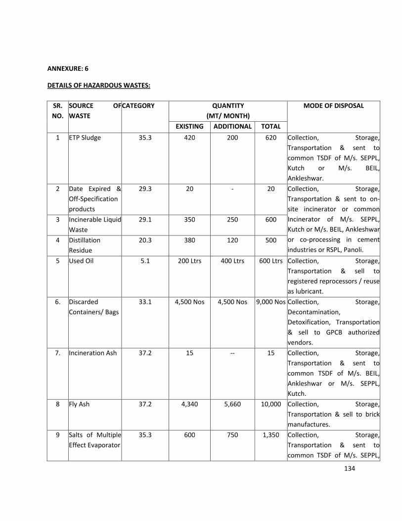
134
ANNEXURE: 6
DETAILS OF HAZARDOUS WASTES:
SR.
NO.
SOURCE OF
WASTE
CATEGORY QUANTITY
(MT/ MONTH)
MODE OF DISPOSAL
EXISTING ADDITIONAL TOTAL
1 ETP Sludge 35.3 420 200 620 Collection, Storage,
Transportation & sent to
common TSDF of M/s. SEPPL,
Kutch or M/s. BEIL,
Ankleshwar.
2 Date Expired &
Off-Specification
products
29.3 20 - 20 Collection, Storage,
Transportation & sent to on-
site incinerator or common
Incinerator of M/s. SEPPL,
Kutch or M/s. BEIL, Ankleshwar
or co-processing in cement
industries or RSPL, Panoli.
3 Incinerable Liquid
Waste
29.1 350 250 600
4 Distillation
Residue
20.3 380 120 500
5 Used Oil 5.1 200 Ltrs 400 Ltrs 600 Ltrs Collection, Storage,
Transportation & sell to
registered reprocessors / reuse
as lubricant.
6. Discarded
Containers/ Bags
33.1 4,500 Nos 4,500 Nos 9,000 Nos Collection, Storage,
Decontamination,
Detoxification, Transportation
& sell to GPCB authorized
vendors.
7. Incineration Ash 37.2 15 -- 15 Collection, Storage,
Transportation & sent to
common TSDF of M/s. BEIL,
Ankleshwar or M/s. SEPPL,
Kutch.
8 Fly Ash 37.2 4,340 5,660 10,000 Collection, Storage,
Transportation & sell to brick
manufactures.
9 Salts of Multiple
Effect Evaporator
35.3 600
750 1,350
Collection, Storage,
Transportation & sent to
common TSDF of M/s. SEPPL,

135
Kutch or M/s. BEIL,
Ankleshwar.
10 30% HCl 29.6 263.75 1,401.25 1,665
Collection, Storage,
Transportation & sell to GPCB
authorized end user.
11 Sodium Sulfite
(80% wet cake)
-- 1,000.25 3,829.75 4,830
12 Ammonium
Chloride (75-80%
wet cake)
-- 425 4,495 4,920
13 Ammonium
Chloride (20-25%
Solution)
-- 1,500 -- 1,500
14 KCl (20-25%
Solution)
-- 1,610 940 2,550
15 Spent Sulphuric
Acid (55%)
29.6 700 405 1,105
16 Sodium Sulphate
Solution (30% to
35%)
-- 2,000 5,240 7,240
17 Potassium
Bromide
-- -- 215 215
18 HBr 29.6 -- 3,153 3,153
19 Cupric Chloride
Solution
-- 85 65 150
20 Cuprous
Hydroxide
-- -- 100 100
21 Sodium Bisulfite -- -- 550 550
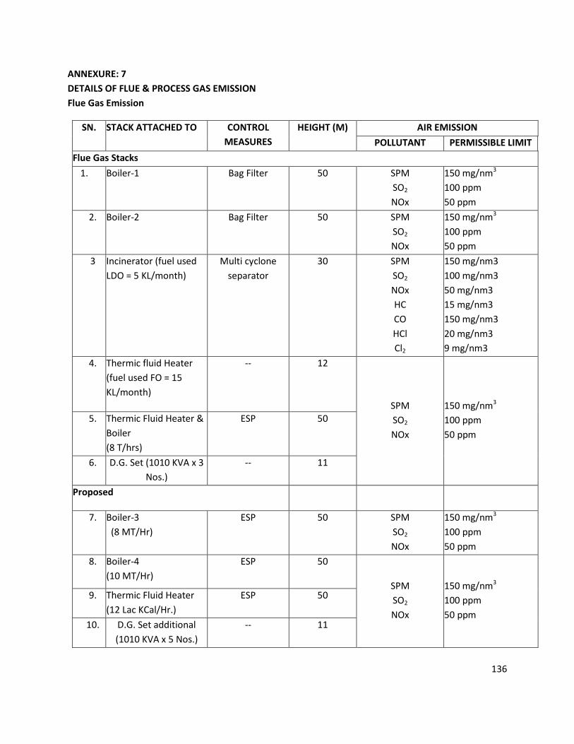
136
ANNEXURE: 7
DETAILS OF FLUE & PROCESS GAS EMISSION
Flue Gas Emission
SN. STACK ATTACHED TO CONTROL
MEASURES
HEIGHT (M) AIR EMISSION
POLLUTANT PERMISSIBLE LIMIT
Flue Gas Stacks
1. Boiler-1
Bag Filter 50 SPM
SO2
NOx
150 mg/nm3
100 ppm
50 ppm
2. Boiler-2
Bag Filter 50 SPM
SO2
NOx
150 mg/nm3
100 ppm
50 ppm
3 Incinerator (fuel used
LDO = 5 KL/month)
Multi cyclone
separator
30 SPM
SO2
NOx
HC
CO
HCl
Cl2
150 mg/nm3
100 mg/nm3
50 mg/nm3
15 mg/nm3
150 mg/nm3
20 mg/nm3
9 mg/nm3
4. Thermic fluid Heater
(fuel used FO = 15
KL/month)
-- 12
SPM
SO2
NOx
150 mg/nm3
100 ppm
50 ppm
5. Thermic Fluid Heater &
Boiler
(8 T/hrs)
ESP 50
6. D.G. Set (1010 KVA x 3
Nos.)
-- 11
Proposed
7. Boiler-3
(8 MT/Hr)
ESP 50 SPM
SO2
NOx
150 mg/nm3
100 ppm
50 ppm
8. Boiler-4
(10 MT/Hr)
ESP 50
SPM
SO2
NOx
150 mg/nm3
100 ppm
50 ppm
9. Thermic Fluid Heater
(12 Lac KCal/Hr.)
ESP 50
10. D.G. Set additional
(1010 KVA x 5 Nos.)
-- 11
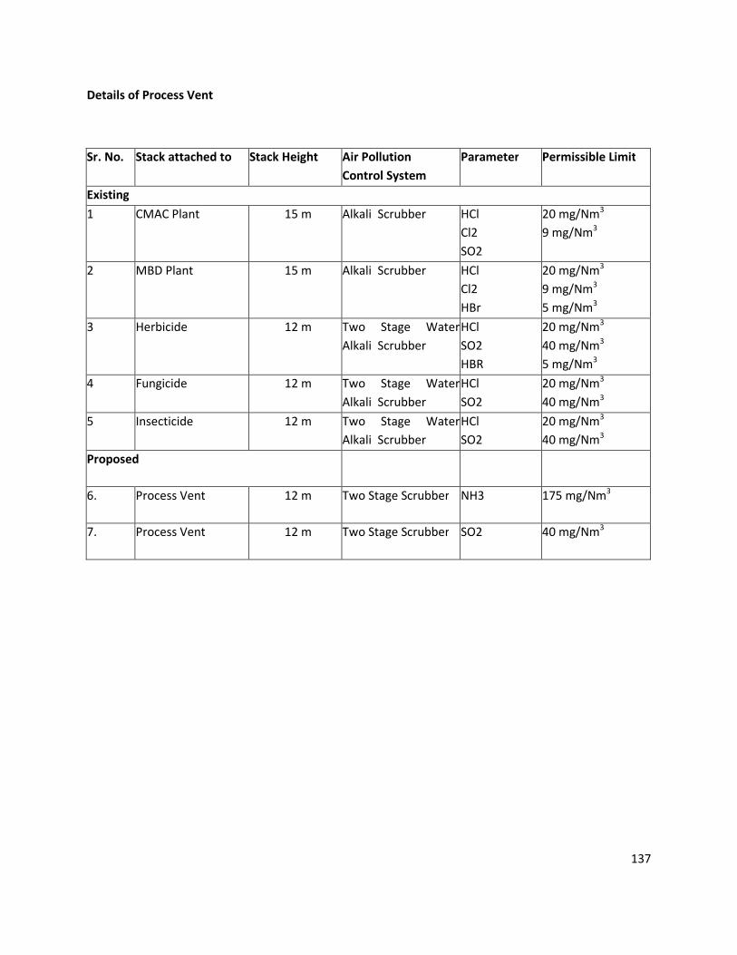
137
Details of Process Vent
Sr. No. Stack attached to Stack Height Air Pollution
Control System
Parameter Permissible Limit
Existing
1 CMAC Plant 15 m Alkali Scrubber HCl
Cl2
SO2
20 mg/Nm3
9 mg/Nm3
2 MBD Plant 15 m Alkali Scrubber HCl
Cl2
HBr
20 mg/Nm3
9 mg/Nm3
5 mg/Nm3
3 Herbicide 12 m Two Stage Water
Alkali Scrubber
HCl
SO2
HBR
20 mg/Nm3
40 mg/Nm3
5 mg/Nm3
4 Fungicide 12 m Two Stage Water
Alkali Scrubber
HCl
SO2
20 mg/Nm3
40 mg/Nm3
5 Insecticide 12 m Two Stage Water
Alkali Scrubber
HCl
SO2
20 mg/Nm3
40 mg/Nm3
Proposed
6. Process Vent 12 m Two Stage Scrubber NH3 175 mg/Nm3
7. Process Vent 12 m Two Stage Scrubber SO2 40 mg/Nm3
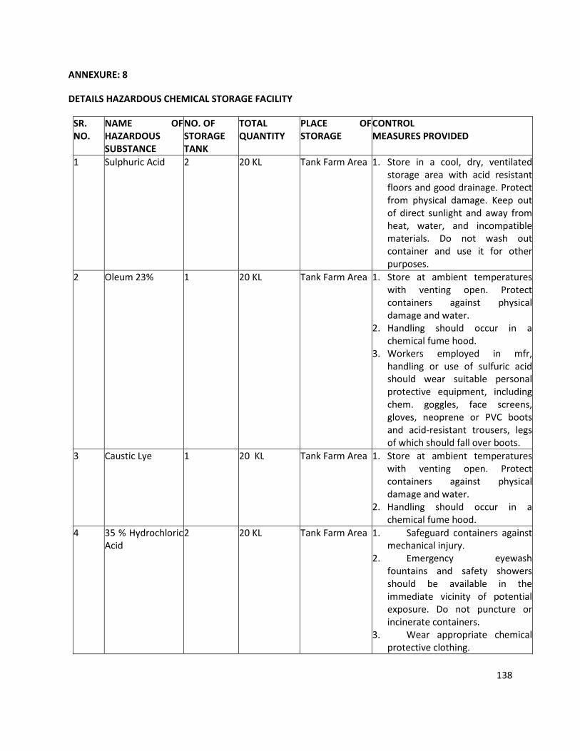
138
ANNEXURE: 8
DETAILS HAZARDOUS CHEMICAL STORAGE FACILITY
SR.
NO.
NAME OF
HAZARDOUS
SUBSTANCE
NO. OF
STORAGE
TANK
TOTAL
QUANTITY
PLACE OF
STORAGE
CONTROL
MEASURES PROVIDED
1 Sulphuric Acid 2 20 KL Tank Farm Area 1. Store in a cool, dry, ventilated
storage area with acid resistant
floors and good drainage. Protect
from physical damage. Keep out
of direct sunlight and away from
heat, water, and incompatible
materials. Do not wash out
container and use it for other
purposes.
2 Oleum 23% 1 20 KL Tank Farm Area 1. Store at ambient temperatures
with venting open. Protect
containers against physical
damage and water.
2. Handling should occur in a
chemical fume hood.
3. Workers employed in mfr,
handling or use of sulfuric acid
should wear suitable personal
protective equipment, including
chem. goggles, face screens,
gloves, neoprene or PVC boots
and acid-resistant trousers, legs
of which should fall over boots.
3 Caustic Lye 1 20 KL Tank Farm Area 1. Store at ambient temperatures
with venting open. Protect
containers against physical
damage and water.
2. Handling should occur in a
chemical fume hood.
4 35 % Hydrochloric
Acid
2 20 KL Tank Farm Area 1. Safeguard containers against
mechanical injury.
2. Emergency eyewash
fountains and safety showers
should be available in the
immediate vicinity of potential
exposure. Do not puncture or
incinerate containers.
3. Wear appropriate chemical
protective clothing.
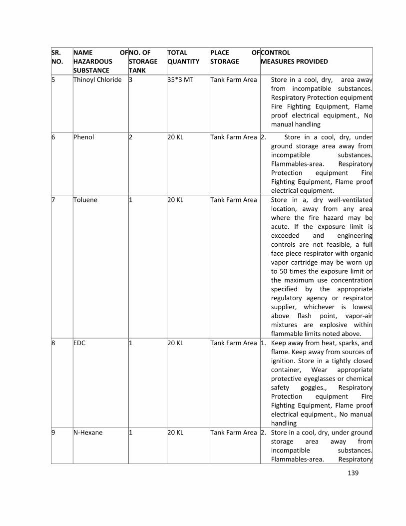
139
SR.
NO.
NAME OF
HAZARDOUS
SUBSTANCE
NO. OF
STORAGE
TANK
TOTAL
QUANTITY
PLACE OF
STORAGE
CONTROL
MEASURES PROVIDED
5 Thinoyl Chloride 3 35*3 MT Tank Farm Area Store in a cool, dry, area away
from incompatible substances.
Respiratory Protection equipment
Fire Fighting Equipment, Flame
proof electrical equipment., No
manual handling
6 Phenol 2 20 KL Tank Farm Area
2. Store in a cool, dry, under
ground storage area away from
incompatible substances.
Flammables-area. Respiratory
Protection equipment Fire
Fighting Equipment, Flame proof
electrical equipment.
7 Toluene 1 20 KL Tank Farm Area Store in a, dry well-ventilated
location, away from any area
where the fire hazard may be
acute. If the exposure limit is
exceeded and engineering
controls are not feasible, a full
face piece respirator with organic
vapor cartridge may be worn up
to 50 times the exposure limit or
the maximum use concentration
specified by the appropriate
regulatory agency or respirator
supplier, whichever is lowest
above flash point, vapor-air
mixtures are explosive within
flammable limits noted above.
8 EDC 1 20 KL Tank Farm Area 1. Keep away from heat, sparks, and
flame. Keep away from sources of
ignition. Store in a tightly closed
container, Wear appropriate
protective eyeglasses or chemical
safety goggles., Respiratory
Protection equipment Fire
Fighting Equipment, Flame proof
electrical equipment., No manual
handling
9 N-Hexane 1 20 KL Tank Farm Area 2. Store in a cool, dry, under ground
storage area away from
incompatible substances.
Flammables-area. Respiratory
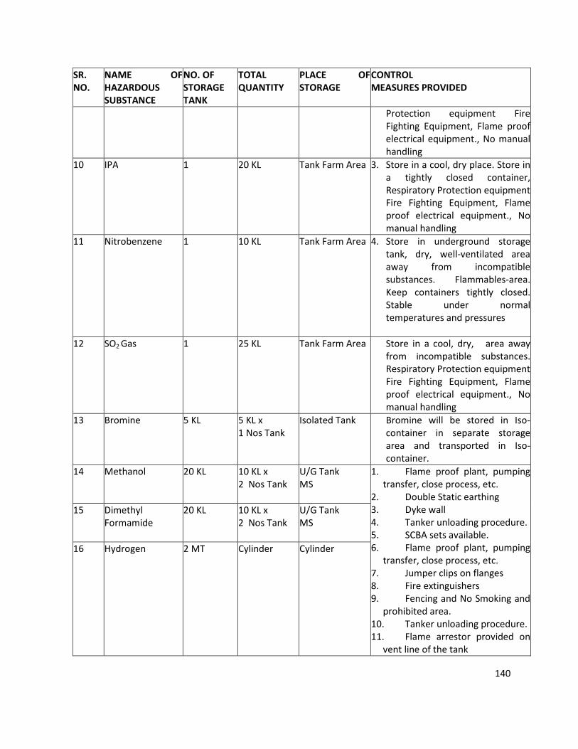
140
SR.
NO.
NAME OF
HAZARDOUS
SUBSTANCE
NO. OF
STORAGE
TANK
TOTAL
QUANTITY
PLACE OF
STORAGE
CONTROL
MEASURES PROVIDED
Protection equipment Fire
Fighting Equipment, Flame proof
electrical equipment., No manual
handling
10 IPA 1 20 KL Tank Farm Area 3. Store in a cool, dry place. Store in
a tightly closed container,
Respiratory Protection equipment
Fire Fighting Equipment, Flame
proof electrical equipment., No
manual handling
11 Nitrobenzene 1 10 KL Tank Farm Area 4. Store in underground storage
tank, dry, well-ventilated area
away from incompatible
substances. Flammables-area.
Keep containers tightly closed.
Stable under normal
temperatures and pressures
12 SO2 Gas 1 25 KL Tank Farm Area Store in a cool, dry, area away
from incompatible substances.
Respiratory Protection equipment
Fire Fighting Equipment, Flame
proof electrical equipment., No
manual handling
13 Bromine 5 KL 5 KL x
1 Nos Tank
Isolated Tank Bromine will be stored in Iso-
container in separate storage
area and transported in Iso-
container.
14 Methanol 20 KL 10 KL x
2 Nos Tank
U/G Tank
MS
1. Flame proof plant, pumping
transfer, close process, etc.
2. Double Static earthing
3. Dyke wall
4. Tanker unloading procedure.
5. SCBA sets available.
6. Flame proof plant, pumping
transfer, close process, etc.
7. Jumper clips on flanges
8. Fire extinguishers
9. Fencing and No Smoking and
prohibited area.
10. Tanker unloading procedure.
11. Flame arrestor provided on
vent line of the tank
15 Dimethyl
Formamide
20 KL 10 KL x
2 Nos Tank
U/G Tank
MS
16 Hydrogen 2 MT Cylinder Cylinder
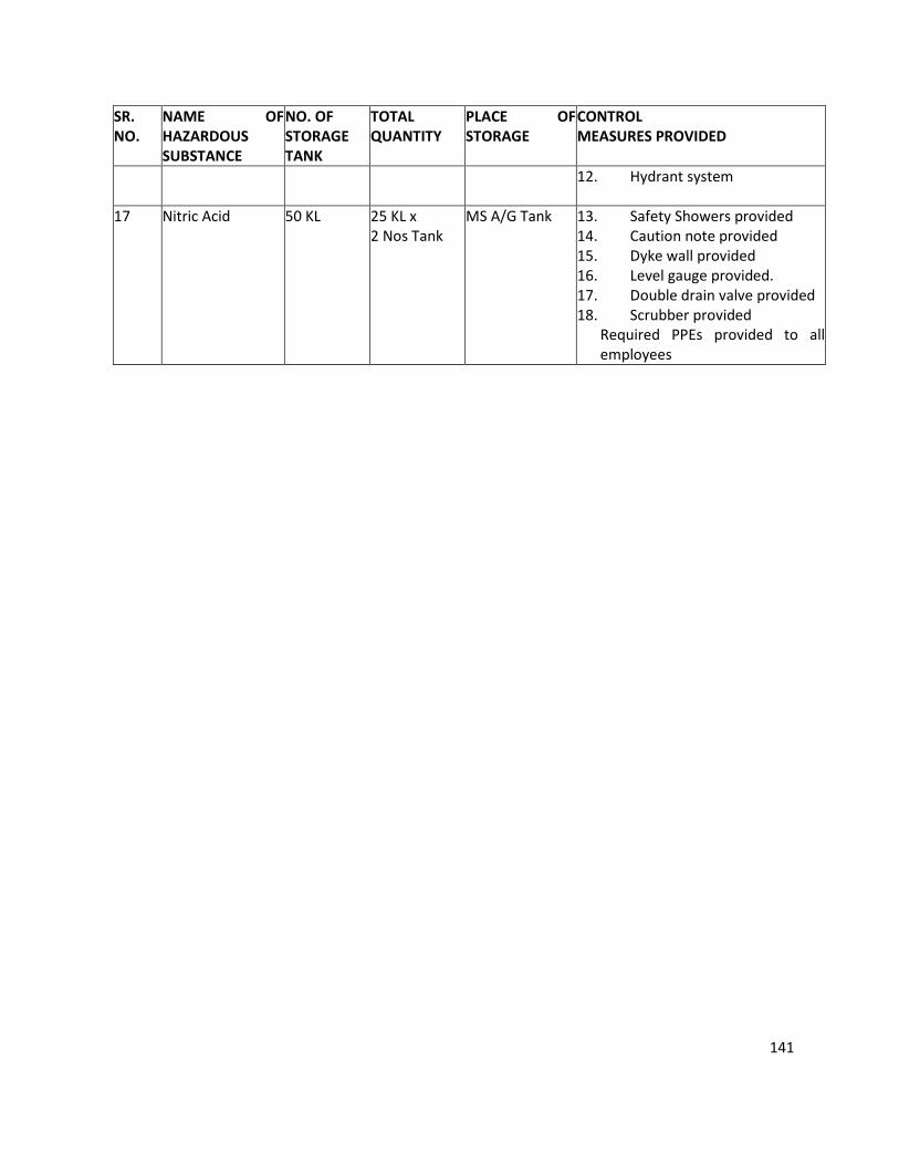
141
SR.
NO.
NAME OF
HAZARDOUS
SUBSTANCE
NO. OF
STORAGE
TANK
TOTAL
QUANTITY
PLACE OF
STORAGE
CONTROL
MEASURES PROVIDED
12. Hydrant system
17 Nitric Acid 50 KL 25 KL x
2 Nos Tank
MS A/G Tank 13. Safety Showers provided
14. Caution note provided
15. Dyke wall provided
16. Level gauge provided.
17. Double drain valve provided
18. Scrubber provided
Required PPEs provided to all
employees
142
ANNEXURE 9
SOCIO - ECONOMIC IMPACTS
1) EMPLOYMENT OPPORTUNITIES
The manpower requirement for the proposed project is expected to generate some permanent jobs and
secondary jobs for the operation and maintenance of plant. This will increase direct / indirect employment
opportunities and ancillary business development to some extent for the local population. This phase is
expected to create a beneficial impact on the local socio-economic environment.
2) INDUSTRIES
Required raw materials and skilled and unskilled labors will be utilized maximum from the local area. The
increasing industrial activity will boost the commercial and economical status of the locality, to some
extent.
3) PUBLIC HEALTH
The company regularly examines, inspects and tests its emission from sources to make sure that the
emission is below the permissible limit. Hence, there will not be any significant change in the status of
sanitation and the community health of the area, as sufficient measures have been taken and proposed
under the EMP.
4) TRANSPORTATION AND COMMUNICATION
In brief, as a result of the proposed project there will be no adverse impact on sanitation, communication
and community health, as sufficient measures have been proposed to be taken under the EMP. The
proposed project is not expected to make any significant change in the existing status of the socio -
economic environment of this region.
143
ANNEXURE – 10
PROPOSED DRAFT TERMS OF REFERENCE:
1. Project Description
1. Justification of project.
2. Promoters and their back ground
3. Project site location along with site map of 5 km area and site details providing various industries,
surface water bodies, forests etc.
4. Project cost
5. Project location and Plant layout.
6. Water source and utilization including proposed water balance.
7. Product spectrum (proposed products along with production capacity) and process
8. List of hazardous chemicals.
9. Mass balance of each product
10. Storage and Transportation of raw materials and products.
2. Description of the Environment and Baseline Data Collection
1. Micrometeorological data for wind speed, direction, temperature, humidity and rainfall in 5 km area.
2. Existing environmental status Vis a Vis air, water, noise, soil in 5 km area from the project site. For
SPM, RSPM, SO2, NOx.
3. Ground water quality at 5 locations within 5 km.
4. Complete water balance
3. Socio Economic Data
1. Existing socio-economic status, land use pattern and infrastructure facilities available in the study area
were surveyed.
4. Impacts Identification And Mitigatory Measures
1. Identification of impacting activities from the proposed project during construction and operational phase.
2. Impact on air and mitigation measures including green belt
3. Impact on water environment and mitigation measures
4. Soil pollution source and mitigation measures
5. Noise generation and control.
6. Solid waste quantification and disposal.
5. Environmental Management Plan
1. Details of pollution control measures
2. Environment management team
3. Proposed schedule for environmental monitoring including post project
6. Risk Assessment
1. Objectives and methodology of risk assessment
144
2. Details on storage facilities
3. Process safety, transportation, fire fighting systems, safety features and emergency capabilities to be
adopted.
4. Identification of hazards
5. Consequence analysis through occurrence & evaluation of incidents
6. Disaster Management Plan.
7. Information for Control of Fugitive Emissions
8. Post Project Monitoring Plan for Air, Water, Soil and Noise.
9. Information on Rain Water Harvesting
10. Green Belt Development plan
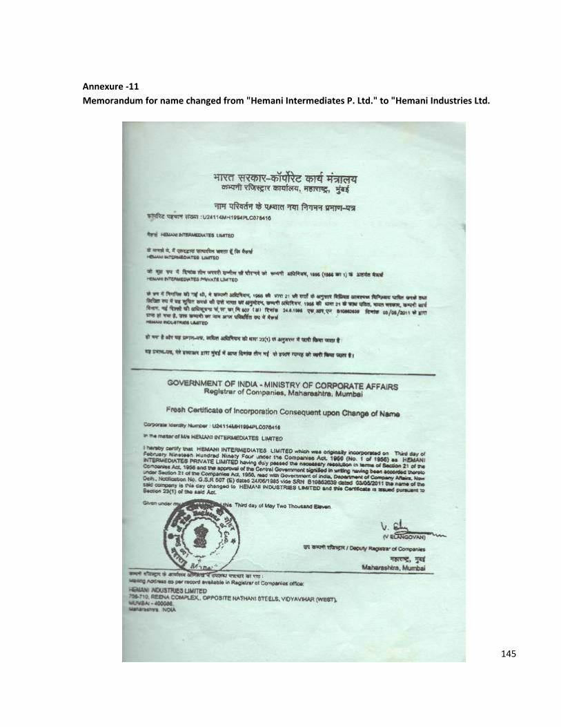
145
Annexure -11
Memorandum for name changed from "Hemani Intermediates P. Ltd." to "Hemani Industries Ltd.
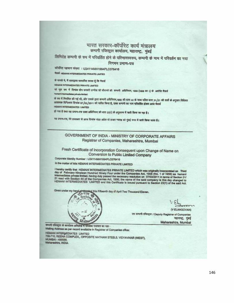
146

147
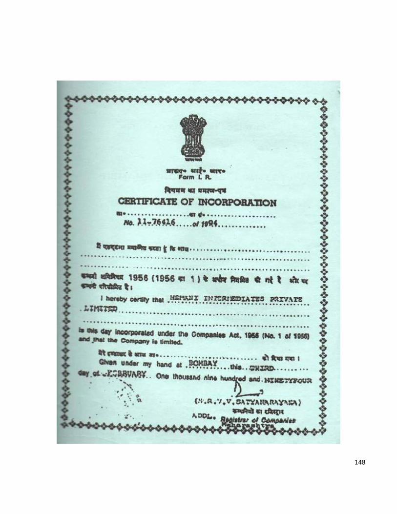
148
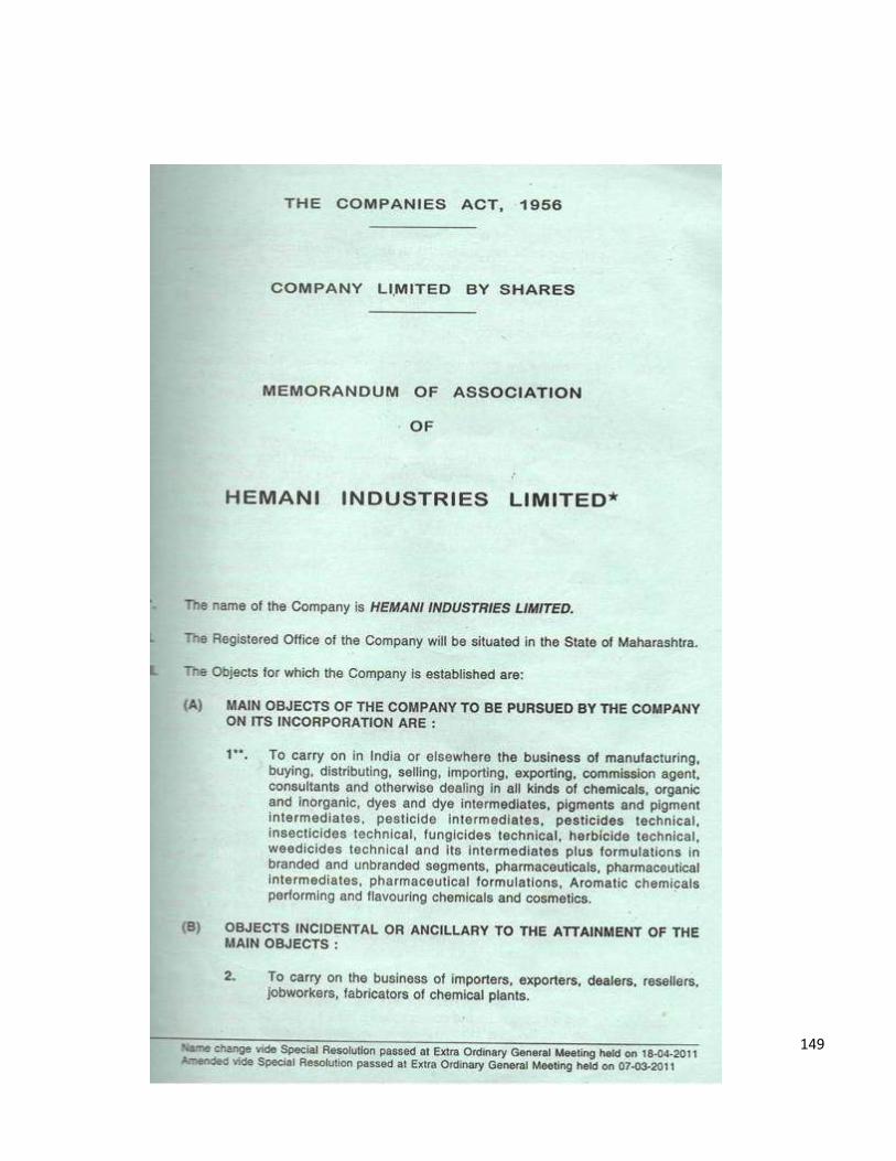
149
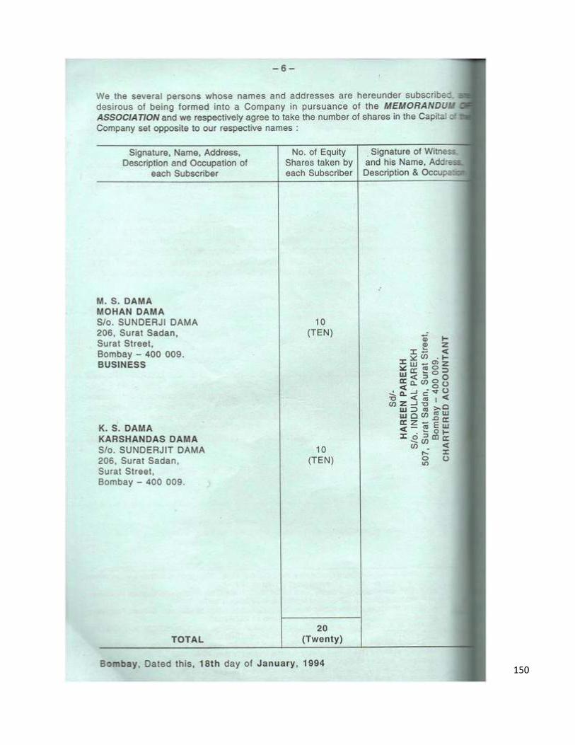
150
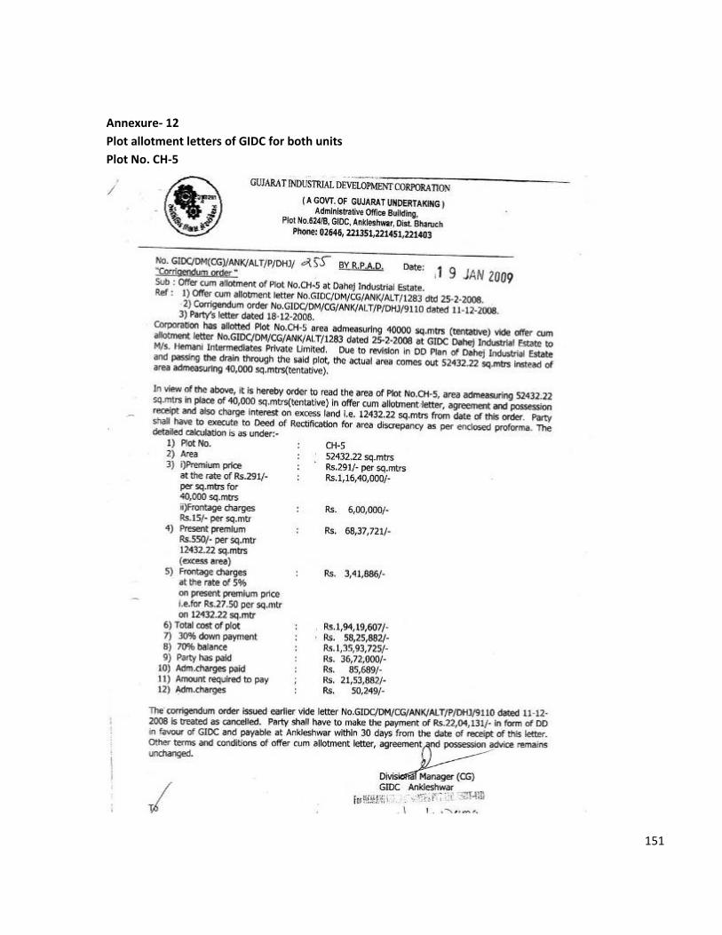
151
Annexure- 12
Plot allotment letters of GIDC for both units
Plot No. CH-5
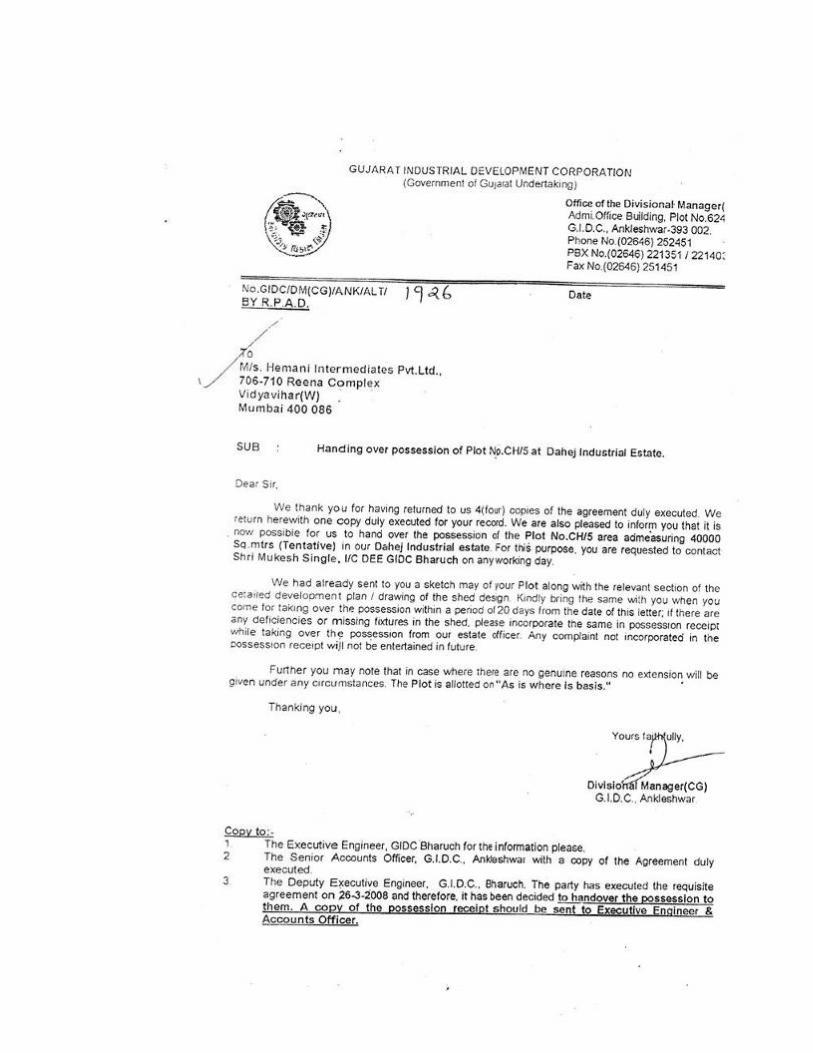
152

153
Plot No. E-362
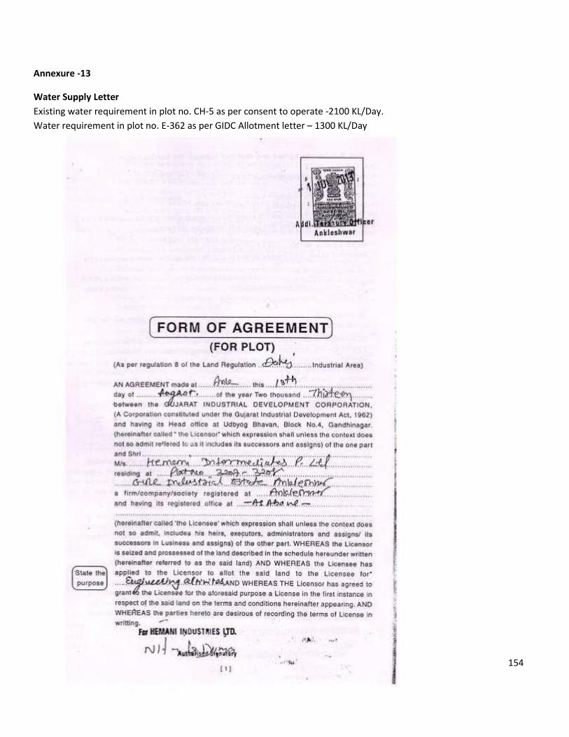
154
Annexure -13
Water Supply Letter
Existing water requirement in plot no. CH-5 as per consent to operate -2100 KL/Day.
Water requirement in plot no. E-362 as per GIDC Allotment letter – 1300 KL/Day
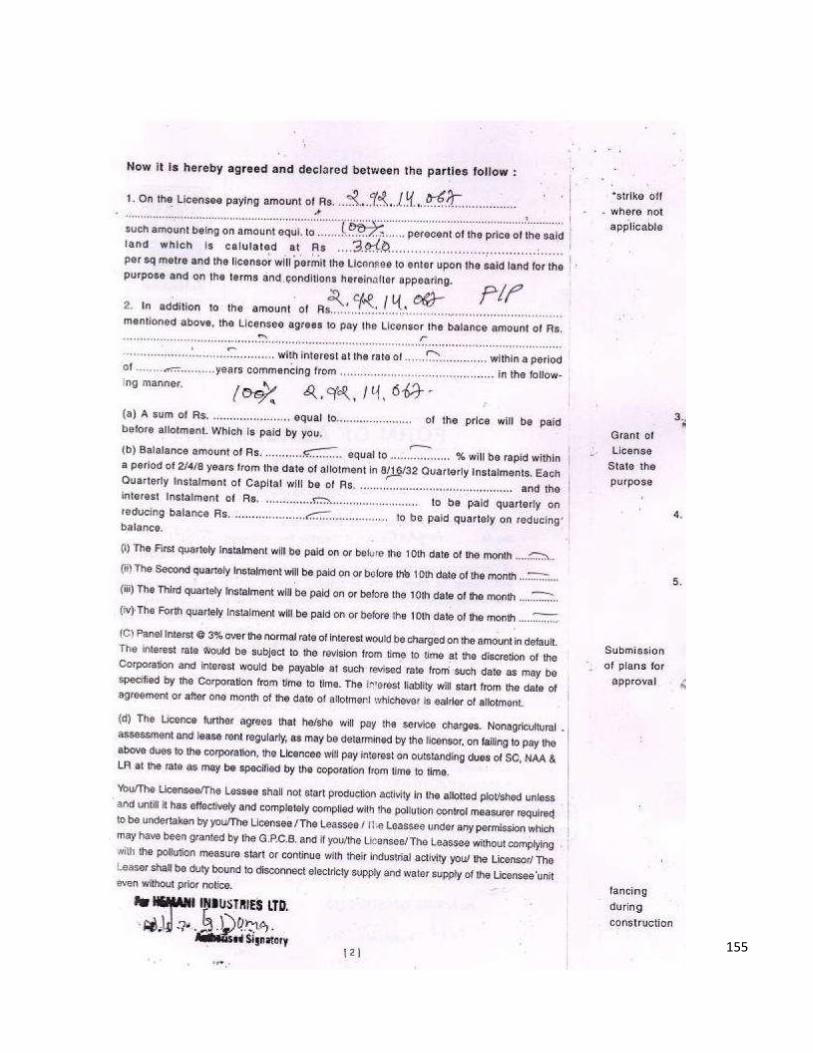
155
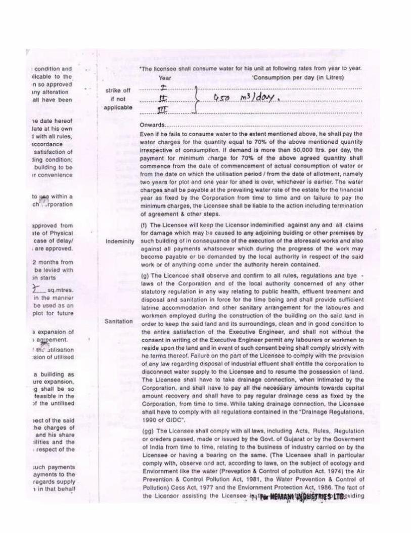
156
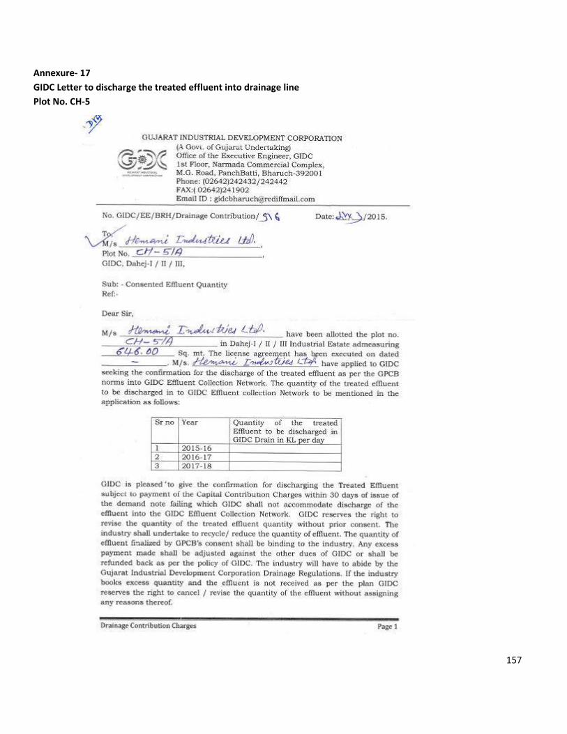
157
Annexure- 17
GIDC Letter to discharge the treated effluent into drainage line
Plot No. CH-5
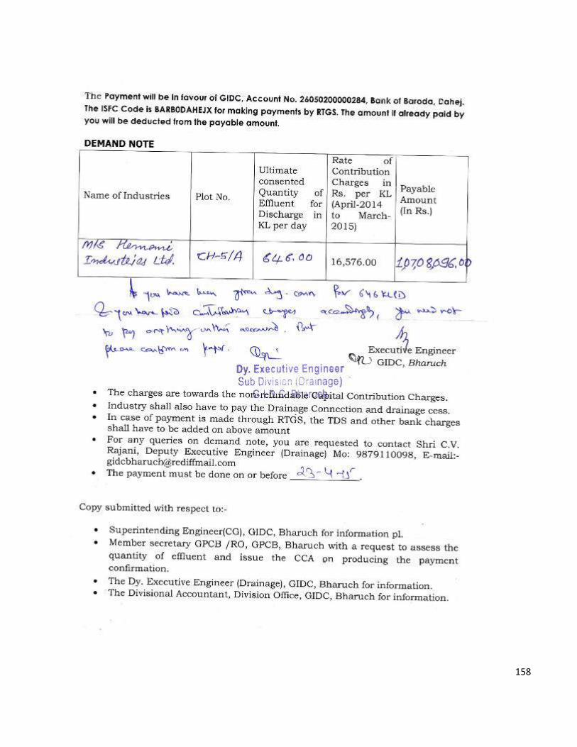
158
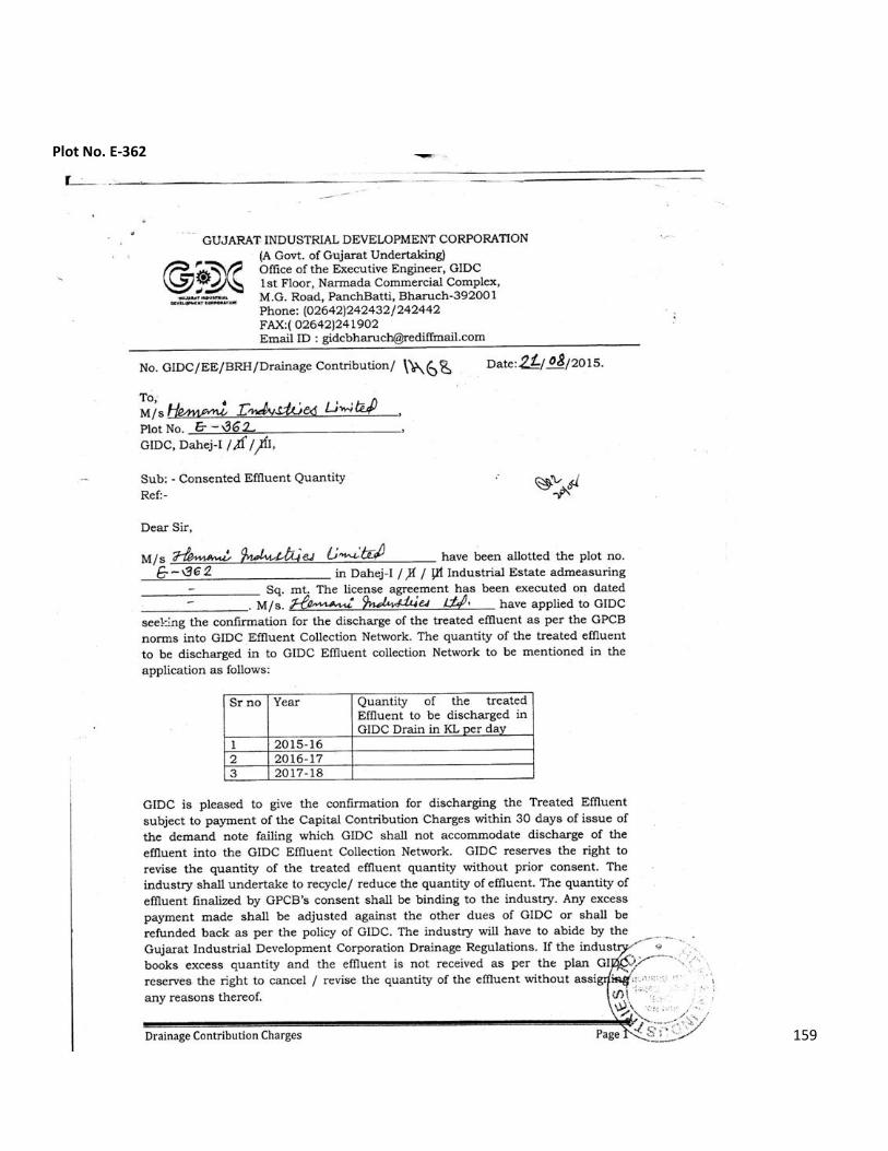
159
Plot No. E-362
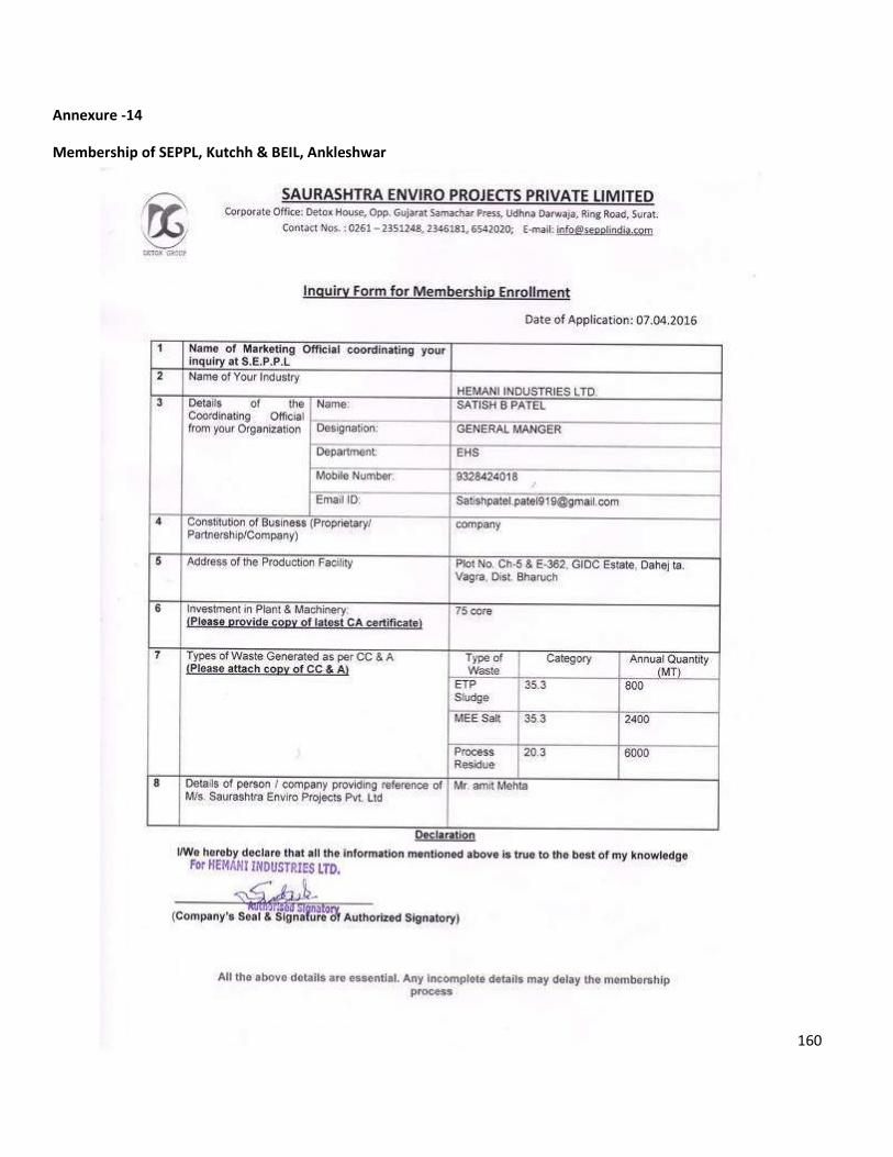
160
Annexure -14
Membership of SEPPL, Kutchh & BEIL, Ankleshwar
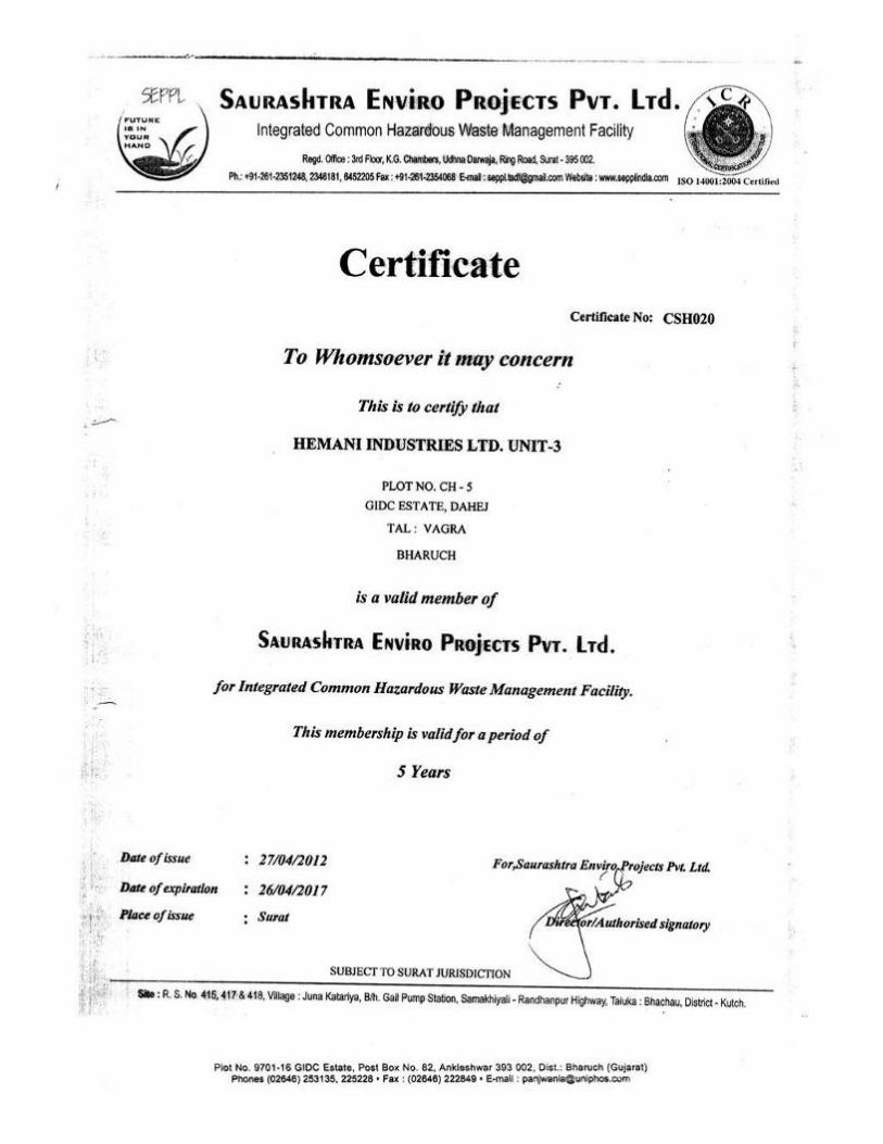
161
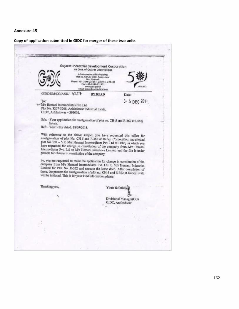
162
Annexure-15
Copy of application submitted in GIDC for merger of these two units
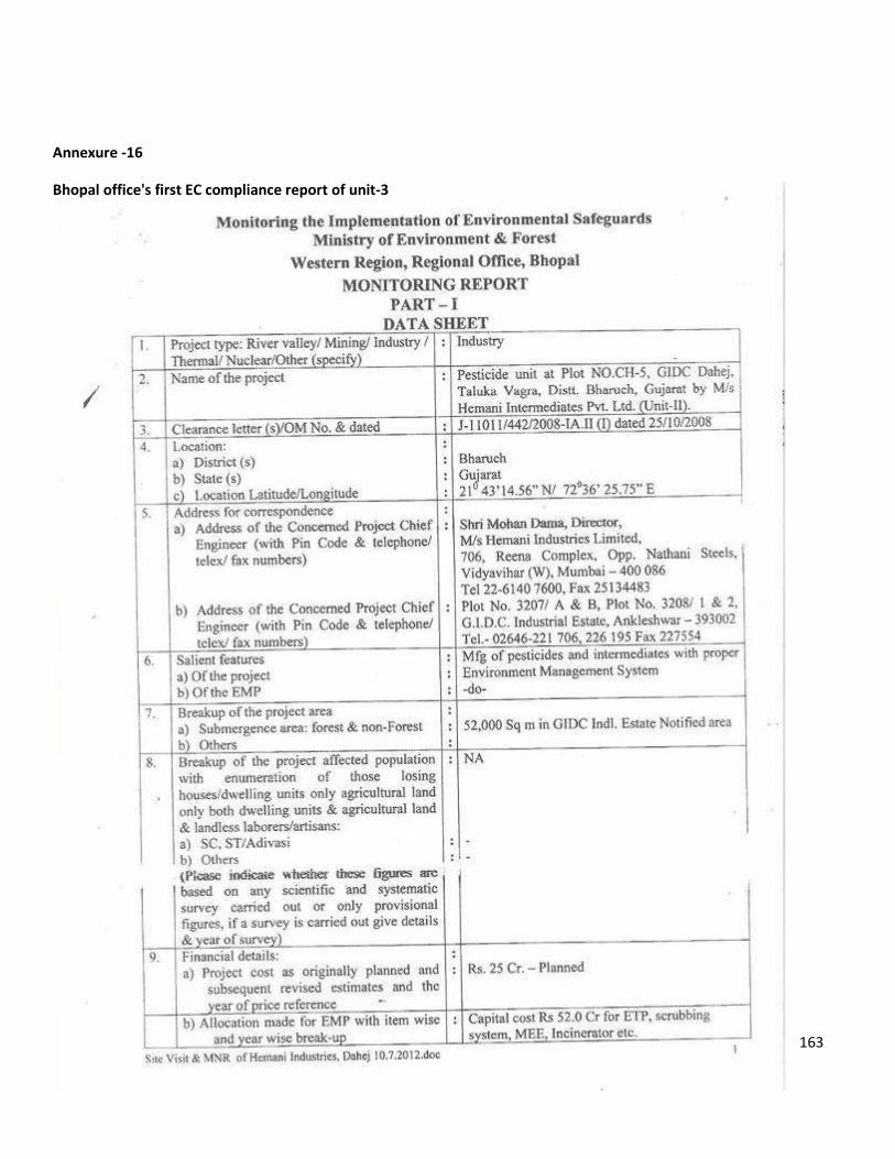
163
Annexure -16
Bhopal office's first EC compliance report of unit-3
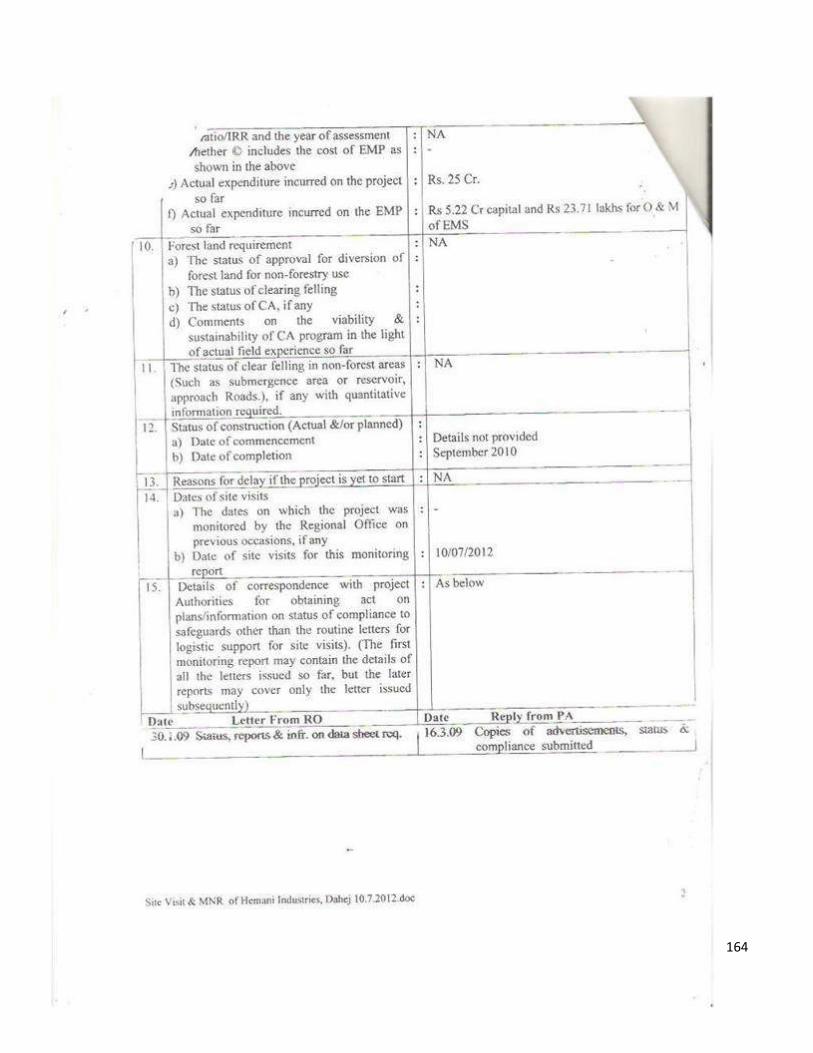
164
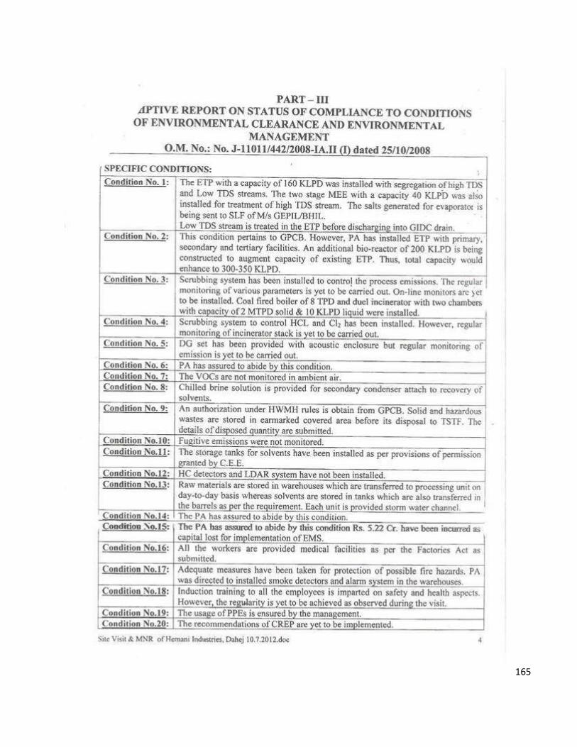
165
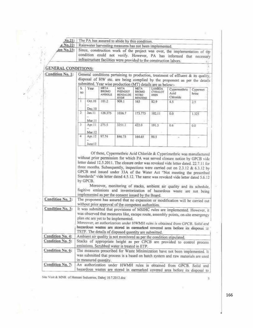
166
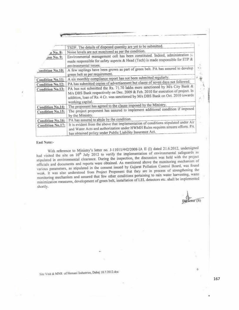
167
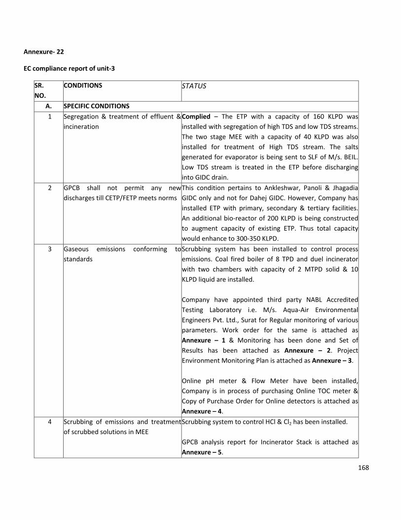
168
Annexure- 22
EC compliance report of unit-3
SR.
NO.
CONDITIONS STATUS
A. SPECIFIC CONDITIONS
1 Segregation & treatment of effluent &
incineration
Complied – The ETP with a capacity of 160 KLPD was
installed with segregation of high TDS and low TDS streams.
The two stage MEE with a capacity of 40 KLPD was also
installed for treatment of High TDS stream. The salts
generated for evaporator is being sent to SLF of M/s. BEIL.
Low TDS stream is treated in the ETP before discharging
into GIDC drain.
2 GPCB shall not permit any new
discharges till CETP/FETP meets norms
This condition pertains to Ankleshwar, Panoli & Jhagadia
GIDC only and not for Dahej GIDC. However, Company has
installed ETP with primary, secondary & tertiary facilities.
An additional bio-reactor of 200 KLPD is being constructed
to augment capacity of existing ETP. Thus total capacity
would enhance to 300-350 KLPD.
3 Gaseous emissions conforming to
standards
Scrubbing system has been installed to control process
emissions. Coal fired boiler of 8 TPD and duel incinerator
with two chambers with capacity of 2 MTPD solid & 10
KLPD liquid are installed.
Company have appointed third party NABL Accredited
Testing Laboratory i.e. M/s. Aqua-Air Environmental
Engineers Pvt. Ltd., Surat for Regular monitoring of various
parameters. Work order for the same is attached as
Annexure – 1 & Monitoring has been done and Set of
Results has been attached as Annexure – 2. Project
Environment Monitoring Plan is attached as Annexure – 3.
Online pH meter & Flow Meter have been installed,
Company is in process of purchasing Online TOC meter &
Copy of Purchase Order for Online detectors is attached as
Annexure – 4.
4 Scrubbing of emissions and treatment
of scrubbed solutions in MEE
Scrubbing system to control HCl & Cl2 has been installed.
GPCB analysis report for Incinerator Stack is attached as
Annexure – 5.
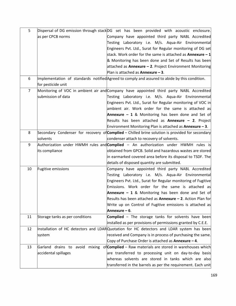
169
5 Dispersal of DG emission through stack
as per CPCB norms
DG set has been provided with acoustic enclosure.
Company have appointed third party NABL Accredited
Testing Laboratory i.e. M/s. Aqua-Air Environmental
Engineers Pvt. Ltd., Surat for Regular monitoring of DG set
stack. Work order for the same is attached as Annexure – 1
& Monitoring has been done and Set of Results has been
attached as Annexure – 2. Project Environment Monitoring
Plan is attached as Annexure – 3.
6 Implementation of standards notified
for pesticide unit
Agreed to comply and assured to abide by this condition.
7 Monitoring of VOC in ambient air and
submission of data
Company have appointed third party NABL Accredited
Testing Laboratory i.e. M/s. Aqua-Air Environmental
Engineers Pvt. Ltd., Surat for Regular monitoring of VOC in
ambient air. Work order for the same is attached as
Annexure – 1 & Monitoring has been done and Set of
Results has been attached as Annexure – 2. Project
Environment Monitoring Plan is attached as Annexure – 3.
8 Secondary Condenser for recovery of
solvents
Complied – Chilled brine solution is provided for secondary
condenser attach to recovery of solvents.
9 Authorization under HWMH rules and
its compliance
Complied – An authorization under HWMH rules is
obtained from GPCB. Solid and hazardous wastes are stored
in earmarked covered area before its disposal to TSDF. The
details of disposed quantity are submitted.
10 Fugitive emissions Company have appointed third party NABL Accredited
Testing Laboratory i.e. M/s. Aqua-Air Environmental
Engineers Pvt. Ltd., Surat for Regular monitoring of Fugitive
Emissions. Work order for the same is attached as
Annexure – 1 & Monitoring has been done and Set of
Results has been attached as Annexure – 2. Action Plan for
Write up on Control of Fugitive emissions is attached as
Annexure – 6.
11 Storage tanks as per conditions Complied – The storage tanks for solvents have been
installed as per provisions of permissions granted by C.E.E.
12 Installation of HC detectors and LDAR
system
Quotation for HC detectors and LDAR system has been
received and Company is in process of purchasing the same.
Copy of Purchase Order is attached as Annexure – 4.
13 Garland drains to avoid mixing of
accidental spillages
Complied – Raw materials are stored in warehouses which
are transferred to processing unit on day-to-day basis
whereas solvents are stored in tanks which are also
transferred in the barrels as per the requirement. Each unit
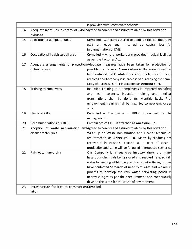
170
is provided with storm water channel.
14 Adequate measures to control of Odour
nuisance
Agreed to comply and assured to abide by this condition.
15 Allocation of adequate funds Complied - Company assured to abide by this condition. Rs
5.22 Cr. Have been incurred as capital lost for
implementation of EMS.
16 Occupational health surveillance Complied – All the workers are provided medical facilities
as per the Factories Act.
17 Adequate arrangements for protection
of fire hazards
Adequate measures have been taken for protection of
possible fire hazards. Alarm system in the warehouses has
been installed and Quotation for smoke detectors has been
received and Company is in process of purchasing the same.
Copy of Purchase Order is attached as Annexure – 4.
18 Training to employees Induction Training to all employees is imparted on safety
and health aspects. Induction training and medical
examinations shall be done on Monthly basis. Pre-
employment training shall be imparted to new employees
also.
19 Usage of PPEs Complied – The usage of PPEs is ensured by the
management.
20 Recommendations of CREP Compliance of CREP is attached as Annexure – 7.
21 Adoption of waste minimization and
cleaner techniques
Agreed to comply and assured to abide by this condition.
Write up on Waste minimization and Cleaner techniques
are attached as Annexure – 8. Many by-products are
recovered in existing scenario as a part of cleaner
production and same will be followed in proposed scenario.
22 Rain water harvesting Our Company is a pesticide industry there are many
hazardous chemicals being stored and reacted here, so rain
water harvesting within the premises is not suitable, but we
have contacted Sarpanch of near by villages and we are in
process to develop the rain water harvesting ponds in
nearby villages as per their requirement and continuously
develop the same for the cause of environment.
23 Infrastructure facilities to construction
labor
Complied
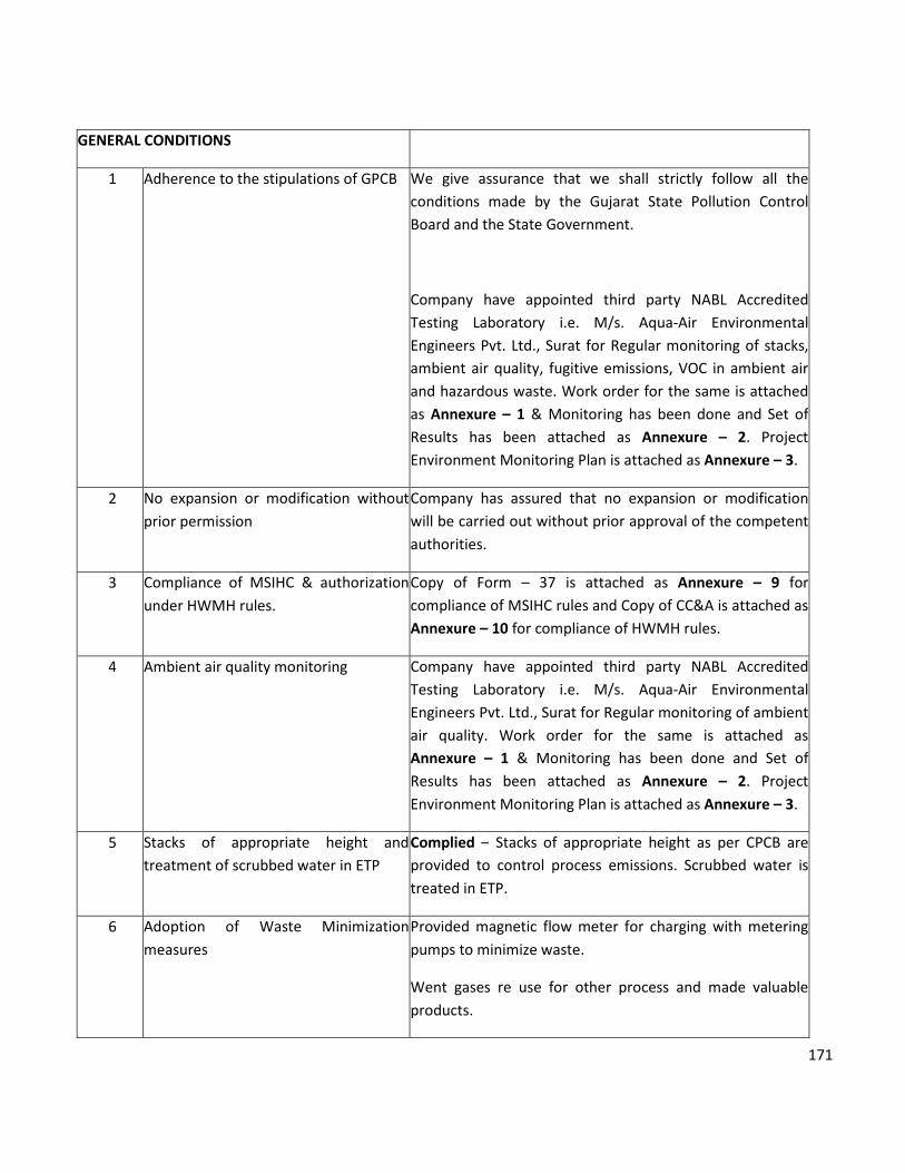
171
GENERAL CONDITIONS
1 Adherence to the stipulations of GPCB We give assurance that we shall strictly follow all the
conditions made by the Gujarat State Pollution Control
Board and the State Government.
Company have appointed third party NABL Accredited
Testing Laboratory i.e. M/s. Aqua-Air Environmental
Engineers Pvt. Ltd., Surat for Regular monitoring of stacks,
ambient air quality, fugitive emissions, VOC in ambient air
and hazardous waste. Work order for the same is attached
as Annexure – 1 & Monitoring has been done and Set of
Results has been attached as Annexure – 2. Project
Environment Monitoring Plan is attached as Annexure – 3.
2 No expansion or modification without
prior permission
Company has assured that no expansion or modification
will be carried out without prior approval of the competent
authorities.
3 Compliance of MSIHC & authorization
under HWMH rules.
Copy of Form – 37 is attached as Annexure – 9 for
compliance of MSIHC rules and Copy of CC&A is attached as
Annexure – 10 for compliance of HWMH rules.
4 Ambient air quality monitoring Company have appointed third party NABL Accredited
Testing Laboratory i.e. M/s. Aqua-Air Environmental
Engineers Pvt. Ltd., Surat for Regular monitoring of ambient
air quality. Work order for the same is attached as
Annexure – 1 & Monitoring has been done and Set of
Results has been attached as Annexure – 2. Project
Environment Monitoring Plan is attached as Annexure – 3.
5 Stacks of appropriate height and
treatment of scrubbed water in ETP
Complied – Stacks of appropriate height as per CPCB are
provided to control process emissions. Scrubbed water is
treated in ETP.
6 Adoption of Waste Minimization
measures
Provided magnetic flow meter for charging with metering
pumps to minimize waste.
Went gases re use for other process and made valuable
products.
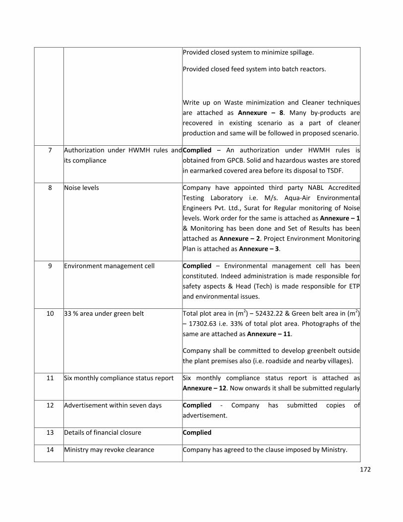
172
Provided closed system to minimize spillage.
Provided closed feed system into batch reactors.
Write up on Waste minimization and Cleaner techniques
are attached as Annexure – 8. Many by-products are
recovered in existing scenario as a part of cleaner
production and same will be followed in proposed scenario.
7 Authorization under HWMH rules and
its compliance
Complied – An authorization under HWMH rules is
obtained from GPCB. Solid and hazardous wastes are stored
in earmarked covered area before its disposal to TSDF.
8 Noise levels Company have appointed third party NABL Accredited
Testing Laboratory i.e. M/s. Aqua-Air Environmental
Engineers Pvt. Ltd., Surat for Regular monitoring of Noise
levels. Work order for the same is attached as Annexure – 1
& Monitoring has been done and Set of Results has been
attached as Annexure – 2. Project Environment Monitoring
Plan is attached as Annexure – 3.
9 Environment management cell
Complied – Environmental management cell has been
constituted. Indeed administration is made responsible for
safety aspects & Head (Tech) is made responsible for ETP
and environmental issues.
10 33 % area under green belt Total plot area in (m2) – 52432.22 & Green belt area in (m2)
– 17302.63 i.e. 33% of total plot area. Photographs of the
same are attached as Annexure – 11.
Company shall be committed to develop greenbelt outside
the plant premises also (i.e. roadside and nearby villages).
11 Six monthly compliance status report Six monthly compliance status report is attached as
Annexure – 12. Now onwards it shall be submitted regularly
12 Advertisement within seven days Complied - Company has submitted copies of
advertisement.
13 Details of financial closure Complied
14 Ministry may revoke clearance Company has agreed to the clause imposed by Ministry.
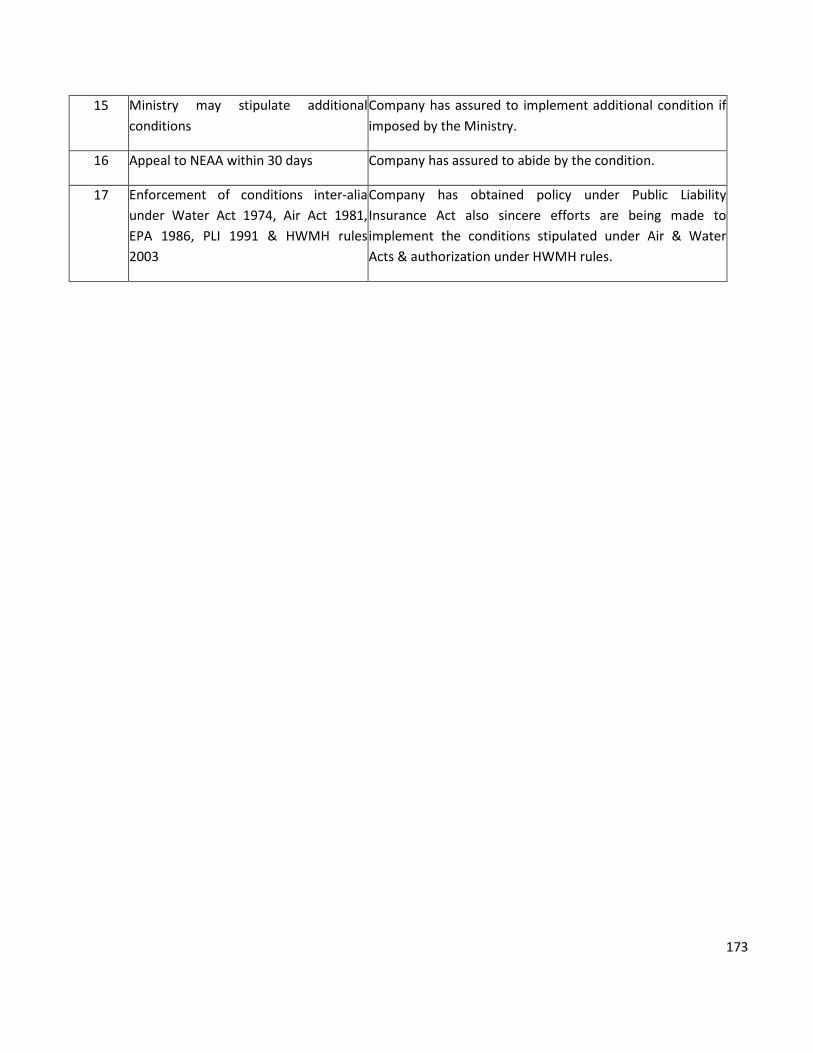
173
15 Ministry may stipulate additional
conditions
Company has assured to implement additional condition if
imposed by the Ministry.
16 Appeal to NEAA within 30 days Company has assured to abide by the condition.
17 Enforcement of conditions inter-alia
under Water Act 1974, Air Act 1981,
EPA 1986, PLI 1991 & HWMH rules
2003
Company has obtained policy under Public Liability
Insurance Act also sincere efforts are being made to
implement the conditions stipulated under Air & Water
Acts & authorization under HWMH rules.