property damage! retain instructions for future reference ... operating instructions and parts...
TRANSCRIPT

Welder / Generator
Table of ContentsDescription . . . . . . . . . . . . . . . . . . . . . .1
Unpacking . . . . . . . . . . . . . . . . . . . . . . .1
Safety Guidelines . . . . . . . . . . . . . . . . .1
Specifications. . . . . . . . . . . . . . . . . . . . .1
General Safety Information . . . . . . 2 - 4
Glossary of Terms . . . . . . . . . . . . . . . . .5
Pre-operation . . . . . . . . . . . . . . . . . 6 - 7
Operation . . . . . . . . . . . . . . . . . . . . 7 - 9
Maintenance . . . . . . . . . . . . . . . . . . . . .9
Storage . . . . . . . . . . . . . . . . . . . . . . . . .9
Welding Guidelines. . . . . . . . . . . 10 - 12
Troubleshooting Chart . . . . . . . . 13 - 14 General . . . . . . . . . . . . . . . . . . . . . .13 Generator . . . . . . . . . . . . . . . . . . . .13 Welder . . . . . . . . . . . . . . . . . . . . . .14 Welds . . . . . . . . . . . . . . . . . . . . . . .14
Wiring Diagram. . . . . . . . . . . . . . . . . .15
Welder / Generator Assembly. . . 16 - 17
Alternator Assembly . . . . . . . . . . 18 - 19
Warranty . . . . . . . . . . . . . . . . . . . . . . .20
DescriptionThis welder / generator is powered by an air-cooled four cycle engine and designed to run at maximum RPM and give a continuous wattage as rated. A low-oil level shutoff is provided to protect the engine. The alternator is thermostatically protected. To operate this unit as a generator or welder, set the switch on the front panel accordingly.
UnpackingAfter unpacking the welder / generator, inspect carefully for any damage that may have occurred during transit. Make sure to tighten fittings, bolts, etc., before putting unit into service. Report any missing items by calling 1-800-543-6400.
Safety GuidelinesThis manual contains information that is very important to know and understand. This information is provided for SAFETY and to PREVENT EQUIPMENT PROBLEMS. To help recognize this information, observe the following symbols. Danger indicates an
imminently hazardous situation which, if not avoided, WILL result in death or serious injury.
Warning indicates a potentially
hazardous situation which, if not avoided, COULD result in death or serious injury.
Caution indicates a potentially
hazardous situation which, if not avoided, MAY result in minor or moderate injury.
Notice indicates important
information, that if not followed, may cause damage to equipment.
NOTE: Information that requires special attention.
SpecificationsENGINEEngine Type . . . . .270cc, 4 stroke OHVNet Power . . . . . . . . . . . . . . . . . . . . 6.0Ignition System . . Transistor MagnetoStart Mode . . . . . . . . . . . . . . . . ManualFuel Capacity . . . . . . . . . . . 1.4 gallonsOil Capacity . . . . . . . 38.4 fluid ounces
GENERATORType . . . . . . 2 pole, brushless rotatingPhase . . . . . . . . . . . . . . . . . . . . . SingleContinuous Power Rating (KVA) . . . . . . . . . . . . . . . . . . 4.5Rated Voltage (V) . . . . . . . . . 120 / 240
WELDERMax Open Circuit Voltage (V). . . . 62.5Rated Voltage (V) . . . . . . . . . . . . . 25.6Rated Current (A) . . . . . . . . . . . . . .140Max No Load Speed (r/min) . . . . .3850Current Control Range (A) . . . 60 - 140Rated Duty Cycle (%) . . . . . . . . . . . .35Electrode Diameter (mm) . . . . 2.4 - 3.2
IN954000AV 8/08
QUALI
TYASSURANCEPROGRAMNeedAssistance?
Call Us First!1-800-543-6400
Please read and save these instructions. Read carefully before attempting to assemble, install, operate or maintain the product described. Protect yourself and others by observing all safety information. Failure to comply with instructions could result in personal injury and/or property damage! Retain instructions for future reference.
For parts, product & service informationvisit www.chpower.com or call 1-800-543-6400
REMINDER: Keep your dated proof of purchase for warranty purposes! Attach it to this manual or file it for safekeeping.
© 2008 Campbell Hausfeld/Scott Fetzer
Operating Instructions and Parts Manual GW4500
See Warranty on page 20 for important information about commercial use of this product.

2
www.chpower.com
Operating Instructions and Parts Manual
General Safety Information
CALIFORNIA PROPOSITION 65 The cables on this
product may contain chemicals, including lead, known to the State of California to cause cancer and birth defects or other reproductive harm. Wash hands after handling. The engine exhaust
from this product contains chemicals known to the State of California to cause cancer, birth defects, or other reproductive harm. This product, when
used for welding, produces fumes or gases which contain chemicals known to the State of California to cause birth defects (or other reproductive harm) and, in some cases, cancer (California Health & Safety Code Section 25249.5 et seq.)
You can create dust when you cut, sand, drill or grind materials such as wood, paint, metal, concrete, cement, or other masonry. This dust often contains chemicals known to cause cancer, birth defects, or other reproductive harm. Wear protective gear.
EMISSIONS Engines that are
certifi ed to comply with U.S. EPA emission regulations for SORE (Small Off Road Equipment), are certifi ed to operate on regular unleaded gasoline, and may include the following emission control systems: (EM) Engine Modifi cations and (TWC) Three-Way Catalyst (if so equipped).
Using a generator indoors CAN KILL
YOU IN MINUTES. Generator exhaust contains carbon monoxide. This is a poison you cannot see or smell.
• NEVER use inside a house or garage, EVEN IF doors and windows are open.
• Only use OUTSIDE and far away from windows, doors and vents.
GENERAL SAFETY
• Before starting or servicing any welder / generator, read and understand all instructions. Failure to follow safety precautions or instructions can cause equipment damage and or serious personal injury or death. Engine instructions for these units are contained in a separate manual. Retain all manuals for future reference.
Never operate
this welder / generator in an explosive or flammable atmosphere or poorly ventilated area.
• Never use this welder / generator for any application other than that specified by the manufacturer. Never operate this welder /generator under conditions not approved by the manufacturer. Never attempt to modify this welder / generator to perform in any manner not intended by the manufacturer.
• For maintenance and repairs, use only products and parts recommended by the manufacturer.
• Be sure that the welder / generator is properly grounded to an external ground path prior to operation. Refer to the section entitled "Grounding Instructions" for proper grounding procedures.
• Be sure that the welder / generator is operated only by persons who have read and understand these instructions.
• Be sure that the welder / generator is placed on a flat level surface prior to and during operation. The welder / generator must not slide or shift during operation.
• Keep all persons away from the welder / generator during operation.
• Do not allow persons wearing loose clothing or jewelry to start or operate the welder / generator. Loose clothing or jewelry may
become entangled in moving components, causing equipment damage and or personal injury.
• Keep all persons away from parts that move or become hot during operation.
• Be sure all powered devices are shut off prior to connecting them to the welder / generator.
• Keep the welder / generator clean and well maintained at all times.
• Be sure that all tools and appliances are in good repair and are properly grounded. Use devices that have three prong power cords. If an extension cord is used, be sure that it has three prongs for proper grounding.
Do not operate this welder / generator
on wet surfaces or in the rain.
Shut off the engine and disconnect the
spark plug wire before performing any service or maintenance to the unit.
• Use only unleaded fuel. Do not refill the fuel tank while the engine is running. Use precautions to prevent fuel spillage during refills. Be sure the fuel tank cap is securely in place before starting the engine. Clean up any spilled fuel before starting the engine. Allow engine to cool for at least two minutes before refueling. Do not add fuel while smoking or if unit is near any sparks or open flames. Do not overfill tank - allow room for fuel to expand. Always keep nozzle in contact with tank during fueling.
• This welder / generator may be used for emergency stand-by service. In such cases, a manual transfer switch must be installed between the electric utilities meter and the electrical distribution box. This switch should be installed by a licensed electrician.
Never mix oil with gasoline for this
engine. This is a four cycle engine designed to run on pure gasoline. Oil is used for engine lubrication purposes only.
MANUAL

3
www.chpower.com
GW4500
General Safety Information (Continued) Always
keep a fire extinguisher accessible while performing arc welding operations.
• All installation, maintenance, repair and operation of this equipment should be performed by qualified persons only in accordance with national, state, and local codes.
Improper use of
electric arc welders can cause electric shock, injury, and death! Take all precautions described in this manual to reduce the possibility of electric shock.
• Verify that all components of the arc welder are clean and in good condition prior to operating the welder. Be sure that the insulation on all cables, electrode holders, and power cords is not damaged. Always repair or replace damaged components before operating the welder. Always keep welder panels, shields, etc. in place when operating the welder.
• Always wear dry protective clothing and welding gloves, and insulated footwear.
• Always operate the welder in a clean, dry, well ventilated area. Do not operate the welder in humid, wet, rainy, or poorly ventilated areas.
• Be sure that the work piece is properly supported and grounded prior to beginning any electric arc welding operation.
• Coiled welding cable should be spread out before use to avoid overheating and damage to insulation.
Never immerse the electrode or
electrode holder in water. If the welder becomes wet for any reason, be absolutely certain that it is completely clean and dry prior to attempting use!
• Always shut the equipment off prior to moving the unit.
• Always attach the work lead first.
• Verify that the work piece is securely grounded.
• Always shut off electric arc welding equipment when not in use and remove the electrode from the holder.
• Never allow any part of the body to touch the electrode and ground or grounded work piece at the same time.
• Awkward welding conditions and positions can be electrically hazardous. When crouching, kneeling or at elevations, be sure to insulate all conductive parts, wear appropriate protective clothing, and take precautions to prevent injury from falls.
• Never attempt to use this equipment at current settings or duty cycles higher than those specified on the equipment labels.
• Never use an electric arc welder to thaw frozen pipes.
Flying sparks
and hot metal can cause injury. As welds cool, slag can be thrown off. Take all precautions described in this manual to reduce the possibility of injury from flying sparks and hot metal.
• Wear ANSI approved face shield or safety glasses with side shield protection when chipping or grinding metal parts.
• Wear ear plugs when welding overhead to prevent spatter or slag from falling into ears.
Electric arc
welding operations produce intense light and heat and ultraviolet (UV) rays. This intense light and UV rays can cause injury to eyes and skin. Take all precautions described in this manual to reduce the possibility of injury to eyes and skin.
• All persons operating this equipment or in the area while equipment is in use must wear protective welding gear including: welding helmet or shield with at least shade 10, flame resistant clothing, leather welding gloves, and full foot protection.
Never look at arc welding operations
without eye protection as described above. Never use a shade filter lens that is cracked, broken, or rated below number 10. Warn others in the area not to look at the arc.
Electric arc
welding operations cause sparks and heat metal to temperatures that can cause severe burns! Use protective gloves and clothing when performing any metal working operation. Take all precautions described in this manual to reduce the possibility of skin and clothing burns.
• Make sure that all persons in the welding area are protected from heat, sparks, and ultraviolet rays. Use additional face shields and flame resistant barriers as needed.
• Never touch work pieces until completely cooled.
Heat and sparks
produced during electric arc welding and other metal working operations can ignite flammable and explosive materials! Take all precautions described in this manual to reduce the possibility of flames and explosions.
• Remove all flammable materials within 35 feet (10.7 meters) of welding arc. If removal is not possible, tightly cover flammable materials with fire proof covers.
• Take precautions to be sure that flying sparks and heat do not cause flames in hidden areas, cracks, behind bulkheads, etc.
• Do not use any part of the unit as a work surface.

4
www.chpower.com
Operating Instructions and Parts Manual
General Safety Information (Continued) Fire
hazard! Do not weld on containers or pipes that contain or have contained flammable materials or gaseous or liquid combustibles.
Arc welding
closed cylinders or containers such as tanks or drums can cause explosion if not properly vented! Verify that any cylinder or container to be welded has an adequate ventilation hole, so that expanding gases can be released.
Do not breathe
fumes that are produced by the arc welding operation. These fumes are dangerous. If the welding area cannot be adequately ventilated, be sure to use an air-supplied respirator.
• Keep the head and face out of the welding fumes.
• Do not perform electric arc welding operations on metals that are galvanized or cadmium plated, or contain zinc, mercury, or beryllium without completing the following precautions:
a. Remove the coating from the base metal.
b. Make sure that the welding area is well ventilated.
c. Use an air-supplied respirator.Extremely toxic fumes are created when these metals are heated.
The
electromagnetic field that is generated during arc welding may interfere with the operation of various electrical and electronic devices such as cardiac pacemakers. Persons using such devices should consult with their physician prior to performing any electric arc welding operations.
• Route the electrode and work cables together and secure with tape when possible.
• Never wrap arc welder cables around the body.
• Always position the electrode and work leads so that they are on the same side of the body.
• Exposure to electromagnetic fields during welding may have other health effects which are not known.
Always be sure that the welding area
is secure and free of hazards (sparks, flames, glowing metal or slag) prior to leaving. Be sure that the equipment is turned off and electrode is removed. Be sure that cables are loosely coiled and out of the way. Be sure that all metal and slag has cooled.
ADDITIONAL SAFETY STANDARDS
ANSI Standard Z49.1 from American Welding Society, 550 N.W. LeJune Rd. Miami, FL 33126
Safety and Health Standards
OSHA 29 CFR 1910, from Superintendent of Documents, U.S. Government Printing Office, Washington, D.C. 20402
National Electrical Code
NFPA Standard 70, from National Fire Protection Association, Batterymarch Park, Quincy, MA 02269
Safe Handling of Compressed Gases in Cylinders
CGA Pamphlet P-1, from Compressed Gas Association, 1235 Jefferson Davis Highway, Suite 501, Arlington, VA 22202
Code for Safety in Welding and Cutting
CSA Standard W117.2, from Canadian Standards Association, Standards Sales, 178 Rexdale Boulevard, Rexdale, Ontario, Canada M9W 1R3
Cutting And Welding Processes
NFPA Standard 51B, from National Fire Protection Association, Batterymarch Park, Quicy, MA 02269
Safe Practices For Occupational And Educational Eye And Face Protection
ANSI Standard Z87.1, from American National Standards Institute, 1430 Broadway, New York, NY 10018Refer to the Material Safety Data Sheets and the manufacturers instructions for metals, electrodes, coatings and cleaners.
5
www.chpower.com
GW4500
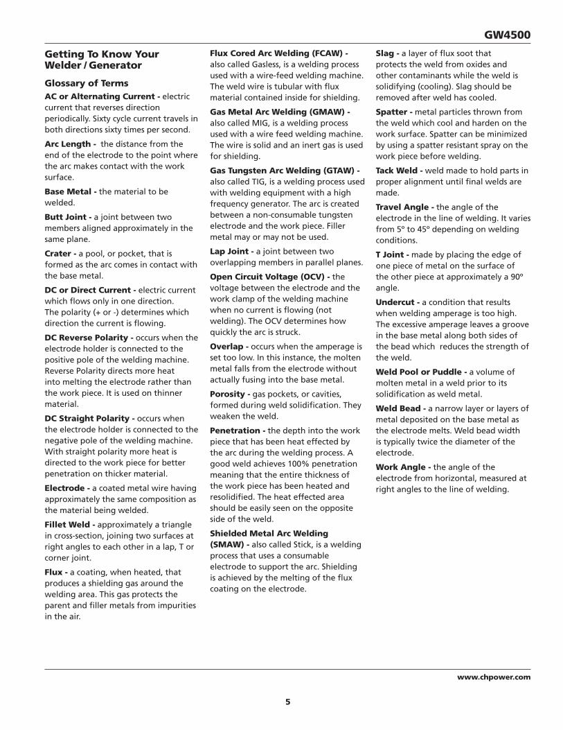
Getting To Know Your Welder / Generator
Glossary of TermsAC or Alternating Current - electric current that reverses direction periodically. Sixty cycle current travels in both directions sixty times per second.
Arc Length - the distance from the end of the electrode to the point where the arc makes contact with the work surface.
Base Metal - the material to be welded.
Butt Joint - a joint between two members aligned approximately in the same plane.
Crater - a pool, or pocket, that is formed as the arc comes in contact with the base metal.
DC or Direct Current - electric current which flows only in one direction. The polarity (+ or -) determines which direction the current is flowing.
DC Reverse Polarity - occurs when the electrode holder is connected to the positive pole of the welding machine. Reverse Polarity directs more heat into melting the electrode rather than the work piece. It is used on thinner material.
DC Straight Polarity - occurs when the electrode holder is connected to the negative pole of the welding machine. With straight polarity more heat is directed to the work piece for better penetration on thicker material.
Electrode - a coated metal wire having approximately the same composition as the material being welded.
Fillet Weld - approximately a triangle in cross-section, joining two surfaces at right angles to each other in a lap, T or corner joint.
Flux - a coating, when heated, that produces a shielding gas around the welding area. This gas protects the parent and filler metals from impurities in the air.
Slag - a layer of flux soot that protects the weld from oxides and other contaminants while the weld is solidifying (cooling). Slag should be removed after weld has cooled.
Spatter - metal particles thrown from the weld which cool and harden on the work surface. Spatter can be minimized by using a spatter resistant spray on the work piece before welding.
Tack Weld - weld made to hold parts in proper alignment until final welds are made.
Travel Angle - the angle of the electrode in the line of welding. It varies from 5º to 45º depending on welding conditions.
T Joint - made by placing the edge of one piece of metal on the surface of the other piece at approximately a 90º angle.
Undercut - a condition that results when welding amperage is too high. The excessive amperage leaves a groove in the base metal along both sides of the bead which reduces the strength of the weld.
Weld Pool or Puddle - a volume of molten metal in a weld prior to its solidification as weld metal.
Weld Bead - a narrow layer or layers of metal deposited on the base metal as the electrode melts. Weld bead width is typically twice the diameter of the electrode.
Work Angle - the angle of the electrode from horizontal, measured at right angles to the line of welding.
Flux Cored Arc Welding (FCAW) - also called Gasless, is a welding process used with a wire-feed welding machine. The weld wire is tubular with flux material contained inside for shielding.
Gas Metal Arc Welding (GMAW) - also called MIG, is a welding process used with a wire feed welding machine. The wire is solid and an inert gas is used for shielding.
Gas Tungsten Arc Welding (GTAW) - also called TIG, is a welding process used with welding equipment with a high frequency generator. The arc is created between a non-consumable tungsten electrode and the work piece. Filler metal may or may not be used.
Lap Joint - a joint between two overlapping members in parallel planes.
Open Circuit Voltage (OCV) - the voltage between the electrode and the work clamp of the welding machine when no current is flowing (not welding). The OCV determines how quickly the arc is struck.
Overlap - occurs when the amperage is set too low. In this instance, the molten metal falls from the electrode without actually fusing into the base metal.
Porosity - gas pockets, or cavities, formed during weld solidification. They weaken the weld.
Penetration - the depth into the work piece that has been heat effected by the arc during the welding process. A good weld achieves 100% penetration meaning that the entire thickness of the work piece has been heated and resolidified. The heat effected area should be easily seen on the opposite side of the weld.
Shielded Metal Arc Welding (SMAW) - also called Stick, is a welding process that uses a consumable electrode to support the arc. Shielding is achieved by the melting of the flux coating on the electrode.

6
www.chpower.com
Operating Instructions and Parts Manual
GROUNDING1. Use the ground terminal and wing
nut on the welder / generator frame to connect the unit to a suitable ground source. Securely fasten the end terminal of the ground wire to the ground terminal on the welder / generators frame. Tighten the washer and wing nut on top of the ground wire end terminal.
2. The ground wire should be made of #8 gauge wire. Do not use wire with a higher gauge number. Higher gauge numbers indicate thinner wire, which may not provide an adequate ground path.
3. The other end of the ground wire must be securely fastened to an approved ground source.
The following are ground sources approved by the National Electric Code. Other ground sources may be acceptable. Refer to the National Electric Code and local regulations for further ground source information. If not sure of regulations or procedures, obtain assistance from a qualified (licensed or certified) electrical technician.
a. An underground water pipe at least ten feet in length
b. A non-corrosive underground pipe at least eight feet in length and 3/4 inch diameter
c. A steel or iron underground rod at least eight feet in length and 5/8 inch diameter
d. A non-ferrous rod at least eight feet in length, 1/2 inch in diameter, and approved for grounding purposes
Any rod or pipe used for grounding must be driven to eight feet deep or buried in the deepest possible trench.
STARTING1. Remove all electrical loads from the
welder / generators.
2. Move fuel shut-off lever as far as possible to the right to enable fuel flow.
3. Rotate the engine switch to the ON position.
4. Adjust the choke lever as follows:
a. For cold engine, move the choke lever as far as possible to the left, choke fully ON, position.
b. For warm / hot engine, move the choke lever midway between the choke and run positions.
5. Pull the starter rope with a brisk, smooth motion.NOTE: Some models may be equipped with an electric starter. For models equipped with an electric starter, turn the key.
6. After each start up, allow the engine to run for 2-3 minutes with no load.
7. As the engine warms up and stabilizes, adjust the choke lever to the right, until the lever is positioned as far as possible to the right.
Engine speed is preset to provide
proper output voltage. Never attempt to modify or adjust engine speed or output voltage.
ENGINE BREAK-INAfter initial start-up, the engine should be broken in according to the manufacturer's instructions. Refer to the engine manual for the proper break-in procedure.
SHUT-OFF1. Shut off and remove all electrical
load devices from the welder / generator.
2. Allow the engine to run for 2-3 minutes with no electrical loads.
3. Rotate the engine switch to the OFF position.
4. Verify that the welder / generator has completely stopped.
5. Close the fuel supply valve.
6. Allow the unit to cool before installing any covers.
Pre-OperationLOCATIONSelecting the proper location can significantly increase performance, reliability and life of the arc welder.
• For best results locate the welder / generator in an environment that is clean and dry. Dust and dirt in the unit retain moisture and increase wear of moving parts.
• Store electrodes in a clean, dry location with low humidity to preserve the flux coating.
INSTRUCTIONS1. Check engine oil level. Oil is NOT
mixed with the gasoline, however adequate oil supply is necessary for proper engine lubrication. Refer to the Engine Manual for SAE, API and fill quantity specifications. Unit is shipped without oil in engine.
2. Use of a Ground Fault Interrupter (GFI) is strongly recommended. Ground Fault Interrupters can significantly reduce the possibility of injury if an electrical short occurs. In order to install a GFI, the welder / generators neutral wire must be internally grounded to the welder / generators frame, and the frame must be properly grounded to the earth.
A Ground Fault Interrupter may
not be effective if used on a welder / generators that is not grounded! Refer to the section entitled Grounding for proper steps to ground the welder / generator.
3. When installing a GFI, be sure to follow all national and local regulations. If not sure of regulations or procedures, obtain assistance from a qualified (licensed or certified) electrical technician.

7
www.chpower.com
GW4500
combination of 240 volt loads and also with 120 volt loads through the 120 volt receptacles.
The 120/240 volt twist lock receptacle, found on some welder / generators, is rated for 20 amps and may be used in any combination of 120 volt and 240 volt loads.
4. Individual receptacles should not be loaded beyond the amperage rating.
5. Total combined load through any combination of receptacle must not exceed the rated load limits of the welder / generator. Refer to the identification plate on the welder / generators for amp and wattage specifications.
6. Always shut off and remove loads before starting or shutting off the welder / generator engine.
7. When plugging multiple electrical load devices into the welder / generators receptacles, be sure to connect and activate the highest power draw item first. Allow the welder / generator engine to stabilize, then connect and activate the next highest power draw device. The smallest power draw device should be connected to the receptacle and activated last.
NOTE: Power draw can be calculated by multiplying volts and amps. The resulting number is wattage.
Never exceed the posted maximum wattage for the welder / generator or any individual receptacle. Refer to owner's manuals and product tags to determine the wattage of all electrical load devices.
If actual watt ratings are not available, the Power Usage Chart, see Table 1, may be used as a general guideline.
Remember that devices which generate heat during operation such as heaters, incandescent light bulbs, motors and hair dryers have a higher power draw than devices which generate little heat during operation such as florescent bulbs, radios, and clocks.
Long power cords and extension cords also draw additional power. Keep cords at minimum possible length.
Refer to Table 2 for maximum limits for lengths of extension cords.
8. Circuit protection is provided by a circuit breaker. The circuit breaker opens when the welder / generator load exceeds its maximum capacity or a short circuit occurs. If the circuit breaker opens, perform the following procedures to correct the problem:
a. Shut off and disconnect all electrical loads.
b. Attempt to determine the cause of the electrical problem - overloading or short circuit.
c. Do not use any devices that have short circuits. Avoid overloading the welder / generator.
d. Press the circuit breaker pushbutton to reset the circuit breaker.
Repeated cycling of the circuit breaker
indicates a problem and may cause damage to the welder / generators or load devices. Do not operate the welder / generators if repeated cycling of the circuit breaker occurs.
Pre-Operation (Continued)LOW OIL SHUTDOWNA low oil shutdown switch is provided to protect the engine and welder / generators on most extended run models. When engine oil level drops too low for proper engine operation, the low oil shutdown switch causes the engine to shut off. If oil level is low when attempting to start the welder / generators engine, the low oil level shutdown switch prevents the engine from starting. If engine does not start, check oil level.
NOTE: It is important to keep the welder / generator unit on a level surface. The oil level shutdown switch can prevent the engine from starting even if oil level is sufficient, when the welder / generators unit is placed on an uneven surface.
Generator Operation(FRONT PANEL SWITCH MUST BE SET TO GENERATOR POSITION)
LOAD DEVICES1. All load devices and extension cords
should use three prong terminals. Refer to Table 2 for extension cord and cable size requirements.
2. Allow the engine to run for 2-3 minutes before applying any electrical loads.
3. The 120 volt receptacles are rated for 20 amps and may be used in any combination of 120 volt loads and also with 240 volt loads through the 240 volt receptacles.
The 240 volt receptacles, found on some welder / generators, are rated for 20 amps and may be used in any
TABLE 1 - ESTIMATED POWER USAGE (WATTS)
LOAD DEVICE WATTS LOAD DEVICE WATTS LOAD DEVICE WATTS LOAD DEVICE WATTS
Air conditioner 2000-3000 Electric drill (large)
500-1000 Radio 50-200 Toaster 900-1700
Automatic washer
150-1500 Fan 40-200 Refrigerator 190-2000 Vacuum cleaner 200-300
Brooder 100+ Freezer 300-500 Skillet 1200 Water pump 1000-3000
Clothes dryer 5000-10,000 Hot plate 330-1100 Space heater 600-4800 Water heater 1000-5000
Coffee maker 400-700 Iron 500-1500 Sump pump 400-3000 Small hand saw 1000-2000
Electric drill (small)
225-1000 Light bulb AS RATED Television 200-500 Large hand saw 1500-2500
8
www.chpower.com
Operating Instructions and Parts Manual
Generator Operation (Continued)INSTALLATION FOR STAND-BY USEPrecautions must be taken to prevent electrical back feeding into utility systems. This requires isolation of the electrical system. To isolate the electrical system, perform the following procedures:
1. Turn off the main electrical system switch prior to connecting the welder / generators.
2. In accordance with national and local standards, a double throw transfer switch must be installed in the system.
Always shut off main power prior to
temporary connection of the welder / generators to a building electrical system.
Installation of the welder / generator
as a backup electrical source must be performed by a qualified (licensed or certified) electrical technician.
Welder Operation(FRONT PANEL SWITCH MUST BE SET TO WELDER POSITION)
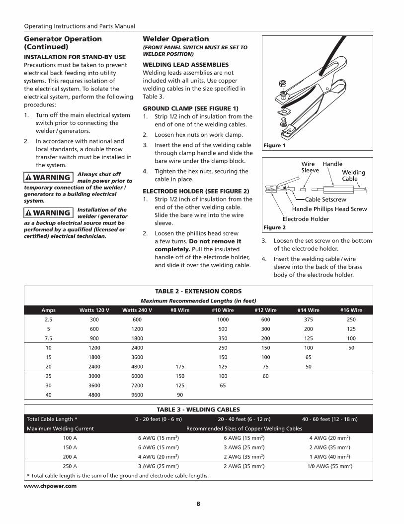
WELDING LEAD ASSEMBLIESWelding leads assemblies are not included with all units. Use copper welding cables in the size specified in Table 3.
GROUND CLAMP (SEE FIGURE 1)1. Strip 1/2 inch of insulation from the
end of one of the welding cables.
2. Loosen hex nuts on work clamp.
3. Insert the end of the welding cable through clamp handle and slide the bare wire under the clamp block.
4. Tighten the hex nuts, securing the cable in place.
ELECTRODE HOLDER (SEE FIGURE 2)1. Strip 1/2 inch of insulation from the
end of the other welding cable. Slide the bare wire into the wire sleeve.
2. Loosen the phillips head screw a few turns. Do not remove it completely. Pull the insulated handle off of the electrode holder, and slide it over the welding cable.
3. Loosen the set screw on the bottom of the electrode holder.
4. Insert the welding cable / wire sleeve into the back of the brass body of the electrode holder.
Figure 1
Electrode Holder
Handle Phillips Head Screw
Handle
Cable Setscrew
WireSleeve Welding
Cable
Figure 2
TABLE 3 - WELDING CABLES
Total Cable Length * 0 - 20 feet (0 - 6 m) 20 - 40 feet (6 - 12 m) 40 - 60 feet (12 - 18 m)
Maximum Welding Current Recommended Sizes of Copper Welding Cables
100 A 6 AWG (15 mm2) 6 AWG (15 mm2) 4 AWG (20 mm2)
150 A 6 AWG (15 mm2) 3 AWG (25 mm2) 2 AWG (35 mm2)
200 A 4 AWG (20 mm2) 2 AWG (35 mm2) 1 AWG (40 mm2)
250 A 3 AWG (25 mm2) 2 AWG (35 mm2) 1/0 AWG (55 mm2)
* Total cable length is the sum of the ground and electrode cable lengths.
TABLE 2 - EXTENSION CORDS
Maximum Recommended Lengths (in feet)
Amps Watts 120 V Watts 240 V #8 Wire #10 Wire #12 Wire #14 Wire #16 Wire
2.5 300 600 1000 600 375 250
5 600 1200 500 300 200 125
7.5 900 1800 350 200 125 100
10 1200 2400 250 150 100 50
15 1800 3600 150 100 65
20 2400 4800 175 125 75 50
25 3000 6000 150 100 60
30 3600 7200 125 65
40 4800 9600 90

9
www.chpower.com
GW4500
Welder Operation (Continued)5. Tighten the set screw, securing the
cable in place.
6. Slide the insulated handle onto the electrode holder and tighten the phillips head screw. Do not overtighten the phillips head screw. Overtightening will damage the insulated handle.
DINSE PLUGS (SEE FIGURE 3)1. Strip 1/2 inch of insulation from the
opposite end of the welding cable.
2. Insert this end of the welding cable through the dinse plug boot and slide the bare wire into the wire sleeve.
3. Insert the welding cable/wire sleeve assembly into the back of the dinse plug.
4. Tighten the set screw, securing the cable in place.
5. Slide the boot over the hex portion of the dinse plug.
6. Repeat for the other lead.
Welding1. Verify that the surfaces of metals
to be joined are free from dirt, rust, paint, oil, scale or other contaminants. These contaminants make welding difficult and cause poor welds.
All persons operating this
equipment or in the area while equipment is in use must wear protective welding gear including: eye protection with proper shade (minimum shade 10), flame resistant clothing, leather welding gloves, and full foot protection.
If heating, welding, or cutting materials
that are galvanized, zinc plated, lead, or cadmium plated refer to the General Safety Information Section for instructions. Extremely toxic fumes are created when these metals are heated.
2. Connect the work clamp to the work piece. Make sure the contact is on bare metal and not obstructed by paint, varnish, corrosion, or non-metallic materials.
3. Insert the exposed part of the electrode (the end with no flux) into the jaws of the electrode holder.
4. Set the amperage adjustment knob to the proper amperage for the electrode diameter. Refer to the chart on the front panel for proper electrode current settings.
The electrode holder and rod are
electrically “live” (current potential) when the engine is running.
5. Position the electrode to begin weld, lower the welding helmet or position the hand shield, and strike an arc. Adjust weld amperage as needed.
6. When finished welding, turn engine off and store unit properly.
DUTY CYCLE / THERMOSTATIC PROTECTIONWelder duty cycle is the percentage of actual weld time that can occur in a ten minute interval. For example, at a 10% duty cycle, actual welding can occur for one minute, then the welder must cool for nine minutes.
Internal components of this welder are protected from overheating with an automatic thermal switch.
MaintenanceINFREQUENT USAGEIf the welder / generator is used infrequently, starting difficulty may occur. To help prevent this, the welder / generators should be run for approximately 30 minutes per week.
STORAGEIf the welder / generators is not to be used for extended periods of time, the following pre-storage procedures should be performed:
1. Make sure engine oil is filled to the proper level.
2. Drain all fuel from the tank, lines, carburetor and fuel valve.
3. Remove the spark plug, and pour approximately one teaspoon of oil into the spark plug hole.
4. Pull the starter cord several times to spread the oil throughout the cylinder.
5. Slowly pull the starter cord, until resistance is felt. This indicates that the piston is moving upward on the compression cycle, and the intake and exhaust valves are closed. (The piston pushes a small amount of air from the spark plug hole on compression.)
6. Use of fuel stabilizers or anti-gumming agents in the fuel system can help prevent the build up of gum and varnish.
Whenever the welder / generator is stored, be sure that the fuel shut-off valve is in the closed position.
Refer to the engine manual that accompanies this unit for instructions regarding maintenance of engine components.
Never tamper with engine speed
settings or welder / generators frequency settings. Any governor adjustments should be made by qualified personnel only.
WELD CABLES1. Check condition of weld cables and
immediately repair or replace any cables with damaged insulation.
2. Check condition of electrode holder insulating pieces and immediately replace cracked or missing parts.
EVERY 3 MONTHSReplace any unreadable labels on the welder. Use compressed air to blow all dust and lint from the ventilation openings.
Dinse Plug
BootSet Screw
Wire Sleeve
WeldingCable
Figure 3

10
www.chpower.com
Operating Instructions and Parts Manual
Welding GuidelinesGENERALThis line of welding machines utilizes a process known as Shielded Metal-Arc Welding (SMAW). This process is used to bond metals by heating them with an electric arc created between the electrode and the work piece.
Electrodes used for shielded metal arc welding have two parts. The inner core is a metal rod or wire that should be similar in composition to the base metal. The outer coating is called flux. Various types of flux exist. Each coating is used for a particular welding situation.
While the metal is molten, it can be contaminated by elements in the air. This contamination could weaken the weld. The flux coating creates a protective barrier called slag that protects the molten metal from contaminants.
When current (amperage) flows through the circuit to the electrode, an arc is formed between the end of the electrode and the work piece. The arc melts the electrode and the work piece. The melted metal of the electrode flows into the molten crater and forms a bond with the work piece as shown in Figure 4.
NOTE: Discontinue using and discard electrodes that burn down to 1 to 2 inches from the electrode holder.
STRIKING AN ARCPlace the bare end of the electrode in the holder. Grip the holder lightly to reduce tiring of the hand and arm.
NOTE: Always keep the jaws of the holder clean to insure good electrical contact with the electrode.
Be careful not to touch the work piece
or welding bench with the electrode as this causes arc flashes.
The best method of striking an arc is the scratching method. Drag the electrode at an angle along the surface much like striking a match. Upon contact with the plate, lift the electrode approximately 1/16” off the surface or it will stick (See Figure 5).
NOTE: Should the electrode stick to the work piece, break it loose by quickly twisting or bending at the holder while pulling upward. If the electrode does not break loose, disengage the electrode by releasing it from the holder.
ELECTRODE TYPE AND SIZEFour types of electrodes are recommended for this welder. The electrodes are commonly known by the AWS (American Welding Society) designation as follows:
1. E-6011 Deep penetrating
• Flat bead with deep penetrating arc.
• For rusted or dirty mild steel general repair work.
2. E-6013 General Purpose
• All position, smooth deposit rod with low spatter.
• For all mild steel and general purpose work.
3. E-7014 Fast fill
• Smooth bead and fast deposition
• Ideal for joints with poor fitup and general repair work.
4. E-7018-AC High Strength
• Ideal for pipes and structural applications.
• Low hydrogen reduces porosity for a strong weld.
NOTE: Only the E-7018-AC electrode is recommended for use with these welders. Other E-7018 electrodes are designed for use with higher open circuit voltages than these welders are capable of producing. Recommended electrode diameter is 3/32 inch or 1/8 inch.
ARC WELDING BASICSFour basic techniques affect weld quality. These are: amperage setting, weld angle, arc length, and travel speed. Proper use of these techniques is necessary for good weld quality.
AMPERAGE SETTING
The correct amperage involves the adjustment of the welding machine to the required amp setting. This is regulated by a knob on the welder. The amperage required depends on the size (diameter) of electrode used and the thickness of the work piece.
Consult specifications listed on the welder. Excessive amps burn through light metals and the weld bead is flat and porous (See Figure 7). The bead appears high and irregular if the amperage is too low.
WELD ANGLE
Weld angle is the angle at which the electrode is held during the welding process. Using the correct angle ensures proper penetration and bead formation. Electrode angle involves two positions - travel angle and work angle (See Figure 6).
Travel angle is the angle in the line of welding and may vary from 5º to 45º from the vertical, depending on welding conditions.
1/16 inch
Same as Electrode Diameter
Figure 5 - Scratching Method
Flux
SlagWeld
Wire
Crater
Work Piece
Figure 4 - Weld Components

11
www.chpower.com
GW4500
Welding Guidelines (Continued)Work angle is the angle from horizontal, measured at right angles to the line of welding.
For most applications, a 45º travel angle and 45º work angle is sufficient. For specific applications, consult an arc welding handbook.
NOTE: Right handed welders should weld from left to right. Left handed welders should weld from right to left. The electrode should always point into the weld puddle as shown.
ARC LENGTH
Arc length is the distance from the work piece to the tip of the electrode, the distance which the arc must travel. A proper arc length is essential to generate the heat needed for welding (See Figure 7). An arc that is too long produces an unstable arc, reduces penetration, increases spatter, and causes flat and wide beads. Too short
an arc does not create enough heat to melt the work piece, the electrode has a tendency to stick, penetration will be poor, and uneven beads with irregular ripples result. A proper arc should be no longer than the diameter of the rod.
The sound of a proper arc is a steady, crisp sizzle, similar to bacon frying.
TRAVEL SPEED
The travel speed is the rate at which the electrode is moved across the weld area (See Figure 7). When the speed is too fast, the bead is narrow and bead ripples are pointed as shown. When the speed is to slow, the weld metal piles up and the bead is high and wide. To control travel speed, watch the width of the weld bead (not the arc) when welding. The weld bead is the orange, molten metal behind the arc. The width should be approximately twice the diameter of the welding rod. Control travel speed to obtain a consistent bead width.
5º - 45º
Travel Angle
Work Angle
Figure 6 - Weld Angle
W
Work Piece
Figure 7 - Weld Appearance
NOTE: Weld bead width (W) should be approximately twice the diameter for the electrode rod used.
Amperage Too Low
Amperage Too High
Arc Length Too Short
Speed Too Fast
Speed Too Slow
Normal Amps, Arc Length,
Speed
Arc Length Too Long

12
www.chpower.com
Operating Instructions and Parts Manual
Welding Guidelines (Continued)SLAG REMOVAL
Wear ANSI approved safety glasses (ANSI
Standard Z87.1) and protective clothing when removing slag. Hot, flying debris can cause personal injury to anyone in the area.
After completing the weld, wait for the welded sections to cool. A protective coating called slag now covers the weld bead which prevents contaminants in the air from reacting with the molten metal. Once the weld cools to the point that it is no longer glowing red, the slag can be removed. Removal is done with a chipping hammer. Lightly tap the slag with the hammer and break it loose from the weld bead. The final clean-up is done with a wire brush. When making multiple weld passes, remove the slag before each pass.
WELDING POSITIONS
Four basic welding positions can be used; flat, horizontal, vertical, and overhead. Welding in the flat position is easier than any of the others because welding speed can be increased, the molten metal has less tendency to run, better penetration can be achieved, and the work is less fatiguing.
Other positions require different techniques such as a weaving pass, circular pass, and jogging. A higher skill level is required to complete these welds.
All work should be performed in the flat position if possible. For specific applications, consult an arc welding handbook.
WELD PASS
Sometimes more then one pass is necessary to fill the joint. The root pass is first, followed by filler passes and the cover pass (See Figures 8 and 9). If the pieces are thick, it may be necessary to bevel the edges that are joined at a 60º angle. Remember to remove the slag before each pass.
TESTING WELDER / GENERATOR DIODES
The following method eliminates the need to disconnect the diodes from the welder / generators wiring.
1. Use a 12 Volt battery and automotive lamp (Type 5001) to test the diodes in the welder / generators.
2. Connect the battery and lamp as shown in Figure 10.
3. If the diodes are operating properly, the lamp illuminates brightly when the battery polarity is correct, and goes dim when battery polarity is reversed.
Cover
Filler
Root
Figure 8 - Weld Passes Figure 9 - Multiple Weld Passes
Lamp Off
Lamp On
Figure 10 - Diode Test Procedure
4. If there is no change in lamp brightness when polarity is reversed, the diodes must be replaced.
For testing of rotor, stator, or field
windings, consult an authorized service center.

13
www.chpower.com
GW4500
Troubleshooting Chart - General
Symptom Possible Cause(s) Corrective Action
Engine will not start 1. Engine switch is set to "OFF".2. Fuel valve is turned to "CLOSE".3. Choke is open.4. Engine is out of gas.5. Engine is filled with contaminated or
old gas6. Spark plug is dirty.7. Spark plug is broken.8. Unit is not on level surface.
9. Oil is low.
1. Set engine switch to "ON".2. Turn fuel valve to "OPEN" position.3. Close the choke.4. Add gas.5. Change the gas in the engine.
6. Clean spark plug.7. Replace spark plug.8. Move unit to a level surface to prevent low oil shutdown from
triggering.9. Add or replace oil.
Engine runs but there is no electrical output
1. Circuit reset button is off.
2. Bad connecting of wires / cables.3. Bad electrical device connected to
generator / welder.
1. Wait for 2 minutes and push the circuit reset button to the "ON" position.
2. If you are using an extension cord, try a different one.3. Try connecting a different device.
Generator / welder runs but does not support all electrical devices connected.
1. Generator / welder is overloaded
2. Short in one of the connected devices.3. Air cleaner is dirty.
1. Turn off all electrical devices. Unplug all electrical devices. Turn off generator / welder. Wait several minutes. Restart generator / welder. Try connecting fewer electrical loads to the generator / welder.
2. Try disconnecting any faulty or short-circuited electrical loads.3. Clean or replace air cleaner.
Troubleshooting Chart - Generator
Symptom Possible Cause(s) Corrective Action
No output voltage 1. Engine speed is too slow2. Open, shorted, or incorrect wiring3. Faulty capacitor4. Open or shorted field windings5. Open diodes6. Front panel switch set incorrectly7. Circuit breaker tripped
1. Adjust engine speed ★2. Referring to the wiring diagram, clean and reconnect all wiring ★3. Replace capacitor ★4. Test winding resistance, replace field winding if necessary ★5. Test diodes, replace if necessary ★6. Set front panel switch to generator7. Reset circuit breaker
Low output voltage with no load
1. Engine speed is too slow2. Open diodes3. Faulty capacitor4. Open or shorted fi eld windings5. Voltage setting on front panel
incorrect
1. Adjust engine speed ★2. Test diodes, replace if necessary ★3. Replace capacitor ★4. Test winding resistance, replace field winding if necessary ★5. Adjust setting on front panel
High output voltage with no load
1. Faulty capacitor2. Engine speed is too fast3. Voltage setting on front panel
incorrect
1. Replace capacitor ★2. Adjust engine speed ★3. Adjust setting on front panel
Low output voltage under load
1. Open diode2. Engine speed too slow at full load3. Excessive load applied4. Voltage setting on front panel
incorrect
1. Test diodes, replace if necessary ★2. Adjust engine speed ★3. Reduce the applied load4. Adjust setting on front panel
Erratic output voltage
1. Unbalanced engine2. Dirty, corroded, or loose wiring
connection3. Unstable load applied
1. Refer to engine manual2. Referring to the wiring diagram, clean and reconnect all wiring ★
3. Remove all loads, then apply each one individually to determine which one is causing erratic function
Noisy operation 1. Loose welder / generators or engine bolt
2. Short circuit in welder / generators field or load
3. Faulty bearing
1. Tighten all mountings
2. Test winding resistance, replace fi eld winding if necessary ★ Test load devices for shorts. Replace defective load device.3. Replace bearing
★ These diagnostic and repair procedures should be performed by an authorized service center.

14
www.chpower.com
Operating Instructions and Parts Manual
Troubleshooting Chart - Welder
Symptom Possible Cause(s) Corrective Action
Welder runs but does not weld
1. Inadequate current at electrode
2. Poor connections at welder3. Front panel switch set incorrectly4. Open, shorted, or incorrect wiring5. Faulty capacitor6. Open or shorted field windings7. Open diodes
1. Check work clamp, cable and connection to work piece. Check electrode cable and clamp
2. Check all welder external connections3. Set front panel switch to weld4. Referring to the wiring diagram, clean and reconnect all wiring ★5. Replace capacitor ★6. Test winding resistance, replace field winding if necessary ★7. Test diodes, replace if necessary ★
Welder gives trickle shocks
1. Accidental contact with work piece2. Current leakage caused by moist
clothing or work area
1. Avoid contact with work piece2. Make sure clothing and work area are dry
Arc diffi cult to strike 1. Wrong type of electrode.2. Electrode diameter too large3. Work piece not properly grounded4. Engine speed is too slow
1. Verify that electrode is for alternating current (AC)2. Use smaller diameter electrode3. Verify proper grounding. (No paint, varnish or corrosion)4. Adjust engine speed
★ These diagnostic and repair procedures should be performed by an authorized service center.
Troubleshooting Chart - Welds
Symptom Possible Cause(s) Corrective Action
Bead is intermittently too thin or too thick
1. Inconsistent travel speed2. Output amp setting incorrect
1. Carefully watch and control the width of the molten weld bead2. Adjust output amp setting or change to smaller diameter electrode
Ragged depressions at edge of weld
1. Travel speed too fast2. Arc length too short3. Output amp setting too high
1. Watch orange molten weld puddle and control bead width2. Practice running electrode across workpiece with welder OFF3. Reduce output amp setting
Weld bead does not penetrate base metal
1. Inconsistent travel speed2. Output amp setting too low3. Electrode diameter too large
1. Decrease and maintain constant travel speed2. Increase output amp setting3. Change to smaller diameter electrode
Electrode sticks to workpiece
1. Arc length short2. Amp setting low3. Incorrect electrode
1. Lift electrode to correct arc length as soon as arc is struck2. Increase amp setting or change to smaller diameter electrode3. Verify electrode is suitable for 62.5 V open circuit voltage
Electrodes sputter and stick
Damp electrodes Use dry electrodes and store in dry location
15
www.chpower.com
GW4500
Wel
din
g
Imp
edan
ce
Gen
.W
eld
.
Ro
tor
RedWhite
Brown
Battery Charger12V ACBlue Brown
Grey Red
Black White
Yellow Green
Mai
n W
ind
ing
Brown
Red
White
Green
Generator/WelderPower Switch
24
68
1012
1416
1820
2224
13
57
911
1315
1719
2123
Cap
acit
or
Ther
mal
Tri
p
(Fit
ted
Insi
de
the
Win
din
gs)
Violet
BlackBlue
GreyRed
BrownYellow
Orange
Au
xilia
ry W
ind
ing
Wel
din
g C
urr
ent
and
Gen
erat
or
Vo
ltag
e Se
lect
or
R/L
1
White
Orange
115V
230V
BlueEl
ectr
od
eH
old
er
Gro
un
dC
lam
p
12
7 63
45
Adj
usta
ble
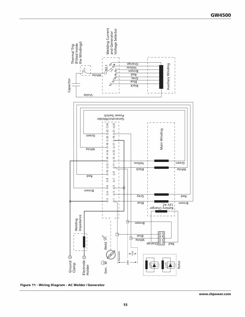
Figure 11 - Wiring Diagram - AC Welder / Generator

16
www.chpower.com
Operating Instructions and Parts Manual
1
27
3
4 56
8
9
10
11
12
13
1415
16
17 18
19
20
11
11
11
21 22
Figure 12
Welder / Generator Assembly

17
www.chpower.com
GW4500
For replacement parts or technical assistance, call 1-800-543-6400
1 Engine - Honda GX270 PM004264AV 1 2 Welded Frame Assembly GW004000AD 1 3 Tie Bracket GN004399AD 1 4 Isomount - Angle (short) GN004405AV 1 5 Isomount - Angle (extended) GN004406AV 1 6 Isomount GN004401AV 1 7 Hat Bracket GW004050AD 1 8 Hex head Screw - M8 - 1.25 x 60 mm ▲ 1 9 Flat Washer - 2 inch OD ▲ 1 10 Hex head Screw - 5/16 - 18 x 3/4 inch ▲ 4 11 Serrated Flange Nut - 5/16 - 18 ▲ 9 12 Ground Wire GN003811AJ 1 13 Hex head Screw - 5/16 - 18 x 1-1/4 inch ▲ 1 14 Flat Washer - 5/16 inch ID ▲ 2 15 Wing Nut - 5/16 - 18 ▲ 1 16 Ground Clamp WC100100AV 1 17 Electrode Holder WC200200AV 1 18 Dinse Plug WC000200AV 2 19 Welding Cable - 6 AWG (14 foot) ▲ 1 20 Welding Cable - 6 AWG (6 foot) ▲ 1 21 Warning Decal DK689201AV 1 22 CPSC Warning Decal DK689202AV 1
▲ Standard hardware item, available at local hardware stores
Replacement Parts List
Ref. No. Description Part Number Qty.
Please provide following information: - Model number - Serial number (if any) - Part description and number as shown in parts list
Address parts correspondence to:Campbell HausfeldAttn: Parts Dept.100 Production DriveHarrison, OH 45030 USA
18
www.chpower.com
Operating Instructions and Parts Manual
1
2
3
28
27
26
25
24
23
22
21
20
19
18
17
16
15
14
13
12
11
10
9
8
7
6
5
4
4
10
28
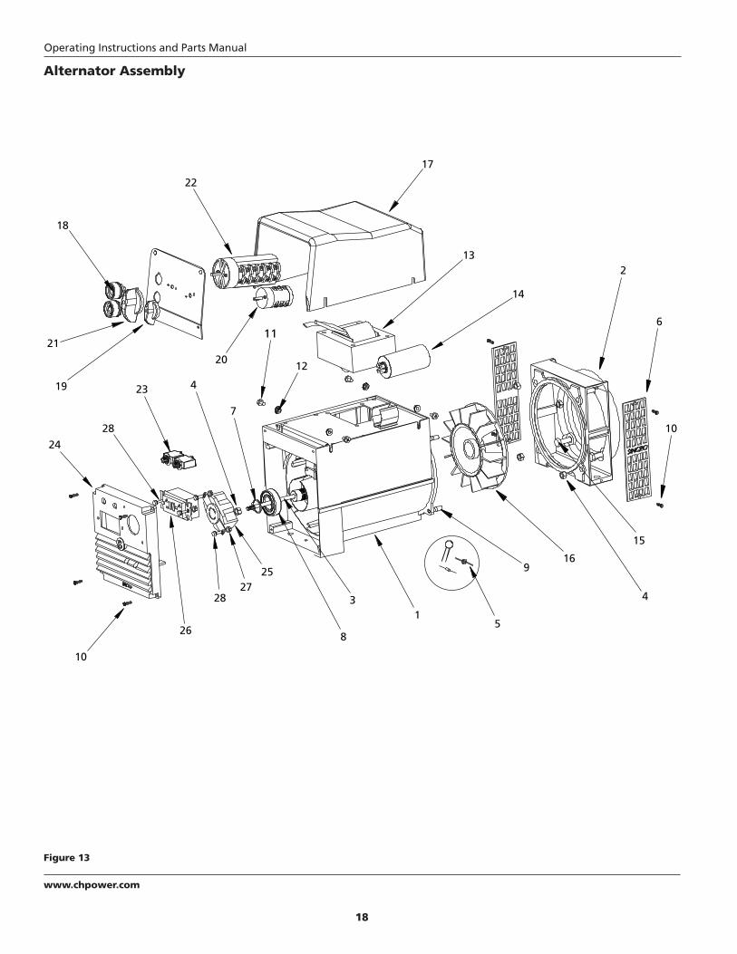
Figure 13
Alternator Assembly

19
www.chpower.com
GW4500
For replacement parts or technical assistance, call 1-800-543-6400
1 Alternator - 4kW, 140A AC (includes items 2 through 22) GW001000AV 1 2 Engine Adapter GN002301SV 1 3 Rotor Tie Rod GN002304SV 1 4 Nyloc Nut - M8-1.25 ▲ 5 5 Diode, Suppressor, Capacitor Kit (2 each) GN002337SJ 1 6 Air Outlet Guard GN002310SV 2 7 Retaining Ring GN002311SV 1 8 Bearing GN002312SV 1 9 Stud - M8-1.25 x 30mm GN002313SV 4 10 Phillips Head Screw - M5-0.8 x 10mm ▲ 8 11 Phillips Head Screw - M6-1.0 x 10mm ▲ 4 12 Serrated Flange Nut - M6-1.0 ▲ 4 13 Inductor GW001050SV 1 14 Capacitor - 35mF, 450V GW001016SV 1 15 Hex Head Screw - 3/8-16 x 1 inch ▲ 4 16 Alternator Fan GW001020SV 1 17 Top Cover GW001002SV 1 18 Dinse Socket - 200A WC000300AV 2 19 Commutator Knob - Small WC400401AV 1 20 Commutator - Output GW001045SV 1 21 Commutator Knob - Large GW001046SV 1 22 Commutator - Gen/Weld GW001047SV 1 23 Circuit Breaker - 25A, 250V GN003601AV 2 24 Endbell with Nutcover - GFCI, T-lock GN002480SJ 1 25 Twistlock Receptacle - 125/250V, 20A GN003501AV 1 26 Duplex Receptacle - 120V, 20A GN003403AV 1 27 Nylock Nut - #8-32 ▲ 4 28 Hex Head Screw - #8-32 x .75 inch ▲ 4
▲ Standard hardware item, available at local hardware stores
Replacement Parts List
Ref. No. Description Part Number Qty.
Please provide following information: - Model number - Serial number (if any) - Part description and number as shown in parts list
Address parts correspondence to:Campbell HausfeldAttn: Parts Dept.100 Production DriveHarrison, OH 45030 USA

20
www.chpower.com
Operating Instructions and Parts Manual
Limited Warranty
1. DURATION: The manufacturer warrants that it will repair, at no charge for parts or labor, the welder, welding gun, or cables, proven defective in material or workmanship, during the following time period(s) after date of original retail purchase:
For 5 Years: The Welder Transformer and RectifierFor 3 Years: The Entire Welder and Engine Driven Welder Generators (excluding clamps, welding gun, electrode holder,
cables, or accessories packed with the welder)For 90 Days: The Welding Clamps, MIG Gun, Electrode Holder, Accessories, and Welding Cables (as applicable)
2. WHO GIVES THIS WARRANTY (WARRANTOR): Campbell Hausfeld / Scott Fetzer Company, 100 Production Drive, Harrison, Ohio, 45030, Telephone: (800) 543-6400
3. WHO RECEIVES THIS WARRANTY (PURCHASER): The original purchaser (other than for purposes of resale) of the Campbell Hausfeld Industrial product.
4. WHAT IS COVERED UNDER THIS WARRANTY: Substantial defects in material and workmanship which occur within the duration of the warranty period. This warranty extends to the Welder, the Welders Transformer and Rectifier, Welding Gun or Electrode holder, and cables only.
5. WHAT IS NOT COVERED UNDER THIS WARRANTY:A. Implied warranties, including those of merchantability and FITNESS FOR A PARTICULAR PURPOSE ARE LIMITED IN
DURATION TO THIS EXPRESS WARRANTY. After this period, all risks of loss, from whatever reason, shall be on the purchaser. Some States do not allow limitation on how long an implied warranty lasts, so the above limitations may not apply to you.
B. ANY INCIDENTAL, INDIRECT, OR CONSEQUENTIAL LOSS, DAMAGE, OR EXPENSE THAT MAY RESULT FROM ANY DEFECT, FAILURE, OR MALFUNCTION OF THE CAMPBELL HAUSFELD INDUSTRIAL PRODUCT. Some States do not allow limitations on how long an implied warranty lasts, so above limitations may not apply to you.
C. This warranty does not apply to any accessory items included with the product which are subject to wear from usage; the repair or replacement of these items shall be at the expense of the owner. These MIG items include but are not limited to; Contact Tips, Nozzles, Gun Liners, Drive Rollers, Felt Wire Cleaner. In addition, this warranty does not extend to any damage caused by the untimely replacement or maintenance of any of the previously listed CONSUMABLE parts.
D. Any failure that results from accident, purchaser’s abuse, neglect or failure to operate products in accordance with instructions provided in the owner’s manual(s) supplied with product.
E. Pre-delivery service, i.e. assembly, oil or lubricants, and adjustment.F. Gasoline engine components are expressly excluded from coverage under this limited warranty. Such components
should be returned by the purchaser to the original manufacturer or to its authorized repair stations for service.6. RESPONSIBILITIES OF WARRANTOR UNDER THIS WARRANTY: Repair or replace, at Warrantor’s option, products or
components which have failed within duration of the warranty period.7. RESPONSIBILITIES OF PURCHASER UNDER THIS WARRANTY:
A. Please call 800-543-6400 for warranty assistance.B. Provide dated proof of purchase and maintenance records.C. All welders must be delivered or shipped to the nearest Campbell Hausfeld Authorized Service Center. Freight costs,
if any, must be borne by the purchaser.D. Use reasonable care in the operation and maintenance of the products as described in the owner’s manual(s).
8. WHEN WARRANTOR WILL PERFORM REPAIR OR REPLACEMENT UNDER THIS WARRANTY:Repair or replacement will be scheduled and serviced according to the normal work flow at the servicing location, and depending on the availability of replacement parts.
This Limited Warranty gives you specific legal rights and you may also have other rights which vary from state to state.