propeller owner's manual - hartzell...
TRANSCRIPT
Manual No. 48661-00-86OriginalDecember 2015
Propeller Owner's Manual and Logbook
Raptor Turbine Propeller Series with Composite Blades
Models: ( )D3-( )( )( )
Hartzell Propeller Inc.One Propeller PlacePiqua, OH 45356 - 2634 U.S.A.Ph: 937 - 778 - 4200 (Hartzell Propeller Inc.) Ph: 937 - 778 - 4379 (Product Support)Product Support Fax: 937-778-4215

Propeller Owner's Manual486
61-00-86 Inside Cover Orig Dec/15COVER
© 2015 - Hartzell Propeller Inc. - All rights reserved

61-00-86
Propeller Owner's Manual486
MESSAGEPage 1
Orig. Dec/15
As a fellow pilot, I urge you to read this Manual thoroughly. It contains a wealth of information about your new propeller.
The propeller is among the most reliable components of your airplane. It is also among the most critical to flight safety. It therefore deserves the care and maintenance called for in this Manual. Please give it your attention, especially the section dealing with Inspections and Checks.
Thank you for choosing a Hartzell propeller. Properly maintained it will give you many years of reliable service.
Jim Brown Chairman, Hartzell Propeller Inc.
Page 2Orig. Dec/15MESSAGE 61-00-86
Propeller Owner's Manual486
People who fly should recognize that various types of risks are involved; and they should take all precautions to minimize them, since they cannot be eliminated entirely. The propeller is a vital component of the aircraft. A mechanical failure of the propeller could cause a forced landing or create vibrations sufficiently severe to damage the aircraft, possibly causing it to become uncontrollable.
Propellers are subject to constant vibration stresses from the engine and airstream, which are added to high bending and centrifugal stresses.
Before a propeller is certified as being safe to operate on an airplane, an adequate margin of safety must be demonstrated. Even though every precaution is taken in the design and manufacture of a propeller, history has revealed rare instances of failures, particularly of the fatigue type.
It is essential that the propeller is properly maintained according to the recommended service procedures and a close watch is exercised to detect impending problems before they become serious. Any grease or oil leakage, loss of air pressure, unusual vibration, or unusual operation should be investigated and repaired, as it could be a warning that something serious is wrong.
WARNING
61-00-86
Propeller Owner's Manual486
MESSAGEPage 3
Orig. Dec/15
For operators of uncertified or experimental aircraft an even greater level of vigilance is required in the maintenance and inspection of the propeller. Experimental installations often use propeller-engine combinations that have not been test and approved. In these cases, the stress on the propeller and, therefore, its safety margin is unknown. Failure could be as severe as loss of propeller or propeller blades and cause loss of propeller control and/or loss of aircraft control.
Hartzell Propeller Inc. follows FAA regulations for propeller certification on certificated aircraft. Experimental aircraft may operate with unapproved engines or propellers or engine modifications to increase horsepower, such as unapproved crankshaft damper configurations or high compression pistons. These issues affect the vibration output of the engine and the stress levels on the propeller. Significant propeller life reduction and failure are real possibilities.
Frequent inspections are strongly recommended if operating with a non-certificated installation; however, these inspections may not guarantee propeller reliability, as a failing device may be hidden from the view of the inspector. Propeller overhaul is strongly recommended to accomplish periodic internal inspection.
Visually inspect composite blades for cracks with particular emphasis on the blade parting line. Inspect hubs, with particular emphasis on each blade arm for cracks. Eddy current equipment is recommended for hub inspection, since cracks are usually not apparent.
Page 4Orig. Dec/15MESSAGE 61-00-86
Propeller Owner's Manual486
(This page is intentionally blank.)

61-00-86
Propeller Owner's Manual486
REVISION HIGHLIGHTSPage 5
Orig. Dec/15
REVISION HIGHLIGHTS
• Original Issue manual issued in its entirety

Page 6Orig. Dec/15REVISION HIGHLIGHTS 61-00-86
Propeller Owner's Manual486
(This page is intentionally blank.)
61-00-86
Propeller Owner's Manual486
REVISION HIGHLIGHTSPage 7
Orig. Dec/15
REVISION HIGHLIGHTS
1. IntroductionA. General
This is a list of current revisions that have been issued against this manual. Please compare it to the RECORD OF REVISIONS page to ensure that all revisions have been added to the manual.
B. Components(1) Revision No. indicates the revisions incorporated in this
manual.(2) Issue Date is the date of the revision.(3) Comments indicates the level of the revision.
(a) New Issue is a new manual distribution. The manual is distributed in its entirety. All the page revision dates are the same and no change bars are used.
(b) Reissue is a revision to an existing manual that includes major content and/or major format changes. The manual is distributed in its entirety. All the page revision dates are the same and no change bars are used.
(c) Major Revision is a revision to an existing manual that includes major content or minor content changes over a large portion of the manual. The manual is distributed in its entirety. All the page revision dates are the same, but change bars are used to indicate the changes incorporated in the latest revision of the manual.
(d) Minor Revision is a revision to an existing manual that includes minor content changes to the manual. Only the revised pages of the manual are distributed. Each page retains the date and the change bars associated with the last revision to that page.
Page 8Orig. Dec/15REVISION HIGHLIGHTS 61-00-86
Propeller Owner's Manual486
Revision No. Issue Date Comments Original Dec/15 New Issue

Page 9 Orig. Dec/1561-00-86 RECORD OF REVISIONS
RECORD OF REVISIONS
Propeller Owner's Manual 486
Rev. No. Issue Date Date Inserted Inserted By
Orig. Dec/15 Dec/15 HPI

Page 10 Orig. Dec/1561-00-86 RECORD OF REVISIONS
Propeller Owner's Manual 486
(This page is intentionally blank.)
Page 11 Orig. Dec/15 61-00-86RECORD OF TEMPORARY REVISIONS
RECORD OF TEMPORARY REVISIONS TR Issue Date Inserted Date Removed No. Date Inserted By Removed By
Propeller Owner's Manual 486

Page 12 Orig. Dec/15 61-00-86RECORD OF TEMPORARY REVISIONS
Propeller Owner's Manual 486
(This page is intentionally blank.)

61-00-86 SERVICE DOCUMENTS LIST Page 13
Orig. Dec/15
Propeller Owner's Manual486
SERVICE DOCUMENTS LIST
CAUTION 1: DO NOT USE OBSOLETE OR OUTDATED INFORMATION. PERFORM ALL INSPECTIONS OR WORK IN ACCORDANCE WITH THE MOST RECENT REVISION OF A SERVICE DOCUMENT. INFORMATION CONTAINED IN A SERVICE DOCUMENT MAY BE SIGNIFICANTLY CHANGED FROM EARLIER REVISIONS. FAILURE TO COMPLY WITH INFORMATION CONTAINED IN A SERVICE DOCUMENT OR THE USE OF OBSOLETE INFORMATION MAY CREATE AN UNSAFE CONDITION THAT MAY RESULT IN DEATH, SERIOUS BODILY INJURY, AND/OR SUBSTANTIAL PROPERTY DAMAGE.
CAUTION 2: THE INFORMATION FOR THE DOCUMENTS LISTED INDICATES THE REVISION LEVEL AND DATE AT THE TIME THAT THE DOCUMENT WAS INITIALLY INCORPORATED INTO THIS MANUAL. INFORMATION CONTAINED IN A SERVICE DOCUMENT MAY BE SIGNIFICANTLY CHANGED FROM EARLIER REVISIONS. REFER TO THE APPLICABLE SERVICE DOCUMENT INDEX FOR THE MOST RECENT REVISION LEVEL OF THE SERVICE DOCUMENT.
Service Document Number Incorporation Rev/Date
Page 14Orig. Dec/15SERVICE DOCUMENTS LIST 61-00-86
Propeller Owner's Manual486
(This page is intentionally blank.)

Propeller Owner's Manual 486
Page 15 Orig. Dec/15AIRWORTHINESS LIMITATIONS 61-00-86
AIRWORTHINESS LIMITATIONS
Rev. No. Description of Revision
The Airworthiness Limitations section is FAA approved and specifies maintenance required under 43.16 and 91.403 of the Federal Aviation Regulations unless an alternative program has been approved.
FAA APPROVED
by: ______________________________ date: ____________
Manager, Chicago Aircraft Certification Office,
ACE-115CFederal Aviation Administration

Page 16 Orig. Dec/15AIRWORTHINESS LIMITATIONS 61-00-86
Propeller Owner's Manual486
AIRWORTHINESS LIMITATIONS
1. Replacement Time (Life Limits)A. The FAA establishes specific life limits for certain component
parts, as well as the entire propeller. Such limits require replacement of the identified parts after a specified number of hours of use.
B. The following data summarizes all current information concerning Hartzell Propeller Inc. life limited parts as related to propeller models affected by this manual. These parts are not life limited on other installations; however, time accumulated toward life limit accrues when first operated on aircraft/engine/propeller combinations listed, and continues regardless of subsequent installations (which may or may not be life limited).(1) The propeller models affected by this manual currently
do not have any life limited parts.
FAA APPROVED
by: ______________________________ date: ____________
Manager, Chicago Aircraft Certification Office,
ACE-115CFederal Aviation Administration

LIST OF EFFECTIVE PAGES
Propeller Owner's Manual 486
Chapter Page Revision Date
LIST OF EFFECTIVE PAGES 61-00-86Page 17
Orig. Dec/15
Cover Cover and Inside Cover Orig Dec/15Message 1 thru 4 Orig Dec/15Revision Highlights 5 thru 8 Orig Dec/15Record of Revisions 9 and 10 Orig Dec/15Record of Temporary Revisions 11 and 12 Orig Dec/15Service Documents List 13 and 14 Orig Dec/15Airworthiness Limitations 15 and 16 Orig Dec/15List of Effective Pages 17 and 18 Orig Dec/15Table of Contents 19 thru 26 Orig Dec/15Introduction 1-1 thru 1-20 Orig Dec/15Description and Operation 2-1 thru 2-16 Orig Dec/15Installation and Removal 3-1 thru 3-32 Orig Dec/15Testing and Troubleshooting 4-1 thru 4-12 Orig Dec/15Inspection and Check 5-1 thru 5-36 Orig Dec/15Maintenance Practices 6-1 thru 6-32 Orig Dec/15Anti-Ice and De-Ice Systems 7-1 thru 7-8 Orig Dec/15Records 8-1 thru 8-8 Orig Dec/15

LIST OF EFFECTIVE PAGES 61-00-86Page 18
Orig. Dec/15
Propeller Owner's Manual 486
(This page is intentionally blank.)
Propeller Owner's Manual486
TABLE OF CONTENTSPage 19
Orig. Dec/15 61-00-86
TABLE OF CONTENTS
MESSAGE ...................................................................................... 1
REVISION HIGHLIGHTS ............................................................... 5
RECORD OF REVISIONS ............................................................. 9
RECORD OF TEMPORARY REVISIONS .....................................11
SERVICE DOCUMENTS LIST ..................................................... 13
AIRWORTHINESS LIMITATIONS ................................................ 15
LIST OF EFFECTIVE PAGES ...................................................... 17
TABLE OF CONTENTS ................................................................ 19
INTRODUCTION ......................................................................... 1-1
1. Purpose .................................................................................. 1-3
2. Airworthiness Limitations ........................................................ 1-3
3. AirframeorEngineModifications ............................................ 1-4
4. Restrictions and Placards ....................................................... 1-5
5. General ................................................................................... 1-6A. Personnel Requirements ................................................... 1-6B. Maintenance Practices ....................................................... 1-6C. Continued Airworthiness .................................................... 1-9D. Propeller Critical Parts ....................................................... 1-9
6. Reference Publications ......................................................... 1-10
A. Hartzell Propeller Inc. Publications .................................. 1-10B. References to Hartzell Propeller Inc. Publications ........... 1-12
7. Definitions ............................................................................. 1-13
8. Abbreviations ........................................................................ 1-17
9. Hartzell Propeller Inc. Product Support ................................ 1-18
10.Warranty Service .................................................................. 1-18
11. Hartzell Propeller Inc. Recommended Facilities ................... 1-19

Propeller Owner's Manual486
TABLE OF CONTENTSPage 20
Orig. Dec/15 61-00-86
DESCRIPTION AND OPERATION .............................................. 2-1
1. Functional Description of Constant Speed Propeller Types ... 2-3A. Feathering and Reversing Propellers ( )D3-( )( )( ) Series ........................................................... 2-3
2. Model Designation .................................................................. 2-7
3. Governors ............................................................................. 2-11A. Theory of Operation ......................................................... 2-11B. Governor Types ............................................................... 2-13C.IdentificationofHartzellPropellerInc.Governors ............ 2-13
4. Propeller Ice Protection Systems ......................................... 2-14A. Propeller Anti-ice System ................................................. 2-14B. Propeller De-ice System .................................................. 2-15
INSTALLATION AND REMOVAL ................................................. 3-1
1. Tools, Consumables, and Expendables ................................. 3-3A. Tooling ................................................................................ 3-3B. Consumables ..................................................................... 3-3C. Expendables ...................................................................... 3-3
2. Pre-Installation ........................................................................ 3-4A. Inspection of Shipping Package ......................................... 3-4B. Uncrating ............................................................................ 3-4C. Inspection after Shipment .................................................. 3-4D. Reassembly of a Propeller Disassembled for Shipment .... 3-4
3. Propeller Assembly Installation ............................................... 3-5A. Precautions ........................................................................ 3-5B. Installing ( )D3-( )( )( ) Propeller on the Aircraft Engine ...... 3-9
4. Spinner Installation ............................................................... 3-21
5. Post-Installation Checks ....................................................... 3-28
6. Spinner Removal .................................................................. 3-29
7. Propeller Removal ................................................................ 3-29A. Removal of ( )D3-( )( )( ) Propellers ................................. 3-29
TABLE OF CONTENTS, CONTINUED
Propeller Owner's Manual486
TABLE OF CONTENTSPage 21
Orig. Dec/15 61-00-86
TESTING AND TROUBLESHOOTING ....................................... 4-1
1. Operational Tests .................................................................... 4-3A. Initial Run-Up ..................................................................... 4-3B. Post-Run Check ................................................................. 4-3C. Maximum RPM (Static) Hydraulic Low Pitch Stop Check .. 4-4D. Reverse Pitch Stop Adjustment ......................................... 4-4E. Feathering Pitch Stop Adjustment ...................................... 4-4F. Propeller Ice Protection System ......................................... 4-4
2. Troubleshooting ...................................................................... 4-6A. Hunting and Surging .......................................................... 4-6B. Engine Speed Varies with Airspeed ................................... 4-7C. Loss of Propeller Control ................................................... 4-7D. Failure to Feather (or feathers slowly) ............................... 4-8E. Failure to Unfeather ........................................................... 4-8F. Vibration ............................................................................. 4-9G. Propeller Overspeed ........................................................ 4-10H. Propeller Underspeed ...................................................... 4-10I. Oil or Grease Leakage ..................................................... 4-11
INSPECTION AND CHECK ......................................................... 5-1
1. Pre-Flight Checks ................................................................... 5-3
2. Operational Checks ................................................................ 5-5
3. Required Periodic Inspections and Maintenance ................... 5-7A. Periodic Inspections .......................................................... 5-7B. Periodic Maintenance ........................................................ 5-9C. Airworthiness Limitations ................................................... 5-9D. Overhaul Periods ............................................................. 5-10
4. Inspection Procedures .......................................................... 5-11A. Blade Damage ................................................................. 5-11B. Grease or Oil Leakage ..................................................... 5-11C. Vibration ........................................................................... 5-13D. Tachometer Inspection ..................................................... 5-15
TABLE OF CONTENTS, CONTINUED

Propeller Owner's Manual486
TABLE OF CONTENTSPage 22
Orig. Dec/15 61-00-86
E. Blade Track ...................................................................... 5-17F. Loose Blades .................................................................. 5-19G. Corrosion ......................................................................... 5-19H. Spinner Damage ............................................................. 5-20I. Electric De-ice System ..................................................... 5-20J. Anti-ice System ................................................................ 5-20
5. Special Inspections ............................................................... 5-23A. Overspeed/Overtorque .................................................... 5-23B. Propeller Ground Idle Operating Restrictions .................. 5-25C. Lightning Strike ................................................................ 5-31D. Foreign Object Strike ....................................................... 5-34E. Fire Damage or Heat Damage ......................................... 5-36
6. Long Term Storage ............................................................... 5-36
MAINTENANCE PRACTICES ..................................................... 6-1
1. Cleaning ................................................................................. 6-3A. General Cleaning ............................................................... 6-3B. Spinner Cleaning and Polishing ......................................... 6-5
2. Lubrication .............................................................................. 6-6A. Lubrication Intervals ........................................................... 6-6B. Lubrication Procedure ........................................................ 6-7C. Approved Lubricants ......................................................... 6-10
3. Beta Feedback Block Assemblies ........................................ 6-11A. Inspection ......................................................................... 6-11B. Replacement of the A-3026 Carbon Block Unit in the A-3044 Beta Feedback Block Assembly .......................... 6-11C. Installation of the A-3044 Beta Feedback Block Assembly ................................................................ 6-12
4. Composite Blades ................................................................ 6-15A. Raptor Composite Blades ................................................ 6-15B. Component Life and Service ............................................ 6-16C. Damage Evaluation .......................................................... 6-17D. Repair Determination ....................................................... 6-19
TABLE OF CONTENTS, CONTINUED
INSPECTION AND CHECK, CONTINUED

Propeller Owner's Manual486
TABLE OF CONTENTSPage 23
Orig. Dec/15 61-00-86
E. Personnel Requirements ................................................. 6-20F. Blade Inspection Requirements ....................................... 6-21
5. Painting After Repair ............................................................. 6-24A. General ............................................................................ 6-24B. Painting of Composite Blades ......................................... 6-26
6. Dynamic Balance .................................................................. 6-28A. Overview .......................................................................... 6-28B. Inspection Procedures Before Balancing ......................... 6-29C. Modifying Spinner Bulkhead to Accommodate Dynamic Balance Weights .............................................................. 6-30D. Placement of Balance Weights for Dynamic Balance ...... 6-31
7. Propeller Ice Protection Systems ......................................... 6-32A. Electric De-ice System ..................................................... 6-32B. Anti-ice System ................................................................ 6-32
ANTI-ICE AND DE-ICE SYSTEMS ............................................. 7-1
1. Introduction .............................................................................. 7-3A. Propeller De-ice System .................................................... 7-3B. Anti-ice System .................................................................. 7-3
2. System Description ................................................................. 7-4A. De-ice System .................................................................... 7-4B. Anti-ice System .................................................................. 7-5
3. De-ice System Functional Tests ............................................. 7-5
4. Anti-ice System Functional Tests ............................................ 7-5
5. De-ice and Anti-ice System Inspections ................................. 7-6A. De-ice System Inspections ................................................ 7-6B. Anti-ice System Inspections ............................................... 7-6
6. De-ice and Anti-ice System Troubleshooting .......................... 7-7A. De-ice System Troubleshooting ......................................... 7-7B. Anti-ice System Troubleshooting ....................................... 7-7
TABLE OF CONTENTS, CONTINUED
MAINTENANCE PRACTICES, CONTINUED
Propeller Owner's Manual486
TABLE OF CONTENTSPage 24
Orig. Dec/15 61-00-86
RECORDS ................................................................................... 8-1
1. Introduction .............................................................................. 8-3
2. Record Keeping ....................................................................... 8-3A. Information to be Recorded ................................................ 8-3B. Blade Damage Repair Sheets ............................................ 8-3 ( )78D01B ........................................................................... 8-4
TABLE OF CONTENTS, CONTINUED
Propeller Owner's Manual486
TABLE OF CONTENTSPage 25
Orig. Dec/15 61-00-86
LIST OF FIGURES
Propeller Flange Description .........................Figure 2-1 ............. 2-6
Governor in Onspeed Condition ....................Figure 2-7 ........... 2-10
Governor in Underspeed Condition ...............Figure 2-8 ........... 2-10
Governor in Overspeed Condition .................Figure 2-9 ........... 2-10
Tool for Decompressing ( )D3-( )( )( ) Series External Beta System .................................Figure 3-1 ............. 3-8
Installing Propeller on Engine Flange ............Figure 3-2 ........... 3-12
Mounting Bolt and Washer ............................Figure 3-3 ........... 3-13
Determining Torque Value When Using Torquing Adapter ........................................Figure 3-4 ........... 3-14
Diagram of Torquing Sequence for Propeller Mounting Bolts .......................Figure 3-5 ........... 3-15
Beta Feedback Block Assembly and Beta Ring Clearance ...........................Figure 3-6 ........... 3-16
Beta Feedback Block Assembly ....................Figure 3-7 ........... 3-16
Resistance Check Locations .........................Figure 3-8 ........... 3-20
Resistance Check of the Dome .....................Figure 3-9 ........... 3-22
Spinner Assembly .........................................Figure 3-10 ......... 3-24
Spinner Reassembly Procedures ..................Figure 3-11 ......... 3-25
Optional Tape on the Forward Bulkhead .......Figure 3-12 ......... 3-26
Checking Blade Track....................................Figure 5-1 ........... 5-16
Blade Play .....................................................Figure 5-2 ........... 5-16
Turbine Engine Overspeed Limits .................Figure 5-3 ........... 5-21
Turbine Engine Overtorque Limits .................Figure 5-4 ........... 5-22
Example of an Evaluation of Ground Idle RPM Check ........................Figure 5-5 ........... 5-26
Corrective Action Required ............................Figure 5-6 ........... 5-27
Propeller Owner's Manual486
TABLE OF CONTENTSPage 26
Orig. Dec/15 61-00-86
LIST OF TABLES
Blade Model Designations .............................Table 2-1 .............. 2-8
Blade Type and Blade Model Designations ...Table 2-2 .............. 2-9
Propeller/Engine Flange O-rings and Mounting Hardware .............................Table 3-1 ............ 3-10
Torque Table ..................................................Table 3-2 ............ 3-11
Resistance Checks ........................................Table 3-3 ............ 3-21
Approved Touch-up Paints ............................Table 6-1 ............ 6-25
Evidence of Lightning Strike Damage to Composite Blade ....................................Figure 5-7 ........... 5-32
Lubrication Fitting .........................................Figure 6-1 ............. 6-4
Lubrication Label ...........................................Figure 6-2 ............. 6-8
Section of Typical Raptor Composite Blade ........Figure 6-3 ........... 6-14
Basic Components of a Raptor Composite Blade ........................................Figure 6-4 ........... 6-14
LIST OF FIGURES, CONTINUED
Propeller Owner’s Manual 486
INTRODUCTION 61-00-86Page 1-1
Orig. Dec/15
INTRODUCTION - CONTENTS
1. Purpose .................................................................................. 1-3
2. Airworthiness Limitations ........................................................ 1-3
3. AirframeorEngineModifications ............................................ 1-4
4. Restrictions and Placards ....................................................... 1-5
5. General ................................................................................... 1-6A. Personnel Requirements ................................................... 1-6B. Maintenance Practices ....................................................... 1-6C. Continued Airworthiness .................................................... 1-9D. Propeller Critical Parts ....................................................... 1-9
6. Reference Publications ......................................................... 1-10
A. Hartzell Propeller Inc. Publications .................................. 1-10B. References to Hartzell Propeller Inc. Publications ........... 1-12
7. Definitions ............................................................................. 1-13
8. Abbreviations ........................................................................ 1-17
9. Hartzell Propeller Inc. Product Support ................................ 1-18
10.Warranty Service .................................................................. 1-18
11. Hartzell Propeller Inc. Recommended Facilities ................... 1-19

Propeller Owner’s Manual 486
INTRODUCTION 61-00-86Page 1-2
Orig. Dec/15
(This page is intentionally blank.)
Propeller Owner’s Manual 486
INTRODUCTION 61-00-86Page 1-3
Orig. Dec/15
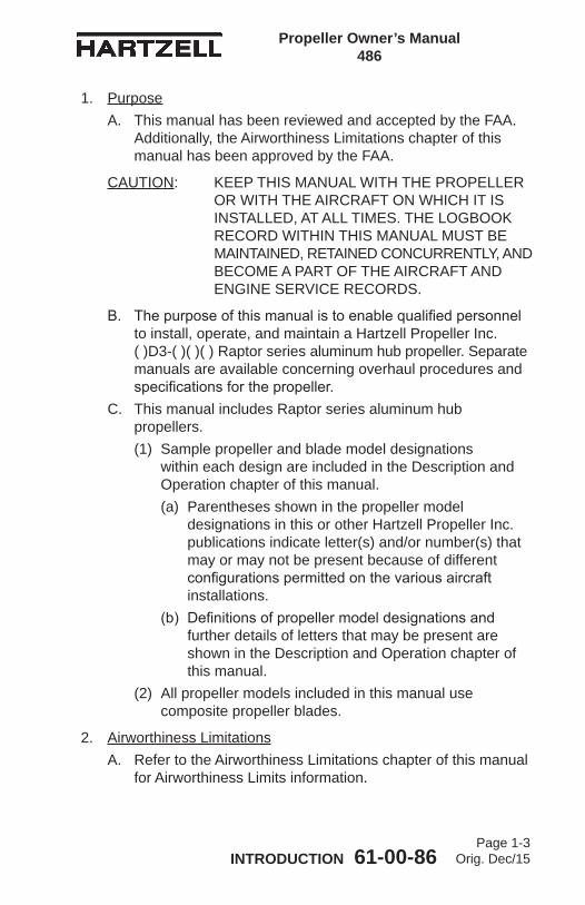
1. PurposeA. This manual has been reviewed and accepted by the FAA.
Additionally, the Airworthiness Limitations chapter of this manual has been approved by the FAA.
CAUTION: KEEP THIS MANUAL WITH THE PROPELLER OR WITH THE AIRCRAFT ON WHICH IT IS INSTALLED, AT ALL TIMES. THE LOGBOOK RECORD WITHIN THIS MANUAL MUST BE MAINTAINED, RETAINED CONCURRENTLY, AND BECOME A PART OF THE AIRCRAFT AND ENGINE SERVICE RECORDS.
B. Thepurposeofthismanualistoenablequalifiedpersonnelto install, operate, and maintain a Hartzell Propeller Inc. ( )D3-( )( )( ) Raptor series aluminum hub propeller. Separate manuals are available concerning overhaul procedures and specificationsforthepropeller.
C. This manual includes Raptor series aluminum hub propellers.(1) Sample propeller and blade model designations
within each design are included in the Description and Operation chapter of this manual.(a) Parentheses shown in the propeller model
designations in this or other Hartzell Propeller Inc. publications indicate letter(s) and/or number(s) that may or may not be present because of different configurationspermittedonthevariousaircraftinstallations.
(b) Definitionsofpropellermodeldesignationsandfurther details of letters that may be present are shown in the Description and Operation chapter of this manual.
(2) All propeller models included in this manual use composite propeller blades.
2. Airworthiness LimitationsA. Refer to the Airworthiness Limitations chapter of this manual
for Airworthiness Limits information.

Propeller Owner’s Manual 486
INTRODUCTION 61-00-86Page 1-4
Orig. Dec/15
3. AirframeorEngineModificationsA. Propellers are approved vibrationwise on airframe and
engine combinations based on tests or analysis of similar installations. This data has demonstrated that propeller stress levelsareaffectedbyairframeconfiguration,airspeed,weight,power,engineconfigurationandapprovedflightmaneuvers.Aircraftmodificationsthatcaneffectpropellerstressinclude,but are not limited to: aerodynamic changes ahead of or behind the propeller, realignment of the thrust axis, increasing or decreasing airspeed limits, increasing or decreasingweightlimits(lesssignificantonpistonengines),theadditionofapprovedflightmaneuvers(utilityandaerobatic).
B. Enginemodificationscanalsoaffectthepropeller.Thetwoprimarycategoriesofenginemodificationsarethosethataffect structure and those that affect power. An example of a structuralenginemodificationisthealterationofthecrankshaft or damper of a piston engine. Any change to the weight, stiffness or tuning of rotating components could result in a potentially dangerous resonant condition that is not detectablebythepilot.Mostcommonenginemodificationsaffect the power during some phase of operation. Some modificationsincreasethemaximumpoweroutput,whileothers improve the power available during hot and high operation(flatrating)oratoff-peakconditions.Examplesof suchenginemodificationsinclude,butarenotlimitedto:changes to the compressor, power turbine or hot section of a turboprop engine; and on piston engines, the addition or alteration of a turbocharger or turbonormalizer, increased compression ratio, increased rpm, altered ignition timing, electronic ignition, full authority digital electronic controls (FADEC), or tuned induction or exhaust.
C. Allsuchmodificationsmustbereviewedandapprovedbythe propeller manufacturer before obtaining approval on the aircraft.
Propeller Owner’s Manual 486
INTRODUCTION 61-00-86Page 1-5
Orig. Dec/15
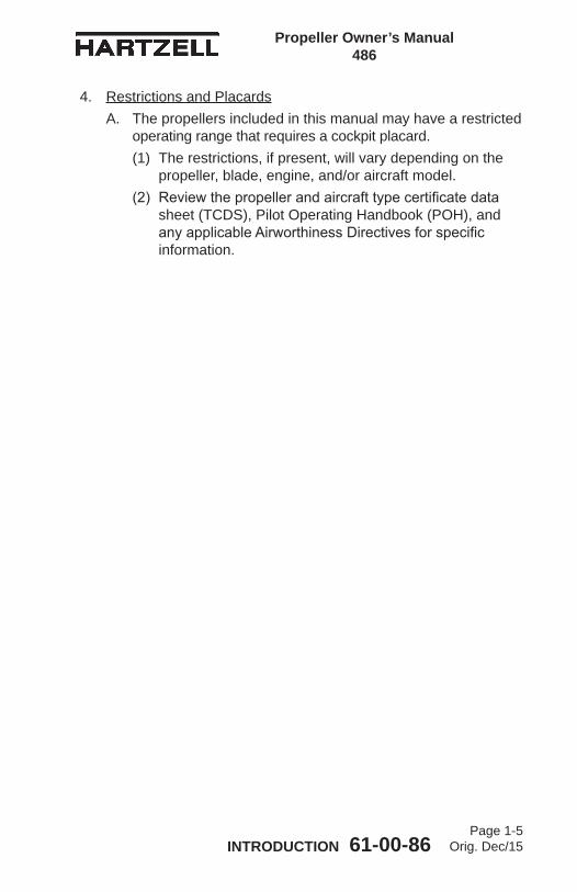
4. Restrictions and PlacardsA. The propellers included in this manual may have a restricted
operating range that requires a cockpit placard. (1) The restrictions, if present, will vary depending on the
propeller, blade, engine, and/or aircraft model. (2) Reviewthepropellerandaircrafttypecertificatedata
sheet (TCDS), Pilot Operating Handbook (POH), and anyapplicableAirworthinessDirectivesforspecificinformation.

Propeller Owner’s Manual 486
INTRODUCTION 61-00-86Page 1-6
Orig. Dec/15
5. GeneralA. Personnel Requirements
(1) Inspection, Repair, and Overhaul(a) Compliance to the applicable regulatory
requirements established by the Federal Aviation Administration (FAA) or foreign equivalent is mandatory for anyone performing or accepting responsibility for any inspection and/or repair and/or overhaul of any Hartzell Propeller Inc. product.
(b) Personnel performing maintenance on aluminum hub propellersareexpectedtohavesufficienttrainingandcertifications(whenrequiredbytheapplicableAviationAuthority) to accomplish the work required in a safe and airworthy manner
B. Maintenance Practices(1) The propeller and its components are highly vulnerable
to damage when they are removed from the engine. Properly protect all components until they are reinstalled on the engine.
(2) Never attempt to move the aircraft by pulling on the propeller.
(3) Avoid the use of blade paddles. Do not put the blade paddle in the area of the de-ice boot when applying torque to a blade assembly. Put the blade paddle in the thickest area of the blade, just outside of the de-ice boot. Use one blade paddle per blade
(4) Use only the approved consumables, e.g., cleaning agents, lubricants, etc.

Propeller Owner’s Manual 486
INTRODUCTION 61-00-86Page 1-7
Orig. Dec/15
(5) Safe Handling of Paints and Chemicals(a) Always use caution when handling or being exposed
to paints and/or chemicals during propeller overhaul and maintenance procedures.
(b) Before using paint or chemicals, always read the manufacturer’s label on the container and followspecifiedinstructionsandproceduresforstorage,preparation, mixing, and application.
(c) Refer to the product’s Material Safety Data Sheet (MSDS) for detailed information about physical properties, health, and physical hazards of any chemical.
(6) Observe applicable torque values during maintenance.(7) Approved paint must be applied to all composite blades.
For information about the application of paint, refer to the Maintenance Practices chapter of this manual. Operation ofbladeswithoutthespecifiedfinishesisnotpermitted.
(8) Before installing the propeller on the engine, the propeller must be statically balanced. New propellers are statically balanced at Hartzell Propeller Inc. Overhauled propellers must be statically balanced by the overhaul facility before return to service.(a) Dynamic balance is recommended, but may be
accomplished at the discretion of the operator, unlessspecificallyrequiredbytheairframeorenginemanufacturer. 1 Perform dynamic balance in accordance with the
Maintenance Practices chapter of this manual. 2 Additional procedures may be found in the
Aircraft Maintenance Manual.(9) As necessary, use a soft, non-graphite pencil, crayon,
or felt-tipped pen to make identifying marks on components.
(10) As applicable, follow military standard NASM33540 for safety-wire, safety cable, and cotter pin general practices. Use 0.032 inch (0.81 mm) stainless steel safety wire unless otherwise indicated.

Propeller Owner’s Manual 486
INTRODUCTION 61-00-86Page 1-8
Orig. Dec/15
WARNING: DO NOT USE OBSOLETE OR OUTDATED INFORMATION. PERFORM ALL INSPECTIONS OR WORK IN ACCORDANCE WITH THE MOST RECENT REVISION OF THIS MANUAL. INFORMATION CONTAINED IN THIS MANUAL MAY BE SIGNIFICANTLY CHANGED FROM EARLIER REVISIONS. USE OF OBSOLETE INFORMATION MAY RESULT IN DEATH, SERIOUS BODILY INJURY, AND/OR SUBSTANTIAL PROPERTY DAMAGE. FOR THE MOST RECENT REVISION LEVEL OF THIS MANUAL, REFER TO THE HARTZELL PROPELLER INC. WEBSITE AT WWW.HARTZELLPROP.COM.
(11) The information in this manual revision supersedes data in all previously published revisions of this manual.
(12) Refer to the airframe manufacturer’s manuals in addition to the information in this manual because of possible specialrequirementsforspecificaircraftapplications.
(13) If the propeller is equipped with an ice protection system that uses components supplied by Hartzell Propeller Inc., applicable instructions and technical information for the components supplied by Hartzell Propeller Inc. can be found in the following publications available on the Hartzell Propeller Inc. website at www.hartzellprop.com:(a) Hartzell Propeller Inc. Manual 180 (30-61-80) -
Propeller Ice Protection System Manual (b) Hartzell Propeller Inc. Manual 181 (30-60-81) -
Propeller Ice Protection System Component Maintenance Manual
(c) Hartzell Propeller Inc. Manual 182 (61-12-82) - Propeller Electrical De-Ice Boot Removal and Installation Manual
(d) Hartzell Propeller Inc. Manual 183 (61-12-83) - Propeller Anti-Icing Boot Removal and Installation Manual

Propeller Owner’s Manual 486
INTRODUCTION 61-00-86Page 1-9
Orig. Dec/15
(14) Propeller ice protection system components not supplied by Hartzell Propeller Inc. are controlled by the applicable TC or STC holder’s Instructions for Continued Airworthiness (ICA).
C. Continued Airworthiness(1) Operators are urged to keep informed of Airworthiness
information via Hartzell Propeller Inc. Service Bulletins and Service Letters, which are available from Hartzell distributors or from the Hartzell Propeller Inc. by subscription. Selected information is also available on the Hartzell Propeller Inc. website at www.hartzellprop.com.
D. Propeller Critical Parts(1) The following maintenance procedures may involve
propeller critical parts. These procedures have been substantiated based on Engineering analysis that expects this product will be operated and maintained using the procedures and inspections provided in the Instructions for Continued Airworthiness (ICA) for this product. Refer to the Illustrated Parts List chapter of the applicable maintenance manual for the applicable propellermodelfortheidentificationofspecificCriticalParts.
(2) Numerous propeller system parts can produce a propeller Major or Hazardous effect, even though those parts may not be considered as Critical Parts. The operating and maintenance procedures and inspections provided in the ICA for this product are, therefore, expected to be accomplished for all propeller system parts.

Propeller Owner’s Manual 486
INTRODUCTION 61-00-86Page 1-10
Orig. Dec/15
6. Reference PublicationsA. Hartzell Propeller Inc. Publications
Active Hartzell Propeller Inc. Service Bulletins, Letters, Instructions, and AdvisoriesHartzell Propeller Inc. Manual No. 127 (61-16-27) - Metal Spinner Assembly Maintenance Manual - Available on the Hartzell Propeller Inc. website at www.hartzellprop.comHartzell Propeller Inc. Manual No. 130B (61-23-30) - Mechanically Actuated Governor Maintenance ManualHartzell Propeller Inc. Manual No. 135F (61-13-35) - Composite Propeller Blade Maintenance ManualHartzell Propeller Inc. Manual No. 159 (61-02-59) - Application Guide - Available on the Hartzell Propeller Inc. website at www.hartzellprop.comHartzell Propeller Inc. Manual No. 165A (61-00-65) - Illustrated Tool and Equipment Manual - Available on the Hartzell Propeller Inc. website at www.hartzellprop.comHartzell Propeller Inc. Manual No. 170 (61-13-70) - Composite Propeller Blade Field Maintenance and Minor Repair Manual - Available on the Hartzell Propeller Inc. website at www.hartzellprop.comHartzell Propeller Inc. Manual No. 173 (61-10-73) - Composite spinner Field Maintenance and Minor Repair Manual - Available on the Hartzell Propeller Inc. website at www.hartzellprop.com
Hartzell Propeller Inc. Manual No. 180 (30-61-80) - Propeller Ice Protection System Manual - Available on the Hartzell Propeller Inc. website at www.hartzellprop.comHartzell Propeller Inc. Manual No. 181 (30-60-81) - Propeller Ice Protection System Component Maintenance Manual - Available on the Hartzell Propeller Inc. website at www.hartzellprop.com
Hartzell Propeller Inc. Manual No. 182 (61-12-82) - Propeller Electrical De-ice Boot Removal and Installation Manual - Available on the Hartzell Propeller Inc. website at www.hartzellprop.com

Propeller Owner’s Manual 486
INTRODUCTION 61-00-86Page 1-11
Orig. Dec/15
Hartzell Propeller Inc. Manual No. 183 (61-12-83) - Propeller Anti-icing Boot Removal and Installation Manual - Available on the Hartzell Propeller Inc. website at www.hartzellprop.comHartzell Propeller Inc. Manual No. 496 (61-10-96) - Five Blade Raptor Turbine Propeller Maintenance ManualHartzell Propeller Inc. Manual No. 202A (61-01-02) - Standard Practices Manual, Volumes 1 through 11 - Volume 7 - Consumable Materials is available on the Hartzell Propeller Inc. website at www.hartzellprop.com.Hartzell Propeller Inc. Service Letter HC-SL-61-61Y - Propeller Overhaul Periods and Service Life Limits for Hartzell Propeller Inc. Aviation components - Propellers, governors, Accumulators, and Propeller Damper Assemblies - Available on the Hartzell Propeller Inc. website at www.hartzellprop.com

Propeller Owner’s Manual 486
INTRODUCTION 61-00-86Page 1-12
Orig. Dec/15
B. References to Hartzell Propeller Inc. Publications(1) Special tooling is required for procedures throughout
this manual. For further tooling information, refer to Hartzell Propeller Inc. Illustrated Tool and Equipment Manual 165A (61-00-65). (a) Toolingreferencesappearwiththeprefix“TE”
directly following the tool name to which they apply. For example, a template which is reference number 133 will appear as: template TE133.
(2) Consumable materials are referenced in certain sectionsthroughoutthismanual.Specificapprovedmaterials are listed in the Consumable Materials chapter of Hartzell Propeller Inc. Standard Practices Manual 202A (61-01-02).(a) The reference number for consumable materials
appearwiththeprefix“CM”directlyfollowingthematerial to which they apply. For example, an approved adhesive that is reference number 16 will appear as: approved adhesive CM16. Only those itemsspecifiedmaybeused.
Propeller Owner’s Manual 486
INTRODUCTION 61-00-86Page 1-13
Orig. Dec/15
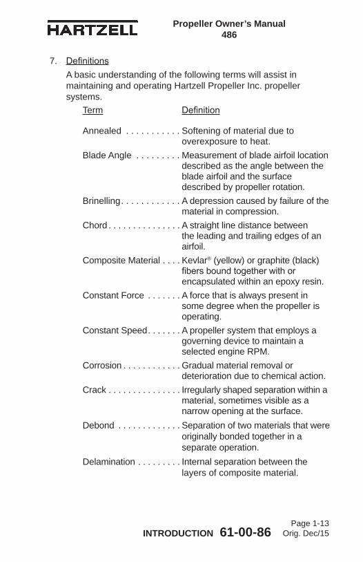
7. DefinitionsA basic understanding of the following terms will assist in maintaining and operating Hartzell Propeller Inc. propeller systems.
Term Definition
Annealed . . . . . . . . . . . Softening of material due to overexposure to heat.
Blade Angle . . . . . . . . . Measurement of blade airfoil location described as the angle between the blade airfoil and the surface described by propeller rotation.
Brinelling . . . . . . . . . . . . A depression caused by failure of the material in compression.
Chord . . . . . . . . . . . . . . . A straight line distance between the leading and trailing edges of an airfoil.
Composite Material . . . . Kevlar® (yellow) or graphite (black) fibersboundtogetherwithorencapsulated within an epoxy resin.
Constant Force . . . . . . . A force that is always present in some degree when the propeller is operating.
Constant Speed . . . . . . . A propeller system that employs a governing device to maintain a selected engine RPM.
Corrosion . . . . . . . . . . . . Gradual material removal or deterioration due to chemical action.
Crack . . . . . . . . . . . . . . . Irregularly shaped separation within a material, sometimes visible as a narrow opening at the surface.
Debond . . . . . . . . . . . . . Separation of two materials that were originally bonded together in a separate operation.
Delamination . . . . . . . . . Internal separation between the layers of composite material.

Propeller Owner’s Manual 486
INTRODUCTION 61-00-86Page 1-14
Orig. Dec/15
Depression . . . . . . . . . . Surface area where the material has been compressed but not removed.
Distortion . . . . . . . . . . . Alteration of the original shape or size of a component.
Erosion . . . . . . . . . . . . . Gradual wearing away or deterioration due to action of the elements.
Exposure . . . . . . . . . . . Material open to action of the elements.
Feathering . . . . . . . . . . The capability of blades to be rotated parallel to the relative wind, thus reducing aerodynamic drag.
Fretting . . . . . . . . . . . . . Damage that develops when relative motion of small displacement takes place between contacting parts, wearing away the surface.
Gouge . . . . . . . . . . . . . . Surface area where material has been removed.
Hazardous PropellerEffect . . . . . . . . . . . . . . The hazardous propeller effects
aredefinedinTitle14CFRsection35.15(g)(1).
Horizontal Balance . . . . Balance between the blade tip and the center of the hub.
Impact Damage . . . . . . Damage that occurs when the propeller blade or hub assembly strikes, or is struck by, an object whileinflightorontheground.
Major Propeller Effect . . The major propeller effects are definedinTitle14CFRsection35.15(g)(2).
Nick . . . . . . . . . . . . . . . Removal of paint and possibly a small amount of material.
Term Definition

Propeller Owner’s Manual 486
INTRODUCTION 61-00-86Page 1-15
Orig. Dec/15
Onspeed . . . . . . . . . . . . Condition in which the RPM selected by the pilot through the propeller control lever and the actual engine (propeller) RPM are equal.
Overhaul . . . . . . . . . . . . The periodic disassembly, inspection,repair,refinish,andreassembly of a propeller assembly to maintain airworthiness.
Overspeed . . . . . . . . . . Condition in which the RPM of the propeller or engine exceeds predetermined maximum limits; the condition in which the engine (propeller) RPM is higher than the RPM selected by the pilot through the propeller control lever.
Overspeed Damage . . . Damage that occurs when the propeller hub assembly rotates at a speed greater than the maximum limit for which it is designed.
Pitch . . . . . . . . . . . . . . . Sameas“BladeAngle”.Pitting . . . . . . . . . . . . . . Formation of a number of small,
irregularly shaped cavities in surface material caused by corrosion or wear.
Propeller Critical Part . .A part on the propeller whose primary failure can result in a hazardous propeller effect, as determined by the safety analysis required by Title 14 CFR section 35.15.
Reversing . . . . . . . . . . . The capability of rotating blades to a position to generate reverse thrust to slow the aircraft or back up.
Scratch . . . . . . . . . . . . . Sameas“Nick”.Single Acting . . . . . . . . . Hydraulically actuated propeller that
utilizes a single oil supply for pitch control.
Term Definition

Propeller Owner’s Manual 486
INTRODUCTION 61-00-86Page 1-16
Orig. Dec/15
Split . . . . . . . . . . . . . . . . Delamination of blade extending to the blade surface, normally found near the trailing edge or tip.
Synchronizing . . . . . . . . Adjusting the RPM of all the propellers of a multi-engine aircraft to the same RPM.
Synchrophasing . . . . . . A form of propeller sychronization in which not only the RPM of the engines (propellers) are held constant, but also the position of the propellers in relation to each other.
Track . . . . . . . . . . . . . . . In an assembled propeller, a measurement of the location of the blade tip with respect to the plane of rotation, in order to compare blade tip location with respect to the locations of the other blades in the assembly.
Underspeed . . . . . . . . . The condition in which the actual engine (propeller) RPM is lower than the RPM selected by the pilot through the propeller control lever.
Variable Force . . . . . . . A force that may be applied or removed during propeller operation.
Vertical Balance . . . . . . Balance between the leading and trailing edges of a two-blade propeller with the blades positioned vertically.
Windmilling . . . . . . . . . . The rotation of an aircraft propeller causedbyairflowingthroughitwhilethe engine is not producing power.
Term Definition

Propeller Owner’s Manual 486
INTRODUCTION 61-00-86Page 1-17
Orig. Dec/15
8. Abbreviations
Abbreviation Term
AMM . . . . . . . . . . . . . . . Aircraft Maintenance ManualAN . . . . . . . . . . . . . . . . . Air Force-Navy (or Army-Navy)AOG . . . . . . . . . . . . . . . Aircraft on GroundFAA . . . . . . . . . . . . . . . . Federal Aviation AdministrationFt-Lb . . . . . . . . . . . . . . . Foot-PoundICA . . . . . . . . . . . . . . . . Instructions for Continued
AirworthinessID . . . . . . . . . . . . . . . . . Inside DiameterIn-Lb . . . . . . . . . . . . . . . Inch-PoundLbs . . . . . . . . . . . . . . . . Pounds MIL-X-XXX . . . . . . . . . . MilitarySpecificationMPI . . . . . . . . . . . . . . . . Major Periodic InspectionMS . . . . . . . . . . . . . . . . Military StandardMSDS . . . . . . . . . . . . . . Material Safety Data SheetNAS . . . . . . . . . . . . . . . National Aerospace Standards NASM . . . . . . . . . . . . . . National Aerospace Standards,
MilitaryN•m . . . . . . . . . . . . . . . . Newton-MetersOD . . . . . . . . . . . . . . . . Outside DiameterPOH . . . . . . . . . . . . . . . Pilot’s Operating HandbookPSI . . . . . . . . . . . . . . . . Pounds per Square Inch RPM . . . . . . . . . . . . . . . Revolutions per MinuteSTC . . . . . . . . . . . . . . . SupplementalTypeCertificateTBO . . . . . . . . . . . . . . . Time Between OverhaulTC . . . . . . . . . . . . . . . . . TypeCertificateTSN . . . . . . . . . . . . . . . Time Since NewTSO . . . . . . . . . . . . . . . Time Since Overhaul
NOTE: TSN/TSO is considered as the time accumulated betweenrotationandlanding,i.e.,flighttime.
Propeller Owner’s Manual 486
INTRODUCTION 61-00-86Page 1-18
Orig. Dec/15
9. Hartzell Propeller Inc. Product SupportA. Hartzell Propeller Inc. is ready to assist you with questions
about your propeller system. Hartzell Propeller Inc. product support may be reached during business hours (8:00 am through 5:00 pm, United States Eastern Time) at (937) 778-4379 or at (800) 942-7767, toll free from the United States and Canada. Hartzell Propeller Inc. Product Support can also be reached by fax at (937) 778-4215, and by e-mail at [email protected].
B. After business hours, you may leave a message on our 24 hour product support line at (937) 778-4376 or at (800) 942-7767, toll free from the United States and Canada. A technical representative will contact you during normal business hours. Urgent AOG support is also available 24 hours per day, seven days per week via this message service.
C. Additional information is available on the Hartzell Propeller Inc. website at www.hartzellprop.com
NOTE: When calling from outside the United States, dial (001) before dialing the above telephone numbers.
10. Warranty ServiceIf you believe you have a warranty claim, it is necessary to contact the Hartzell Propeller Inc. Warranty Administrator. The Hartzell Propeller Inc. Warranty Administrator will provide a blank Warranty Application form. It is necessary to complete this form and return it to the Warranty Administrator for evaluation before proceeding with repair or inspection work. Upon receipt of this form, the Warranty Administrator will provide instructions on how to proceed. Hartzell Propeller Inc. Warranty may be reached during business hours (8:00 am through 5:00 pm, United States Eastern Time) at (937) 778-4380, or toll free from the United States and Canada at (800) 942-7767. Hartzell Propeller Inc. Warranty Adminstration can also be reached by fax, at (937) 778-4215, or by e-mail at [email protected]: When calling from outside the United States, dial (001)
before dialing the above telephone numbers.

Propeller Owner’s Manual 486
INTRODUCTION 61-00-86Page 1-19
Orig. Dec/15
11. Hartzell Propeller Inc. Recommended FacilitiesA. Hartzell Propeller Inc. recommends using Hartzell
Propeller Inc. approved distributors and repair facilities for the purchase, repair and overhaul of Hartzell Propeller Inc.propeller assemblies or components.
B. Information about the Hartzell Propeller Inc. worldwide network of aftermarket distributors and approved repair facilities is available on the Hartzell Propeller Inc. website at www.hartzellprop.com.

Propeller Owner’s Manual 486
INTRODUCTION 61-00-86Page 1-20
Orig. Dec/15
(This page is intentionally blank.)

Propeller Owner’s Manual 486
DESCRIPTION AND OPERATION 61-00-86Page 2-1
Orig. Dec/15
DESCRIPTION AND OPERATION - CONTENTS
LIST OF FIGURES
Propeller Flange Description ........................Figure 2-1 ............. 2-6
Governor in Onspeed Condition ....................Figure 2-7 ........... 2-10
Governor in Underspeed Condition ...............Figure 2-8 ........... 2-10
Governor in Overspeed Condition .................Figure 2-9 ........... 2-10
Propeller Model Designations........................Table 2-1 .............. 2-8
Blade Type and Blade Model Designations ...Table 2-2 .............. 2-9
LIST OF TABLES
1. Functional Description of Constant Speed Propeller Types ... 2-3A. Feathering and Reversing Propellers ( )D3-( )( )( ) Series ........................................................... 2-3
2. Model Designation .................................................................. 2-7
3. Governors ............................................................................. 2-11A. Theory of Operation ......................................................... 2-11B. Governor Types ............................................................... 2-13C.IdentificationofHartzellPropellerInc.Governors ............ 2-13
4. Propeller Ice Protection Systems ......................................... 2-14A. Propeller Anti-ice System ................................................. 2-14B. Propeller De-ice System .................................................. 2-15

Propeller Owner’s Manual 486
DESCRIPTION AND OPERATION 61-00-86Page 2-2
Orig. Dec/15
(This page is intentionally blank.)

Propeller Owner’s Manual 486
DESCRIPTION AND OPERATION 61-00-86Page 2-3
Orig. Dec/15
1. Functional Description of Constant Speed Propeller TypesA. Feathering and Reversing Propellers ( )D3-( )( )( ) Series
The propellers described in this section are constant speed, feathering and reversing. They use a single oil supply from a governing device to hydraulically actuate a change in bladeangle.Thepropellershavefivebladesandareusedprimarily on Pratt & Whitney turbine engines.A two piece aluminum hub retains each propeller blade on a thrust bearing. A cylinder is attached to the hub and contains a feathering spring and piston. The hydraulically actuated piston transmits linear motion through a pitch change rod and fork to each blade to result in blade angle change. While the propeller is operating the following forces are constantly present: 1) spring force, 2) counterweight force, 3) centrifugal twisting moment of each blade and 4) blade aerodynamic twisting forces. The spring and counterweight forces attempt to rotate the blades to higher blade angle while the centrifugal twisting moment of each blade is generally toward lower blade angle. Blade aerodynamic twisting force is generally very small in relation to the other forces and can attempt to increase or decrease blade angle. Summation of the propeller forces is toward higher pitch (low RPM) and is opposed by a variable force toward lower pitch (high RPM). The variable force is oil under pressure from a governor with an internal pump that is mounted on and driven by the engine. The oil from the governor is supplied to the propeller and hydraulic piston through a hollow engine shaft. Increasing the volume of oil within the piston and cylinder will decrease the blade angle and increase propeller RPM. Decreasing the volume of oil will increase blade angle and decrease propeller RPM. By changing the blade angle, the governor can vary the load on the engine and maintain constant engine RPM (within limits), independent of where the power lever is set. The governor uses engine speed sensing mechanisms that permit it to supply or drain oil as necessary to maintain constant engine speed (RPM).
Propeller Owner’s Manual 486
DESCRIPTION AND OPERATION 61-00-86Page 2-4
Orig. Dec/15
If governor supplied oil is lost during operation, the propeller will increase pitch and feather. Feathering occurs because the summation of internal propeller forces causes the oil to drain out of the propeller until the feather stop position is reached. Normalin-flightfeatheringisaccomplishedwhenthepilotretards the propeller condition lever past the feather detent. This permits control oil to drain from the propeller and return to the engine sump. Engine shutdown is normally accomplished during the feathering process.Normalin-flightunfeatheringisaccomplishedwhenthepilotpositionsthepropellerconditionleverintothenormalflight(governing) range and restarts the engine. As engine speed increases, the governor supplies oil to the propeller and the blade angle decreases.In reverse mode of operation the governor operates in an underspeed condition to act strictly as a source of pressurizedoil,withoutattemptingtocontrolRPM.Controlofthe propeller blade angle in reverse is accomplished with the beta valve.NOTE: The beta valve is normally built into the base of the
governor.The propeller is reversed by manually repositioning the cockpit-control to cause the beta valve to supply oil from the governor pump to the propeller. Several external propeller mechanisms, which include a beta ring and beta feedback block assembly, communicate propeller blade angle position to the beta valve. When the propeller reaches the desired reverse position, movement of the beta ring and beta feedback block assembly initiated by the propeller piston, causes the beta valve to shut offtheflowofoiltothepropeller.Anyadditionalunwantedmovement of the propeller toward reverse, or any movement of the manually positioned beta valve control toward high pitch position will cause the beta valve to drain oil from the propeller to increase pitch.
Propeller Owner’s Manual 486
DESCRIPTION AND OPERATION 61-00-86Page 2-5
Orig. Dec/15
If governor supplied oil is lost during operation, the propeller will increase pitch and feather. Feathering occurs because the summation of internal propeller forces causes the oil to drain out of the propeller until the feather stop position is reached. Normalin-flightfeatheringisaccomplishedwhenthepilotretards the propeller condition lever past the feather detent. This permits control oil to drain from the propeller and return to the engine sump. Engine shutdown is normally accomplished during the feathering process.Normalin-flightunfeatheringisaccomplishedwhenthepilotpositionsthepropellerconditionleverintothenormalflight(governing) range and restarts the engine. As engine speed increases, the governor supplies oil to the propeller and the blade angle decreases.

Propeller Owner’s Manual 486
DESCRIPTION AND OPERATION 61-00-86Page 2-6
Orig. Dec/15
Propeller Flange Description Figure 2-1
N Flange
Dowel PinHole
Dowel PinHole
Bolt Circle No. of Dowels No. of Bolts Typical Engine
4.25 inch 4 (0.50 inch)
8 (9/16 inch)
Pratt & Whitney (Refer to NOTE)
NOTE: AnNflangepropellercanbeusedonanenginethat has 2 dowel pins or 4 dowel pins.

Propeller Owner’s Manual 486
DESCRIPTION AND OPERATION 61-00-86Page 2-7
Orig. Dec/15
2. Model DesignationThe following pages illustrate sample model designations for HartzellPropellerInc.propellerhubassembliesandblades.A. Refer to Table 2-1 for the propeller model designations for
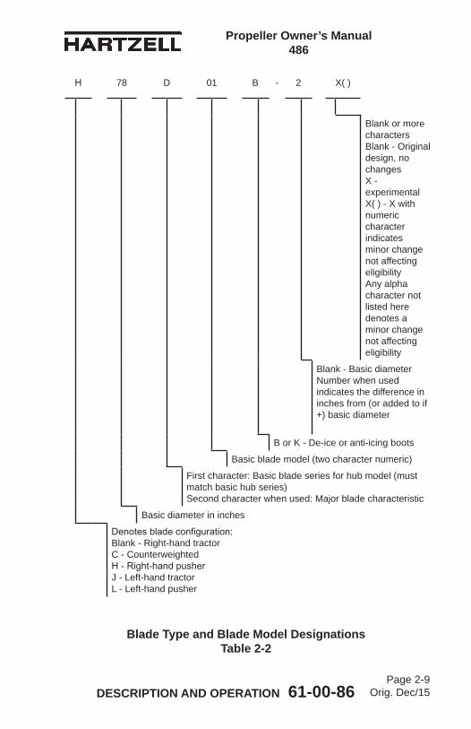
HartzellPropellerInc.Raptorseriespropellers.B. RefertoTable2-2forCompositeBladeModelIdentification.
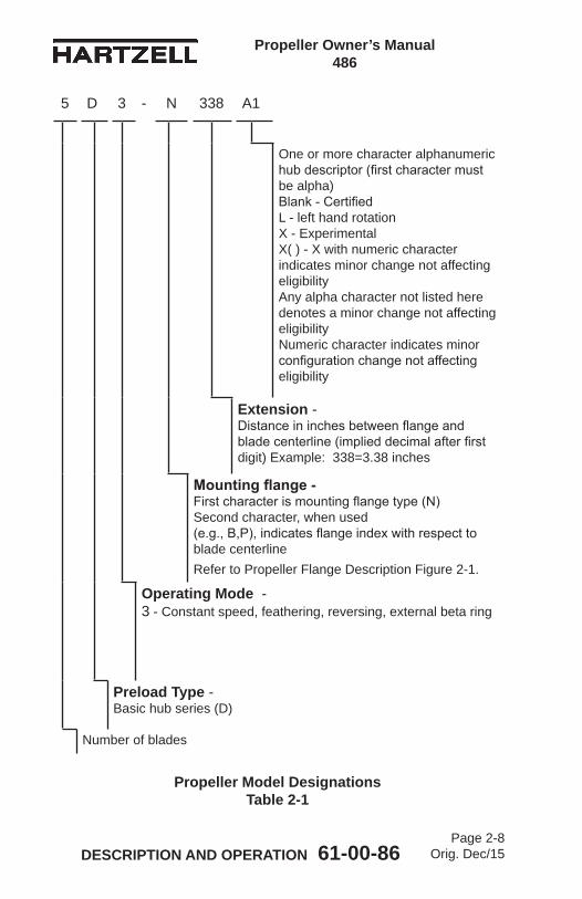
(1) HartzellPropellerInc.usesamodeldesignationtoidentifyspecificpropellerandbladeassemblies.Example: 5D3-N338A1/78D01B.
(2) A slash mark separates the propeller and blade designations. The propeller model designation is impression stamped on the propeller hub. The blade designation is impression stamped on the blade butt end (internal) and may be on a label on the propeller cylinder (external).
Propeller Owner’s Manual 486
DESCRIPTION AND OPERATION 61-00-86Page 2-8
Orig. Dec/15
Propeller Model Designations Table 2-1
5 D 3 - N 338 A1
One or more character alphanumeric hubdescriptor(firstcharactermustbe alpha) Blank-Certified L - left hand rotation X - Experimental X( ) - X with numeric character indicates minor change not affecting eligibility Any alpha character not listed here denotes a minor change not affecting eligibility Numeric character indicates minor configurationchangenotaffectingeligibility
Extension - Distanceininchesbetweenflangeandbladecenterline(implieddecimalafterfirstdigit) Example: 338=3.38 inches
Mounting flange - Firstcharacterismountingflangetype(N) Second character, when used (e.g.,B,P),indicatesflangeindexwithrespecttoblade centerlineRefer to Propeller Flange Description Figure 2-1.
Operating Mode - 3 - Constant speed, feathering, reversing, external beta ring
Preload Type - Basic hub series (D)
Number of blades
Propeller Owner’s Manual 486
DESCRIPTION AND OPERATION 61-00-86Page 2-9
Orig. Dec/15
Blade Type and Blade Model Designations Table 2-2
H 78 D 01 B - 2 X( )
Blank or more characters Blank - Original design, no changes X - experimental X( ) - X with numeric character indicates minor change not affecting eligibility Any alpha character not listed here denotes a minor change not affecting eligibility
Blank - Basic diameter Number when used indicates the difference in inches from (or added to if +) basic diameter
B or K - De-ice or anti-icing boots
Basic blade model (two character numeric)
First character: Basic blade series for hub model (must match basic hub series) Second character when used: Major blade characteristic
Basic diameter in inches
Denotesbladeconfiguration: Blank - Right-hand tractor C - Counterweighted H-Right-handpusher J - Left-hand tractor L - Left-hand pusher

Propeller Owner’s Manual 486
DESCRIPTION AND OPERATION 61-00-86Page 2-10
Orig. Dec/15
Governor in Onspeed Condition Figure 2-7
Governor in Underspeed Condition Figure 2-8
Governor in Overspeed Condition Figure 2-9
Pilot Control
Speeder SpringFlyweights
Pilot Valve
Pilot Control
Speeder SpringFlyweights
Pilot Valve
Pilot Control
Speeder SpringFlyweights
Pilot Valve
AP
S61
49A
PS
6150
AP
S61
51
Propeller Owner’s Manual 486
DESCRIPTION AND OPERATION 61-00-86Page 2-11
Orig. Dec/15
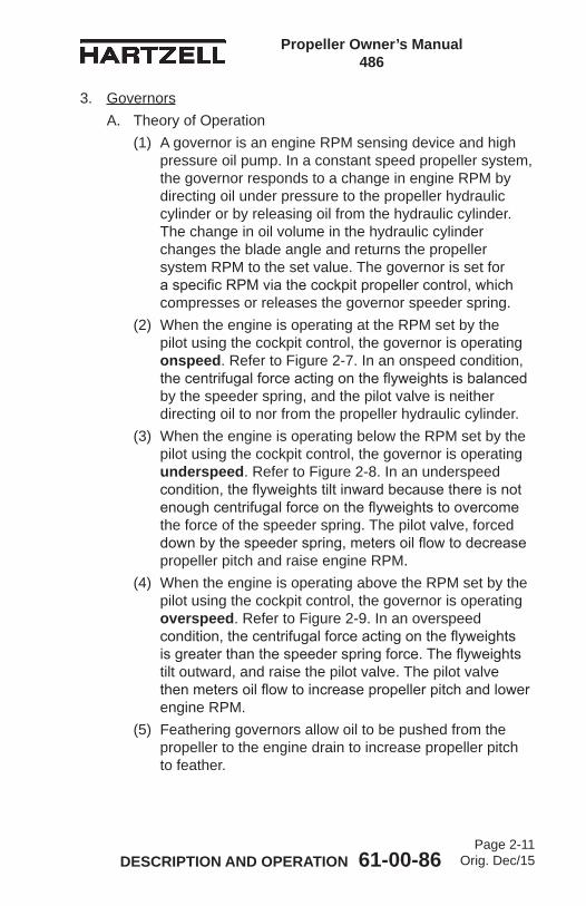
3. GovernorsA. Theory of Operation
(1) A governor is an engine RPM sensing device and high pressure oil pump. In a constant speed propeller system, the governor responds to a change in engine RPM by directing oil under pressure to the propeller hydraulic cylinder or by releasing oil from the hydraulic cylinder. The change in oil volume in the hydraulic cylinder changes the blade angle and returns the propeller system RPM to the set value. The governor is set for aspecificRPMviathecockpitpropellercontrol,whichcompresses or releases the governor speeder spring.
(2) When the engine is operating at the RPM set by the pilot using the cockpit control, the governor is operating onspeed. Refer to Figure 2-7. In an onspeed condition, thecentrifugalforceactingontheflyweightsisbalancedby the speeder spring, and the pilot valve is neither directing oil to nor from the propeller hydraulic cylinder.
(3) When the engine is operating below the RPM set by the pilot using the cockpit control, the governor is operating underspeed. Refer to Figure 2-8. In an underspeed condition,theflyweightstiltinwardbecausethereisnotenoughcentrifugalforceontheflyweightstoovercomethe force of the speeder spring. The pilot valve, forced downbythespeederspring,metersoilflowtodecreasepropeller pitch and raise engine RPM.
(4) When the engine is operating above the RPM set by the pilot using the cockpit control, the governor is operating overspeed. Refer to Figure 2-9. In an overspeed condition,thecentrifugalforceactingontheflyweightsisgreaterthanthespeederspringforce.Theflyweightstilt outward, and raise the pilot valve. The pilot valve thenmetersoilflowtoincreasepropellerpitchandlowerengine RPM.
(5) Feathering governors allow oil to be pushed from the propeller to the engine drain to increase propeller pitch to feather.

Propeller Owner’s Manual 486
DESCRIPTION AND OPERATION 61-00-86Page 2-12
Orig. Dec/15
(6) Asynchronizingsystemcanbeemployedina multi-engine aircraft to keep the engines operating at the same RPM. A synchrophasing system not only keeps RPM of the engines consistent, but also keeps the propeller blades operating in phase with each other. Bothsynchronizingandsynchrophasingsystemsserveto reduce noise and vibration.

Propeller Owner’s Manual 486
DESCRIPTION AND OPERATION 61-00-86Page 2-13
Orig. Dec/15
B. Governor TypesThegovernorscommonlyusedinHartzellPropellerInc.propellersystemsaresuppliedeitherbyHartzellPropellerInc. or several another manufacturers. These governor types function in a similar manner.
C. IdentificationofHartzellPropellerInc.GovernorsAHartzellPropellerInc.governormaybeidentifiedbymodelnumber as follows:
NOTE: For maintenance and overhaul instructions for HartzellPropellerInc.governors,refertoHartzellPropeller Inc. Mechanically Actuated Governor Maintenance Manual 130B (61-23-30).
(X) - (X) - (X)
Minor variation of basic design. (Numeric and/or alpha character)
Specificmodelapplication (numeric character) - special attributes
Basic Body and Major Parts Modification(alphacharacter)

Propeller Owner’s Manual 486
DESCRIPTION AND OPERATION 61-00-86Page 2-14
Orig. Dec/15
4. Propeller Ice Protection SystemsA. Propeller Anti-ice System
(1) A propeller anti-ice system is a system that prevents ice from forming on propeller surfaces. The system dispensesananti-icingfluid(usuallyisopropylalcohol)which mixes with moisture on the propeller blades, reducingthefreezingpointofthewater.The water/alcoholmixtureflowsoffofthebladesbefore ice forms. This system must be in use before ice forms. It is ineffective in removing ice that has already formed.(a) System Overview
1 Atypicalanti-icesystemconsistsofafluidtank,pump, and distribution tubing.
2 Therateatwhichtheanti-icingfluidisdispensedis controlled by a pump speed rheostat in the cockpit.
3 Theanti-icingfluidisdispensedthroughairframemounted distribution tubing and into a rotating slinger ring mounted on the rear of the propeller hub.Theanti-icingfluidisthendirectedthroughblade feed tubes from the slinger ring onto the bladesviacentrifugalforce.Theanti-icingfluidisdirected onto anti-icing boots that are attached to the leading edge of the blade. These anti-icing bootsevenlydistributeanddirectthefluidalongthe blade leading edge.
Propeller Owner’s Manual 486
DESCRIPTION AND OPERATION 61-00-86Page 2-15
Orig. Dec/15
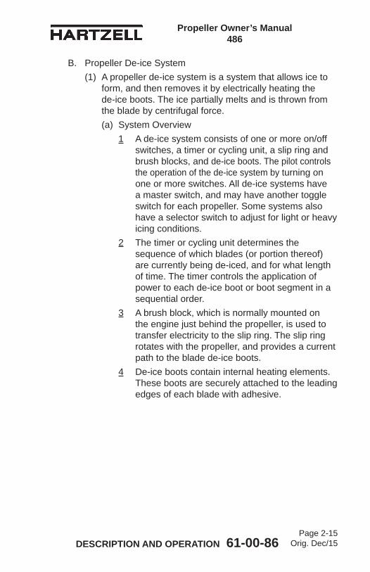
B. Propeller De-ice System(1) A propeller de-ice system is a system that allows ice to
form, and then removes it by electrically heating the de-ice boots. The ice partially melts and is thrown from the blade by centrifugal force.(a) System Overview
1 A de-ice system consists of one or more on/off switches, a timer or cycling unit, a slip ring and brush blocks, and de-ice boots. The pilot controls the operation of the de-ice system by turning on one or more switches. All de-ice systems have a master switch, and may have another toggle switch for each propeller. Some systems also have a selector switch to adjust for light or heavy icing conditions.
2 The timer or cycling unit determines the sequence of which blades (or portion thereof) are currently being de-iced, and for what length of time. The timer controls the application of power to each de-ice boot or boot segment in a sequential order.
3 A brush block, which is normally mounted on the engine just behind the propeller, is used to transfer electricity to the slip ring. The slip ring rotates with the propeller, and provides a current path to the blade de-ice boots.
4 De-ice boots contain internal heating elements. These boots are securely attached to the leading edges of each blade with adhesive.

Propeller Owner’s Manual 486
DESCRIPTION AND OPERATION 61-00-86Page 2-16
Orig. Dec/15
(This page is intentionally blank.)

Propeller Owner’s Manual 486
INSTALLATION AND REMOVAL 61-00-86Page 3-1
Orig. Dec/15
INSTALLATION AND REMOVAL - CONTENTS 1. Tools, Consumables, and Expendables ................................. 3-3
A. Tooling ................................................................................ 3-3B. Consumables ..................................................................... 3-3C. Expendables ...................................................................... 3-3
2. Pre-Installation ........................................................................ 3-4A. Inspection of Shipping Package ......................................... 3-4B. Uncrating ............................................................................ 3-4C. Inspection after Shipment .................................................. 3-4D. Reassembly of a Propeller Disassembled for Shipment .... 3-4
3. Propeller Assembly Installation ............................................... 3-5A. Precautions ........................................................................ 3-5B. Installing ( )D3-( )( )( ) Propeller on the Aircraft Engine ...... 3-9
4. Spinner Installation ............................................................... 3-21
5. Post-Installation Checks ....................................................... 3-28
6. Spinner Removal .................................................................. 3-29
7. Propeller Removal ................................................................ 3-29A. Removal of ( )D3-( )( )( ) Propellers ................................. 3-29
Propeller Owner’s Manual 486
INSTALLATION AND REMOVAL 61-00-86Page 3-2
Orig. Dec/15
LIST OF FIGURES Tool for Decompressing ( )D3-( )( )( ) Series
External Beta System ................................... Figure 3-1 .......3-8Installing Propeller on Engine Flange .................. Figure 3-2 .....3-12Mounting Bolt and Washer .................................. Figure 3-3 .....3-13Determining Torque Value When Using
Torquing Adapter ........................................... Figure 3-4 .....3-14Diagram of Torquing Sequence
for Propeller Mounting Bolts .......................... Figure 3-5 .....3-15Beta Feedback Block Assembly
and Beta Ring Clearance .............................. Figure 3-6 .....3-16Beta Feedback Block Assembly .......................... Figure 3-7 .....3-16Resistance Check Locations ............................... Figure 3-8 .....3-20Resistance Check of the Dome ........................... Figure 3-9 .....3-22Spinner Assembly ............................................... Figure 3-10 ...3-24Spinner Reassembly Procedures ........................ Figure 3-11 ....3-25Optional Tape on the Forward Bulkhead ............. Figure 3-12 ...3-26
LIST OF TABLES Propeller/Engine Flange O-rings
and Mounting Hardware ................................ Table 3-1 .......3-10Torque Table ........................................................ Table 3-2 ....... 3-11Resistance Checks .............................................. Table 3-3 .......3-21

Propeller Owner’s Manual 486
INSTALLATION AND REMOVAL 61-00-86Page 3-3
Orig. Dec/15
1. Tools, Consumables, and ExpendablesThe following tools, consumables, and expendables will be required for propeller removal or installation:NOTE: TheflangetypeusedonaparticularRaptorpropeller
installation is indicated in the propeller model identificationnumberstampedonthehub.Forexample,5D3-N338-()indicatesanNflange.RefertoAluminumHubModelIdentificationintheDescriptionandOperationchapterofthismanualfordescriptionofeachflange type.
A. ToolingN Flange Propellers • Safety wire pliers (Alternate: Safety cable tool) • Torque wrench • Torque wrench adapter (Hartzell Propeller Inc. P/N AST-2877 or P/N AST-2877-1 as applicable)
B. Consumables• Quick Dry Stoddard Solvent or Methyl-Ethyl-Ketone (MEK)• Loctite 222 low strength threadlocker
C. Expendables• 0.032 inch (0.81 mm) stainless steel aircraft safety wire (Alternate: 0.032 inch [0.81 mm] aircraft safety cable and associated washers and ferrules) • O-ring, Propeller-to-Engine Seal (see Table 3-1)
Propeller Owner’s Manual 486
INSTALLATION AND REMOVAL 61-00-86Page 3-4
Orig. Dec/15
2. Pre-InstallationA. Inspection of Shipping Package
(1) Examine the exterior of the shipping container for signs of shipping damage.(a) A hole, tear or crushed appearance at the end of
the box (blade tips) may indicate that the propeller was dropped during shipment, possibly damaging the blades.
B. Uncrating(1) Putthepropelleronafirmsupport.(2) Remove the banding and any external wood bracing from
the shipping container. (3) Remove the cardboard from the hub and blades.
CAUTION: DO NOT STAND THE PROPELLER ON A BLADE TIP.
(4) Put the propeller on a padded surface that supports the propeller over a large area.
(5) Remove the plastic dust cover cup from the propeller mountingflange(ifinstalled).
C. Inspection after Shipment(1) After removing the propeller from the shipping container,
examine the propeller components for shipping damage.D. Reassembly of a Propeller Disassembled for Shipment
(1) If a propeller was received disassembled for shipment, it is to be reassembled by trained personnel in accordance with the applicable propeller maintenance manual.

Propeller Owner’s Manual 486
INSTALLATION AND REMOVAL 61-00-86Page 3-5
Orig. Dec/15
3. Propeller Assembly Installation
CAUTION: INSTRUCTIONS AND PROCEDURES IN THIS SECTION MAY INVOLVE PROPELLER CRITICAL PARTS. REFER TO THE INTRODUCTION CHAPTER OF THIS MANUAL FOR INFORMATION ABOUT PROPELLER CRITICAL PARTS. REFER TO THE ILLUSTRATED PARTS LIST CHAPTER OF THE APPLICABLE OVERHAUL MANUAL(S) FOR THE IDENTIFICATION OF SPECIFIC PROPELLER CRITICAL PARTS.
A. Precautions
WARNING 1: DURING ENGINE INSTALLATION OR REMOVAL, USING THE PROPELLER TO SUPPORT THE WEIGHT OF THE ENGINE IS NOT AUTHORIZED. UNAPPROVED INSTALLATION AND REMOVAL TECHNIQUES MAY CAUSE DAMAGE TO THE PROPELLER, THAT MAY LEAD TO FAILURE RESULTING IN AN AIRCRAFT ACCIDENT.
WARNING 2: WHEN INSTALLING THE PROPELLER, FOLLOW THE AIRFRAME MANUFACTURER’S MANUALS AND PROCEDURES, AS THEY MAY CONTAIN ISSUES VITAL TO AIRCRAFT SAFETY THAT ARE NOT CONTAINED IN THIS OWNER’S MANUAL.
CAUTION: AVOID THE USE OF BLADE PADDLES. DO NOT PUT THE BLADE PADDLE IN THE AREA OF THE DE-ICE BOOT WHEN APPLYING TORQUE TO A BLADE ASSEMBLY. PUT THE BLADE PADDLE IN THE THICKEST AREA OF THE BLADE, JUST OUTSIDE OF THE DE-ICE BOOT. USE ONE BLADE PADDLE PER BLADE.
(1) Make sure the propeller is removed before the engine is removed or installed in the airframe.

Propeller Owner’s Manual 486
INSTALLATION AND REMOVAL 61-00-86Page 3-6
Orig. Dec/15
(2) Follow the airframe manufacturer’s instructions for installing the propeller. (a) If such instructions are not in the airframe
manufacturer’s manual, then follow the instructions in this manual; however, mechanics must consider that this owner’s manual does not describe important procedures that are outside the scope of this manual.
(b) In addition to propeller installation procedures, items suchasriggingandpreflighttestingofflightidle blade angle, and propeller synchronization devices are normally found in the airframe manufacturer’s manuals.
Propeller Owner’s Manual 486
INSTALLATION AND REMOVAL 61-00-86Page 3-7
Orig. Dec/15
(This page is intentionally blank.)

Propeller Owner’s Manual 486
INSTALLATION AND REMOVAL 61-00-86Page 3-8
Orig. Dec/15
Tool for Decompressing ( )D3-( )( )( ) Series External Beta System Figure 3-1
TPI-4
86-0
02
Hartzell Propeller Inc.P/N CST-2987
N Flange
Propeller Owner’s Manual 486
INSTALLATION AND REMOVAL 61-00-86Page 3-9
Orig. Dec/15
B. Installing ( )D3-( )( )( ) Propeller on the Aircraft Engine(1) Use a beta system puller CST-2987 to compress the
beta system and pull the beta ring forward to permit installation of the double hex head propeller mounting bolts. Refer to Figure 3-1.
WARNING: MAKE SURE THE SLING IS RATED UP TO 800 LBS (363 KG) TO SUPPORT THE WEIGHT OF THE PROPELLER ASSEMBLY DURING INSTALLATION.
CAUTION 1: WHEN INSTALLING THE PROPELLER ON THE AIRCRAFT, DO NOT DAMAGE THE ICE PROTECTION SYSTEM COMPONENTS, IF APPLICABLE.
CAUTION 2: INSTRUCTIONS AND PROCEDURES IN THIS SECTION MAY INVOLVE PROPELLER CRITICAL PARTS. REFER TO THE INTRODUCTION CHAPTER OF THIS MANUAL FOR INFORMATION ABOUT PROPELLER CRITICAL PARTS. REFER TO THE ILLUSTRATED PARTS LIST CHAPTER OF THE APPLICABLE OVERHAUL MANUAL(S) FOR THE IDENTIFICATION OF SPECIFIC PROPELLER CRITICAL PARTS.
(2) With a suitable crane hoist and sling, carefully move the propellerassemblytotheaircraftenginemountingflange.

Propeller Owner’s Manual 486
INSTALLATION AND REMOVAL 61-00-86Page 3-10
Orig. Dec/15
(3) Using Quick Dry Stoddard Solvent or MEK, clean the engineflangeandthepropellerflange.
(4) Remove the pitch change rod cap, if applicable.(5) InstallthespecifiedO-ringontheengineflange.Referto
Table 3-1.(6) Align the mounting and dowel pin holes in the propeller
hubflangewiththemountingholesanddowelpinsintheengineflange.
(7) Slidethepropellerflangeontotheengineflange.
CAUTION 1: MAKE SURE THAT COMPLETE AND TRUE SURFACE CONTACT IS ESTABLISHED BETWEEN THE PROPELLER HUB FLANGE AND THE ENGINE FLANGE.
CAUTION 2: NEW PROPELLER MOUNTING BOLTS MUST BE USED WHEN INITIALLY INSTALLING A NEW OR OVERHAULED PROPELLER.
(8) Apply MIL-PRF-83483( ) (Hartzell Propeller Inc. Part No. A-3338-[ ]) anti-seize compound to the threaded surfaces of the mounting bolts. Refer to Table 3-1 for the appropriate mounting hardware.(a) If the propeller is removed between overhaul
intervals, mounting bolts and washers may be reused if they are not damaged or corroded.
Propeller/Engine Flange O-rings and Mounting Hardware Table 3-1
Flange O-ring Bolt/Stud Washer NutN C-3317-230 B-3339-1 A-2048-2 n/a
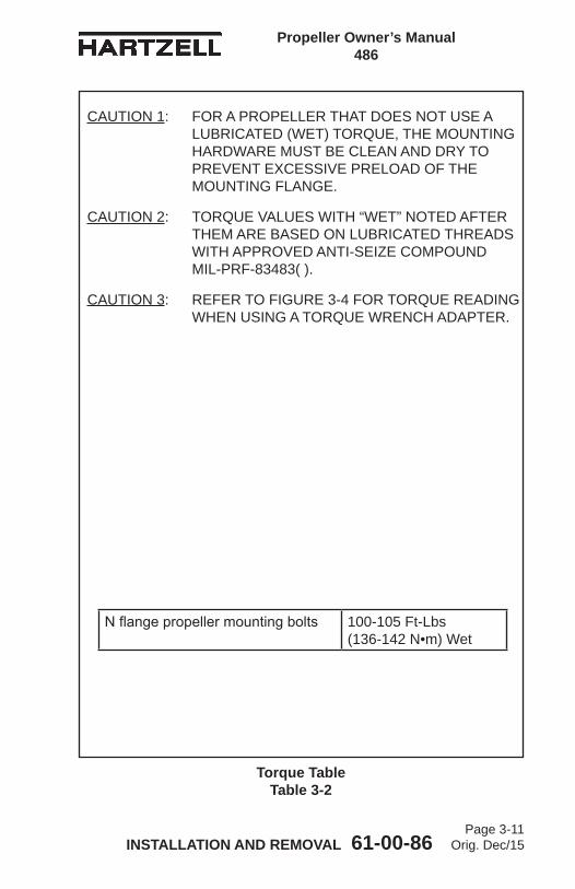
Propeller Owner’s Manual 486
INSTALLATION AND REMOVAL 61-00-86Page 3-11
Orig. Dec/15
Torque Table Table 3-2
CAUTION 1: FOR A PROPELLER THAT DOES NOT USE A LUBRICATED (WET) TORQUE, THE MOUNTING HARDWARE MUST BE CLEAN AND DRY TO PREVENT EXCESSIVE PRELOAD OF THE MOUNTING FLANGE.
CAUTION 2: TORQUE VALUES WITH “WET” NOTED AFTER THEM ARE BASED ON LUBRICATED THREADS WITH APPROVED ANTI-SEIZE COMPOUND MIL-PRF-83483( ).
CAUTION 3: REFER TO FIGURE 3-4 FOR TORQUE READING WHEN USING A TORQUE WRENCH ADAPTER.
Nflangepropellermountingbolts 100-105 Ft-Lbs (136-142 N•m) Wet
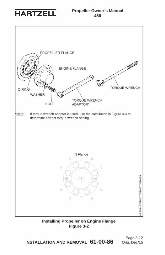
Propeller Owner’s Manual 486
INSTALLATION AND REMOVAL 61-00-86Page 3-12
Orig. Dec/15
AP
S05
43,W
1010
7,W
1012
7,W
1010
9
O-RING
PROPELLER FLANGE
ENGINE FLANGE
BOLTTORQUE WRENCH ADAPTOR*
TORQUE WRENCH
WASHER
*Note: If torque wrench adapter is used, use the calculation in Figure 3-4 to determine correct torque wrench setting.
Installing Propeller on Engine Flange Figure 3-2
N Flange

Propeller Owner’s Manual 486
INSTALLATION AND REMOVAL 61-00-86Page 3-13
Orig. Dec/15
Mounting Bolt and Washer Figure 3-3
AP
S02
79C
Chamfer of washer must face bolt head at installation. Washers without chamfer must be installed with rolled edges toward bolt head.
NOTE: Size of chamfer can vary from washer to washer.
Without chamfer
With chamfer

Propeller Owner’s Manual 486
INSTALLATION AND REMOVAL 61-00-86Page 3-14
Orig. Dec/15
Determining Torque Value When Using Torquing Adapter Figure 3-4
Torquing Adaptor
(actual torque required) X (torque wrench length) Torque wrench reading (torque wrench length) + (length of adapter) = to achieve required actual torque
100 Ft-Lb (136 N•m) x 1 ft (308.4 mm) 1 ft (308.4 mm) + 0.75 ft (228.6 mm)
= 57.1 Ft-Lb (77.4 N•m)
reading on torque wrench with 9-inch (228.6 mm) adapter for actual torque of 100 Ft-Lb (136 N•m)
<
EXAMPLE:
AP
S02
12A
Standard Torque Wrench
0.75 foot(228.6 mm)
1.00 foot(304.8 mm)
The correction shown is for an adapter that is aligned with the centerline of the torque wrench. If the adapter is angled 90 degrees relative to the torque wrench centerline, the torque wrench reading and actual torque applied will be equal.

Propeller Owner’s Manual 486
INSTALLATION AND REMOVAL 61-00-86Page 3-15
Orig. Dec/15
CAUTION: ID CHAMFER OF WASHER MUST BE FACING TOWARD THE BOLT HEAD. WASHERS WITHOUT CHAMFER MUST BE INSTALLED WITH ROLLED EDGES TOWARD THE BOLT HEAD. (REFER TO FIGURE 3-3).
(9) Install the mounting bolts with washers through the engineflangeandintothepropellerhubflange.RefertoFigure 3-2.
(10) Using a torque wrench and a torque wrench adapter Hartzell Propeller Inc. P/N AST-2877, torque all mounting bolts in sequences and steps shown in Figure 3-5. Refer to Table 3-2 and Figure 3-4 to determine the correct torque value.
(11) Safety all mounting bolts with 0.032 inch (0.81 mm) minimum diameter stainless steel wire or equivalent aircraft safety cable. (Two bolts per safety.)
(12) Decompress the external beta system and remove the beta system puller.
Diagram of Torquing Sequence for Propeller Mounting Bolts Figure 3-5
N Flange
SEQUENCE A SEQUENCE B Use Sequence A for steps one and two. Use Sequence B for step three.
Step 1 - Torque all bolts to 40 Ft-Lbs (54 N•m). Step 3 - Torque all bolts to Step 2 - Torque all bolts to 80 Ft-Lbs (108 N•m). Table 3-2.
TPI-4
86-0
04
15
3
8 4
7
62
18
7
6 3
2
45

Propeller Owner’s Manual 486
INSTALLATION AND REMOVAL 61-00-86Page 3-16
Orig. Dec/15
Beta Feedback Block Assembly and Beta Ring Clearance Figure 3-6
Beta Feedback Block Assembly Figure 3-7
Side clearance 0.001 inch (0.03 mm) minimum
upon installation.
Beta Feedback Block Assembly
Beta Ring
Snap Ring Yoke Unit
Cotter Pin
Clevis Pin Carbon Block Unit
AP
S01
68b
BP
S00
41
Snap Ring
Fillet A
Beta Linkage Lever

Propeller Owner’s Manual 486
INSTALLATION AND REMOVAL 61-00-86Page 3-17
Orig. Dec/15
CAUTION: THE BETA RING MUST NOT CONTACT ANY ENGINE COMPONENT OR MOUNTING BOLT SAFETY WIRE OR SAFETY CABLE. THE BETA MECHANISM FEEDBACK COULD BE DAMAGED IF IT CONTACTED ANY STATIC ENGINE COMPONENT WHILE ROTATING.
(13) Examine the beta ring to make sure that it is not in contact with any engine components or mounting bolt safety wire or safety cable.(a) If there is contact between the beta ring and any
engine components or mounting bolt safety wire orsafetycable,consultacertifiedpropellerrepairstation with the appropriate rating.
(14) Install the beta feedback block assembly into the beta linkage lever, in accordance with the airframe manufacturer’s instructions.(a) If the beta linkage lever and the snap ring are not
installed correctly, there could be interference between the beta linkage lever and Fillet A, as shown in Figure 3-6. Refer to Figure 3-6 and Figure 3-7.1 If there is interference at Fillet A, make a
chamfer in the beta linkage lever to clear Fillet A, as shown in Figure 3-6. The maximum radius in Fillet A as manufacturered is 0.015 inch (0.38 mm).
CAUTION: FIT THE BETA FEEDBACK BLOCK ASSEMBLY IN THE BETA RING WITH A MINIMUM SIDE CLEARANCE OF 0.001 INCH (0.03 mm). REFER TO FIGURE 3-6.
(15) Install the beta feedback block assembly into the beta ring. Refer to Figure 3-7.
(16) Install, adjust, and safety the beta linkage in accordance with the airframe manufacturer’s instructions.

Propeller Owner’s Manual 486
INSTALLATION AND REMOVAL 61-00-86Page 3-18
Orig. Dec/15
(17) If the propeller is equipped with an ice protection system that uses components supplied by Hartzell Propeller Inc., applicable instructions and technical information for the components supplied by Hartzell Propeller Inc. can be found in the following publications available on the Hartzell Propeller Inc. website at www.hartzellprop.com: (a) Manual 180 (30-61-80) - Propeller Ice Protection
System Manual(b) Manual 181 (30-60-81) - Propeller Ice Protection
Component Maintenance Manual(c) Manual 182 (61-12-82) - Propeller Electrical De-ice
Boot Removal and Installation Manual(d) Manual 183 (61-12-83) - Propeller Anti-icing Boot
Removal and Installation Manual(18) Propeller ice protection system components not
supplied by Hartzell Propeller Inc. are controlled by the applicable TC or STC holder’s Instructions for Continued Airworthiness (ICA).
(19) Install the propeller spinner dome in accordance with the section “Spinner Dome Installation” in this chapter.

Propeller Owner’s Manual 486
INSTALLATION AND REMOVAL 61-00-86Page 3-19
Orig. Dec/15
(This page is intentionally blank.)
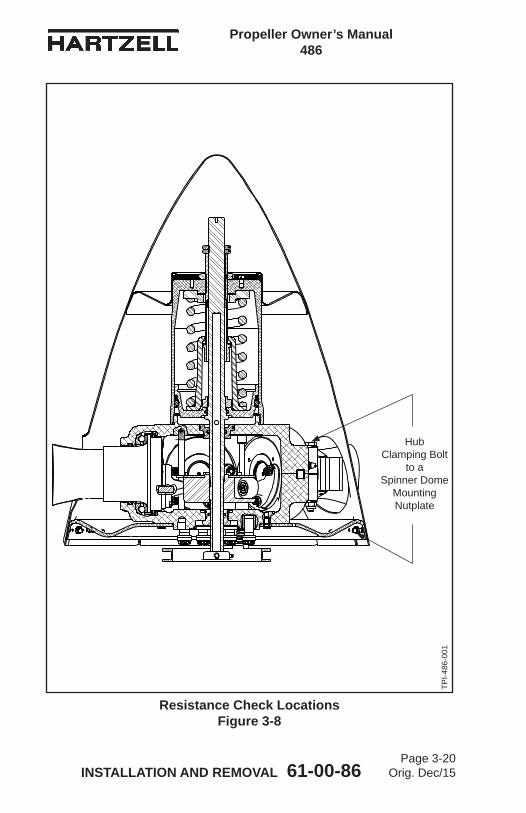
Propeller Owner’s Manual 486
INSTALLATION AND REMOVAL 61-00-86Page 3-20
Orig. Dec/15
Resistance Check Locations Figure 3-8
Hub Clamping Bolt
to a Spinner Dome
Mounting Nutplate
TPI-4
86-0
01

Propeller Owner’s Manual 486
INSTALLATION AND REMOVAL 61-00-86Page 3-21
Orig. Dec/15
4. Spinner Installation
CAUTION 1: TO PREVENT DAMAGE TO THE BLADE AND BLADE PAINT, WRAP THE BLADE SHANKS IN SEVERAL LAYERS OF MASKING OR DUCT TAPE BEFORE INSTALLING THE SPINNER DOME. REMOVE THE TAPE AFTER THE SPINNER IS INSTALLED.
CAUTION 2: SPINNER DOME WILL WOBBLE IF NOT ALIGNED PROPERLY. THIS MAY AFFECT DYNAMIC BALANCE OF PROPELLER.
NOTE: The following instructions relate to Hartzell Propeller Inc. spinners only. In some cases, the airframe manufacturer produced the spinner assembly. Refer to the airframe manufacturer’s manual for spinner installation instructions.
A. For a propeller model that uses a composite spinner, perform resistance checks as follows.(1) Using an ohm meter capable of accurately measuring
the required resistance in accordance with Table 3-3, measure the resistance from the hub clamping bolt to a spinner dome mounting nutplate on the bulkhead. Refer to Figure 3-8.
Resistance Checks Table 3-3
Area to Check Value
Hub Clamping Bolt to the Spinner Dome Mounting Nutplate 2 ohms Maximum
One Screw in Dome Mounting Hole to Another Screw in a Dome Mounting Hole 2 ohms Maximum

Propeller Owner’s Manual 486
INSTALLATION AND REMOVAL 61-00-86Page 3-22
Orig. Dec/15
Resistance Check of the Dome Figure 3-9
Dome Unit
B-3867-272 Screw
B-3860-10L Washer
B-3839-3 Nut (or any nut with 10-32 threads)
A-1040 Washer (or any non-conductive washer that prevents contact between the nut and the inside surface of the dome
2 ohms Maximum
Propeller Owner’s Manual 486
INSTALLATION AND REMOVAL 61-00-86Page 3-23
Orig. Dec/15
(2) Perform a resistance check of the dome unit before installation.NOTE: The dome is not installed on the bulkhead.(a) In each of two dome mounting holes with the
maximum distance possible between them, install a screw with washers and a nut in accordance with the information in Figure 3-9.
(b) Using an ohm meter capable of 20 Megohms, measure the resistance from one screw in a dome mounting hole to the other screw in a dome mounting hole. Refer to Figure 3-9 and Table 3-3 for limits. 1 If the resistance measurement is not satisfactory,
clean the contact points using a solvent such as Stoddard Kwik Dry solvent or equivalent and repeat the resistance measurement.
2 If the resistance measurement is not satisfactory for the two holes after cleaning, use two different holes with the maximum distance possible between them and repeat the measurement. Repeat the measurement using different holes with the maximum distance possible between them until the resistance measurement is satisfactory.
3 If after measuring between all possible combinations of holes the resistance measurement is not satisfactory, contact Hartzell Propeller Inc. for assistance.
(c) Remove the hardware from the dome mounting holes that was used for the resistance check of the dome.

Propeller Owner’s Manual 486
INSTALLATION AND REMOVAL 61-00-86Page 3-24
Orig. Dec/15
Spinner Assembly Figure 3-10
BP
S81
6
Forward Bulkhead Unit
SpinnerBulkhead Unit
Washer
Screw
SpinnerDome Spinner Mounting
Spacer
Spinner Bulkhead
Holes
Spinner Dome Mounting Holes
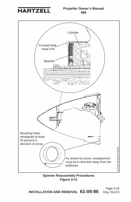
Propeller Owner’s Manual 486
INSTALLATION AND REMOVAL 61-00-86Page 3-25
Orig. Dec/15
Spinner Reassembly Procedures Figure 3-11
Mounting holes misaligned at least 25 percent in direction of arrow
As shown by arrow, misalignment must be in direction away from the bulkhead.
Spacers
Forward Bulk-head Unit
Cylinder
W10
150,
BP
S81
6,A
PS
6162
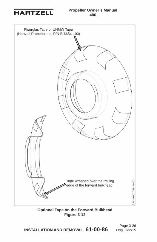
Propeller Owner’s Manual 486
INSTALLATION AND REMOVAL 61-00-86Page 3-26
Orig. Dec/15
Optional Tape on the Forward Bulkhead Figure 3-12
Flourglas Tape or UHMW Tape (Hartzell Propeller Inc. P/N B-6654-100)
Tape wrapped over the trailing edge of the forward bulkhead
TPI-1
4900
2,TP
I-149
003
Propeller Owner’s Manual 486
INSTALLATION AND REMOVAL 61-00-86Page 3-27
Orig. Dec/15
B. The spinner dome is supported by a forward bulkhead unit (see Figure 3-10) that encircles the propeller cylinder. (1) For propellers in this manual, if the forward bulkhead unit
doesnotfitsnuglyonthecylinder,thecylindermayneedtobewrappedwithoneormorelayersoffluoroglasorUHMW tape (Hartzell Propeller Inc. P/N B-6654-100). Apply a layer of tape, check, and repeat until the forward bulkheadunitfitssnuglyonthecylinder.NOTE 1: The forward bulkhead unit is positioned away
from the cylinder with spacers to cause the spinner dome mounting holes to stop short of full alignment with the bulkhead holes by 25% of the spinner dome mounting hole diameter. Refer to Figure 3-11.
NOTE 2: Positioning of the spinner dome mounting holes and forward bulkhead unit is accomplished by installing or removing spacers that are between the cylinder and forward bulkhead. Refer to Figure 3-11.
(a) Optionally, for a spinner dome that has a removable forwardbulkhead,applyalayeroffluoroglastapeorUHMW tape (Hartzell Propeller Inc. P/N B-6654-100) ontheoutboardflangeoftheforwardbulkheadtoprevent contact between the forward bulkhead and the spinner dome.1 Using acetone, denatured alcohol, or MEK,
clean the area where the tape will be applied.2 Cut eight pieces of tape that are approximately
three inches (76 mm) long.3 Apply the pieces of tape in equally spaced
locations on the forward bulkhead as shown in Figure 3-12.
4 Tape may be wrapped over trailing edge of the forward bulkhead as necessary.

Propeller Owner’s Manual 486
INSTALLATION AND REMOVAL 61-00-86Page 3-28
Orig. Dec/15
C. Carefully slide the spinner dome over the propeller and forward bulkhead to check for proper positioning of the spinner dome mounting holes. Add or remove spacers, if applicable, to obtain the spinner dome mounting hole and spinner bulkhead hole misalignment. Refer to Figure 3-11.
D. Pushthespinnerdomewithfirmpressuretowardthespinnerbulkhead unit to make sure that the spinner dome mounting holes will fully align with the spinner bulkhead holes. Remove a minimum quantity of spacers to obtain hole alignment while maintaining preload.
E. Attach the spinner dome to the spinner bulkhead or hoop unit with the supplied screws and washers.
5. Post-Installation ChecksA. Refer to the airframe manufacturer’s instructions for
post-installation checks.B. Perform a Maximum RPM (Static) Hydraulic Low Pitch
Stop Check as outlined in the Testing and Troubleshooting chapter of this manual.
Propeller Owner’s Manual 486
INSTALLATION AND REMOVAL 61-00-86Page 3-29
Orig. Dec/15
6. Spinner Removal
CAUTION: TO PREVENT DAMAGING THE BLADE AND BLADE PAINT, WRAP THE BLADE SHANKS IN SEVERAL LAYERS OF MASKING OR DUCT TAPE BEFORE REMOVING THE SPINNER DOME.
A. Remove the screws and washers that secure the spinner dome to the spinner bulkhead.
B. Remove the spinner dome.
7. Propeller RemovalA. Removal of ( )D3-( )( )( ) Propellers
WARNING: FOR SAFETY REASONS, PUT THE PROPELLER IN THE FEATHER POSITION BEFORE IT IS REMOVED FROM THE AIRCRAFT.
CAUTION: INSTRUCTIONS AND PROCEDURES IN THIS SECTION MAY INVOLVE PROPELLER CRITICAL PARTS. REFER TO THE INTRODUCTION CHAPTER OF THIS MANUAL FOR INFORMATION ABOUT PROPELLER CRITICAL PARTS. REFER TO THE ILLUSTRATED PARTS LIST CHAPTER OF THE APPLICABLE OVERHAUL MANUAL(S) FOR THE IDENTIFICATION OF SPECIFIC PROPELLER CRITICAL PARTS.
(1) Remove the spinner dome in accordance with the section “Spinner Dome Removal” in this chapter.
Propeller Owner’s Manual 486
INSTALLATION AND REMOVAL 61-00-86Page 3-30
Orig. Dec/15
(2) If the propeller is equipped with an ice protection system that uses components supplied by Hartzell Propeller Inc., applicable instructions and technical information for the components supplied by Hartzell Propeller Inc. can be found in the following publications available on the Hartzell Propeller Inc. website at www.hartzellprop.com: (a) Manual 180 (30-61-80) - Propeller Ice Protection
System Manual(b) Manual 181 (30-60-81) - Propeller Ice Protection
Component Maintenance Manual(c) Manual 182 (61-12-82) - Propeller Electrical De-ice
Boot Removal and Installation Manual(d) Manual 183 (61-12-83) - Propeller Anti-icing Boot
Removal and Installation Manual(3) Propeller ice protection system components not
supplied by Hartzell Propeller Inc. are controlled by the applicable TC or STC holder’s Instructions for Continued Airworthiness (ICA).
(4) Disconnect the engine beta linkage and beta feedback block assembly from the beta ring in accordance with the airframe manufacturer’s instructions.(a) Remove the snap ring that retains the beta feedback
block assembly to the beta linkage. Refer to Figure 3-7.
(b) Remove the beta feedback block assembly. Refer to Figure 3-6.
(5) Use the beta system puller CST-2987 to compress the beta system spring and pull the beta ring toward the propeller to expose the propeller mounting bolts and washers. Refer to Figure 3-1.
Propeller Owner’s Manual 486
INSTALLATION AND REMOVAL 61-00-86Page 3-31
Orig. Dec/15
WARNING 1: DURING ENGINE INSTALLATION OR REMOVAL, USING THE PROPELLER TO SUPPORT THE WEIGHT OF THE ENGINE IS NOT AUTHORIZED. UNAPPROVED INSTALLATION AND REMOVAL TECHNIQUES MAY CAUSE DAMAGE TO THE PROPELLER THAT MAY LEAD TO FAILURE AND RESULT IN AN AIRCRAFT ACCIDENT.
WARNING 2: DURING PROPELLER REMOVAL, AIRFRAME MANUFACTURER’S MANUALS AND PROCEDURES MUST BE FOLLOWED BECAUSE THEY MAY CONTAIN ISSUES VITAL TO AIRCRAFT SAFETY THAT ARE NOT CONTAINED IN THIS MANUAL OR THE HARTZELL PROPELLER INC. OVERHAUL MANUAL 496 (61-10-96).
WARNING 3: MAKE SURE THE SLING IS RATED UP TO 800 LBS (363 KG) TO SUPPORT THE WEIGHT OF THE PROPELLER ASSEMBLY DURING REMOVAL.
(6) Cut and remove the safety wire or safety cable on the propeller mounting bolts.
(7) Support the propeller assembly with a sling.(a) Supporting the propeller with a sling may be delayed
until all but two mounting bolts and washers have been removed to permit rotating the propeller for ease of bolt removal.
(b) If the propeller will be reinstalled and it has been dynamically balanced, make an identifying mark on the propeller hub and a matching mark on theengineflangetomakesureofproperorientationduring re-installation to prevent dynamic imbalance.

Propeller Owner’s Manual 486
INSTALLATION AND REMOVAL 61-00-86Page 3-32
Orig. Dec/15
CAUTION: DISCARD THE PROPELLER MOUNTING BOLTS IF THEY ARE DAMAGED OR CORRODED, OR WHEN THE PROPELLER IS REMOVED FOR OVERHAUL.
(8) Remove the propeller mounting bolts and washers.(a) If the propeller is removed between overhaul
intervals, mounting bolts and washers may be reused if they are not damaged or corroded.
CAUTION: USE ADEQUATE PRECAUTIONS TO PROTECT THE PROPELLER ASSEMBLY FROM DAMAGE WHEN IT IS REMOVED FROM THE AIRCRAFT ENGINE AND WHEN IT IS STORED.
(9) Using the support sling, lift the propeller from the mountingflange.
(10) Remove and discard propeller mounting O-ring.(11) Install suitable covers on the pitch change rod opening,
propellermountingflange,andengineflangetopreventtheintroduction of contamination.
(12) Decompress and remove beta system puller.(13) Put the propeller on a suitable cart for transportation.

Propeller Owner’s Manual 486
TESTING AND TROUBLESHOOTING 61-00-86Page 4-1
Orig. Dec/15
TESTING AND TROUBLESHOOTING - CONTENTS
1. Operational Tests .................................................................... 4-3A. Initial Run-Up ..................................................................... 4-3B. Post-Run Check ................................................................. 4-3C. Maximum RPM (Static) Hydraulic Low Pitch Stop Check .. 4-4D. Reverse Pitch Stop Adjustment ......................................... 4-4E. Feathering Pitch Stop Adjustment ...................................... 4-4F. Propeller Ice Protection System ......................................... 4-4
2. Troubleshooting ...................................................................... 4-6A. Hunting and Surging .......................................................... 4-6B. Engine Speed Varies with Airspeed ................................... 4-7C. Loss of Propeller Control ................................................... 4-7D. Failure to Feather (or feathers slowly) ............................... 4-8E. Failure to Unfeather ........................................................... 4-8F. Vibration ............................................................................. 4-9G. Propeller Overspeed ........................................................ 4-10H. Propeller Underspeed ...................................................... 4-10I. Oil or Grease Leakage ..................................................... 4-11

Propeller Owner’s Manual 486
TESTING AND TROUBLESHOOTING 61-00-86Page 4-2
Orig. Dec/15
(This page is intentionally blank.)
Propeller Owner’s Manual 486
TESTING AND TROUBLESHOOTING 61-00-86Page 4-3
Orig. Dec/15
1. Operational TestsFollowing propeller installation, and before flight, the propeller hydraulic system must be purged of air and proper operation verified.
WARNING: REFER TO THE AIRCRAFT MAINTENANCE MANUAL FOR ADDITIONAL PROCEDURES THAT MAY BE REQUIRED AFTER PROPELLER INSTALLATION.
CAUTION: INSTRUCTIONS AND PROCEDURES IN THIS SECTION MAY INVOLVE PROPELLER CRITICAL PARTS. REFER TO THE INTRODUCTION CHAPTER OF THIS MANUAL FOR INFORMATION ABOUT PROPELLER CRITICAL PARTS. REFER TO THE ILLUSTRATED PARTS LIST CHAPTER OF THE APPLICABLE OVERHAUL MANUAL(S) FOR THE IDENTIFICATION OF SPECIFIC PROPELLER CRITICAL PARTS.
A. Initial Run-Up(1) Perform engine start and warm-up in accordance with
the Pilot's Operating Handbook (POH).NOTE: Air trapped in the propeller hydraulic cylinder
will cause pitch control to be imprecise and may result in propeller surging.
(2) Cycle the propeller control throughout its operating blade angle range from reverse or low, to high (or as directed by the POH).
(3) Repeat this procedure at least three times to purge air from the propeller hydraulic system and to introduce warmed oil to the cylinder.
(4) Verify proper operation from low pitch to high pitch and throughout operating range.
(5) Shut down engine in accordance with the POH.B. Post-Run Check
(1) After engine shutdown, examine the propeller for signs of engine oil leakage.
Propeller Owner’s Manual 486
TESTING AND TROUBLESHOOTING 61-00-86Page 4-4
Orig. Dec/15
C. Maximum RPM (Static) Hydraulic Low Pitch Stop Check(1) The Maximum RPM (hydraulic low pitch stop) is
normally set at the factory per the aircraft manufacturer's requirements, and should not require any additional adjustment. Adjustments may be required after maintenance or because of specific aircraft variances.
(2) Adjustments must be done in accordance with the airframe manufacturer's specification found in the airframe manufacturer's manual.
D. Reverse Pitch Stop Adjustment(1) The reverse pitch stop adjustment is set at the factory
per the aircraft manufacturer's recommendations. This stop is adjustable only by a certified propeller repair station with the appropriate rating, the aircraft manufacturer, or Hartzell Propeller Inc.
E. Feathering Pitch Stop Adjustment(1) The feathering pitch stop is set at the factory per the
aircraft manufacturer's recommendations. This stop is adjustable only by a certified propeller repair station with the appropriate rating, the aircraft manufacturer, or Hartzell Propeller Inc.
F. Propeller Ice Protection System(1) Electric De-ice System
(a) Consult the Pilot Operating Handbook (POH) (including all supplements) regarding flight into conditions of known icing. The aircraft may not be certificated for flight in known icing conditions, even though propeller de-ice equipment is installed.
(b) Refer to the Anti-ice and De-ice Systems chapter of this manual for functional tests of the ice protection system.

Propeller Owner’s Manual 486
TESTING AND TROUBLESHOOTING 61-00-86Page 4-5
Orig. Dec/15
(2) Anti-ice System(a) Consult the Pilot Operating Handbook (including
all supplements) regarding flight into conditions of known icing. The aircraft may not be certificated for flight in known icing conditions, even though propeller anti-ice equipment is installed.
(b) Refer to the Anti-ice and De-ice Systems chapter of this manual for functional tests of the anti-ice system.

Propeller Owner’s Manual 486
TESTING AND TROUBLESHOOTING 61-00-86Page 4-6
Orig. Dec/15
2. Troubleshooting
CAUTION: INSTRUCTIONS AND PROCEDURES IN THIS SECTION MAY INVOLVE PROPELLER CRITICAL PARTS. REFER TO THE INTRODUCTION CHAPTER OF THIS MANUAL FOR INFORMATION ABOUT PROPELLER CRITICAL PARTS. REFER TO THE ILLUSTRATED PARTS LIST CHAPTER OF THE APPLICABLE OVERHAUL MANUAL(S) FOR THE IDENTIFICATION OF SPECIFIC PROPELLER CRITICAL PARTS.
A. Hunting and SurgingHunting is characterized by a cyclic variation in engine speed above and below desired speed. Surging is characterized by a large increase/decrease in engine speed, followed by a return to set speed after one or two occurrences. (1) If propeller is hunting, a certified propeller repair station
with the appropriate rating should check:(a) Governor(b) Fuel control(c) Synchrophaser, or synchronizer.
(2) If propeller is surging:(a) Perform the steps 1.A.(1) through 1.A.(5) under
Operational Tests section in this chapter to release trapped air from the propeller. 1 If surging reoccurs it is most likely due to a faulty
governor. a Have the governor tested a certified
propeller repair station with the appropriate rating.
(b) Hunting and/or surging may also be caused by friction or binding within the governor control, or internal propeller corrosion, which causes the propeller to react slower to governor commands. 1 To isolate these faults, the propeller must be
tested on a test bench at a certified propeller repair station with the appropriate rating.

Propeller Owner’s Manual 486
TESTING AND TROUBLESHOOTING 61-00-86Page 4-7
Orig. Dec/15
B. Engine Speed Varies with Airspeed(1) Constant speed propeller models will experience some
small variances in engine speed that are normal and are no cause for concern.
(2) Increase in engine speed while descending or increasing airspeed:(a) Governor is not reducing oil volume in the propeller.(b) Friction in propeller.
(3) Decrease in engine speed while increasing airspeed:(a) Governor pilot valve is stuck and is excessively
decreasing oil volume.(b) Feathering command engaged on propeller pitch
control.(4) Increase in engine speed while decreasing airspeed:
(a) Governor pilot valve is stuck and is excessively increasing oil volume.
(5) Decrease in engine speed while decreasing airspeed:(a) Governor is not increasing oil volume in the propeller.(b) Engine oil transfer system leaking excessively.(c) Friction in propeller.
C. Loss of Propeller Control(1) Propeller goes to uncommanded high pitch (or feather).
(a) Loss of propeller oil pressure - check:1 Governor pressure relief valve.2 Governor drive.3 Engine oil supply.
(2) Propeller goes to uncommanded low pitch (High RPM).(a) Governor pilot valve sticking.
(3) RPM increases with power and airspeed, propeller RPM control has little or no effect.(a) Excessive friction in blade bearings or pitch changing
mechanism.(b) Broken feathering spring.
(4) RPM control sluggish (especially on reducing RPM)(a) Broken feathering spring.

Propeller Owner’s Manual 486
TESTING AND TROUBLESHOOTING 61-00-86Page 4-8
Orig. Dec/15
D. Failure to Feather (or feathers slowly)(1) Broken feathering spring.(2) Check for proper function and rigging of propeller/governor
control linkage.(3) Check governor drain function.(4) Propeller must be checked for misadjustment or internal
corrosion (usually in blade bearings or pitch changing mechanism) that results in excessive friction. This must be accomplished at a certified propeller repair station with the appropriate rating.
E. Failure to Unfeather(1) Check for proper function and rigging of propeller control
linkage.(2) Check governor function.(3) Propeller must be checked for misadjustment or internal
corrosion (usually in blade bearings or pitch change mechanism) that results in excessive friction. This must be accomplished at certified propeller repair station with the appropriate rating.

Propeller Owner’s Manual 486
TESTING AND TROUBLESHOOTING 61-00-86Page 4-9
Orig. Dec/15
F. Vibration
CAUTION 1: ANY VIBRATION THAT CAN BE DESCRIBED AS APPEARING SUDDENLY, OR IS ACCOMPANIED BY UNEXPLAINED GREASE LEAKAGE, SHOULD BE INVESTIGATED IMMEDIATELY BEFORE FURTHER FLIGHT.
CAUTION 2: VIBRATION PROBLEMS BECAUSE OF PROPELLER SYSTEM IMBALANCE ARE NORMALLY FELT THROUGHOUT THE RPM RANGE, WITH THE INTENSITY OF VIBRATION INCREASING WITH RPM. VIBRATION PROBLEMS THAT OCCUR IN A NARROW RPM RANGE ARE A SYMPTOM OF RESONANCE THAT IS POTENTIALLY HARMFUL TO THE PROPELLER. AVOID OPERATION UNTIL THE PROPELLER CAN BE CHECKED BY A CERTIFIED PROPELLER REPAIR STATION WITH THE APPROPRIATE RATING.
(1) Check:(a) Control surfaces, exhaust system, landing gear
doors, etc. for excessive play, which may be causing vibration unrelated to the propeller.
(b) Uneven lubrication of propeller.(c) Proper engine/propeller flange mating. (d) Blade track. Refer to the Inspection and Check
chapter of this manual for procedure.(e) Blade angles: Blade angle must be within tolerance
between blades and on the propeller as a whole. For the blade angle check procedure, refer to Propeller Overhaul Manual 496 (61-10-96).
(f) Spinner for cracks, improper installation, or "wobble" during operation.
(g) Static balance.
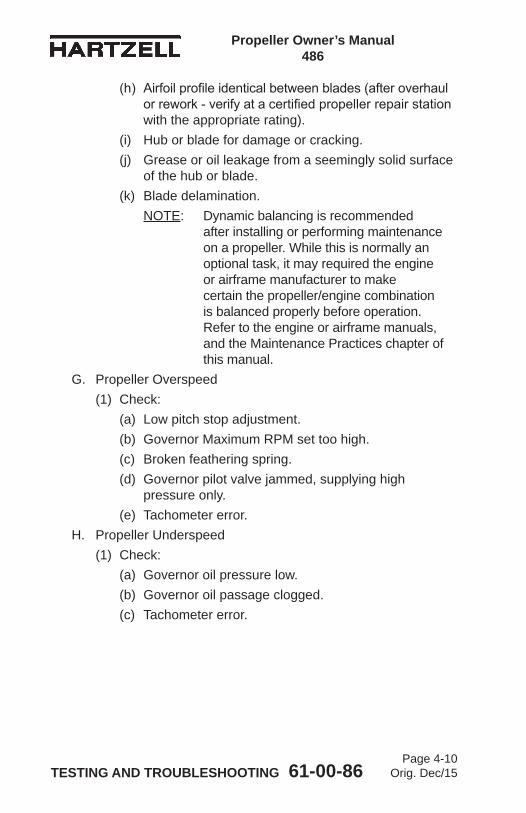
Propeller Owner’s Manual 486
TESTING AND TROUBLESHOOTING 61-00-86Page 4-10
Orig. Dec/15
(h) Airfoil profile identical between blades (after overhaul or rework - verify at a certified propeller repair station with the appropriate rating).
(i) Hub or blade for damage or cracking.(j) Grease or oil leakage from a seemingly solid surface
of the hub or blade.(k) Blade delamination.
NOTE: Dynamic balancing is recommended after installing or performing maintenance on a propeller. While this is normally an optional task, it may required the engine or airframe manufacturer to make certain the propeller/engine combination is balanced properly before operation. Refer to the engine or airframe manuals, and the Maintenance Practices chapter of this manual.
G. Propeller Overspeed(1) Check:
(a) Low pitch stop adjustment.(b) Governor Maximum RPM set too high.(c) Broken feathering spring.(d) Governor pilot valve jammed, supplying high
pressure only.(e) Tachometer error.
H. Propeller Underspeed(1) Check:
(a) Governor oil pressure low.(b) Governor oil passage clogged.(c) Tachometer error.

Propeller Owner’s Manual 486
TESTING AND TROUBLESHOOTING 61-00-86Page 4-11
Orig. Dec/15
I. Oil or Grease LeakageNOTE: A new propeller may leak slightly during the first
several hours of operation. This leakage may be caused by the seating of seals and O-rings, and the slinging of lubricants used during assembly. Such leakage should cease within the first ten hours of operation.
CAUTION: GREASE LEAKAGE THAT CAN BE DESCRIBED AS EXCESSIVE AND APPEARING SUDDENLY, ESPECIALLY WHEN ACCOMPANIED BY VIBRATION, SHOULD BE INVESTIGATED IMMEDIATELY BEFORE FURTHER FLIGHT.
(1) Grease Leakage - Probable Cause:(a) Improperly torqued or loose lubrication fitting(b) Defective lubrication fitting(c) Faulty seal at the blade socket between the blade
and hub1 Refer to a certified propeller repair station with
the appropriate rating for replacement of the seal.
(d) Leakage from the hub and beta rod interface1 Over greased hub
a Refer to a certified propeller repair station with the appropriate rating for removal of excess grease.
2 Faulty seala Refer to a certified propeller repair station
with the appropriate rating for replacement of the seal.
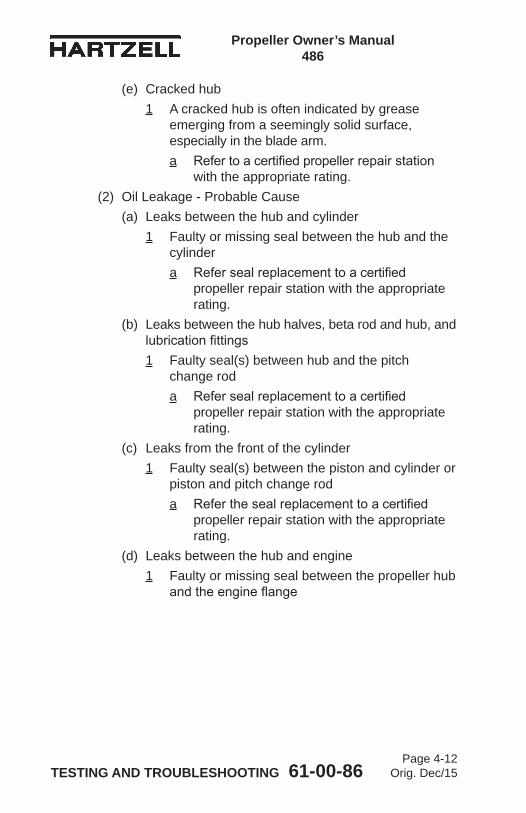
Propeller Owner’s Manual 486
TESTING AND TROUBLESHOOTING 61-00-86Page 4-12
Orig. Dec/15
(e) Cracked hub1 A cracked hub is often indicated by grease
emerging from a seemingly solid surface, especially in the blade arm. a Refer to a certified propeller repair station
with the appropriate rating.(2) Oil Leakage - Probable Cause
(a) Leaks between the hub and cylinder1 Faulty or missing seal between the hub and the
cylindera Refer seal replacement to a certified
propeller repair station with the appropriate rating.
(b) Leaks between the hub halves, beta rod and hub, and lubrication fittings1 Faulty seal(s) between hub and the pitch
change roda Refer seal replacement to a certified
propeller repair station with the appropriate rating.
(c) Leaks from the front of the cylinder1 Faulty seal(s) between the piston and cylinder or
piston and pitch change roda Refer the seal replacement to a certified
propeller repair station with the appropriate rating.
(d) Leaks between the hub and engine1 Faulty or missing seal between the propeller hub
and the engine flange
Propeller Owner’s Manual 486
INSPECTION AND CHECK 61-00-86Page 5-1
Orig. Dec/15
INSPECTION AND CHECK - CONTENTS
1. Pre-Flight Checks ................................................................... 5-3
2. Operational Checks ................................................................ 5-5
3. Required Periodic Inspections and Maintenance ................... 5-7A. Periodic Inspections .......................................................... 5-7B. Periodic Maintenance ........................................................ 5-9C. Airworthiness Limitations ................................................... 5-9D. Overhaul Periods ............................................................. 5-10
4. Inspection Procedures .......................................................... 5-11A. Blade Damage ................................................................. 5-11B. Grease or Oil Leakage ..................................................... 5-11C. Vibration ........................................................................... 5-13D. Tachometer Inspection ..................................................... 5-15E. Blade Track ...................................................................... 5-17F. Loose Blades .................................................................. 5-19G. Corrosion ......................................................................... 5-20H. Spinner Damage ............................................................. 5-20I. Electric De-ice System ..................................................... 5-20J. Anti-ice System ................................................................ 5-20
5. Special Inspections ............................................................... 5-23A. Overspeed/Overtorque .................................................... 5-23B. Propeller Ground Idle Operating Restrictions .................. 5-25C. Lightning Strike ................................................................ 5-31D. Foreign Object Strike ....................................................... 5-34E. Fire Damage or Heat Damage ......................................... 5-36
6. Long Term Storage ............................................................... 5-36

Propeller Owner’s Manual 486
INSPECTION AND CHECK 61-00-86Page 5-2
Orig. Dec/15
LIST OF FIGURES
Checking Blade Track....................................Figure 5-1 ........... 5-16
Blade Play .....................................................Figure 5-2 ........... 5-16
Turbine Engine Overspeed Limits .................Figure 5-3 ........... 5-21
Turbine Engine Overtorque Limits .................Figure 5-4 ........... 5-22
Example of an Evaluation of Ground Idle RPM Check ........................Figure 5-5 ........... 5-26
Corrective Action Required ............................Figure 5-6 ........... 5-27
Evidence of Lightning Strike Damage to Composite Blade ....................................Figure 5-7 ........... 5-32
Propeller Owner’s Manual 486
INSPECTION AND CHECK 61-00-86Page 5-3
Orig. Dec/15
1. Pre-Flight ChecksFollow propeller preflight inspection procedures as specified in the Pilot Operating Handbook (POH) or this manual. In addition, perform the following inspections:
CAUTION: INSTRUCTIONS AND PROCEDURES IN THIS SECTION MAY INVOLVE PROPELLER CRITICAL PARTS. REFER TO THE INTRODUCTION CHAPTER OF THIS MANUAL FOR INFORMATION ABOUT PROPELLER CRITICAL PARTS. REFER TO THE ILLUSTRATED PARTS LIST CHAPTER OF THE APPLICABLE OVERHAUL MANUAL(S) FOR THE IDENTIFICATION OF SPECIFIC PROPELLER CRITICAL PARTS.
A. Blades(1) Visually inspect the entire blade and the erosion shield for
nicks, gouges, looseness of material, erosion, cracks, and debonds. Refer to the Maintenance Practices chapter of this manual for composite blade airworthy damage limits.
(2) Visually inspect the blades for lightning strike. Refer to the Lightning Strike section in this chapter for a description of damage.
(3) Defects or damage discovered during preflight inspection must be evaluated in accordance with allowables outlined in the Maintenance Practices chapter of this manual to determine if repairs are required before further flight.
B. Inspect the spinner and visible blade retention components for damage or cracks. Repair or replace components, as required, before further flight.
C. Check for loose/missing hardware. Retighten or reinstall as necessary.
Propeller Owner’s Manual 486
INSPECTION AND CHECK 61-00-86Page 5-4
Orig. Dec/15
WARNING: ABNORMAL GREASE LEAKAGE CAN BE AN INDICATION OF A FAILING PROPELLER BLADE OR BLADE RETENTION COMPONENT. AN IN-FLIGHT BLADE SEPARATION CAN RESULT IN A CATASTROPHIC AIRCRAFT ACCIDENT.
D. Inspect for grease and oil leakage and determine the source.E. Check the blades for radial play or movement of the blade tip
(in and out or back and forth). Refer to Loose Blades in the Inspection Procedures section of this chapter for blade play limits.
F. Inspect de-ice boots (if installed) for damage. Refer to the Anti-ice and De-ice Systems chapter of this manual for inspection information.
G. Examine the propeller speed control and operation from reverse or low pitch to high pitch, using the procedure specified in the Pilot Operating Handbook (POH) for the aircraft.
WARNING: ABNORMAL VIBRATION CAN BE AN INDICATION OF A FAILING PROPELLER BLADE OR BLADE RETENTION COMPONENT. AN IN-FLIGHT BLADE SEPARATION CAN RESULT IN A CATASTROPHIC AIRCRAFT ACCIDENT.
H. Perform initial run-up as outlined in the Operational Tests section of in the Testing and Troubleshooting chapter in this manual.
I. Check for any abnormal vibration during this run-up. If vibration occurs, shut the engine down, determine the cause, and correct it before further flight. Refer to the Vibration section in the Testing and Troubleshooting chapter of this manual.
J. Refer to the Periodic Inspections section of this chapter for additional inspection information and possible corrections to any discrepancies discovered as a result of pre-flight checks.

Propeller Owner’s Manual 486
INSPECTION AND CHECK 61-00-86Page 5-5
Orig. Dec/15
2. Operational Checks
CAUTION: INSTRUCTIONS AND PROCEDURES IN THIS SECTION MAY INVOLVE PROPELLER CRITICAL PARTS. REFER TO THE INTRODUCTION CHAPTER OF THIS MANUAL FOR INFORMATION ABOUT PROPELLER CRITICAL PARTS. REFER TO THE ILLUSTRATED PARTS LIST CHAPTER OF THE APPLICABLE OVERHAUL MANUAL(S) FOR THE IDENTIFICATION OF SPECIFIC PROPELLER CRITICAL PARTS.
A. Following propeller installation or as required, perform initial run-up as outlined in Operational Tests in the Testing and Troubleshooting chapter of this manual.
B. Check the propeller speed control and operation from reverse or low pitch to high pitch, using the procedure specified in the Pilot Operating Handbook (POH) for the aircraft.
C. Check for any abnormal vibration during this run-up. If vibration occurs, shut the engine down, determine the cause, and correct it before further flight. Refer to the Vibration section in the Testing and Troubleshooting chapter of this manual.
D. Refer to Periodic Inspections in this chapter for additional inspection information and possible corrections to any discrepancies discovered as a result of Pre-Flight Checks.
E. Refer to the POH and/or AMM for aircraft manufacturers recommendations.
Propeller Owner’s Manual 486
INSPECTION AND CHECK 61-00-86Page 5-6
Orig. Dec/15
(This page is intentionally blank.)

Propeller Owner’s Manual 486
INSPECTION AND CHECK 61-00-86Page 5-7
Orig. Dec/15
3. Required Periodic Inspections and Maintenance
CAUTION: INSTRUCTIONS AND PROCEDURES IN THIS SECTION MAY INVOLVE PROPELLER CRITICAL PARTS. REFER TO THE INTRODUCTION CHAPTER OF THIS MANUAL FOR INFORMATION ABOUT PROPELLER CRITICAL PARTS. REFER TO THE ILLUSTRATED PARTS LIST CHAPTER OF THE APPLICABLE OVERHAUL MANUAL(S) FOR THE IDENTIFICATION OF SPECIFIC PROPELLER CRITICAL PARTS.
A. Periodic Inspections (1) Except for the blade and erosion shield coin-tap
inspection in this section, accomplish a detailed inspection at 400 hour intervals not to exceed twelve (12) calendar months. Procedures involved in these inspections are detailed below.(a) Inspection and maintenance specified by an airframe
manufacturer’s maintenance program and approved by the applicable airworthiness agency may not coincide with the inspection time intervals specified. In this situation, the airframe manufacturer’s schedule may be applied with the exception that the calendar limit for the inspection interval may not exceed twelve (12) months.
(b) Refer to Inspection Procedures in this chapter for additional inspection information and possible corrections to any discrepancies discovered as a result of the Periodic Inspection.
(2) Remove the spinner dome.

Propeller Owner’s Manual 486
INSPECTION AND CHECK 61-00-86Page 5-8
Orig. Dec/15
CAUTION: DO NOT ATTEMPT TO REPAIR A CRACKED BLADE.
(3) Visually examine the blade and the erosion shield for nicks, gouges, looseness of material, erosion, cracks and debonds. (a) Refer to the Composite Blade Repairs section in the
Maintenance Practices chapter of this manual for additional information.
(b) A cracked blade must be referred to a certified propeller repair station with the appropriate rating.
CAUTION: DO NOT ATTEMPT TO REPAIR A CRACKED HUB.
(4) Visually inspect the hub parts for cracks or wear. (a) Refer to Grease and Oil Leaks in the Inspection
Procedures section of this chapter for procedure. (b) A cracked hub must be referred to a certified
propeller repair station with the appropriate rating. (5) Check for oil and grease leaks. Refer to Grease and
Oil Leaks in the Inspection Procedures section of this chapter.
(6) If a blade track problem is suspected, check the blade track. Refer to Blade Track in the Inspection Procedures section of this chapter.
(7) Blade and Erosion Shield Coin-tap(a) Perform a coin-tap test of the exposed section of
each blade, not to exceed 1200 hours, and the exposed section of the erosion shield surface, not to exceed 600 hours.1 The coin-tap test will indicate a delamination or
debond by an apparent audible change.2 For the coin-tap test procedure, refer to the
Coin-tap Test section in the Maintenance Practices chapter of this manual.
Propeller Owner’s Manual 486
INSPECTION AND CHECK 61-00-86Page 5-9
Orig. Dec/15
B. Periodic Maintenance(1) Lubricate the propeller assembly. Refer to the
Lubrication section in the Maintenance Practices chapter of this manual for intervals and procedures.
C. Airworthiness Limitations(1) Certain components, as well as the entire propeller
may have specific life limits established as part of the certification by the FAA. Such limits require mandatory replacement of specified parts after a defined number of hours and/or cycles of use.
(2) Life limited component times may exist for the propeller models included in this manual. Refer to the Airworthiness Limitations chapter of this manual.
(3) Operators are urged to keep informed of airworthiness information via Hartzell Propeller Inc. Service Bulletins and Service Letters, which are available from Hartzell Propeller Inc distributors or from Hartzell Propeller Inc. by subscription. Selected information is also available on the Hartzell Propeller Inc. website at www.hartzellprop.com.

Propeller Owner’s Manual 486
INSPECTION AND CHECK 61-00-86Page 5-10
Orig. Dec/15
D. Overhaul Periods(1) General
(a) In flight, the propeller is constantly subjected to vibration from the engine and the airstream, as well as high centrifugal forces.
(b) The propeller is also subject to corrosion and general deterioration due to aging. Under these conditions, metal fatigue or mechanical failures can occur.
(c) To protect your safety and your investment, and to maximize the safe operating lifetime of your propeller, it is essential that a propeller be properly maintained and overhauled according to the recommended service procedures.
CAUTION 1: OVERHAUL PERIODS LISTED BELOW, ALTHOUGH CURRENT AT THE TIME OF PUBLICATION, ARE FOR REFERENCE PURPOSES ONLY. OVERHAUL PERIODS MAY BE INCREASED OR DECREASED AS A RESULT OF EVALUATION.
CAUTION 2: CHECK THE LATEST REVISION OF HARTZELL PROPELLER INC. SERVICE LETTER HC-SL-61-61Y FOR THE MOST CURRENT INFORMATION.
(2) Propellers must be overhauled at 4000 hours or 72 months, whichever occurs first.
Propeller Owner’s Manual 486
INSPECTION AND CHECK 61-00-86Page 5-11
Orig. Dec/15
4. Inspection Procedures
CAUTION: INSTRUCTIONS AND PROCEDURES IN THIS SECTION MAY INVOLVE PROPELLER CRITICAL PARTS. REFER TO THE INTRODUCTION CHAPTER OF THIS MANUAL FOR INFORMATION ABOUT PROPELLER CRITICAL PARTS. REFER TO THE ILLUSTRATED PARTS LIST CHAPTER OF THE APPLICABLE OVERHAUL MANUAL(S) FOR THE IDENTIFICATION OF SPECIFIC PROPELLER CRITICAL PARTS.
The following inspections must be made on a regular basis, either before flight, during required periodic inspection, as described in this chapter, or if a problem is noted. Possible corrections to problems discovered during inspections, additional inspections, and limits are detailed in the following inspection procedures.A. Blade Damage
(1) Refer to the Composite Blade Repairs section in the Maintenance Practices chapter of this manual for information regarding blade damage.
B. Grease or Oil Leakage
WARNING: UNUSUAL OR ABNORMAL GREASE LEAKAGE OR VIBRATION, WHERE THE CONDITION STARTED SUDDENLY, CAN BE AN INDICATION OF A FAILING PROPELLER BLADE OR BLADE RETENTION COMPONENT. AN INFLIGHT BLADE SEPARATION CAN RESULT IN DEATH, SERIOUS BODILY INJURY, AND/OR SUBSTANTIAL PROPERTY DAMAGE. UNUSUAL OR ABNORMAL GREASE LEAKAGE OR VIBRATION DEMANDS IMMEDIATE INSPECTION FOR A POSSIBLE CRACKED HUB.
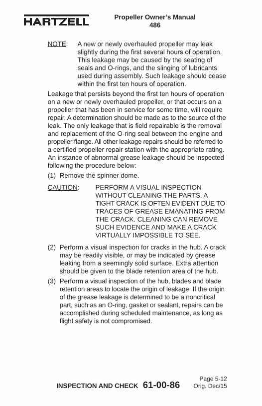
Propeller Owner’s Manual 486
INSPECTION AND CHECK 61-00-86Page 5-12
Orig. Dec/15
NOTE: A new or newly overhauled propeller may leak slightly during the first several hours of operation. This leakage may be caused by the seating of seals and O-rings, and the slinging of lubricants used during assembly. Such leakage should cease within the first ten hours of operation.
Leakage that persists beyond the first ten hours of operation on a new or newly overhauled propeller, or that occurs on a propeller that has been in service for some time, will require repair. A determination should be made as to the source of the leak. The only leakage that is field repairable is the removal and replacement of the O-ring seal between the engine and propeller flange. All other leakage repairs should be referred to a certified propeller repair station with the appropriate rating. An instance of abnormal grease leakage should be inspected following the procedure below:(1) Remove the spinner dome.
CAUTION: PERFORM A VISUAL INSPECTION WITHOUT CLEANING THE PARTS. A TIGHT CRACK IS OFTEN EVIDENT DUE TO TRACES OF GREASE EMANATING FROM THE CRACK. CLEANING CAN REMOVE SUCH EVIDENCE AND MAKE A CRACK VIRTUALLY IMPOSSIBLE TO SEE.
(2) Perform a visual inspection for cracks in the hub. A crack may be readily visible, or may be indicated by grease leaking from a seemingly solid surface. Extra attention should be given to the blade retention area of the hub.
(3) Perform a visual inspection of the hub, blades and blade retention areas to locate the origin of leakage. If the origin of the grease leakage is determined to be a noncritical part, such as an O-ring, gasket or sealant, repairs can be accomplished during scheduled maintenance, as long as flight safety is not compromised.

Propeller Owner’s Manual 486
INSPECTION AND CHECK 61-00-86Page 5-13
Orig. Dec/15
(4) If cracks are suspected, additional inspections to verify the condition must be performed before further flight. (a) These inspections must be performed at a certified
propeller repair station with the appropriate rating.(b) Such inspections typically include disassembly of the
propeller in accordance with Hartzell Propeller Inc. Manual 496 (61-10-96).
(5) If cracks or failing components are found, these parts must be replaced before further flight. Report such incidents to the appropriate airworthiness authorities and Hartzell Propeller Inc. Product Support.
C. VibrationInstances of abnormal vibration should be investigated immediately. If the cause of the vibration is not readily apparent, the propeller may be inspected following the procedure below:NOTE: It may sometimes be difficult to readily identify the
cause of abnormal vibration. Vibrations may originate in the engine, propeller, or airframe. Troubleshooting procedures typically begin with an investigation of the engine. Airframe components, such as engine mounts or loose landing gear doors, can also be the source of vibration. When investigating an abnormal vibration, the possibility of a failing blade or blade retention component should be considered as a potential source of the problem.
(1) Perform troubleshooting and evaluation of possible sources of vibration in accordance with engine or airframe manufacturer’s instructions.
(2) Refer to the Vibration section in the Testing and Troubleshooting chapter of this manual. Perform the checks to determine possible cause of the vibration. If no cause is found, then consider that the origin of the problem could be the propeller and proceed with steps 4.C.(3) through 4.C.(8) in this chapter.
(3) Remove the spinner dome.
Propeller Owner’s Manual 486
INSPECTION AND CHECK 61-00-86Page 5-14
Orig. Dec/15
(4) Perform a visual inspection for cracks in the hub and blades. (a) Pay particular attention to the blade retention areas
of the hub.(b) A crack may be readily visible or may be indicated
by grease leaking from a seemingly solid surface.(5) If cracks are suspected, additional inspections must be
performed to evaluate the condition before further flight. (a) These inspections must be performed at a certified
propeller repair station with the appropriate rating. (b) Such inspections typically include disassembly
of the propeller, followed by inspection of parts, using nondestructive methods in accordance with published procedures.
(6) Check the blades and compare blade-to-blade differences:(a) Inspect the propeller blades for unusual looseness or
movement. Refer to Loose Blades in this section.(b) Check blade track. Refer to Blade Track in this
section.CAUTION: DO NOT USE BLADE PADDLES TO
TURN BLADES.(c) Manually (by hand) attempt to turn the blades
(change pitch). Do not use blade paddles. (d) Visually check for damaged blades.
(7) If abnormal blade conditions or damage are found, additional inspections must be performed to evaluate the condition before further flight. Refer to Composite Blades section in the Maintenance Practices chapter of this manual.
(8) If cracks or failing components are found, these parts must be replaced before further flight. Report such occurrences to airworthiness authorities and Hartzell Propeller Inc. Product Support.
Propeller Owner’s Manual 486
INSPECTION AND CHECK 61-00-86Page 5-15
Orig. Dec/15
D. Tachometer Inspection
WARNING: OPERATION WITH AN INACCURATE TACHOMETER MAY RESULT IN OPERATION AT A RESTRICTED RPM AND DAMAGING HIGH STRESSES. BLADE LIFE WILL BE SHORTENED AND COULD RESULT IN CATASTROPHIC FAILURE.
NOTE: A certified propeller repair station with the appropriate rating may also be able to perform an engine tachometer inspection.
(1) For installations that use a mechanical tachometer, perform the following tachometer inspection. (a) Use a hand held tachometer to verify the accuracy of
the engine tachometer at 100 hour intervals or at annual inspection, whichever occurs first.
(b) Hartzell Propeller Inc. recommends using a tachometer that is accurate within +/- 10 RPM, has NIST calibration (traceable), and has an appropriate calibration schedule.

Propeller Owner’s Manual 486
INSPECTION AND CHECK 61-00-86Page 5-16
Orig. Dec/15
Checking Blade Track Figure 5-1
W10
144
Blade Play Figure 5-2
W10
143
RADIAL PLAY
FORE AND AFT PLAY
BLADE END PLAY

Propeller Owner’s Manual 486
INSPECTION AND CHECK 61-00-86Page 5-17
Orig. Dec/15
E. Blade Track(1) If a blade track problem is suspected, examine the blade
track as follows.(2) Move the propeller to low pitch.
(a) Remove the screws and washers that attach the spinner dome to the engine side bulkhead.
(b) Remove the spinner dome and set it aside.(c) Remove the forward bulkhead and spacers from the
forward end of the cylinder, if applicable.(d) Remove the bolt, nut, and washer from the pitch
change rod, if applicable.1 Removal of the plug and O-ring is not required
unless an early style propeller unfeathering tool that threads internally is used.
CAUTION 1: DO NOT ATTEMPT TO INSTALL AND USE THE PROPELLER UNFEATHERING TOOL WITHOUT REMOVING THE PITCH CHANGE ROD SAFETY BOLT. BOLT REMOVAL IS NECESSARY TO MAKE SURE OF ADEQUATE THREAD ENGAGEMENT OF THE TOOL.
CAUTION 2: DO NOT ATTEMPT TO MOVE THE PROPELLER BLADES BEYOND THE LOW PITCH MECHANICAL STOPS, IF APPLICABLE.
(e) Install propeller unfeathering tool part number 9943HART-001 or equivalent.1 Attach the threaded rod of the tool onto the end of
the pitch change rod as far as possible, hand tight.2 Move the cylindrical portion of the tool over the
threaded rod and against the propeller cylinder.3 Apply a small amount of lubricant or anti-seize
compound to the threads of the 1-1/2 inch nut of the unfeathering tool.
4 Install the 1-1/2 inch nut onto the threaded rod of the unfeathering tool.

Propeller Owner’s Manual 486
INSPECTION AND CHECK 61-00-86Page 5-18
Orig. Dec/15
5 Turn the 1-1/2 inch nut down until it contacts the thrust bearing.
6 Continue turning the nut until the blades move to low pitch.
(3) Check blade track as follows:NOTE: An accurate blade track inspection cannot be
accomplished with the propeller in feather position.
(a) Chock the aircraft wheels securely.(b) Refer to Figure 5-1. Put a fixed reference point
beneath the propeller, within 0.25 inch (6.4 mm) of the lowest point of the propeller arc.NOTE: This reference point may be a flat board
with a sheet of paper attached to it. The board may then be blocked up to within 0.25 inch (6.4 mm) of the propeller arc.
(c) Rotate the propeller by hand in the direction of normal rotation until a blade points directly at the paper.
(d) Mark the position of the blade tip in relation to the paper.
(e) Repeat this procedure with the remaining blades.(f) Tracking tolerance is ± 0.125 inch (3.18 mm) or
0.25 inch (6.4 mm) total.(4) Possible Correction
(a) Remove foreign matter from the propeller mounting flange.1 Examine the engine and propeller flanges for
damage.2 Repair any damage to the engine or propeller
flange. If necessary, refer to an appropriately rated propeller repair station that is certified by the Federal Aviation Administration (FAA) or international equivalent.
(b) If no foreign matter is present, refer to a certified propeller repair station with the appropriate rating.

Propeller Owner’s Manual 486
INSPECTION AND CHECK 61-00-86Page 5-19
Orig. Dec/15
F. Loose Blades (1) Refer to Figure 5-2. Limits for blade looseness are as
follows:(a) In And Out Play 0.020 (0.50 mm)(b) Radial Play (pitch change) ± 0.5 degree
(1 degree total)(c) End Play and Fore and Aft Movement
1 The maximum permitted amount of movement is 0.25 inch (6.3 mm). a Using fingers and light pressure
approximately 12 inches (304 mm) inboard of the blade tip, push the blade fore and aft to evaluate blade movement.
2 If the movement of the blade is greater than the permitted limit, refer to a repair station with the appropriate rating.
Propeller Owner’s Manual 486
INSPECTION AND CHECK 61-00-86Page 5-20
Orig. Dec/15
G. Corrosion
WARNING: REWORK THAT INVOLVES COLD WORKING THE METAL, RESULTING IN CONCEALMENT OF A DAMAGED AREA, IS NOT PERMITTED.
(1) Light corrosion on the counterweights may be removed by qualified personnel in accordance with the Blade Repairs section in the Maintenance Practices chapter of this manual.
(2) Heavy corrosion that results in severe pitting must be referred to a certified propeller repair station with the appropriate rating.
H. Spinner Damage NOTE: Specific Hartzell Propeller Inc. manuals and
service documents are available on the Hartzell website at www.hartzellprop.com. Refer to the Required Publications section in the Introduction chapter of this manual for the identification of these publications.
(1) Inspect the spinner for cracks, missing hardware, or other damage.
(2) Refer to Hartzell Propeller Inc. Metal Spinner Maintenance Manual 127 (61-16-27), Hartzell Propeller Inc. Composite Spinner Field Maintenance and Minor Repair Manual 173 (61-10-73), or a certified propeller repair station with the appropriate rating for spinner damage acceptance and repair information.
I. Electric De-ice System(1) Refer to the Anti-ice and De-ice Systems chapter of this
manual for inspection procedures.J. Anti-ice System
(1) Refer to the Anti-ice and De-ice Systems chapter of this manual for inspection procedures.

Propeller Owner’s Manual 486
INSPECTION AND CHECK 61-00-86Page 5-21
Orig. Dec/15
Turb
ine
Engi
ne O
vers
peed
Lim
its
Figu
re 5
-3
110%
Dur
atio
n of
Ove
rspe
ed in
Sec
onds
Percent Overspeed -- Turbine Engines Only
115%
120%
106%
6030
0 3
60
125%
20
Req
uire
s E
valu
atio
n by
a C
ertifi
ed P
rope
ller
Rep
air S
tatio
n W
ith th
e A
ppro
pria
te R
atin
g
Dur
atio
n of
Ove
rspe
ed (i
n se
cond
s)
No
Act
ion
Req
uire
d

Propeller Owner’s Manual 486
INSPECTION AND CHECK 61-00-86Page 5-22
Orig. Dec/15
Turb
ine
Engi
ne O
vert
orqu
e Li
mits
Fi
gure
5-4
110%
115%
120%
300
20
102%
Dur
atio
n of
Ove
rtorq
ue in
Sec
onds
Con
tact
Har
tzel
l Pro
pelle
r Inc
. for
dis
posi
tion
Percent Overtorque -- Turbine Engines Only
No
Act
ion
Req
uire
d

Propeller Owner’s Manual 486
INSPECTION AND CHECK 61-00-86Page 5-23
Orig. Dec/15
5. Special Inspections
CAUTION: INSTRUCTIONS AND PROCEDURES IN THIS SECTION MAY INVOLVE PROPELLER CRITICAL PARTS. REFER TO THE INTRODUCTION CHAPTER OF THIS MANUAL FOR INFORMATION ABOUT PROPELLER CRITICAL PARTS. REFER TO THE ILLUSTRATED PARTS LIST CHAPTER OF THE APPLICABLE OVERHAUL MANUAL(S) FOR THE IDENTIFICATION OF SPECIFIC PROPELLER CRITICAL PARTS.
A. Overspeed/OvertorqueAn overspeed has occurred when the propeller RPM has exceeded the maximum RPM stated in the applicable Aircraft Type Certificate Data Sheet. An overtorque condition occurs when the engine load exceeds the limits established by the engine, propeller, or airframe manufacturer. The duration of time at overspeed/overtorque for a single event determines the corrective action that must be taken to make sure no damage to the propeller has occurred.The criteria for determining the required action after an overspeed are based on many factors. The additional centrifugal forces that occur during overspeed are not the only concern. Some applications have sharp increases in vibratory stresses at RPMs above the maximum rated for the airframe/engine/propeller combination.(1) When a propeller installed on a turbine engine has an
overspeed event, refer to the Turbine Engine Overspeed Limits (Refer to Figure 5-3) to determine the corrective action to be taken.
(2) When a propeller installed on a turbine engine has an overtorque event, refer to the Turbine Engine Overtorque Limits (Refer to Figure 5-4) to determine the corrective action to be taken.

Propeller Owner’s Manual 486
INSPECTION AND CHECK 61-00-86Page 5-24
Orig. Dec/15
(3) Make an entry in the propeller logbook to document the overspeed/overtorque event.NOTE: Some aircraft installations have torque
indicator values indicating 100% torque that are less than the maximum certified torque for the specific propeller model as listed in the propeller type certificate data sheet. If an overtorque occurs that requires propeller repair station evaluation, contact Hartzell Propeller Inc. Product Support to confirm actual overtorque percentage.

Propeller Owner’s Manual 486
INSPECTION AND CHECK 61-00-86Page 5-25
Orig. Dec/15
B. Propeller Ground Idle Operating Restrictions
WARNING: STABILIZED GROUND OPERATION WITHIN THE PROPELLER RESTRICTED RPM RANGE CAN GENERATE HIGH PROPELLER STRESSES AND RESULT IN FATIGUE DAMAGE TO THE PROPELLER. THIS DAMAGE CAN LEAD TO A REDUCED PROPELLER FATIGUE LIFE, PROPELLER FAILURE, AND LOSS OF CONTROL OF THE AIRCRAFT. THE PROPELLER RESTRICTED RPM RANGE IS DEFINED IN THE AIRPLANE FLIGHT MANUAL.
(1) General(a) The information in this section is intended to
emphasize the critical importance of correct propeller ground idle RPM on certain turboprop installations. It also defines the appropriate corrective action required when a propeller has been operated within this restricted RPM region.
(b) If the propeller is operated within a restricted RPM range or below a minimum idle RPM restriction for an extended period of time, the propeller blades and hub can become unairworthy because of fatigue. A failed blade or hub has the potential to cause a catastrophic blade separation.
(c) Four, five, and six blade propellers operating on turbine engines can be sensitive to operation within restricted RPM ranges. These restricted ranges are usually in the lower RPM ranges, requiring that ground idle RPM be set above a critical minimum value.
(d) This minimum propeller idle RPM operating restriction is the result of a specific vibratory resonant condition known as “reactionless mode”. During operation in these conditions the flight crew cannot feel the resulting high propeller vibration. Ground operation at or near an RPM that can create a reactionless mode vibratory resonance can cause very high stresses in the propeller blades and the hub. These high stresses are more severe when operating in a quartering tail wind condition.

Propeller Owner’s Manual 486
INSPECTION AND CHECK 61-00-86Page 5-26
Orig. Dec/15
Example:
Minimum propeller idle RPM listed in the AMM is 1180 RPM
Propeller idle is set at 1120 RPM
Propeller has operated with a RPM deviation of 60 RPM
Engine was rigged 2 months ago and has operated 75 hours since it was rigged
Figure 5-6 shows that with an RPM deviation of 60 RPM for 75 hours - the propeller assembly must be overhauled and engine rigging corrected before further flight.
Example of an Evaluation of Ground Idle RPM Check Figure 5-5

Propeller Owner’s Manual 486
INSPECTION AND CHECK 61-00-86Page 5-27
Orig. Dec/15
Num
ber o
f RP
M b
elow
Min
imum
Pro
pelle
r Idl
e R
PM
0 25 50 75 100
0
20
40
60
80
Before further flight - retire the blades and hub from service and overhaul the remaining components. Correct engine rigging during propeller reinstallation.
To determine Corrective Action, refer to Figure 5-5.
No Immediate Action Required - adjust engine rigging to prevent operation below the specified minimum RPM.
Before Further Flight - adjust engine rigging to prevent operation below the specified minimum RPM.
Before further flight - overhaul the propeller assembly and correct engine rigging during propeller reinstallation.
Total hours of operation the propeller has operated on an engine with improper RPM setting.
Corrective Action Required Figure 5-6
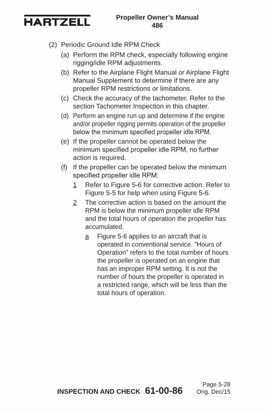
Propeller Owner’s Manual 486
INSPECTION AND CHECK 61-00-86Page 5-28
Orig. Dec/15
(2) Periodic Ground Idle RPM Check(a) Perform the RPM check, especially following engine
rigging/idle RPM adjustments.(b) Refer to the Airplane Flight Manual or Airplane Flight
Manual Supplement to determine if there are any propeller RPM restrictions or limitations.
(c) Check the accuracy of the tachometer. Refer to the section Tachometer Inspection in this chapter.
(d) Perform an engine run up and determine if the engine and/or propeller rigging permits operation of the propeller below the minimum specified propeller idle RPM.
(e) If the propeller cannot be operated below the minimum specified propeller idle RPM, no further action is required.
(f) If the propeller can be operated below the minimum specified propeller idle RPM:1 Refer to Figure 5-6 for corrective action. Refer to
Figure 5-5 for help when using Figure 5-6.2 The corrective action is based on the amount the
RPM is below the minimum propeller idle RPM and the total hours of operation the propeller has accumulated.a Figure 5-6 applies to an aircraft that is
operated in conventional service. "Hours of Operation" refers to the total number of hours the propeller is operated on an engine that has an improper RPM setting. It is not the number of hours the propeller is operated in a restricted range, which will be less than the total hours of operation.

Propeller Owner’s Manual 486
INSPECTION AND CHECK 61-00-86Page 5-29
Orig. Dec/15
(3) Corrective Action(a) The required corrective action is determined by both
the amount and duration of RPM deviation.1 A turboprop propeller with four or more blades
may have a variety of operating restrictions and these different restrictions may have different operating margins.
2 The greater the amount of the RPM deviation and the longer it is permitted to exist, the more severe the required corrective action.
3 The corrective action may vary from no action required to scrapping of the blades and the hub.
4 Refer to Figure 5-6 for the required corrective action.5 Contact Hartzell Propeller Inc. if further
clarification is required.6 If a propeller restriction other than those described
in Figure 5-6 has been violated, contact Hartzell Propeller Inc.a The chart in Figure 5-6 applies only to
operation below the minimum idle RPM.b The chart in Figure 5-6 does not apply to
other propeller restrictions that are above the minimum idle RPM.
7 If the corrective action requires a propeller overhaul, overhaul the propeller in accordance with the applicable propeller overhaul manuals.
8 If the corrective action requires that the blades and the hub be retired from service, retire these components from service in accordance with the Part Retirement Procedures chapter of Hartzell Propeller Inc. Standard Practices Manual 202A (61-01-02).
9 A propeller hub or blade that has been retired from service because of a violation of the operating restrictions as specified in this section must not be reused on another aircraft application.

Propeller Owner’s Manual 486
INSPECTION AND CHECK 61-00-86Page 5-30
Orig. Dec/15
10 If the corrective action requires the correction of the propeller RPM setting, refer to the applicable installation and rigging instructions for the adjustment of engine torque, engine idle speed, and propeller RPM setting.
11 Contact Hartzell Propeller Inc. Product Support Department to report the findings.Hartzell Propeller Inc. One Propeller Place Piqua, Ohio 45356-2634 USA Phone: 937.778.4379Fax: [email protected]
Propeller Owner’s Manual 486
INSPECTION AND CHECK 61-00-86Page 5-31
Orig. Dec/15
C. Lightning Strike
CAUTION 1: ALSO CONSULT AIRFRAME MANUFACTURER’S MANUALS. THERE MAY BE ADDITIONAL REQUIREMENTS, SUCH AS DE-ICE SYSTEM CHECKS, TO PERFORM IN THE EVENT OF PROPELLER LIGHTNING STRIKE.
CAUTION 2: A COMPOSITE BLADE SUSPECTED OF LIGHTNING STRIKE MUST BE INSPECTED AND MAY REQUIRE OVERHAUL.
NOTE: Lightning usually enters the propeller through the metal erosion shield or the stainless steel mesh (if applicable) of a blade. The charge typically enters at the tip of the blade and travels through the erosion shield toward the hub. The charge exits the erosion shield at the inboard end and enters the next conductive element in the path.
(1) General(a) In the event of a propeller lightning strike, an
inspection is required before further flight. It may be permissible to operate a propeller for an additional ten (10) hours of operation if the propeller is not severely damaged and meets the requirements in Procedures for Temporary Operation in this section.
(b) Regardless of the outcome of the initial inspection, the propeller must eventually be removed from the aircraft, disassembled, evaluated, and/or repaired by a certified propeller repair station with the appropriate rating.

Propeller Owner’s Manual 486
INSPECTION AND CHECK 61-00-86Page 5-32
Orig. Dec/15
(2) Procedure for Temporary OperationIf temporary additional operation is desired before propeller removal and disassembly:(a) Remove spinner dome and perform visual inspection
of propeller, spinner, and de-ice system for evidence of significant damage that would require repair before flight (such as broken de-ice wires or arcing damage to propeller hub).
CAUTION: IF THE PROPELLER EXPERIENCES A LIGHTNING STRIKE, THE COMPOSITE BLADES MUST BE WITHIN AIRWORTHY LIMITS FOR ANY ADDITIONAL FLIGHT.
(b) Perform a thorough visual inspection of the blades, looking for the indications of a lightning strike. If lightning strike damage is present, a brown burned mark and possible pitting, usually in proximity to the tip and at the most inboard end of the metal erosion shield, will be noticeable. Refer to Figure 5-7. If the blade has a de-ice boot installed, it may be debonded from the erosion shield due to the strike. In any case, the de-ice system may be damaged. Lightning strikes may also cause one or all of the following: debonding, lifting and buckling of the metal erosion shield, and delamination and splitting of the laminate.
Evidence of Lightning Strike Damage to Composite BladeFigure 5-7
W10
173
Brown Burn Mark on Erosion Shield From Lightning Strike
Propeller Owner’s Manual 486
INSPECTION AND CHECK 61-00-86Page 5-33
Orig. Dec/15
(c) Perform a coin-tap inspection of the composite blades that have indications of arcing. If the only evident damage is minor arcing and all other criteria do not exceed airworthy damage limits, stated in the Maintenance Practices chapter, then operation for ten (10) hours is acceptable before disassembly and inspection.
(d) Before further flight following a propeller lightning strike, Hartzell Propeller Inc. recommends replacement of the Metal Oxide Varistor (MOV) Module. Replacement should be done in accordance with AMM procedures. NOTE: The MOV Module is an airframe controlled
part installed to protect aircraft wiring from damage in the event of a propeller lightning strike. The MOV Module may be damaged during a lightning strike.
(e) Perform a functional check of the propeller de-ice system (if installed) in accordance with aircraft maintenance manual procedures.
(f) Regardless of the degree of damage, make an entry in the propeller logbook entry to document the lightning strike.
(g) The propeller must be removed from the aircraft, disassembled, evaluated, and/or repaired by a certified propeller repair station with the appropriate rating for flight beyond the temporary operation limits granted above.
Propeller Owner’s Manual 486
INSPECTION AND CHECK 61-00-86Page 5-34
Orig. Dec/15
D. Foreign Object Strike(1) General
(a) A foreign object strike can include a broad spectrum of damage, from a minor stone nick to severe ground impact damage. A conservative approach in evaluating the damage is required because there may be hidden damage that is not readily apparent during an on-wing, visual inspection.
(b) A foreign object strike is defined as:1 Any incident, whether or not the engine is
operating, that requires repair to the propeller other than minor dressing of the blades. Examples of foreign object strike include situations where an aircraft is stationary and the landing gear collapses causing one or more blades to be significantly damaged, or where a hangar door (or other object) strikes the propeller blade. These cases should be handled as foreign object strikes because of potentially severe side loading on the propeller hub, blades and retention bearings.
2 Any incident during engine operation in which the propeller impacts a solid object that causes a drop in revolutions per minute (RPM) and also requires structural repair of the propeller (incidents requiring only paint touch-up are not included). This is not restricted to propeller strikes against the ground.
3 A sudden RPM drop while impacting water, tall grass, or similar yielding medium, where propeller blade damage is not normally incurred.

Propeller Owner’s Manual 486
INSPECTION AND CHECK 61-00-86Page 5-35
Orig. Dec/15
(2) Procedure(a) In the event of a foreign object strike, an inspection
is required before further flight. If the inspection reveals one or more of the following indications, the propeller must be removed from the aircraft, disassembled, and overhauled in accordance with the applicable propeller and blade maintenance manuals:1 A loose blade in the hub.2 Any noticeable or suspected damage to the
pitch change mechanism. 3 A bent blade (out of track or angle).4 Any blade diameter reduction.5 A bent, cracked, or failed engine shaft.6 Vibration during operation that was not present
before the event.(b) For composite blades, perform a thorough visual
and coin tap test inspection of the exposed portion (de-ice boot removal not required) of each blade including the metal erosion shield (leading edge). 1 Refer to the Composite Blades section in the
Maintenance Practices chapter of this manual. 2 If the blade damage is beyond airworthy limits,
the blade must be repaired before further flight. 3 If the blade damage is beyond major repair
limits, the blade must either be returned to the factory for evaluation or removed from service.
(c) For engine mounted accessories (for example, governors, pumps, and propeller control units) manufactured by Hartzell Propeller Inc., if the foreign object strike resulted in a sudden stop of the engine, the unit must be disassembled and inspected in accordance with the applicable maintenance manual.
(d) Regardless of the degree of damage, make an entry in the propeller logbook to document the foreign object strike incident and any corrective action(s) taken.
Propeller Owner’s Manual 486
INSPECTION AND CHECK 61-00-86Page 5-36
Orig. Dec/15
E. Fire Damage or Heat Damage
WARNING 1: EXPOSING COMPOSITE BLADES TO HIGH TEMPERATURES MAY LEAD TO FAILURE THAT MAY CAUSE PERSONAL INJURY AND DEATH. COMPOSITE BLADES ARE SUBJECT TO DELAMINATIONS DUE TO HIGH TEMPERATURES.
WARNING 2: HUBS ARE MANUFACTURED FROM HEAT TREATED FORGINGS AND ARE SHOT PEENED. EXPOSURE TO HIGH TEMPERATURES CAN DESTROY THE FATIGUE RESISTANCE BENEFITS OBTAINED FROM THESE PROCESSES.
(1) On rare occasions propellers may be exposed to fire or heat damage, such as an engine or hangar fire. In the event of such an incident, an inspection by a certified propeller repair station with the appropriate rating is required before further flight.
6. Long Term StorageA. Parts shipped from Hartzell Propeller Inc. are not shipped
or packaged in a container that is designed for long term storage.
B. Long term storage procedures may be obtained by contacting a Hartzell Propeller Inc. distributor, or Hartzell Propeller Inc. via the Product Support number listed in the Introduction chapter of this manual. Storage information is also in Hartzell Propeller Inc. Manual 202A (61-01-02).
C. Information regarding the return of a propeller assembly to service after long term storage may be obtained by contacting a Hartzell Propeller Inc. distributor, or Hartzell Propeller Inc. via the Product Support number listed in the Introduction chapter of this manual. This information is also in Hartzell Propeller Inc. Manual 202A (61-01-02).
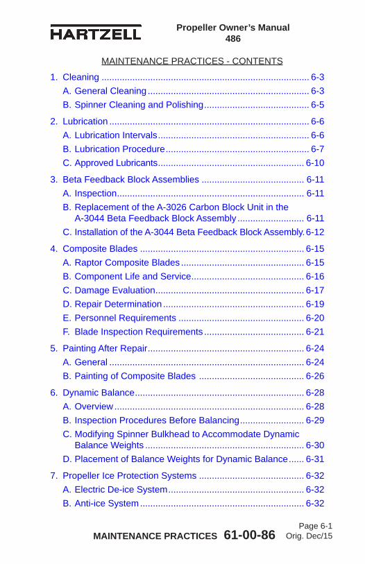
Propeller Owner’s Manual 486
MAINTENANCE PRACTICES 61-00-86Page 6-1
Orig. Dec/15
MAINTENANCE PRACTICES - CONTENTS
1. Cleaning ................................................................................. 6-3A. General Cleaning ............................................................... 6-3B. Spinner Cleaning and Polishing ......................................... 6-5
2. Lubrication .............................................................................. 6-6A. Lubrication Intervals ........................................................... 6-6B. Lubrication Procedure ........................................................ 6-7C. Approved Lubricants ......................................................... 6-10
3. Beta Feedback Block Assemblies ........................................ 6-11A. Inspection ......................................................................... 6-11B. Replacement of the A-3026 Carbon Block Unit in the A-3044 Beta Feedback Block Assembly .......................... 6-11C. Installation of the A-3044 Beta Feedback Block Assembly. 6-12
4. Composite Blades ................................................................ 6-15A. Raptor Composite Blades ................................................ 6-15B. Component Life and Service ............................................ 6-16C. Damage Evaluation .......................................................... 6-17D. Repair Determination ....................................................... 6-19E. Personnel Requirements ................................................. 6-20F. Blade Inspection Requirements ....................................... 6-21
5. Painting After Repair ............................................................. 6-24A. General ............................................................................ 6-24B. Painting of Composite Blades ......................................... 6-26
6. Dynamic Balance .................................................................. 6-28A. Overview .......................................................................... 6-28B. Inspection Procedures Before Balancing ......................... 6-29C. Modifying Spinner Bulkhead to Accommodate Dynamic Balance Weights .............................................................. 6-30D. Placement of Balance Weights for Dynamic Balance ...... 6-31
7. Propeller Ice Protection Systems ......................................... 6-32A. Electric De-ice System ..................................................... 6-32B. Anti-ice System ................................................................ 6-32
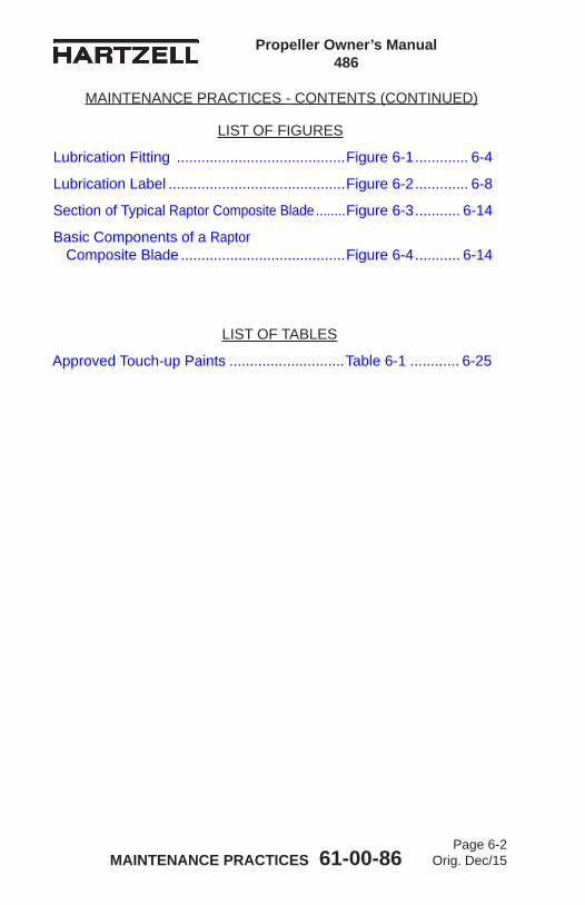
Propeller Owner’s Manual 486
MAINTENANCE PRACTICES 61-00-86Page 6-2
Orig. Dec/15
MAINTENANCE PRACTICES - CONTENTS (CONTINUED)
LIST OF TABLES
Approved Touch-up Paints ............................Table 6-1 ............ 6-25
LIST OF FIGURES
Lubrication Fitting .........................................Figure 6-1 ............. 6-4
Lubrication Label ...........................................Figure 6-2 ............. 6-8
Section of Typical Raptor Composite Blade ........Figure 6-3 ........... 6-14
Basic Components of a Raptor Composite Blade ........................................Figure 6-4 ........... 6-14

Propeller Owner’s Manual 486
MAINTENANCE PRACTICES 61-00-86Page 6-3
Orig. Dec/15
1. Cleaning
CAUTION 1: INSTRUCTIONS AND PROCEDURES IN THIS SECTION MAY INVOLVE PROPELLER CRITICAL PARTS. REFER TO THE INTRODUCTION CHAPTER OF THIS MANUAL FOR INFORMATION ABOUT PROPELLER CRITICAL PARTS. REFER TO THE ILLUSTRATED PARTS LIST CHAPTER OF THE APPLICABLE OVERHAUL MANUAL(S) FOR THE IDENTIFICATION OF SPECIFIC PROPELLER CRITICAL PARTS.
CAUTION 2: DO NOT USE PRESSURE WASHING EQUIPMENT TO CLEAN THE PROPELLER OR CONTROL COMPONENTS. PRESSURE WASHING CAN FORCE WATER AND/OR CLEANING SOLVENTS PAST SEALS, AND CAN LEAD TO INTERNAL CORROSION OF PROPELLER COMPONENTS.
A. General Cleaning
CAUTION 1: WHEN CLEANING THE PROPELLER, DO NOT ALLOW SOAP OR SOLVENT SOLUTIONS TO RUN OR SPLASH INTO THE HUB AREA.
CAUTION 2: DO NOT CLEAN THE PROPELLER WITH CAUSTIC OR ACIDIC SOAP SOLUTIONS. IRREPARABLE CORROSION OF PROPELLER COMPONENTS MAY OCCUR.
(1) Wash the propeller with a noncorrosive soap solution.

Propeller Owner’s Manual 486
MAINTENANCE PRACTICES 61-00-86Page 6-4
Orig. Dec/15
Lubrication Fitting Figure 6-1
Lubrication Fitting Removed From the Cylinder-side Hub Half
TI-0
0102
NOTE: A two-blade propeller is shown for illustration purposes only.
Cylinder
Inspection Mirror
Propeller Owner’s Manual 486
MAINTENANCE PRACTICES 61-00-86Page 6-5
Orig. Dec/15
WARNING: CLEANING AGENTS (ACETONE, #700 LACQUER THINNER, AND MEK), ARE FLAMMABLE AND TOXIC TO THE SKIN, EYES AND RESPIRATORY TRACT. SKIN AND EYE PROTECTION ARE REQUIRED. AVOID PROLONGED CONTACT. USE IN WELL VENTILATED AREA.
CAUTION: DO NOT USE ANY SOLVENT DURING CLEANING THAT COULD SOFTEN OR DESTROY THE BOND BETWEEN CHEMICALLY ATTACHED PARTS.
(2) To remove grease or oil from propeller surfaces, apply Stoddard Solvent or equivalent to a clean cloth and wipe the part clean.
(3) Thoroughly rinse in water and allow the part to dry.B. Spinner Cleaning and Polishing
(1) Clean the spinner using the General Cleaning procedures in this section.
(2) If an aluminum spinner is dome is installed, polish the dome (if required) with an automotive-type aluminum polish.

Propeller Owner’s Manual 486
MAINTENANCE PRACTICES 61-00-86Page 6-6
Orig. Dec/15
2. Lubrication
CAUTION: INSTRUCTIONS AND PROCEDURES IN THIS SECTION MAY INVOLVE PROPELLER CRITICAL PARTS. REFER TO THE INTRODUCTION CHAPTER OF THIS MANUAL FOR INFORMATION ABOUT PROPELLER CRITICAL PARTS. REFER TO THE ILLUSTRATED PARTS LIST CHAPTER OF THE APPLICABLE OVERHAUL MANUAL(S) FOR THE IDENTIFICATION OF SPECIFIC PROPELLER CRITICAL PARTS.
A. Lubrication Intervals(1) The propeller must be lubricated at intervals not to
exceed 400 hours or 12 calendar months, whichever occurs first, except as listed.(a) If annual operation is significantly less than
400 hours, calendar lubrication intervals should be reduced to six months.
(b) If the aircraft is operated or stored under adverse atmospheric conditions, e.g., high humidity, salt air, calendar lubrication intervals should be reduced to six months.
(2) Owners of high use aircraft may wish to extend their lubrication intervals. Lubrication interval may be gradually extended after evaluation of previous propeller overhauls with regard to bearing wear and internal corrosion.

Propeller Owner’s Manual 486
MAINTENANCE PRACTICES 61-00-86Page 6-7
Orig. Dec/15
(3) Hartzell Propeller Inc. recommends that new or newly overhauled propellers be lubricated after the first one or two hours of operation, because centrifugal loads will pack and redistribute grease, which may result in a propeller imbalance. Redistribution of grease may also result in voids in the blade bearing area where moisture can collect. (a) Purchasers of new aircraft should check the propeller
logbook to verify whether the propeller was lubricated by the manufacturer during flight testing. If it was not lubricated, the propeller should be serviced at the earliest convenience.
B. Lubrication ProcedureCAUTION: FOLLOW LUBRICATION PROCEDURES
CORRECTLY TO MAINTAIN ACCURATE BALANCE OF THE PROPELLER ASSEMBLY.
(1) Remove the propeller spinner.(2) Refer to Figure 6-1. Each blade socket has two lubrication
fittings. Remove the lubrication fitting caps from the lubrication fittings. Remove the lubrication fittings from either the engine side or the cylinder side of the hub assembly. NOTE: It is preferable to apply grease to the fitting located
nearest the leading edge of the blade on a tractor installation, or nearest the trailing edge on a pusher installation. Lubricating at this location reduces the possibility of grease bypassing the bearing area and entering the hub cavity.
(a) Some propellers use an internal blade seal that prevents grease from entering the hub cavity. Because this seal is very efficient, it is important to remove the opposite lubrication fitting. Pitch control difficulty could result if the propeller is not correctly lubricated.
(b) A 45 degree lubrication fitting (Hartzell Propeller Inc. P/N C-6349) may be installed on the engine-side or cylinder-side of the propeller in any location where a straight lubrication fitting (Hartzell Propeller Inc. P/N A-279) was originally installed. The 45 degree lubrication fitting simplifies lubrication.

Propeller Owner’s Manual 486
MAINTENANCE PRACTICES 61-00-86Page 6-8
Orig. Dec/15
(c) The lubrication fittings installed on the engine-side or cylinder-side must be either all straight (Hartzell Propeller Inc. P/N A-279) or all 45 degree (Hartzell Propeller Inc. P/N C-6349).
(3) Using a piece of safety wire to loosen any blockage or hardened grease at the threaded holes where the lubrication fitting was removed.
WARNING: WHEN MIXING AEROSHELL GREASES 5 AND 6, AEROSHELL GREASE 5 MUST BE INDICATED ON THE LABEL (HARTZELL PROPELLER INC. P/N A-3594) AND THE AIRCRAFT MUST BE PLACARDED TO INDICATE THAT FLIGHT IS PROHIBITED IF THE OUTSIDE AIR TEMPERATURE IS LESS THAN -40°F (-40°C).
CAUTION: USE HARTZELL PROPELLER INC. APPROVED GREASE ONLY. EXCEPT IN THE CASE OF AEROSHELL GREASES 5 AND 6, DO NOT MIX DIFFERENT SPECIFICATIONS AND/OR BRANDS OF GREASE.
(4) Aeroshell greases 5 and 6 both have a mineral oil base and have the same thickening agent; therefore, mixing of these two greases is acceptable in Hartzell Propeller Inc. propellers.
Lubrication Label Figure 6-2
A-3
594

Propeller Owner’s Manual 486
MAINTENANCE PRACTICES 61-00-86Page 6-9
Orig. Dec/15
(5) A label (Hartzell Propeller Inc. P/N A-3494) is normally applied to the propeller to indicate the type of grease previously used. Refer to Figure 6-2. (a) This grease type should be used during
re-lubrication unless the propeller has been disassembled and the old grease removed.
(b) It is NOT possible to purge old grease through lubrication fittings.
(c) To completely replace one grease with another, the propeller must be disassembled in accordance with the applicable overhaul manual.
CAUTION 1: OVER LUBRICATING AN ALUMINUM HUB PROPELLER MAY CAUSE THE GREASE TO ENTER THE HUB CAVITY, LEADING TO EXCESSIVE VIBRATION AND/OR SLUGGISH OPERATION. THE PROPELLER MUST THEN BE DISASSEMBLED TO REMOVE THIS GREASE.
CAUTION 2: IF A PNEUMATIC GREASE GUN IS USED, EXTRA CARE MUST BE TAKEN TO AVOID EXCESSIVE PRESSURE BUILDUP.
CAUTION 3: GREASE MUST BE APPLIED TO ALL BLADES OF A PROPELLER ASSEMBLY AT THE TIME OF LUBRICATION.
(6) Pump 1 fl. oz. (30 ml) grease into each engine-side lubrication fitting, or until grease emerges from the hole where the lubrication fitting was removed - whichever occurs first. NOTE: 1 fl. oz. (30 ml) is approximately 6 pumps with
a hand-operated grease gun.(7) Reinstall the removed lubrication fittings. Tighten until
snug. (a) Make sure that the ball of each lubrication fitting is
properly seated.(8) Reinstall a lubrication fitting cap on each lubrication
fitting.

Propeller Owner’s Manual 486
MAINTENANCE PRACTICES 61-00-86Page 6-10
Orig. Dec/15
C. Approved Lubricants(1) The following lubricants are approved for use in Hartzell
Propeller Inc. aluminum hub propellers:Aeroshell 6 - Recommended "all purpose" grease. Used
in most new production propellers since 1989. Higher leakage/oil separation than Aeroshell 5 at higher temperatures.
Aeroshell 5 - Good high temperature qualities, very little oil separation or leakage. Cannot be used in temperatures colder than -40°F (-40°C). Aircraft serviced with this grease must be placarded to indicate that flight is prohibited if the outside air temperature is less than -40°F (-40°C).
Aeroshell 7 - Good low temperature grease, but high leakage/oil separation at higher temperatures. This grease has been associated with sporadic problems involving seal swelling.
Aeroshell 22 - Qualities similar to Aeroshell 7. Royco 22CF - Not widely used. Qualities similar to
Aeroshell 22.NOTE: A label (Refer to Figure 6-2) indicating the type of
grease used for previous lubrication is installed on the propeller cylinder. If the propeller must be lubricated with another type of grease, the propeller must be disassembled and cleaned of old grease before relubricating.

Propeller Owner’s Manual 486
MAINTENANCE PRACTICES 61-00-86Page 6-11
Orig. Dec/15
3. Beta Feedback Block AssembliesA. Inspection
The clearance between the yoke pin and the corresponding linkage (beta lever bushing) can become too close because of a buildup of plating and foreign particles between the two pieces. This can cause a binding action, resulting in excessive wear to the carbon block unit, beta ring, and beta linkage.
CAUTION: INSTRUCTIONS AND PROCEDURES IN THIS SECTION MAY INVOLVE PROPELLER CRITICAL PARTS. REFER TO THE INTRODUCTION CHAPTER OF THIS MANUAL FOR INFORMATION ABOUT PROPELLER CRITICAL PARTS. REFER TO THE ILLUSTRATED PARTS LIST CHAPTER OF THE APPLICABLE OVERHAUL MANUAL(S) FOR THE IDENTIFICATION OF SPECIFIC PROPELLER CRITICAL PARTS.
(1) Inspect the beta lever and beta feedback block assembly interface for free movement. If there is binding, do the following:(a) Disconnect the beta linkage and remove the beta
feedback block assemblies from the beta ring.(b) Using fine emery cloth, polish the yoke pin to provide
adequate clearance and eliminate binding.(c) Reinstall the beta feedback block assembly into the
beta ring.(d) Install, adjust and safety the beta linkage in
accordance with the airframe manufacturer's instructions.
B. Replacement of the A-3026 Carbon Block Unit in the A-3044 Beta Feedback Block AssemblyReplace an A-3026 carbon block unit if the side clearance between the beta ring and carbon block unit is greater than 0.010 inch (0.25 mm).(1) Remove the cotter pin from the end of the clevis pin.(2) Slide the pin from the assembly and remove and discard
the carbon block unit.

Propeller Owner’s Manual 486
MAINTENANCE PRACTICES 61-00-86Page 6-12
Orig. Dec/15
(3) Inspect the yoke for wear or cracks. Replace the yoke if necessary.
(4) Install a new carbon block unit and slide a new clevis pin into place.
(5) Secure the clevis pin with a T-head cotter pin. Refer to Figure 3-7.
(6) Refit the beta feedback block assembly. Refer to Figure 3-6.(a) Establish the required clearance by sanding the
sides of the carbon block as needed.C. Installation of the A-3044 Beta Feedback Block Assembly
(1) Refer to the Installation and Removal chapter of this manual for installation instructions.

Propeller Owner’s Manual 486
MAINTENANCE PRACTICES 61-00-86Page 6-13
Orig. Dec/15
(This page is intentionally blank.)

Propeller Owner’s Manual 486
MAINTENANCE PRACTICES 61-00-86Page 6-14
Orig. Dec/15
Section of Typical Raptor Composite Blade Figure 6-3
Trailing Edge Foam Core
Blade Shell
Main Spar Foam Core
Main Spar
TI-0
0057
Basic Components of a Raptor Composite Blade Figure 6-4
ErosionShield
Shank of Metal Blade Plug See NOTE
Foam Core
CompositeMaterial
Trailing Edge Foam
TPI-1
35-1
04
NOTE: A Raptor blade for a turbine engine application uses a bolt on pitch change knob.
Propeller Owner’s Manual 486
MAINTENANCE PRACTICES 61-00-86Page 6-15
Orig. Dec/15
4. Composite BladesA. Raptor Composite Blades
(1) The Raptor blade is a monocoque construction consisting of composite material over a foam core.(a) For information about blade types, refer to Table 2-2,
"Blade Type and Blade Model Designations" in the Description and Operation chapter of this manual.
(2) The composite material is round at the inboard station sections, transitioning to an airfoil shape outboard on the blade. A typical airfoil section is shown in Figure 6-3. (a) The bulk of the composite material is truncated
toward the trailing edge with foam material forming the remainder of the trailing edge.
(b) The blades are of carbon construction.(3) An erosion shield of electroformed nickel is incorporated
in the fabrication to protect the leading edge of the blade from impact and erosion damage.
(4) The shank is constructed of stainless steel.(a) The outer shank uses a bolt on knob. Refer to
Figure 6-4.(5) The composite blade is balanced in the horizontal plane
during production by the addition of lead wool to a centrally located balance tube in the metal blade shank, which may protrude into the foam core of the blade.
(6) A finish covering of polyurethane paint protects the entire blade from erosion and ultraviolet damage.
(7) Aircraft that require ice protection use an external boot.
Propeller Owner’s Manual 486
MAINTENANCE PRACTICES 61-00-86Page 6-16
Orig. Dec/15
B. Component Life and Service(1) Overhaul or Major Periodic Inspection (MPI)
(a) Overhaul, or MPI, is the periodic disassembly, inspection, repair, refinish, and reassembly of the composite blade assembly.NOTE: The term “overhaul” is used throughout
the text of this manual.(b) At such specified periods, the propeller hub
assembly and the blade assemblies are completely disassembled and inspected for cracks, wear, corrosion, and other unusual or abnormal conditions. As specified, some blades are refinished, and other blades are replaced. The blades can then be reassembled and balanced.
(c) Overhaul procedures must be performed in accordance with the latest revision of Hartzell Propeller Inc. Composite Blade Maintenance Manual 135F (61-13-35) and other applicable publications.
(d) Overhaul must be performed only by a propeller repair station that is certified by Hartzell Propeller Inc. for composite blade overhaul.
(2) Blade LifeBlade life is expressed in terms of total hours of service (TT, or Total Time), time between overhauls (TBO) and in terms of service since overhaul (TSO, or Time Since Overhaul). All references are necessary in defining the life of the propeller.
Propeller Owner’s Manual 486
MAINTENANCE PRACTICES 61-00-86Page 6-17
Orig. Dec/15
C. Damage EvaluationNOTE: Specific Hartzell Propeller Inc. manuals and
service documents are available on the Hartzell Propeller Inc. website at www.hartzellprop.com. Refer to the Required Publications section in the Introduction chapter of this manual for the identification of these publications.
(1) Airworthy DamageCAUTION: ALTHOUGH A BLADE MAY CONTINUE
IN SERVICE WITH AIRWORTHY DAMAGE, THIS TYPE OF DAMAGE SHOULD BE REPAIRED AT THE EARLIEST PRACTICAL TIME.
(a) Airworthy damage is a specific condition to a blade that does not affect the safety or flight characteristics of the propeller blade and conforms to its type design by meeting the condition inspection criteria limitations found in Hartzell Propeller Inc. Composite Propeller Blade Field Maintenance and Minor Repair Manual 170 (61-13-70).1 The maximum limits of airworthy damage are
specified in Hartzell Propeller Inc. Composite Propeller Blade Field Maintenance and Minor Repair Manual 170 (61-13-70).
2 Hartzell Propeller Inc. Composite Propeller Blade Field Maintenance and Minor Repair Manual 170 (61-13-70) provides inspection criteria and direction to evaluate damage to determine continued airworthiness.
3 For ice protection system inspections, refer to the Anti-ice and De-ice Systems chapter of this manual.
(b) Although a blade may continue in service with airworthy damage, this type of damage should be repaired at the earliest practical time to prevent the damage from progressing to a condition that could require more extensive repair to the blade.

Propeller Owner’s Manual 486
MAINTENANCE PRACTICES 61-00-86Page 6-18
Orig. Dec/15
(2) Unairworthy DamageCAUTION: IN MOST CASES, UNAIRWORTHY
DAMAGE MUST BE REPAIRED BEFORE THE NEXT FLIGHT.
(a) Unairworthy damage is damage that is greater than the airworthy damage limits as specified in Hartzell Propeller Inc. Composite Blade Field Maintenance and Minor Repair Manual 170 (61-13-70). 1 Unairworthy damage can affect the safety or
flight characteristics of the propeller blade and does not conform to its type design.
2 This condition deems the blade unairworthy, requiring appropriate corrective action to repair or remove it from service, as applicable.
Propeller Owner’s Manual 486
MAINTENANCE PRACTICES 61-00-86Page 6-19
Orig. Dec/15
D. Repair DeterminationNOTE: Specific Hartzell Propeller Inc. manuals and
service documents are available on the Hartzell Propeller Inc. website at www.hartzellprop.com. Refer to the Required Publications section in the Introduction chapter of this manual for the identification of these publications.
(1) Minor Repair(a) Minor repair is correction of damage that may
be safely performed in the field by elementary operations.
(b) For complete description of minor repair and allowable procedures, refer to Hartzell Propeller Inc. Composite Blade Field Maintenance and Minor Repair Manual 170 (61-13-70).
(2) Major Repair(a) Major repair is correction of damage that cannot be
performed by elementary operations. (b) Major repair must be accepted by a certified aircraft
mechanic with an appropriate rating, preferably one that holds a Factory Training Certificate from Hartzell Propeller Inc.
(c) All major repairs must be performed by a propeller repair station that is certified by Hartzell Propeller Inc. and is an appropriately rated propeller repair station certified by the Federal Aviation Administration (FAA) or international equivalent.

Propeller Owner’s Manual 486
MAINTENANCE PRACTICES 61-00-86Page 6-20
Orig. Dec/15
E. Personnel RequirementsNOTE: Specific Hartzell Propeller Inc. manuals and
service documents are available on the Hartzell Propeller Inc. website at www.hartzellprop.com. Refer to the Required Publications section in the Introduction chapter of this manual for the identification of these publications.
(1) Anyone performing or accepting responsibility for an inspection, repair and/or overhaul of a Hartzell Propeller Inc. product must comply with the applicable regulatory requirements established by the appropriate Aviation Authority.
(2) Any person signing for or performing inspections and/or repairs to Hartzell Propeller Inc. composite parts should be familiar with the objectives and procedures associated with the inspection and/or repair of composite parts.
(3) For personnel requirements for repair of Hartzell Propeller Inc. composite blades, refer to Hartzell Propeller Inc. Composite Propeller Blade Field Maintenance and Minor Repair Manual 170 (61-13-70).

Propeller Owner’s Manual 486
MAINTENANCE PRACTICES 61-00-86Page 6-21
Orig. Dec/15
F. Blade Inspection Requirements
CAUTION: MAINTAINING A GOOD LOGBOOK RECORD IS PARTICULARLY IMPORTANT FOR COMPOSITE PROPELLER BLADES. DAMAGE AND/OR REPAIRS MAY SUFFER FURTHER DEGRADATION AFTER CONTINUED USE. SUCH DEGRADATION MAY BE EASILY OVERLOOKED. IT IS IMPORTANT FOR INSPECTORS TO HAVE ACCESS TO ACCURATE HISTORICAL DATA WHEN PERFORMING SUBSEQUENT INSPECTIONS.
NOTE: Specific Hartzell Propeller Inc. manuals and service documents are available on the Hartzell Propeller Inc. website at www.hartzellprop.com. Refer to the Required Publications section in the Introduction chapter of this manual for the identification of these publications.
(1) Required Record-Keeping(a) Composite blade damage and a description of the
repair must be recorded in the composite blade logbook.
(2) Preflight Inspection(a) Follow propeller preflight inspection procedures
as specified in the aircraft maintenance manual, or an air carrier’s operational specifications, or this manual. In addition, perform the following inspections:1 Visually inspect each entire blade for nicks,
gouges, loose material, erosion, cracks, and debonds.
2 Visually inspect each blade for lightning strike. Refer to “Lightning Strike Damage” in the Inspection and Check of this manual for a description of damage.
Propeller Owner’s Manual 486
MAINTENANCE PRACTICES 61-00-86Page 6-22
Orig. Dec/15
(b) Defects or damage discovered during preflight inspection must be evaluated in accordance with Hartzell Propeller Inc. Composite Propeller Blade Field Maintenance and Minor Repair Manual 170 (61-13-70).
(3) Maintenance Inspections(a) Inspection procedures must be performed in
accordance with this manual. 1 Perform a thorough visual inspection.2 Perform a coin-tap test to the exposed section
of the blade at intervals as required. For the required intervals, refer to the Periodic Inspections section of the Inspection and Check chapter of this manual.a Coin-tapping will indicate a delamination or
debond by an apparent audible change.b For the coin tap procedure for composite
blades, refer to Hartzell Propeller Inc. Composite Propeller Blade Field Maintenance and Minor Repair Manual 170 (61-13-70).
3 Review the blade logbook records and carefully inspect areas of airworthy damage and previously repaired areas for growth. If damage is growing, estimate if the damaged area will be greater than the permitted airworthy damage limits before the next overhaul. If this is the case, make arrangements to repair the damage at the earliest practical time to prevent further damage to the blade.

Propeller Owner’s Manual 486
MAINTENANCE PRACTICES 61-00-86Page 6-23
Orig. Dec/15
4 Defects or damage discovered during scheduled inspections must be evaluated in accordance with Hartzell Propeller Inc. Composite Propeller Blade Field Maintenance and Minor Repair Manual 170 (61-13-70) to determine if repairs are required before further flight. a Although repair of “airworthy damage” is not
essential before further flight, such damage should always be repaired as soon as possible to avoid further degradation.
b Unairworthy damage must be repaired before further flight.
(b) Make a record of the details of all damage and/or repairs in the composite blade logbook.
Propeller Owner’s Manual 486
MAINTENANCE PRACTICES 61-00-86Page 6-24
Orig. Dec/15
5. Painting After Repair
CAUTION: INSTRUCTIONS AND PROCEDURES IN THIS SECTION MAY INVOLVE PROPELLER CRITICAL PARTS. REFER TO THE INTRODUCTION CHAPTER OF THIS MANUAL FOR INFORMATION ABOUT PROPELLER CRITICAL PARTS. REFER TO THE ILLUSTRATED PARTS LIST CHAPTER OF THE APPLICABLE OVERHAUL MANUAL(S) FOR THE IDENTIFICATION OF SPECIFIC PROPELLER CRITICAL PARTS.
A. General(1) Propeller blades are painted with a durable specialized
coating that is resistant to abrasion. If this coating becomes eroded over an area of more than 10 square inches (6451.6 square mm), it is necessary to repaint the entire blade to provide proper environmental and erosion protection. Painting should be performed by a certified propeller repair station with the appropriate rating in accordance with Hartzell Propeller Inc. Standard Practices Manual 202A (61-01-02).
(2) For paint erosion over an area of less than 10 square inches (6451.6 square mm) it is permissible to perform a blade touch-up with aerosol paint in accordance with the procedures in Painting of Composite Blades that follow.
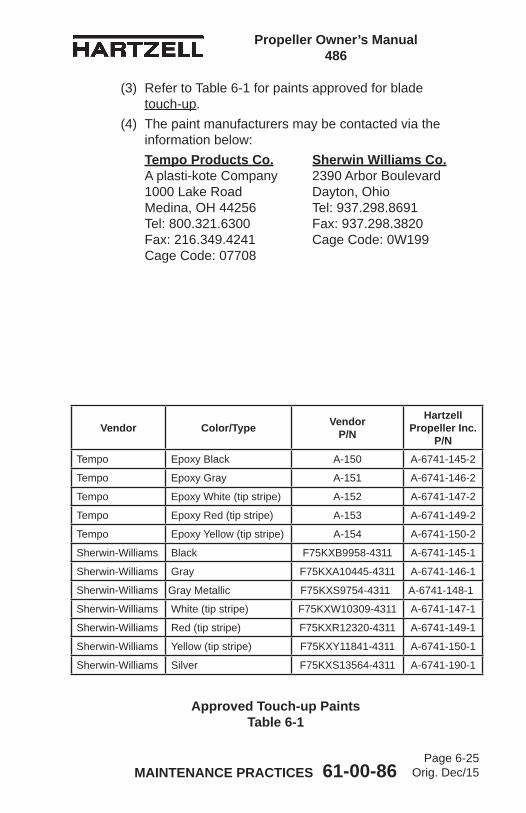
Propeller Owner’s Manual 486
MAINTENANCE PRACTICES 61-00-86Page 6-25
Orig. Dec/15
Approved Touch-up Paints Table 6-1
Vendor Color/Type Vendor P/N
Hartzell Propeller Inc.
P/NTempo Epoxy Black A-150 A-6741-145-2
Tempo Epoxy Gray A-151 A-6741-146-2
Tempo Epoxy White (tip stripe) A-152 A-6741-147-2
Tempo Epoxy Red (tip stripe) A-153 A-6741-149-2
Tempo Epoxy Yellow (tip stripe) A-154 A-6741-150-2
Sherwin-Williams Black F75KXB9958-4311 A-6741-145-1
Sherwin-Williams Gray F75KXA10445-4311 A-6741-146-1
Sherwin-Williams Gray Metallic F75KXS9754-4311 A-6741-148-1
Sherwin-Williams White (tip stripe) F75KXW10309-4311 A-6741-147-1
Sherwin-Williams Red (tip stripe) F75KXR12320-4311 A-6741-149-1
Sherwin-Williams Yellow (tip stripe) F75KXY11841-4311 A-6741-150-1
Sherwin-Williams Silver F75KXS13564-4311 A-6741-190-1
(3) Refer to Table 6-1 for paints approved for blade touch-up.
(4) The paint manufacturers may be contacted via the information below:
Tempo Products Co. Sherwin Williams Co. A plasti-kote Company 2390 Arbor Boulevard 1000 Lake Road Dayton, Ohio Medina, OH 44256 Tel: 937.298.8691 Tel: 800.321.6300 Fax: 937.298.3820 Fax: 216.349.4241 Cage Code: 0W199 Cage Code: 07708
Propeller Owner’s Manual 486
MAINTENANCE PRACTICES 61-00-86Page 6-26
Orig. Dec/15
B. Painting of Composite Blades
WARNING: CLEANING AGENTS (ACETONE, #700 LACQUER THINNER, AND MEK), ARE FLAMMABLE AND TOXIC TO THE SKIN, EYES AND RESPIRATORY TRACT. SKIN AND EYE PROTECTION ARE REQUIRED. AVOID PROLONGED CONTACT. USE IN WELL VENTILATED AREA.
CAUTION: ANY REFINISHING PROCEDURE CAN ALTER PROPELLER BALANCE. PROPELLERS THAT ARE OUT OF BALANCE MAY EXPERIENCE EXCESSIVE VIBRATIONS WHILE IN OPERATION.
(1) Using acetone, #700 lacquer thinner, or MEK, wipe the surface of the blade to remove any contaminants.
CAUTION: EXCESSIVE SANDING WILL CAUSE "FUZZING" OF THE KEVLAR® MATERIAL, RESULTING IN A ROUGH FINISH.
(2) Using 120 to 180 grit sandpaper, sand to feather the existing coatings away from the eroded or repaired area.(a) Erosion damage is typically very similar on all
blades in a propeller assembly. If one blade has more extensive damage, e.g., in the tip area, sand all the blades in the tip area to replicate the repair of the most severely damaged blade tip. This practice is essential in maintaining balance after refinishing.
(3) Using lacquer thinner #700 or MEK, wipe the surface of the blade, and permit the solvent to evaporate.
(4) Apply masking material for the erosion shield, de-ice boot, and tip stripes, as needed.

Propeller Owner’s Manual 486
MAINTENANCE PRACTICES 61-00-86Page 6-27
Orig. Dec/15
WARNING: FINISH COATINGS ARE FLAMMABLE AND TOXIC TO THE SKIN, EYES AND RESPIRATORY TRACT. SKIN AND EYE PROTECTION ARE REQUIRED. AVOID PROLONGED CONTACT. USE IN WELL VENTILATED AREA.
CAUTION: APPLY FINISH COATING ONLY TO THE DEGREE REQUIRED TO UNIFORMLY COVER THE REPAIR/EROSION. AVOID EXCESSIVE PAINT BUILDUP ALONG THE TRAILING EDGE TO AVOID CHANGING THE BLADE PROFILE AND/OR P-STATIC CHARACTERISTICS.
(5) Apply sufficient finish coating to achieve 2 to 4 mils thickness when dry. (a) Re-coat before 30 minutes or after 48 hours. (b) If the paint is permitted to dry longer than four (4)
hours, it must be lightly sanded before another coat is applied.
(6) Remove the masking from tip stripes and re-apply masking material for the tip stripe refinishing if required.
(7) Apply sufficient tip stripe coating to achieve 2 to 4 mils thickness when dry. (a) Re-coat before 30 minutes, or after 48 hours. (b) If the paint is permitted to dry longer than four (4)
hours, it must be lightly sanded before another coat is applied.
(8) Remove the masking immediately from the tip stripes and de-ice boot, if required.
(9) Optionally, perform dynamic balancing in accordance with the procedures and limitations specified in the Dynamic Balance section of this chapter.

Propeller Owner’s Manual 486
MAINTENANCE PRACTICES 61-00-86Page 6-28
Orig. Dec/15
6. Dynamic Balance
CAUTION: INSTRUCTIONS AND PROCEDURES IN THIS SECTION MAY INVOLVE PROPELLER CRITICAL PARTS. REFER TO THE INTRODUCTION CHAPTER OF THIS MANUAL FOR INFORMATION ABOUT PROPELLER CRITICAL PARTS. REFER TO THE ILLUSTRATED PARTS LIST CHAPTER OF THE APPLICABLE OVERHAUL MANUAL(S) FOR THE IDENTIFICATION OF SPECIFIC PROPELLER CRITICAL PARTS.
A. OverviewNOTE: Dynamic balance is recommended to reduce
vibrations that may be caused by a rotating system (propeller and engine) imbalance. Dynamic balancing can help prolong the life of the propeller, engine, airframe, and avionics.
(1) Dynamic balance is accomplished by using an accurate means of measuring the amount and location of the dynamic imbalance.
(2) The number of balance weights installed must not exceed the limits specified in this chapter.
(3) Follow the dynamic balance equipment manufacturer’s instructions for dynamic balance, in addition to the specifications of this section.NOTE: Some engine manufacturers' instructions also
contain information about dynamic balance limits.
Propeller Owner’s Manual 486
MAINTENANCE PRACTICES 61-00-86Page 6-29
Orig. Dec/15
B. Inspection Procedures Before Balancing(1) Visually inspect the propeller assembly before dynamic
balancing.NOTE: The first run-up of a new or overhauled
propeller assembly may leave a small amount of grease on the blades and inner surface of the spinner dome.
(a) Use Stoddard solvent (or equivalent) to completely remove any grease on the blades or inner surface of the spinner dome.
(b) Visually examine each propeller blade assembly for evidence of grease leakage.
(c) Visually examine the inner surface of the spinner dome for evidence of grease leakage.
(2) If there is no evidence of grease leakage, lubricate the propeller in accordance with the Maintenance Practices chapter in this manual. If grease leakage is evident, determine the location of the leak and correct before re-lubricating the propeller and dynamic balancing.
(3) Before dynamic balancing, record the number and location of all balance weights.
(4) Static balance is accomplished at an appropriately rated propeller repair station that is certified by the Federal Aviation Administration (FAA) or international equivalent when an overhaul or major repair is performed. NOTE: If static balancing is not accomplished before
dynamic balancing, the propeller may be so severely unbalanced that it may not be possible to achieve dynamic balance.

Propeller Owner’s Manual 486
MAINTENANCE PRACTICES 61-00-86Page 6-30
Orig. Dec/15
C. Modifying Spinner Bulkhead to Accommodate Dynamic Balance Weights
CAUTION 1: DO NOT MODIFY A COMPOSITE SPINNER BULKHEAD TO ACCOMMODATE DYNAMIC BALANCE WEIGHTS.
CAUTION 2: ALL HOLE/BALANCE WEIGHT LOCATIONS MUST TAKE INTO CONSIDERATION AND MUST AVOID, ANY POSSIBILITY OF INTERFERING WITH THE ADJACENT AIRFRAME, ICE PROTECTION SYSTEM, AND ENGINE COMPONENTS.
(1) It is recommended that the placement of balance weights be in a radial location on the aluminum spinner bulkheads that have not been previously drilled.
(2) The radial location should be outboard of the de-ice slip ring or bulkhead doubler and inboard of the bend where the bulkhead creates the flange surface to attach the spinner dome.
(3) Equally spaced locations for weight attachment are recommended.
(4) Installing nut plates (10-32 thread) of the type used to attach the spinner dome will permit convenient balance weight attachment on the engine side of the bulkhead.
(5) Alternatively, drilling holes for use with the AN3-( ) type bolts with self-locking nuts is permitted.
(6) Chadwick-Helmuth Manual AW-9511-2, “The Smooth Propeller”, specifies several generic bulkhead rework procedures. These are permitted if they comply with the conditions specified herein.

Propeller Owner’s Manual 486
MAINTENANCE PRACTICES 61-00-86Page 6-31
Orig. Dec/15
D. Placement of Balance Weights for Dynamic Balance(1) The preferred method of attachment of dynamic balance
weights is to add the weights to the spinner bulkhead.NOTE: Many spinner bulkheads have factory installed
self-locking nut plates provided for this purpose.
(2) If the location of static balance weights has not been altered, subsequent removal of the dynamic balance weights will return the propeller to its original static balance condition.
(3) Use only stainless or plated steel washers as dynamic balance weights on the spinner bulkhead.
(4) A maximum of six AN970 style washers weighing up to approximately 1.0 oz (28.0 g) maybe installed at any one location.NOTE: The dimensions of an AN970 washer are:
ID 0.203 inch (5.16 mm), OD 0.875 inch (22.23 mm), and thickness 0.063 inch (1.59 mm).
(5) Install weights using aircraft quality #10-32 or AN-3( ) type screws or bolts.
(6) Torque the screws or bolts in accordance with Torque Table 3-2.
(7) Balance weight screws attached to the spinner bulkhead must protrude through the self-locking nuts or nut plates a minimum of one thread and a maximum of four threads.(a) Make sure that the screw or bolt grip length is short
enough to prevent interference with the nut or nut plate when the correct torque is applied.
(b) It may be necessary to alter the number and/or location of static balance weights in order to achieve dynamic balance.

Propeller Owner’s Manual 486
MAINTENANCE PRACTICES 61-00-86Page 6-32
Orig. Dec/15
(8) Unless otherwise specified by the engine or airframe manufacturer, Hartzell Propeller Inc. recommends that the propeller be dynamically balanced to a reading of 0.2 IPS, or less.
(9) Make a record in the propeller logbook of the number and location of dynamic balance weights and static balance weights, if they have been reconfigured.
7. Propeller Ice Protection SystemsA. Electric De-ice System
(1) Consult the Pilot Operating Handbook (including all supplements) regarding flight into conditions of known icing. The aircraft may not be certificated for flight in known icing conditions, even though propeller de-ice equipment is installed.
(2) Refer to the Anti-ice and De-ice Systems chapter of this manual for functional tests of the de-ice system.
B. Anti-ice System(1) Consult the Pilot Operating Handbook (including all
supplements) regarding flight into conditions of known icing. The aircraft may not be certificated for flight in known icing conditions, even though propeller anti-ice equipment is installed.
(2) Refer to the Anti-ice and De-ice Systems chapter of this manual for functional tests of the anti-ice system.
Propeller Owner’s Manual 486
ANTI-ICE AND DE-ICE SYSTEMS 61-00-86Page 7-1
Orig. Dec/15
ANTI-ICE AND DE-ICE SYSTEMS - CONTENTS
1. Introduction .............................................................................. 7-3A. Propeller De-ice System .................................................... 7-3B. Anti-ice System .................................................................. 7-3
2. System Description ................................................................. 7-4A. De-ice System .................................................................... 7-4B. Anti-ice System .................................................................. 7-5
3. De-ice System Functional Tests ............................................. 7-5
4. Anti-ice System Functional Tests ............................................ 7-5
5. De-ice and Anti-ice System Inspections ................................. 7-6A. De-ice System Inspections ................................................ 7-6B. Anti-ice System Inspections ............................................... 7-6
6. De-ice and Anti-ice System Troubleshooting .......................... 7-7A. De-ice System Troubleshooting ......................................... 7-7B. Anti-ice System Troubleshooting ....................................... 7-7

Propeller Owner’s Manual 486
ANTI-ICE AND DE-ICE SYSTEMS 61-00-86Page 7-2
Orig. Dec/15
(This page is intentionally blank.)
Propeller Owner’s Manual 486
ANTI-ICE AND DE-ICE SYSTEMS 61-00-86Page 7-3
Orig. Dec/15
1. IntroductionA. Propeller De-ice System
(1) A propeller de-ice system is a system that removes ice after it forms on the propeller blades. A de-ice system uses electrical heating elements to melt the ice layer next to the blades, allowing the ice to be thrown from the blade by centrifugal force. The de-ice system timer controls the application of current to the blades, alternately heating them and permitting them to cool.
(2) System components include a timer or cycling unit, electrical slip ring(s), brush block assembly, and blade mounted de-ice boots.
B. Anti-ice System(1) A propeller anti-ice system is a system that prevents
formation of ice on propeller surfaces. An anti-ice system dispenses a fluid that mixes with, and reduces the freezing point of, moisture on the propeller blades. The mixture may then flow off the blades before it forms ice.
(2) System components include a fluid tank, pump, slinger ring, and blade mounted fluid anti-icing boots.

Propeller Owner’s Manual 486
ANTI-ICE AND DE-ICE SYSTEMS 61-00-86Page 7-4
Orig. Dec/15
2. System DescriptionA. De-ice System
NOTE: Because of the many differences in various de-ice systems, the following description is general in nature. Consult the airframe manufacturer’s manual for a description of your specific de-ice system and controls.
The de-ice system is controlled by the pilot via a cockpit control switch. This switch applies power to the de-ice system, which will operate as long as the switch is in the ON position. Depending upon the system, another set of cockpit controls may be available. One of these controls is a mode selector, which allows the pilot to select two cycling speeds, for heavy or light icing conditions. Some systems on twin engine aircraft have a switch that provides a full de-ice mode, which allows the pilot to de-ice both propellers simultaneously. This switch may only be used for short periods and is used when ice builds up on the propeller before the system is turned on.(1) An ammeter, which indicates current drawn by the
system, is normally located near the de-ice system switches. This ammeter may indicate total system load, or a separate ammeter may be supplied for each propeller.
(2) A timer, which is turned off and on by the cockpit control, is used to sequence the de-ice system. This timer turns the de-ice system on and off in proper sequence, controlling the heating interval for each propeller blade and ensuring even de-icing.
(3) A brush block mounted on the engine immediately behind the propeller supplies electric current to the de-ice boot on each propeller blade via a slip ring. The slip ring is normally mounted on the spinner bulkhead.
(4) When the pilot places the de-ice system cockpit control switch in the ON position, the system timer begins to operate. As the timer sequences, power is delivered to a power relay. The power relay delivers high current through the brush block and slip ring to the de-ice boot.

Propeller Owner’s Manual 486
ANTI-ICE AND DE-ICE SYSTEMS 61-00-86Page 7-5
Orig. Dec/15
B. Anti-ice System(1) The anti-ice system is controlled by the pilot via a cockpit
mounted rheostat. This rheostat operates a pump that pumps anti-ice fluid from the tank at a controlled rate.
(2) The anti-ice fluid is delivered through a filter, a check valve, and then through tubing to a slinger ring located at the rear of the spinner bulkhead. The anti-ice fluid is dispensed into the rotating slinger ring, which holds the fluid in a curved channel by centrifugal force. The fluid then flows out of the slinger ring through feed tubes which are welded to the slinger ring, and then out onto the blade anti-icing boots.
(3) The blade anti-icing boots are ridged rubber sheets that are glued to the leading edge of the blades. The ridges in the anti-icing boots direct the fluid out onto the blades and permit for an even distribution of the anti-ice fluid across the blades.
3. De-ice System Functional TestsA. Functional tests of the de-ice system should be performed
in accordance with the following Hartzell Propeller Inc. Manuals, which are available on the Hartzell Propeller Inc. website at www.hartzellprop.com:(1) Hartzell Propeller Inc. Manual No. 181 (30-60-81) -
Propeller Ice Protection System Component Maintenance Manual
(2) Hartzell Propeller Inc. Manual No. 182 (61-12-82) - Propeller Electrical De-ice Boot Removal and Installation Manual
4. Anti-ice System Functional TestsA. Operational Checks of the anti-ice system should be
performed in accordance with the following Hartzell Manuals, which are available on the Hartzell Propeller website at www.hartzellprop.com:(1) Hartzell Propeller Inc. Manual 181 (30-60-81) - Propeller
Ice Protection System Component Maintenance Manual(2) Hartzell Propeller Inc. Manual 183 (61-12-83) - Propeller
Anti-icing Boot Removal and Installation Manual

Propeller Owner’s Manual 486
ANTI-ICE AND DE-ICE SYSTEMS 61-00-86Page 7-6
Orig. Dec/15
5. De-ice and Anti-ice System InspectionsThe inspections are made on a regular basis, either before flight, during the 100 hour inspection, or if a problem is noted. Possible corrections to problems discovered during inspections, additional inspections, and limits are detailed in the following Hartzell Propeller Inc. manuals, which are available on the Hartzell Propeller Inc. website at www.hartzellprop.com:A. De-ice System Inspections
(1) Perform inspections in accordance with the following Hartzell Propeller Inc. manuals, which are available on the Hartzell Propeller Inc. website at www.hartzellprop.com:(a) Hartzell Propeller Inc. Manual No. 181 (30-60-81) -
Propeller Ice Protection System Component Maintenance Manual
(b) Hartzell Propeller Inc. Manual No. 182 (61-12-82) - Propeller Electrical De-ice Boot Removal and Installation Manual
B. Anti-ice System Inspections(1) Perform inspections in accordance with the
following Hartzell Propeller Inc. manuals, which are available on the Hartzell Propeller Inc. website at www.hartzellprop.com:(a) Hartzell Propeller Inc. Manual 181 (30-60-81) -
Propeller Ice Protection System Component Maintenance Manual
(b) Hartzell Propeller Inc. Manual 183 (61-12-83) - Propeller Anti-icing Boot Removal and Installation Manual
Propeller Owner’s Manual 486
ANTI-ICE AND DE-ICE SYSTEMS 61-00-86Page 7-7
Orig. Dec/15
6. De-ice and Anti-ice System TroubleshootingA. De-ice System Troubleshooting
(1) Perform troubleshooting in accordance with the following Hartzell Propeller Inc. manuals, which are available on the Hartzell Propeller Inc. website at www.hartzellprop.com:(a) Hartzell Propeller Inc. Manual No. 181 (30-60-81) -
Propeller Ice Protection Component Maintenance Manual
(b) Hartzell Propeller Inc. Manual No. 182 (61-12-82) - Propeller Electrical De-ice Boot Removal and Installation Manual
B. Anti-ice System Troubleshooting(1) Perform troubleshooting in accordance with the
following Hartzell Propeller Inc. manuals, which are available on the Hartzell Propeller Inc. website at www.hartzellprop.com:(a) Hartzell Propeller Inc. Manual No. 181 (30-60-81) -
Propeller Ice Protection System Component Maintenance Manual
(b) Hartzell Propeller Inc. Manual No. 183 (61-12-83) - Propeller Anti-icing Boot Removal and Installation Manual

Propeller Owner’s Manual 486
ANTI-ICE AND DE-ICE SYSTEMS 61-00-86Page 7-8
Orig. Dec/15
(This page is intentionally blank.)

RECORDS 61-00-86Page 8-1
Orig. Dec/15
Propeller Owner’s Manual 486
RECORDS - CONTENTS
1. Introduction .............................................................................. 8-3
2. Record Keeping ....................................................................... 8-3A. Information to be Recorded ................................................ 8-3B. Blade Damage Repair Sheets ............................................ 8-3 78D01( ) .............................................................................. 8-4

RECORDS 61-00-86Page 8-2
Orig. Dec/15
Propeller Owner’s Manual 486
(This page is intentionally blank.)

RECORDS 61-00-86Page 8-3
Orig. Dec/15
Propeller Owner’s Manual 486
1. IntroductionFederal Aviation Regulations require that a record be kept of any repairs, adjustments, maintenance, or required inspections performed on a propeller or propeller system.This chapter provides a method for maintaining these records. It also provides a location for recording information that can aid the service technician in maintaining the propeller system.
2. Record KeepingA. Information to be Recorded
(1) Information that is required to be recorded is listed in Part 43 of the U.S. Federal Aviation Regulations.
(2) The log book may also be used to record:(a) Propeller position (on aircraft)(b) Propeller model(c) Propeller serial number(d) Blade design number(e) Blade serial numbers(f) Spinner assembly part number(g) Propeller pitch range(h) Aircraft information (aircraft type, model, serial
number and registration number)B. Blade Damage Repair Sheets
NOTE: The use of the Blade Damage Repair Sheets in this chapter is at the discretion of the user.

RECORDS 61-00-86Page 8-4
Orig. Dec/15
Propeller Owner’s Manual 486
Rec
ord
of 7
8D01
( ) C
ompo
site
Bla
de D
amag
e R
epai
r
Bla
de S
eria
l No.
___
____
___
Face
Cam
ber
Bla
de
Sta
tion
01.
135
812
1824
3036
3839
.013

RECORDS 61-00-86Page 8-5
Orig. Dec/15
Propeller Owner’s Manual 486
Rec
ord
of 7
8D01
( ) C
ompo
site
Bla
de D
amag
e R
epai
r
Bla
de S
eria
l No.
___
____
___
Face
Cam
ber
Bla
de
Sta
tion
01.
135
812
1824
3036
3839
.013

RECORDS 61-00-86Page 8-6
Orig. Dec/15
Propeller Owner’s Manual 486
Rec
ord
of 7
8D01
( ) C
ompo
site
Bla
de D
amag
e R
epai
r
Bla
de S
eria
l No.
___
____
___
Face
Cam
ber
Bla
de
Sta
tion
01.
135
812
1824
3036
3839
.013
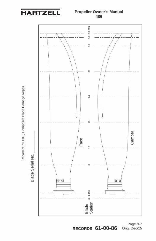
RECORDS 61-00-86Page 8-7
Orig. Dec/15
Propeller Owner’s Manual 486
Rec
ord
of 7
8D01
( ) C
ompo
site
Bla
de D
amag
e R
epai
r
Bla
de S
eria
l No.
___
____
___
Face
Cam
ber
Bla
de
Sta
tion
01.
135
812
1824
3036
3839
.013
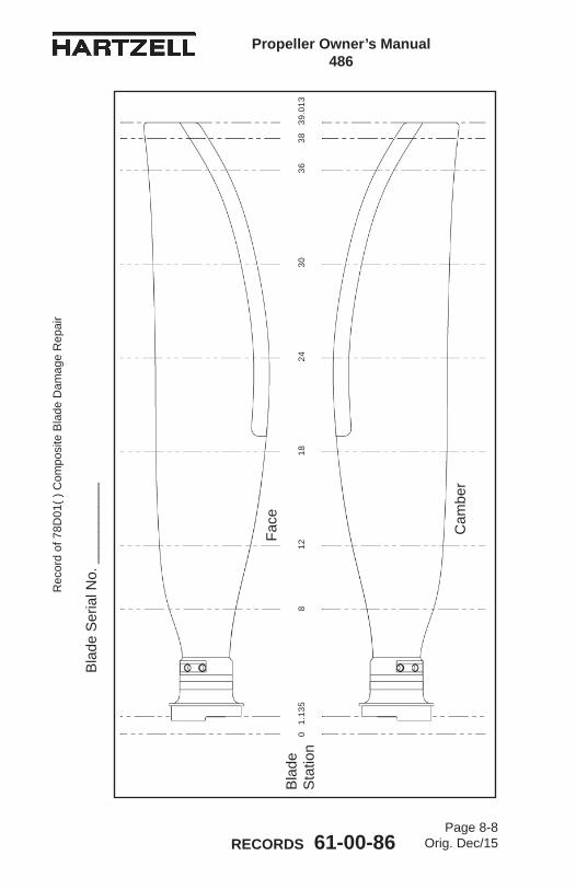
RECORDS 61-00-86Page 8-8
Orig. Dec/15
Propeller Owner’s Manual 486
Rec
ord
of 7
8D01
( ) C
ompo
site
Bla
de D
amag
e R
epai
r
Bla
de S
eria
l No.
___
____
___
Face
Cam
ber
Bla
de
Sta
tion
01.
135
812
1824
3036
3839
.013